

Page 1

R&S®SMA100B
RF Signal Generator
User Manual
(;ÜVR2)
1178383402
Version 09
Page 2

This document describes the R&S®SMA100B models, stock no. 1419.8888.02 and its options:
●
R&S®SMAB-B1H
●
R&S®SMAB-B28
●
R&S®SMAB-B29
●
R&S®SMAB-B32/-B34/-B35/-B36S/-B37/-B39
●
R&S®SMAB-B80/-B85
●
R&S®SMAB-B81/-B82
●
R&S®SMAB-B86
●
R&S®SMAB-B92/-B93
●
R&S®SMAB-B103/-B106/-B112/-B120/-B131/-B140(N)/-B150(N)/-B167(N)
●
R&S®SMAB-B709/-B710(N)/-B711(N)
●
R&S®SMAB-K22/-K23/-K24/-K27
●
R&S®SMAB-K25
●
R&S®SMAB-K28
●
R&S®SMAB-K31/-K33
●
R&S®SMAB-K33/-K36/-K38/-K40
●
R&S®SMAB-K40
●
R&S®SMAB-K703
●
R&S®SMAB-K704
●
R&S®SMAB-K720/-K721
●
R&S®SMAB-K722
●
R&S®SMAB-K723
●
R&S®SMAB-K724
●
R&S®SMAB-K725
●
R&S®SMAB-K726
This manual describes firmware version FW 5.00.122.xx and later of the R&S®SMA100B.
© 2022 Rohde & Schwarz GmbH & Co. KG
Muehldorfstr. 15, 81671 Muenchen, Germany
Phone: +49 89 41 29 - 0
Email: info@rohde-schwarz.com
Internet: www.rohde-schwarz.com
Subject to change – data without tolerance limits is not binding.
R&S® is a registered trademark of Rohde & Schwarz GmbH & Co. KG.
Trade names are trademarks of the owners.
1178.3834.02 | Version 09 | R&S®SMA100B
Throughout this manual, products from Rohde & Schwarz are indicated without the ® symbol , e.g. R&S®SMA100B is indicated as
R&S SMAB. Linux® is abbreviated as Linux.
Page 3

R&S®SMA100B
1 Safety and regulatory information......................................................19
1.1 Safety instructions......................................................................................................19
1.2 Labels on R&S SMA100B........................................................................................... 21
1.3 Warning messages in the documentation................................................................ 22
1.4 Korea certification class A......................................................................................... 22
2 Welcome............................................................................................... 23
2.1 Key features.................................................................................................................23
2.2 What's new...................................................................................................................23
2.3 Documentation overview............................................................................................23
2.3.1 Getting started manual..................................................................................................24
Contents
Contents
2.3.2 User manuals and help................................................................................................. 24
2.3.3 Service manual............................................................................................................. 24
2.3.4 Instrument security procedures.....................................................................................24
2.3.5 Printed safety instructions............................................................................................. 24
2.3.6 Data sheets and brochures........................................................................................... 24
2.3.7 Release notes and open source acknowledgment (OSA)............................................ 25
2.3.8 Application notes, application cards, white papers, etc.................................................25
3 Getting started......................................................................................26
3.1 Preparing for use........................................................................................................ 26
3.1.1 Lifting and carrying........................................................................................................26
3.1.2 Unpacking and checking............................................................................................... 26
3.1.3 Choosing the operating site.......................................................................................... 26
3.1.4 Setting up the R&S SMA100B...................................................................................... 27
3.1.4.1 Placing the R&S SMA100B on a bench top.................................................................. 27
3.1.4.2 Mounting the R&S SMA100B in a rack......................................................................... 28
3.1.5 Considerations for test setup........................................................................................ 29
3.1.6 Connecting to power..................................................................................................... 30
3.1.7 Connecting to LAN........................................................................................................ 30
3.1.8 Connecting USB devices.............................................................................................. 31
3.1.9 Connecting to RF.......................................................................................................... 32
3.1.10 Connecting to Ref In/Ref Out........................................................................................ 33
3User Manual 1178.3834.02 ─ 09
Page 4

R&S®SMA100B
3.1.11 Switching on or off.........................................................................................................34
3.2 Instrument tour............................................................................................................35
3.2.1 Front panel tour.............................................................................................................36
3.2.1.1 Touchscreen..................................................................................................................37
3.2.1.2 Utility keys..................................................................................................................... 38
3.2.1.3 On/Standby................................................................................................................... 38
3.2.1.4 Function keys................................................................................................................ 38
3.2.1.5 Keypad.......................................................................................................................... 38
3.2.1.6 Navigation controls........................................................................................................39
3.2.1.7 Display keys.................................................................................................................. 40
Contents
Rotary knob...................................................................................................................39
editing keys................................................................................................................... 39
Navigation keys.............................................................................................................40
3.2.1.8 SD card slot...................................................................................................................40
3.2.1.9 USB connector.............................................................................................................. 40
3.2.1.10 Sensor...........................................................................................................................41
3.2.1.11 RF 50 Ω.........................................................................................................................41
3.2.1.12 Pulse signal connectors................................................................................................ 42
3.2.1.13 LF modulation connectors.............................................................................................42
3.2.1.14 Clock synthesizer connectors....................................................................................... 42
3.2.2 Rear panel tour............................................................................................................. 43
3.2.2.1 Connectors....................................................................................................................44
3.3 Trying out the instrument...........................................................................................46
3.3.1 Generating an unmodulated carrier.............................................................................. 46
3.3.2 Generating an RF frequency sweep signal................................................................... 49
3.3.3 Saving and recalling settings........................................................................................ 51
3.4 Instrument control...................................................................................................... 53
3.4.1 Possible ways to operate the instrument...................................................................... 54
3.4.2 Means of manual interaction......................................................................................... 54
3.4.3 Understanding the display information..........................................................................55
3.4.3.1 Status bar......................................................................................................................56
3.4.3.2 Tile diagram...................................................................................................................56
3.4.3.3 Taskbar..........................................................................................................................56
4User Manual 1178.3834.02 ─ 09
Page 5

R&S®SMA100B
3.4.3.4 Additional display characteristics.................................................................................. 57
3.4.4 Accessing the functionality............................................................................................58
3.4.5 Entering data.................................................................................................................59
3.4.5.1 Entering numeric parameters........................................................................................60
3.4.5.2 Entering alphanumeric parameters............................................................................... 60
3.4.5.3 Undo and redo actions.................................................................................................. 60
3.4.6 Getting information and help......................................................................................... 61
3.4.7 Remote control..............................................................................................................62
3.4.8 Remote operation over VNC......................................................................................... 63
4 RF signal configuration.......................................................................64
4.1 Activating RF signal output....................................................................................... 65
4.2 How to set the frequency and level........................................................................... 65
Contents
4.3 Phase continuous frequency..................................................................................... 67
4.3.1 How to generate a phase continuous RF signal........................................................... 67
4.4 RF connector settings................................................................................................ 68
4.5 RF frequency settings................................................................................................ 71
4.6 RF level settings..........................................................................................................74
4.7 RF phase settings....................................................................................................... 78
5 Analog modulations.............................................................................81
5.1 Required options.........................................................................................................81
5.2 Modulation types and signal sources....................................................................... 81
5.3 Activating analog modulations..................................................................................84
5.4 Modulation settings.................................................................................................... 84
5.4.1 Pulse modulation settings............................................................................................. 84
5.4.2 FM, PhiM and AM modulation settings......................................................................... 86
5.4.3 Chirp modulation........................................................................................................... 93
5.4.3.1 Chirp modulation settings..............................................................................................94
Chirp modulation........................................................................................................... 95
Pulse external / trigger.................................................................................................. 97
5.4.4 Pulse generator.............................................................................................................98
5.4.4.1 Pulse generator > general settings............................................................................... 99
5.4.4.2 Pulse generator > pulse train settings.........................................................................104
5.4.4.3 Import/export list files.................................................................................................. 108
5User Manual 1178.3834.02 ─ 09
Page 6

R&S®SMA100B
5.4.5 Pulse graph..................................................................................................................111
5.4.6 Pulse external / trigger settings................................................................................... 112
5.4.7 FM, PhiM and AM modulation sources........................................................................113
5.4.7.1 Source > LF generator settings...................................................................................113
5.4.7.2 Source > external settings...........................................................................................117
5.4.7.3 Source > noise generator settings...............................................................................119
5.4.8 LF signal output settings............................................................................................. 120
5.4.9 Overview..................................................................................................................... 122
5.5 How to generate an amplitude modulated signal.................................................. 124
5.6 How to generate a pulse modulated signal............................................................ 124
5.7 How to generate a pulse train modulated signal................................................... 125
6 Avionic standards..............................................................................127
Contents
6.1 Required options.......................................................................................................127
6.2 About the Avionics options......................................................................................127
6.2.1 Required options......................................................................................................... 128
6.2.2 VHF omni directional radio range (VOR).................................................................... 128
6.2.3 Instrument landing system (ILS)................................................................................. 129
6.2.4 Automatic direction finder (ADF)................................................................................. 133
6.3 VOR configuration and settings.............................................................................. 133
6.3.1 General settings.......................................................................................................... 134
6.3.2 Signal settings.............................................................................................................137
6.3.3 Position settings.......................................................................................................... 139
6.3.4 COM/ID settings..........................................................................................................140
6.4 ILS configuration and settings................................................................................ 142
6.4.1 General settings.......................................................................................................... 142
6.4.2 ILS glide slope settings............................................................................................... 145
6.4.2.1 General settings.......................................................................................................... 145
6.4.2.2 Signal settings.............................................................................................................147
6.4.2.3 Amplitude settings.......................................................................................................149
6.4.3 ILS localizer settings................................................................................................... 151
6.4.3.1 General settings.......................................................................................................... 152
6.4.3.2 Signal settings.............................................................................................................154
6.4.3.3 Amplitude settings.......................................................................................................155
6User Manual 1178.3834.02 ─ 09
Page 7

R&S®SMA100B
6.4.3.4 COM/ID settings..........................................................................................................158
6.4.4 ILS marker beacons settings.......................................................................................160
6.4.4.1 General settings.......................................................................................................... 161
6.4.4.2 Signal settings.............................................................................................................162
6.4.4.3 COM/ID settings..........................................................................................................163
6.5 ADF configuration and settings...............................................................................165
6.5.1 General settings.......................................................................................................... 166
6.5.2 COM/ID settings..........................................................................................................168
7 List and sweep mode.........................................................................171
7.1 Signal generation and triggering in the sweep and list modes............................ 173
7.2 About sweep mode................................................................................................... 180
7.2.1 Correlating parameters in sweep mode...................................................................... 181
Contents
7.2.2 Sweep signal shapes.................................................................................................. 183
7.3 About list mode......................................................................................................... 184
7.4 Significant parameters and functions.....................................................................185
7.5 Sweep mode settings............................................................................................... 187
7.5.1 General sweep settings...............................................................................................187
7.5.2 Frequency range settings............................................................................................194
7.5.3 Level range settings.................................................................................................... 196
7.5.4 Output settings............................................................................................................ 198
7.5.5 Edit marker settings.................................................................................................... 199
7.6 List mode settings.................................................................................................... 201
7.6.1 General settings.......................................................................................................... 202
7.6.2 List mode data settings............................................................................................... 204
7.6.3 Import/export settings..................................................................................................205
7.7 List editor...................................................................................................................207
7.8 How to generate a signal in list or sweep mode.................................................... 211
8 Improving level performance............................................................213
8.1 Attenuator.................................................................................................................. 213
8.1.1 Attenuator settings...................................................................................................... 214
8.1.2 Reverse power protection........................................................................................... 216
8.2 Automatic level control (ALC)..................................................................................216
8.2.1 ALC settings................................................................................................................218
7User Manual 1178.3834.02 ─ 09
Page 8

R&S®SMA100B
8.2.2 How to set up an external ALC................................................................................... 220
8.3 User correction..........................................................................................................221
8.3.1 User correction settings.............................................................................................. 223
8.3.2 List editor.....................................................................................................................225
8.3.3 Fill with sensor............................................................................................................ 229
8.3.4 Import/export list files.................................................................................................. 230
8.4 Using power sensors................................................................................................233
8.4.1 Connecting R&S NRP power sensors to the R&S SMA100B..................................... 233
8.4.2 NRP sensor mapping.................................................................................................. 234
8.4.3 NRP power viewer...................................................................................................... 237
8.4.3.1 About...........................................................................................................................237
8.4.3.2 NRP power viewer settings......................................................................................... 239
8.4.4 NRP-Z power analysis................................................................................................ 245
Contents
8.4.4.1 Required options......................................................................................................... 245
8.4.4.2 About...........................................................................................................................245
8.4.4.3 Accessing the NRP-Z Power Analysis functionality.................................................... 247
8.4.4.4 Test setup example..................................................................................................... 249
8.4.4.5 NRP-Z traces/markers settings................................................................................... 249
Trace settings..............................................................................................................251
Define reference NRP-Z analysis settings.................................................................. 252
Marker settings............................................................................................................254
8.4.4.6 NRP-Z configure settings............................................................................................ 255
Configure measurement settings................................................................................ 255
Configure sensors settings..........................................................................................259
Configure diagram.......................................................................................................263
Configure time mode settings..................................................................................... 264
Trace settings..............................................................................................................265
Pulse data notifications settings..................................................................................267
Trigger settings............................................................................................................272
Gate mode settings..................................................................................................... 274
Next window list.......................................................................................................... 276
8.4.4.7 Creating screenshots of power analysis settings........................................................ 280
Save (Power analysis) settings................................................................................... 280
8User Manual 1178.3834.02 ─ 09
Page 9

R&S®SMA100B
8.4.4.8 How to set up a frequency sweep measurement........................................................ 287
8.4.4.9 How to set up a power sweep measurement.............................................................. 288
8.4.4.10 How to set up a pulse measurement...........................................................................288
8.4.4.11 How to configure the power analysis diagram............................................................ 289
8.5 How to calibrate the power level with an R&S NRP power sensor...................... 290
9 Reference oscillator...........................................................................294
9.1 Required options.......................................................................................................294
9.2 Reference frequency settings..................................................................................294
9.3 Reference output settings........................................................................................298
9.4 Adjustment settings..................................................................................................299
9.5 Using the reference frequency for instruments synchronization........................ 300
Contents
How to save a hardcopy of the power analysis window..............................................285
10 Clock synthesis..................................................................................304
11 File and data management................................................................308
11.1 About the file system................................................................................................308
11.2 Restoring the (default) instrument configuration...................................................311
11.2.1 Preset, set to default and factory preset settings........................................................ 313
11.2.2 How to identify parameters which are not in a preset state........................................ 314
11.2.3 How to recall user settings automatically after preset.................................................315
11.2.4 Reference....................................................................................................................315
11.3 Protecting data..........................................................................................................316
11.4 Saving and recalling instrument settings...............................................................317
11.4.1 Save/recall settings..................................................................................................... 318
11.4.2 How to save and recall instrument settings.................................................................320
11.5 Accessing files with user data.................................................................................321
11.5.1 File select settings.......................................................................................................321
11.6 Exporting and importing remote command lists................................................... 323
11.7 Loading, importing and exporting lists...................................................................324
11.8 Using the file manager..............................................................................................324
11.8.1 File manager settings..................................................................................................325
11.8.2 Map network share settings........................................................................................ 326
11.8.3 How to display all saved files...................................................................................... 328
9User Manual 1178.3834.02 ─ 09
Page 10

R&S®SMA100B
11.8.4 How to map a network folder...................................................................................... 328
11.9 How to transfer files from and to the instrument...................................................330
11.9.1 Removing file system protection................................................................................. 331
11.9.2 Accessing the file system of the R&S SMA100B via FTP...........................................332
11.9.3 Accessing the R&S SMA100B file system via SMB (Samba)..................................... 333
11.9.4 Using a USB storage device for file transfer............................................................... 335
11.9.5 Using a file server for test files exchange................................................................... 335
11.10 Creating screenshots of current settings...............................................................336
11.10.1 Hardcopy settings....................................................................................................... 336
11.10.2 How to save a hardcopy of the display....................................................................... 340
12 General instrument functions...........................................................342
12.1 Customizing the user interface................................................................................342
Contents
12.1.1 Display and keyboard settings.................................................................................... 343
12.1.2 Display update settings............................................................................................... 344
12.1.3 Defining the RF signal state on power on................................................................... 345
12.1.4 How to set the initial instrument settings.....................................................................346
12.1.4.1 Setting the keyboard language................................................................................... 346
12.1.4.2 Setting the screen saver............................................................................................. 346
12.2 Organizing frequently used settings as favorites..................................................347
12.2.1 User menu settings..................................................................................................... 348
12.2.2 How to use the user menu for fast adjustments..........................................................349
12.2.3 Define user key actions settings................................................................................. 351
12.2.4 How to assign actions to the [★ (User)] key................................................................353
12.3 Managing licenses and license keys.......................................................................354
12.3.1 Manage license keys settings..................................................................................... 354
12.3.2 Using the license server..............................................................................................357
12.3.3 How to move a portable license.................................................................................. 359
12.4 Using the security settings...................................................................................... 360
12.4.1 Protection level settings.............................................................................................. 362
12.4.2 Setting security parameters........................................................................................ 363
12.4.2.1 Update policy security settings....................................................................................363
12.4.2.2 Disk & memory security settings................................................................................. 364
12.4.2.3 Manual operation security settings..............................................................................366
10User Manual 1178.3834.02 ─ 09
Page 11

R&S®SMA100B
12.4.3 Configuring LAN services............................................................................................368
12.4.4 Password management.............................................................................................. 370
12.4.5 How to prevent unauthorized access.......................................................................... 373
12.5 Undoing or restoring actions...................................................................................376
12.6 Shutting down and rebooting the instrument........................................................ 377
13 Network operation and remote control............................................ 378
13.1 Overview of remote access modes......................................................................... 379
13.2 Remote control interfaces and protocols............................................................... 380
13.2.1 LAN interface.............................................................................................................. 381
13.2.1.1 VISA resource strings................................................................................................. 381
13.2.2 USB interface.............................................................................................................. 383
13.2.2.1 USB resource string.................................................................................................... 383
Contents
13.2.2.2 RS232 resource string................................................................................................ 384
13.2.3 GPIB interface (IEC/IEEE bus interface).....................................................................384
13.2.4 LXI browser interface.................................................................................................. 385
13.3 Remote control programs and libraries..................................................................385
13.4 Status reporting system........................................................................................... 388
13.4.1 Hierarchy of the status registers................................................................................. 388
13.4.2 Structure of a SCPI status register..............................................................................390
13.4.3 Status byte (STB) and service request enable register (SRE)....................................392
13.4.4 Event status register (ESR) and event status enable register (ESE)..........................393
13.4.5 Questionable status register (STATus:QUEStionable)................................................393
13.4.6 Operation status register (STATus:OPERation)..........................................................394
13.4.7 Application of the status reporting system.................................................................. 394
13.4.7.1 Service request........................................................................................................... 394
13.4.7.2 Serial poll.................................................................................................................... 395
13.4.7.3 Query of an instrument status..................................................................................... 395
13.4.7.4 Error queue................................................................................................................. 395
13.4.8 Reset values of the status reporting system............................................................... 396
13.5 Remote access settings........................................................................................... 396
13.5.1 Network settings..........................................................................................................397
13.5.2 VISA resource strings................................................................................................. 400
13.5.3 GPIB address settings................................................................................................ 402
11User Manual 1178.3834.02 ─ 09
Page 12

R&S®SMA100B
13.5.4 RS232 settings............................................................................................................402
13.5.5 Instrument emulations settings................................................................................... 403
13.5.6 Remote connections settings...................................................................................... 405
13.5.6.1 Active connections...................................................................................................... 405
13.5.6.2 Closed connections.....................................................................................................406
13.5.7 QR code...................................................................................................................... 406
13.6 LXI settings................................................................................................................407
13.6.1 LXI status settings.......................................................................................................407
13.6.2 LXI browser settings....................................................................................................409
13.6.2.1 LAN configuration........................................................................................................410
Contents
IP configuration........................................................................................................... 410
Advanced config..........................................................................................................411
Ping client....................................................................................................................412
13.6.2.2 SCPI remote trace.......................................................................................................412
13.6.2.3 Datasheet....................................................................................................................414
13.7 Connecting the instrument to the network (LAN).................................................. 414
13.7.1 How to enable access via LAN................................................................................... 415
13.7.2 How to activate LAN services..................................................................................... 415
13.7.3 How to connect to LAN............................................................................................... 415
13.7.4 How to assign the IP address..................................................................................... 416
13.7.5 How to use computer names (hostnames)................................................................. 417
13.8 Controlling the R&S SMA100B remotely................................................................ 417
13.8.1 How to find the VISA resource string.......................................................................... 418
13.8.2 How to change the GPIB instrument address............................................................. 419
13.8.3 Establishing a remote control connection over the LXI browser interface.................. 420
13.8.4 Establishing a remote control connection over LAN using VXI-11 protocol................ 420
13.8.5 Establishing a remote control connection over LAN using socket communication..... 425
13.8.6 Setting up a remote control connection over GPIB..................................................... 426
13.8.7 Setting up a remote control connection over USB...................................................... 427
13.8.8 How to trace messages with the LXI web browser interface.......................................428
13.8.9 How to return to manual operation..............................................................................428
13.9 Automating tasks with remote command scripts.................................................. 429
13.9.1 Show SCPI command................................................................................................. 432
12User Manual 1178.3834.02 ─ 09
Page 13

R&S®SMA100B
13.9.2 Displaying an SCPI list................................................................................................432
13.9.3 SCPI recording export settings................................................................................... 433
13.9.4 How to record / create SCPI lists................................................................................ 434
13.9.5 How to convert and save SCPI lists............................................................................ 437
13.9.6 How to find out the SCPI commands for GUI functions.............................................. 438
13.10 Operating the R&S SMA100B remotely using VNC............................................... 439
13.10.1 How to enable the VNC service.................................................................................. 439
13.10.2 How to set up remote operation from a desktop system.............................................440
13.10.2.1 Using a web browser...................................................................................................440
13.10.2.2 Using a VNC client software....................................................................................... 440
13.10.3 How to set up remote operation from a smart device................................................. 442
13.10.3.1 Using a VNC app........................................................................................................ 443
13.10.3.2 Using a web browser with HTML5.............................................................................. 443
Contents
13.10.3.3 Special mode QR code............................................................................................... 444
13.11 References.................................................................................................................445
13.11.1 LXI functionality...........................................................................................................445
13.11.2 Code generator templates...........................................................................................445
13.11.3 Remote control states................................................................................................. 447
14 Remote control commands...............................................................449
14.1 Conventions used in SCPI command descriptions............................................... 449
14.2 Programming examples........................................................................................... 450
14.3 Common commands.................................................................................................450
14.4 Preset commands..................................................................................................... 455
14.5 MMEMory subsystem............................................................................................... 456
14.5.1 File naming conventions............................................................................................. 457
14.5.2 Accessing files in the default or in a specified directory..............................................458
14.5.3 Programming examples.............................................................................................. 459
14.5.4 Remote control commands......................................................................................... 461
14.6 CALibration subsystem............................................................................................467
14.7 CSYNthesis subsystem............................................................................................ 469
14.8 DIAGnostic subsystem.............................................................................................474
14.9 DISPlay subsystem................................................................................................... 477
14.10 FORMat subsystem...................................................................................................482
13User Manual 1178.3834.02 ─ 09
Page 14

R&S®SMA100B
14.11 HCOPy subsystem....................................................................................................483
14.11.1 Hard copy settings...................................................................................................... 484
14.11.2 Automatic naming....................................................................................................... 486
14.12 KBOard subsystem...................................................................................................488
14.13 OUTPut subsystem................................................................................................... 489
14.14 Power sensor measurement subsystems.............................................................. 493
14.14.1 CALCulate subsystem.................................................................................................494
14.14.2 DISPlay subsystem..................................................................................................... 501
14.14.3 INITiate command.......................................................................................................501
14.14.4 SENSe SWEep subsystem......................................................................................... 502
14.14.5 TRACe subsystem...................................................................................................... 534
14.15 SENSe, READ, INITiate and SLISt subsystems......................................................546
14.16 SOURce subsystem.................................................................................................. 560
Contents
14.16.1 Analog modulation subsystems.................................................................................. 561
14.16.1.1 SOURce:MODulation subsystem................................................................................561
14.16.1.2 SOURce:AM subsystem............................................................................................. 562
14.16.1.3 SOURce:CHIRp subsystem........................................................................................ 568
14.16.1.4 SOURce:FM subsystem..............................................................................................572
14.16.1.5 SOURce:PM subsystem............................................................................................. 577
14.16.1.6 SOURce:PULM subsystem.........................................................................................581
Pulse modulation settings........................................................................................... 581
Pulse train settings......................................................................................................587
Pulse train data exchange...........................................................................................589
14.16.2 Avionic standards subsystems....................................................................................592
14.16.2.1 Programming examples.............................................................................................. 593
14.16.2.2 General commands.....................................................................................................597
14.16.2.3 SOURce:ADF subsystem............................................................................................600
14.16.2.4 SOURce:ILS subsystem............................................................................................. 603
14.16.2.5 SOURce:VOR subsystem........................................................................................... 625
14.16.3 SOURce:CORRection subsystem...............................................................................634
14.16.3.1 Correction settings...................................................................................................... 637
14.16.3.2 Correction data exchange........................................................................................... 640
14.16.4 SOURce:FREQuency subsystem............................................................................... 642
14User Manual 1178.3834.02 ─ 09
Page 15

R&S®SMA100B
14.16.5 SOURce:INPut subsystem..........................................................................................651
14.16.6 SOURce:LFOutput subsystem....................................................................................652
14.16.6.1 LF generator settings.................................................................................................. 654
14.16.6.2 LF sweep settings....................................................................................................... 661
14.16.7 SOURce:LIST subsystem........................................................................................... 665
14.16.7.1 List mode settings....................................................................................................... 667
14.16.7.2 List mode file operation............................................................................................... 673
14.16.7.3 List mode data exchange............................................................................................ 675
14.16.8 SOURce:NOISe subsystem........................................................................................ 677
14.16.8.1 Noise generator...........................................................................................................678
14.16.9 SOURce:PGEN subsystem.........................................................................................679
14.16.10 SOURce:PHASe subsystem....................................................................................... 681
14.16.11 SOURce:POWer subsystem....................................................................................... 681
Contents
14.16.12 SOURce:ROSCillator subsystem................................................................................691
14.16.13 SOURce:SWEep subsystem.......................................................................................697
14.17 SYSTem subsystem.................................................................................................. 712
14.18 STATus subsystem....................................................................................................737
14.19 TEST subsystem....................................................................................................... 741
14.20 TRIGger subsystem.................................................................................................. 742
14.21 UNIT subsystem........................................................................................................ 745
15 Troubleshooting and notifications................................................... 746
15.1 Notifications.............................................................................................................. 746
15.1.1 Volatile notifications.....................................................................................................746
15.1.2 Permanent notifications...............................................................................................746
15.2 SCPI notifications..................................................................................................... 747
15.3 Device-specific notifications....................................................................................747
15.4 Querying notifications.............................................................................................. 749
15.5 Resolving network connection failures.................................................................. 751
15.6 Measuring USB cable quality...................................................................................752
15.7 Requesting instrument configuration and specifications.....................................752
15.7.1 Hardware configuration settings..................................................................................752
15.7.2 Versions/options settings............................................................................................ 754
15.7.3 How to query instrument configuration........................................................................755
15User Manual 1178.3834.02 ─ 09
Page 16

R&S®SMA100B
15.7.4 How to request the data sheet.................................................................................... 757
15.8 Collecting information for technical support......................................................... 757
15.9 Contacting customer support..................................................................................758
16 Transporting.......................................................................................760
17 Maintenance, storage and disposal................................................. 761
17.1 Cleaning..................................................................................................................... 761
17.2 Storage.......................................................................................................................761
17.3 Performing maintenance tasks................................................................................761
17.3.1 Internal adjustments....................................................................................................761
17.3.1.1 Internal adjustments settings...................................................................................... 762
17.3.1.2 How to use the internal adjustments........................................................................... 764
17.3.2 Date and time..............................................................................................................766
Contents
17.3.2.1 Date and time settings................................................................................................ 766
17.3.2.2 How to set data and time............................................................................................ 767
17.3.3 Check front panel........................................................................................................ 768
17.3.3.1 Check front panel settings...........................................................................................768
17.3.3.2 How to test the front panel.......................................................................................... 769
17.3.4 FPGA/uC update settings........................................................................................... 771
17.3.5 Exchanging the RF adapter port................................................................................. 772
17.4 Disposal..................................................................................................................... 772
Annex.................................................................................................. 774
A Reference information for remote control....................................... 774
A.1 Telnet program examples.........................................................................................774
A.2 Hardware interfaces..................................................................................................779
A.2.1 GPIB-Bus interface..................................................................................................... 779
B Extensions for user files................................................................... 781
C Unit shortcuts.....................................................................................782
D Morse code settings.......................................................................... 784
16User Manual 1178.3834.02 ─ 09
Page 17

R&S®SMA100B
Contents
Glossary: List of the often used terms and abbreviations.............785
List of Commands..............................................................................789
Index....................................................................................................806
17User Manual 1178.3834.02 ─ 09
Page 18

R&S®SMA100B
Contents
18User Manual 1178.3834.02 ─ 09
Page 19

R&S®SMA100B
1 Safety and regulatory information
Safety and regulatory information
Safety instructions
The product documentation helps you use the product safely and efficiently. Follow the
instructions provided here and in the following chapters.
Intended use
The product is intended for the development, production and verification of electronic
components and devices in industrial, administrative, and laboratory environments.
Use the product only for its designated purpose. Observe the operating conditions and
performance limits stated in the data sheet.
Where do I find safety information?
Safety information is part of the product documentation. It warns you of potential dangers and gives instructions on how to prevent personal injury or damage caused by
dangerous situations. Safety information is provided as follows:
●
In Chapter 1.1, "Safety instructions", on page 19. The same information is provided in many languages as printed "Safety Instructions". The printed "Safety
Instructions" are delivered with the product.
●
Throughout the documentation, safety instructions are provided when you need to
take care during setup or operation.
1.1 Safety instructions
Products from the Rohde & Schwarz group of companies are manufactured according
to the highest technical standards. To use the products safely, follow the instructions
provided here and in the product documentation. Keep the product documentation
nearby and offer it to other users.
Use the product only for its intended use and within its performance limits. Intended
use and limits are described in the product documentation such as the data sheet,
manuals and the printed "Safety Instructions". If you are unsure about the appropriate
use, contact Rohde & Schwarz customer service.
Using the product requires specialists or specially trained personnel. These users also
need sound knowledge of at least one of the languages in which the user interfaces
and the product documentation are available.
Never open the casing of the product. Only service personnel authorized by
Rohde & Schwarz are allowed to repair the product. If any part of the product is damaged or broken, stop using the product. Contact Rohde & Schwarz customer service at
http://www.customersupport.rohde-schwarz.com.
Lifting and carrying the product
The product is heavy. Do not move or carry the product by yourself. A single person
can only carry a maximum of 18 kg safely depending on age, gender and physical condition. Look up the maximum weight in the data sheet. Use the product handles to
19User Manual 1178.3834.02 ─ 09
Page 20

R&S®SMA100B
Safety and regulatory information
Safety instructions
move or carry the product. Do not lift by the accessories mounted on the product.
Accessories are not designed to carry the weight of the product.
To move the product safely, you can use lifting or transporting equipment such as lift
trucks and forklifts. Follow the instructions provided by the equipment manufacturer.
Choosing the operating site
Only use the product indoors. The product casing is not waterproof. Water that enters
can electrically connect the casing with live parts, which can lead to electric shock,
serious personal injury or death if you touch the casing. If Rohde & Schwarz provides
accessories designed for your product, e.g. a carrying bag, you can use the product
outdoors.
Unless otherwise specified, you can operate the product up to an altitude of 2000 m
above sea level. The product is suitable for pollution degree 2 environments where
nonconductive contamination can occur. For more information on environmental conditions such as ambient temperature and humidity, see the data sheet.
Setting up the product
Always place the product on a stable, flat and level surface with the bottom of the product facing down. If the product is designed for different positions, secure the product so
that it cannot fall over.
If the product has foldable feet, always fold the feet completely in or out to ensure stability. The feet can collapse if they are not folded out completely or if the product is
moved without lifting it. The foldable feet are designed to carry the weight of the product, but not an extra load.
If stacking is possible, keep in mind that a stack of products can fall over and cause
injury.
If you mount products in a rack, ensure that the rack has sufficient load capacity and
stability. Observe the specifications of the rack manufacturer. Always install the products from the bottom shelf to the top shelf so that the rack stands securely. Secure the
product so that it cannot fall off the rack.
Connecting to power
The product is an overvoltage category II product. Connect the product to a fixed
installation used to supply energy-consuming equipment such as household appliances and similar loads. Keep in mind that electrically powered products have risks, such
as electric shock, fire, personal injury or even death.
Take the following measures for your safety:
●
Before switching on the product, ensure that the voltage and frequency indicated
on the product match the available power source. If the power adapter does not
adjust automatically, set the correct value and check the rating of the fuse.
●
Only use the power cable delivered with the product. It complies with country-specific safety requirements. Only insert the plug into an outlet with protective conductor terminal.
20User Manual 1178.3834.02 ─ 09
Page 21

R&S®SMA100B
Safety and regulatory information
Labels on R&S
●
Only use intact cables and route them carefully so that they cannot be damaged.
SMA100B
Check the power cables regularly to ensure that they are undamaged. Also ensure
that nobody can trip over loose cables.
●
If the product needs an external power supply, use the power supply that is delivered with the product or that is recommended in the product documentation or a
power supply that conforms to the country-specific regulations.
●
Only connect the product to a power source with a fuse protection of maximum
20 A.
●
Ensure that you can disconnect the product from the power source at any time.
Pull the power plug to disconnect the product. The power plug must be easily
accessible. If the product is integrated into a system that does not meet these
requirements, provide an easily accessible circuit breaker at the system level.
Cleaning the product
Use a dry, lint-free cloth to clean the product. When cleaning, keep in mind that the
casing is not waterproof. Do not use liquid cleaning agents.
Meaning of safety labels
Safety labels on the product warn against potential hazards.
Potential hazard
Read the product documentation to avoid personal injury or product damage.
Heavy product
Be careful when lifting, moving or carrying the product. Carrying the product requires a suffi-
cient number of persons or transport equipment.
Electrical hazard
Indicates live parts. Risk of electric shock, fire, personal injury or even death.
Hot surface
Do not touch. Risk of skin burns. Risk of fire.
Protective conductor terminal
Connect this terminal to a grounded external conductor or to protective ground. This connec-
tion protects you against electric shock if an electric problem occurs.
1.2 Labels on R&S SMA100B
Labels on the casing inform about:
●
Personal safety, see "Connecting to power" on page 20.
●
Product and environment safety, see Table 1-1.
●
Identification of the product, see the serial number on the rear panel.
21User Manual 1178.3834.02 ─ 09
Page 22

R&S®SMA100B
1.3 Warning messages in the documentation
Safety and regulatory information
Korea certification class A
Table 1-1: Labels regarding R&S SMA100B and environment safety
Labeling in line with EN 50419 for disposal of electrical and electronic equipment after the product has come to the end of its service life. For more information, see Chapter 17.4, "Disposal",
on page 772.
A warning message points out a risk or danger that you need to be aware of. The signal word indicates the severity of the safety hazard and how likely it will occur if you do
not follow the safety precautions.
WARNING
Potentially hazardous situation. Could result in death or serious injury if not avoided.
CAUTION
Potentially hazardous situation. Could result in minor or moderate injury if not avoided.
NOTICE
Potential risks of damage. Could result in damage to the supported product or to other
property.
1.4 Korea certification class A
이 기기는 업무용(A급) 전자파 적합기기로서 판매자 또는 사용자는 이 점을 주의하시기
바라며, 가정외의 지역에서 사용하는 것을 목적으로 합니다.
22User Manual 1178.3834.02 ─ 09
Page 23

R&S®SMA100B
2 Welcome
2.1 Key features
Welcome
Documentation overview
The R&S SMA100B is a new high-performance signal generator developed to meet
demanding customer requirements. Offering excellent signal characteristic and
straightforward and intuitive operation, the signal generator makes signal generation
fast and easy.
Outstanding key features of the R&S SMA100B are:
●
Frequency range from 8 kHz to up to 20 GHz (overrange 72 GHz)
●
Excellent signal quality
●
Excellent single sideband (SSB) phase noise
●
Nearly no wideband noise
●
Very high output power
●
Low harmonics
●
Unique pulse train generation
●
High-stability reference oscillator
●
Intuitive operation via touchscreen with the tile diagram as key element
For more information, see data sheet.
2.2 What's new
This manual describes firmware version FW 5.00.122.xx and later of the
R&S®SMA100B.
Compared to the previous version, it provides the new features listed below:
●
Phase continuous mode for generating a phase continuous RF signal over a certain frequency range, see Chapter 4.3, "Phase continuous frequency",
on page 67.
●
Additional information on R&S NRP power sensors in the "Sensor Mapping dialog"
dialog, see Chapter 8.4.2, "NRP sensor mapping", on page 234.
●
Minimum power rating of RF output termination for internal adjustments, see Chap-
ter 17.3.1, "Internal adjustments", on page 761.
2.3 Documentation overview
This section provides an overview of the R&S SMA100B user documentation. Unless
specified otherwise, you find the documents on the R&S SMA100B product page at:
23User Manual 1178.3834.02 ─ 09
Page 24

R&S®SMA100B
2.3.1 Getting started manual
2.3.2 User manuals and help
Welcome
Documentation overview
www.rohde-schwarz.com/manual/sma100b
Introduces the R&S SMA100B and describes how to set up and start working with the
product. Includes basic operations, typical measurement examples, and general information, e.g. safety instructions, etc. A printed version is delivered with the instrument.
Contains the description of all instrument modes and functions. It also provides an
introduction to remote control, a complete description of the remote control commands
with programming examples, and information on maintenance, instrument interfaces
and error messages. Includes the contents of the getting started manual.
The contents of the user manuals are available as help in the R&S SMA100B. The
help offers quick, context-sensitive access to the complete information.
All user manuals are also available for download or for immediate display on the Internet.
2.3.3 Service manual
Describes the performance test for checking compliance with rated specifications, firmware update, troubleshooting, adjustments, installing options and maintenance.
The service manual is available for registered users on the global Rohde & Schwarz
information system (GLORIS):
https://gloris.rohde-schwarz.com
2.3.4 Instrument security procedures
Deals with security issues when working with the R&S SMA100B in secure areas. It is
available for download on the Internet.
2.3.5 Printed safety instructions
Provides safety information in many languages. The printed document is delivered with
the product.
2.3.6 Data sheets and brochures
The data sheet contains the technical specifications of the R&S SMA100B. It also lists
the options and their order numbers and optional accessories.
24User Manual 1178.3834.02 ─ 09
Page 25

R&S®SMA100B
2.3.7 Release notes and open source acknowledgment (OSA)
2.3.8 Application notes, application cards, white papers, etc.
Welcome
Documentation overview
The brochure provides an overview of the instrument and deals with the specific characteristics.
See www.rohde-schwarz.com/brochure-datasheet/sma100b
The release notes list new features, improvements and known issues of the current
firmware version, and describe the firmware installation.
The open-source acknowledgment document provides verbatim license texts of the
used open source software.
See www.rohde-schwarz.com/firmware/sma100b
These documents deal with special applications or background information on particular topics.
See www.rohde-schwarz.com/application/sma100b
25User Manual 1178.3834.02 ─ 09
Page 26

R&S®SMA100B
3 Getting started
3.1 Preparing for use
3.1.1 Lifting and carrying
Getting started
Preparing for use
Here, you can find basic information about setting up the product for the first time.
WARNING! The R&S SMA100B can be heavy, e.g., if fully equipped. Use a lifting
►
equipment, see also "Lifting and carrying the product" on page 19.
Use the carrying handles at the side for lifting and carrying the R&S SMA100B.
The handles at the front are only for pushing and pulling the instrument when
mounting in a rack, see Chapter 3.1.4.2, "Mounting the R&S SMA100B in a rack",
on page 28.
3.1.2 Unpacking and checking
1. Unpack the R&S SMA100B carefully.
2. Retain the original packing material. Use it to protect the control elements and connectors when transporting or shipping the R&S SMA100B later.
See also Chapter 16, "Transporting", on page 760.
3. Using the delivery notes, check the equipment for completeness.
4. Check the equipment for damage.
If the delivery is incomplete or equipment is damaged, contact Rohde & Schwarz.
3.1.3 Choosing the operating site
Specific operating conditions ensure proper operation and avoid damage to the product and connected devices. For information on environmental conditions such as ambient temperature and humidity, see the data sheet.
See also "Choosing the operating site" on page 20.
Electromagnetic compatibility classes
The electromagnetic compatibility (EMC) class indicates where you can operate the
product. The EMC class of the product is given in the data sheet.
●
Class B equipment is suitable for use in:
– Residential environments
26User Manual 1178.3834.02 ─ 09
Page 27

R&S®SMA100B
3.1.4 Setting up the R&S SMA100B
3.1.4.1 Placing the R&S SMA100B on a bench top
Getting started
Preparing for use
– Environments that are directly connected to a low-voltage supply network that
supplies residential buildings
●
Class A equipment is intended for use in industrial environments. It can cause
radio disturbances in residential environments due to possible conducted and radiated disturbances. It is therefore not suitable for class B environments.
If class A equipment causes radio disturbances, take appropriate measures to
eliminate them.
See also:
●
"Setting up the product" on page 20
●
"Intended use" on page 19
To place the product on a bench top
1. Place the product on a stable, flat and level surface. Ensure that the surface can
support the weight of the product. For information on the weight, see the data
sheet.
CAUTION! Foldable feet can collapse. See "Setting up the product" on page 20.
2.
Always fold the feet completely in or out. With folded-out feet, do not place any-
thing on top or underneath the product.
WARNING! A stack of products can fall over and cause injury. Never stack more
3.
than three products on top of each other. Instead, mount them in a rack.
Stack as follows:
● If the products have foldable feet, fold them in completely.
● It is best if all products have the same dimensions (width and length). If the
products have different dimensions, stack according to size and place the
smallest product on top.
● Do not exceed the permissible total load placed on the product at the bottom of
the stack:
– 50 kg when stacking products of identical dimensions (left figure).
– 25 kg when stacking smaller products on top (middle figure).
27User Manual 1178.3834.02 ─ 09
Page 28
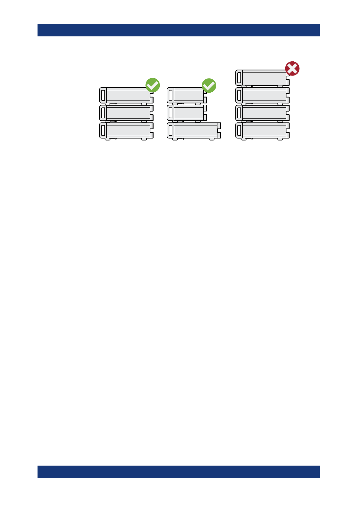
R&S®SMA100B
Getting started
Preparing for use
Left = Stacked correctly, same dimensions
Middle = Stacked correctly, different dimensions
Right = Stacked incorrectly, too many products
NOTICE! Overheating can damage the product.
4.
Prevent overheating as follows:
● Keep a minimum distance of 10 cm between the fan openings of the product
and any object in the vicinity.
● Do not place the product next to heat-generating equipment such as radiators
or other products.
3.1.4.2 Mounting the R&S SMA100B in a rack
To prepare the rack
1. Observe the requirements and instructions in "Setting up the product" on page 20.
NOTICE! Insufficient airflow can cause overheating and damage the product.
2.
Design and implement an efficient ventilation concept for the rack.
To mount the R&S SMA100B in a rack
1. Use an adapter kit that fits the dimensions of the R&S SMA100B to prepare the
instrument for rack mounting.
a) Order the rack adapter kit designed for the R&S SMA100B. For the order num-
ber, see data sheet.
b) Mount the adapter kit. Follow the assembly instructions provided with the
adapter kit.
WARNING! The R&S SMA100B can be heavy, e.g., if fully equipped. Use a lifting
2.
equipment, see also "Lifting and carrying the product" on page 19.
Lift the R&S SMA100B to shelf height.
3. Grab the handles at the front and push the R&S SMA100B onto the shelf until the
rack brackets fit closely to the rack.
28User Manual 1178.3834.02 ─ 09
Page 29

R&S®SMA100B
3.1.5 Considerations for test setup
Getting started
Preparing for use
4. Tighten all screws at the rack brackets with a tightening torque of 1.2 Nm to secure
the R&S SMA100B in the rack.
To unmount the R&S SMA100B from a rack
1. Loosen the screws at the rack brackets.
WARNING! The R&S SMA100B can be heavy, e.g., if fully equipped. Use a lifting
2.
equipment, see also "Lifting and carrying the product" on page 19.
Bring the lifting equipment to shelf height.
3. Remove the R&S SMA100B from the rack.
4. If placing the R&S SMA100B on a bench top again, unmount the adapter kit from
the R&S SMA100B. Follow the instructions provided with the adapter kit.
Cable selection and electromagnetic interference (EMI)
Electromagnetic interference (EMI) can affect the measurement results.
To suppress electromagnetic radiation during operation:
●
Use high-quality shielded cables, especially for the following connector types:
– BNC
Double-shielded BNC cables.
– SMA
Double-shielded SMA cables.
How to: "To connect to Ref In/Ref Out (reference = 1 GHz)" on page 33
– USB
Double-shielded USB cables.
How to: Chapter 3.1.8, "Connecting USB devices", on page 31.
See also Chapter 15.6, "Measuring USB cable quality", on page 752.
– LAN
At least CAT6 STP cables.
How to: Chapter 3.1.7, "Connecting to LAN", on page 30
●
Always terminate open cable ends.
●
Ensure that connected external devices comply with EMC regulations.
Signal input and output levels
Information on signal levels is provided in the data sheet. Keep the signal levels within
the specified ranges to avoid damage to the R&S SMA100B and connected devices.
Preventing electrostatic discharge (ESD)
Electrostatic discharge is most likely to occur when you connect or disconnect a DUT.
29User Manual 1178.3834.02 ─ 09
Page 30

R&S®SMA100B
3.1.6 Connecting to power
Getting started
Preparing for use
NOTICE! Electrostatic discharge can damage the electronic components of the
►
product and the device under test (DUT).
Ground yourself to prevent electrostatic discharge damage:
a) Use a wrist strap and cord to connect yourself to ground.
b) Use a conductive floor mat and heel strap combination.
For safety information, see "Connecting to power" on page 20.
1. Plug the AC power cable into the AC power connector on the rear panel of the
instrument. Only use the AC power cable delivered with the R&S SMA100B.
2. Plug the AC power cable into a power outlet with ground contact.
The required ratings are listed next to the AC power connector and in the data
sheet.
3.1.7 Connecting to LAN
Network environment
Before connecting the product to a local area network (LAN), consider the following:
●
Install the latest firmware to reduce security risks.
●
For internet or remote access, use secured connections if applicable.
●
Ensure that the network settings comply with the security policies of your company.
Contact your local system administrator or IT department before connecting your
product to your company LAN.
●
When connected to the LAN, the product may potentially be accessed from the
internet, which may be a security risk. For example, attackers might misuse or
damage the product.
To connect to LAN
The connector is located on the rear panel.
► Connect the LAN socket via an RJ-45 cable to the LAN.
By default, the R&S SMA100B is configured to use DHCP (dynamic host configuration
protocol) and no static IP address is configured.
If switched on and connected to the LAN, the R&S SMA100B displays the address
information on the screen.
30User Manual 1178.3834.02 ─ 09
Page 31

R&S®SMA100B
3.1.8 Connecting USB devices
Getting started
Preparing for use
Figure 3-1: IP address indication on the screen (example)
See also Chapter 13.7, "Connecting the instrument to the network (LAN)",
on page 414.
You can connect or disconnect all USB devices from the R&S SMA100B during operation.
To connect USB storage devices
USB storage devices, such as memory sticks, allow data transfer from or to the
R&S SMA100B. You can also use them for firmware updates.
► Connect the USB storage device to any of the USB connectors.
To connect USB devices with external power supply
NOTICE! Connected devices with external power supply can feed back current into
1.
the 5 V power supply of the USB interface and thus damage the R&S SMA100B.
Ensure that there is no connection between the positive pole of the power supply
and the +5 V power pin of the USB interface (VBUS).
2. Connect the USB storage device to any of the USB connectors.
To connect a keyboard
► Connect the keyboard to any of the USB connectors.
When connected, the R&S SMA100B detects the keyboard automatically. A detected
keyboard has the default layout English – US.
To connect a mouse
► Connect the mouse to any of the USB connectors.
When connected, the R&S SMA100B detects the mouse automatically.
To connect power sensors
You can connect power sensors of the R&S NRP families to any of the USB connectors.
See Chapter 8.4, "Using power sensors", on page 233.
31User Manual 1178.3834.02 ─ 09
Page 32

R&S®SMA100B
3.1.9 Connecting to RF
Getting started
Preparing for use
The connector is located on the front panel.
If you have the instrument equipped with an option for rear panel connectors, the RF
output connector is on the rear panel.
To prepare for connecting to RF
NOTICE! Damaged or not clean connections can lead to RF insertion loss and mis-
1.
match, and even premature wear of the connectors.
Before connecting to the port, inspect the RF connector visually to check that it is
clean, undamaged and mechanically compatible.
See the application note 1MA99 for information on how to handle and maintain the
RF port, to minimize measurement deviations and ensure its longevity.
NOTICE! Risk of instrument damage. Excessive reverse power or DC voltage at
2.
the RF connector can damage the instrument.
Make sure that signal power and DC limits as given in the data sheet.
3. If the R&S SMA100B is switched on, deactivate the RF output, before connecting
an RF cable to the RF connector.
In the home screen, select the block "Level" > "RF ON > Off".
4. Use a high-quality RF cable that matches the RF connector type.
See "Cable selection and electromagnetic interference (EMI)" on page 29.
To connect to screwable connectors
1. Use a high-quality cable that matches the connector type.
See "Cable selection and electromagnetic interference (EMI)" on page 29.
NOTICE! Risk of instrument damage and connector damage. Excessive tightening
2.
can damage the cables and the connectors. However, if you do not tighten the connectors enough, the measurement results can be inaccurate.
To connect the cable with the connector, proceed as follows:
a) Carefully align the connector of the cable and the connector along a common
axis.
b) Mate the connectors along the common axis until the male pin of the inner con-
nector engages with the female socket of the outer connector.
c) Turn the nut of the outer connector until the connectors are firmly coupled.
d) Torque the nut to the specified limit using a calibrated torque wrench. Hold the
opposite connector part stationary with a spanner.
For torque limits of the most relevant connector types, see Table 3-1.
For more information, see chapter "Handling" of the application note 1MA99.
If your instrument is equipped with a test port adapter, see the application note
1MA100.
32User Manual 1178.3834.02 ─ 09
Page 33

R&S®SMA100B
Getting started
Preparing for use
The connector types listed in this table represent the common connectors provided by
Rohde & Schwarz. It is considered as general information and therefore can contain
connector types that do not apply to your instrument.
See Chapter 3.2.1.11, "RF 50 Ω", on page 41.
Table 3-1: Connector types and torque limits
Type Torque limit Nut opening
N 13.3 1.5 3/4 20
SMA 5 0.56 5/16 8
3.5 mm 8 0.9 5/16 8
2.92 mm 8 0.9 5/16 8
2.4 mm 8 0.9 5/16 8
1.85 mm 8 0.9 5/16 8
1.0 mm 3 0.34 0.236 6
lb-Inch Nm Inch mm
To prevent RF output switch-off
NOTICE! If you set a too high output level without a load connected to the instru-
►
ment, the reverse power can exceed a limit forcing the R&S SMA100B to switch off
the RF output.
Connect a load with sufficient return loss as given in the data sheet.
3.1.10 Connecting to Ref In/Ref Out
The connector is located on the rear panel.
To connect to Ref In/Ref Out (reference < 1 GHz)
For connection, the R&S SMA100B provides BNC connectors.
► To connect the cable with the "Ref In"/"Ref Out" connector, proceed as follows:
a) Carefully align the connector of the cable and the "Ref In"/"Ref Out" connector
along a common axis.
b) Mate the connectors along the common axis until the male pin of the connector
of the cable engages with the female socket of the "Ref In"/"Ref Out" connec-
tor.
To connect to Ref In/Ref Out (reference = 1 GHz)
For connection, the R&S SMA100B provides SMA connectors.
1. Use a high-quality cable that matches the connector type.
See "Cable selection and electromagnetic interference (EMI)" on page 29.
33User Manual 1178.3834.02 ─ 09
Page 34

R&S®SMA100B
Getting started
Preparing for use
NOTICE! Risk of instrument damage and connector damage. Excessive tightening
2.
can damage the cables and the connectors. However, if you do not tighten the connectors enough, the measurement results can be inaccurate.
To connect the cable with the connector, proceed as follows:
a) Carefully align the connector of the cable and the connector along a common
axis.
b) Mate the connectors along the common axis until the male pin of the inner con-
nector engages with the female socket of the outer connector.
c) Turn the nut of the outer connector until the connectors are firmly coupled.
d) Torque the nut to the specified limit using a calibrated torque wrench. Hold the
opposite connector part stationary with a spanner.
For torque limits of the most relevant connector types, see Table 3-1.
For more information, see chapter "Handling" of the application note 1MA99.
Table 3-2: Connector types and torque limits
Type Torque limit Nut opening
N 13.3 1.5 3/4 20
SMA 5 0.56 5/16 8
3.5 mm 8 0.9 5/16 8
2.92 mm 8 0.9 5/16 8
2.4 mm 8 0.9 5/16 8
1.85 mm 8 0.9 5/16 8
1.0 mm 3 0.34 0.236 6
lb-Inch Nm Inch mm
3.1.11 Switching on or off
The following table provides an overview of power states, LEDs and power switch positions.
Table 3-3: Overview of power states
State LED Position of power switch
Off
Standby
gray
orange
[0]
[I]
Ready
green
[I]
To switch on the R&S SMA100B
The R&S SMA100B is off but connected to power. See Chapter 3.1.6, "Connecting to
power", on page 30.
1. Set the switch on the power supply to position [I].
34User Manual 1178.3834.02 ─ 09
Page 35

R&S®SMA100B
Getting started
Instrument tour
The switch is located on the rear panel.
The LED of the [On/Standby] key is orange.
2. Press the [On/Standby] key.
Key and LED are located on the front panel.
The LED changes to green. The R&S SMA100B boots.
When starting for the first time, the R&S SMA100B starts with the default settings.
When restarting the instrument, the settings depend on the instrument configuration before shut-down.
See Chapter 11.4, "Saving and recalling instrument settings", on page 317.
When the instrument is switched on, it automatically monitors main functions. You can
query erroneous functions. In addition to automatic monitoring, you can perform maintenance tasks.
See:
●
Chapter 15.4, "Querying notifications", on page 749
●
Chapter 17.3, "Performing maintenance tasks", on page 761
To shut down the product
The product is in the ready state.
► Press the [On/Standby] key.
The operating system shuts down. The LED changes to orange.
In the standby state, the power switch circuits are active. To deactivate them, disconnect the instrument from the power supply.
To disconnect from power
The R&S SMA100B is in the standby state.
NOTICE! Risk of data loss. If you disconnect the product from power when it is in
1.
the ready state, you can lose settings and data. Shut it down first.
Set the toggle switch on the power supply to position [0].
The LED of the [On/Standby] key is switched off.
2. Disconnect the R&S SMA100B from the power source.
3.2 Instrument tour
This chapter explains the control elements and the connectors of the R&S SMA100B.
The views of the front panel and the rear panel help you to get familiar with the instrument and to perform first steps. For specifications of the interfaces, see the data sheet.
The meanings of the labels on the R&S SMA100B are described in Chapter 1.2,
"Labels on R&S SMA100B", on page 21.
35User Manual 1178.3834.02 ─ 09
Page 36

R&S®SMA100B
3.2.1 Front panel tour
1 2 3 4 5 6 7
Getting started
Instrument tour
This section provides an overview of the control elements at the front panel of the
R&S SMA100B. Most of the connectors are at the rear panel and are described in
Chapter 3.2.2, "Rear panel tour", on page 43.
891011
Figure 3-2: Front panel view of the R&S SMA100B RF Signal Generator with height unit 2HU (option
1 = Utility keys, page 38
2 = Touchscreen, page 37
3 = Function keys, page 38
4 = Navigation controls, page 39
5 = Display keys, page 40
6 = SD card slot, page 40
7 = USB connector, page 40
8 = RF 50 Ω, page 41
9 = Sensor, page 41
10 = Keypad, page 38
11 = On/Standby, page 38
R&S SMAB-B92)
7654321
8 10
9
15 14 13 12 11
Figure 3-3: Front panel view of the R&S SMA100B RF Signal Generator with height unit 3HU (option
R&S SMAB-B93)
36User Manual 1178.3834.02 ─ 09
Page 37

R&S®SMA100B
3.2.1.1 Touchscreen
Getting started
Instrument tour
1 = On/Standby, page 38
2 = Utility keys, page 38
3 = Touchscreen, page 37
4 = Keypad, page 38
5 = Function keys, page 38
6 = Navigation controls, page 39
7 = Display keys, page 40
8 = SD card slot, page 40
9 = USB connector, page 40
10 = Sensor, page 41
11 = RF 50 Ω, page 41
12 = Pulse signal connectors, page 42
13 = LF, page 42
14 = Ext 1/2, page 46
15 = Clock synthesizer connectors, page 42
The screen at the front panel is the graphical user interface. It shows the settings dialogs and parameters, and the current configuration at a glance, see Chapter 3.4.3,
"Understanding the display information", on page 55.
Figure 3-4: Touchscreen
The touch-sensitive panel provides an alternative means of user interaction for quick
and easy handling of the instrument, see Chapter 3.4.2, "Means of manual interaction",
on page 54.
See also:
●
Chapter 3.4, "Instrument control", on page 53, for operating the touchscreen.
●
Chapter 17.1, "Cleaning", on page 761, for instructions on cleaning the screen.
37User Manual 1178.3834.02 ─ 09
Page 38

R&S®SMA100B
3.2.1.2 Utility keys
3.2.1.3 On/Standby
Getting started
Instrument tour
The utility keys set the R&S SMA100B to a defined state, and provide access to basic
settings and information on assistance.
Table 3-4: Utility keys
Utility Key Assigned functions
[Preset] Sets the instrument to a defined state
[Local] Switches from remote control to local (manual) control
[Setup] Accesses the general instrument settings
[Help] Displays context-sensitive help text
The [On/Standby] key switches the instrument from the standby to the ready state or
vice versa.
The LED above the [On/Standby] key indicates the instrument state, see Chap-
ter 3.1.11, "Switching on or off", on page 34.
3.2.1.4 Function keys
Function keys provide access to the most common generator settings and functions.
You can find a detailed description of the corresponding functions in the user manual.
Table 3-5: Function keys
Function key Assigned functions
[Freq] Activates frequency entry.
[Level] Activates level entry.
[Mod on/off] Switches the modulation on and off.
[RF on/off] Switches the RF output on and off.
3.2.1.5 Keypad
The keypad enables you to enter alphanumeric parameters, including the corresponding units. It contains the following keys:
Table 3-6: Keys on the keypad
Type of key Description
Alphanumeric keys Enter numbers and (special) characters in edit dialog boxes.
Decimal point Inserts a decimal point "." at the cursor position.
38User Manual 1178.3834.02 ─ 09
Page 39

R&S®SMA100B
Getting started
Instrument tour
Type of key Description
Sign key Changes the sign of a numeric parameter. In the case of an alphanu-
meric parameter, inserts a "-" at the cursor position.
Unit keys
(G/n dBμV, M/μ μV, k/m mV and
x1 dB(m))
3.2.1.6 Navigation controls
The navigation controls include a rotary knob, navigation keys, and the display keys.
They allow you to navigate within the display or within dialog boxes.
Rotary knob
The rotary knob has several functions:
●
Increments (clockwise direction) or decrements (counterclockwise direction) the
instrument parameter at a defined step width in the case of a numeric entry.
●
Moves the selection, e.g. to a function block in the block diagram
●
Shifts the selection bar within focused areas (e.g. lists).
●
Acts like the [Enter] key, when it is pressed.
●
Opens a context-sensitive menu, when it is pressed and held.
editing keys
These keys add the selected unit to the entered numeric value and complete the entry.
In the case of level entries (e.g. in dB) or dimensionless values, all units
have the value "1" as multiplying factor. Thus, they have the same function as an [Enter] key.
Editing keys enable you to confirm an entry, delete individual characters, or exit the
current operation.
Table 3-7: Editing keys
Type of key Description
[Esc] key Closes all kinds of dialog boxes, if the edit mode is not active. Quits the
edit mode, if the edit mode is active. In dialog boxes that contain a "Cancel" button it activates that button.
For "Edit" dialog boxes the following mechanism is used:
●
If data entry has been started, it retains the original value and
closes the dialog box.
●
If data entry has not been started or has been completed, it closes
the dialog box.
[Enter] key
[Backspace] key Deletes the character to the left of the cursor in editing mode.
Has the same effect as pressing the rotary knob
●
Concludes the entry of dimensionless entries. The new value is
accepted.
●
With other entries, this key can be used instead of the default unit
key.
●
In a dialog box, selects the default or focused element.
●
Calls the next dialog level.
●
Confirms and closes open input windows.
39User Manual 1178.3834.02 ─ 09
Page 40

R&S®SMA100B
Getting started
Instrument tour
Navigation keys
As an alternative to the rotary knob or the touchscreen, you can use the navigation
keys to navigate through dialog boxes, diagrams, or tables.
Table 3-8: Navigation keys
Type of key Description
[Up/Down] Key The [Up] and the [Down] key does the following:
[Left/Right] Key The [Left] and the [Right] key does the following:
3.2.1.7 Display keys
The display keys arrange different windows on the display.
Table 3-9: Display keys
Display key Assigned functions
[Home] Returns to the initial feature screen.
[Next window] Toggles between the entry fields in the taskbar.
[On/Off]
●
In a numeric edit dialog box, increase or decrease the instrument
parameter.
●
In a list, scroll forward and backward through the list entries.
●
In a table, move the selection bar vertically.
●
In windows or dialog boxes with vertical scrollbar, move the scrollbar.
●
In an alphanumeric edit dialog box, move the cursor.
●
In a list, scroll forward and backward through the list entries.
●
In a table, move the selection bar horizontally.
●
In windows or dialog boxes with horizontal scrollbar, move the
scrollbar.
●
Switches highlighted elements or a function block on and off.
●
Switches between two or more settings, e.g. items of selection lists.
At the end of a list, the cursor is set on the first entry again.
[Undo] Reverts the last operation.
[★ (User)] Adds a parameter to the user menu for quick access.
3.2.1.8 SD card slot
Option: R&S SMAB-B85
Slot for removable mass storage.
To prevent from unauthorized removal, the SD card holder includes wholes that provide the opportunity of sealing the SD card. We recommend that you seal the SD card
crosswise.
3.2.1.9 USB connector
Female USB type A connector, to connect devices like a keyboard, a mouse, a memory stick, or the R&S NRP-Z3/Z4 cable for the R&S NRP power sensors.
40User Manual 1178.3834.02 ─ 09
Page 41

R&S®SMA100B
3.2.1.10 Sensor
Getting started
Instrument tour
How to: Chapter 3.1.8, "Connecting USB devices", on page 31
Connector for R&S NRP sensors.
A power sensor is connected to the R&S SMA100B by inserting the male connector. To
disconnect, pull the connector by its sleeve. You cannot disconnect the sensor simply
by pulling at the cable or the rear part of the connector.
The R&S SMA100B supports the use of R&S NRP power sensors in various ways
including the use as a power viewer.
The female connector allows the mechanical connection of 6-pole and 8-pole male
connectors.
It mates with the interface cables R&S NRP-ZK8 and R&S NRP-ZK6, used for connecting R&S NRPxx power sensors, and also with the six-pole push-pull plugs of the
R&S NRP-Zxx series.
However, the signal pair of the common time base clock assigned to the two pins in the
center of the male connectors is not available. These pins are used by
Rohde & Schwarz power meters to synchronize several power sensors.
Further information on connecting and using power sensors, see Chapter 8.4.1, "Con-
necting R&S NRP power sensors to the R&S SMA100B", on page 233, Chapter 8.4.4,
"NRP-Z power analysis", on page 245, Chapter 8.4.2, "NRP sensor mapping",
on page 234, Chapter 8.4.4, "NRP-Z power analysis", on page 245 and Chapter 8.3,
"User correction", on page 221.
3.2.1.11 RF 50 Ω
Output of the RF signal.
The connector type depends on the installed frequency option.
Table 3-10: RF connector types of the frequency options
Installed RF frequency
option
R&S SMAB-B103 N female f
R&S SMAB-B106
R&S SMAB-B112 PC 2.92 mm female
R&S SMAB-B120
R&S SMAB-B131
R&S SMAB-B140(N)
Connector type Frequnecy range
≤ 6 GHz
max
f
≤ 40 GHz
max
Instrument equipped with interchangeable
PC 2.92 mm test port adapter.
R&S SMAB-B150(N) PC 1.85 mm female
R&S SMAB-B167(N)
Instrument equipped with PC 1.85 mm interchangeable female/female wear and tear adapter.
f
≤ 67 GHz
max
41User Manual 1178.3834.02 ─ 09
Page 42

R&S®SMA100B
3.2.1.12 Pulse signal connectors
Getting started
Instrument tour
The PC 1.85 mm male connector for up to 67 GHz comes with a protective 1.85 mm
female adapter to prevent the sensitive connector from damage.
It is available as a spare part, and can be replaced if damaged. Contact your
Rohde & Schwarz support center or www.rohde-schwarz.com/support for information.
How to: Chapter 3.1.9, "Connecting to RF", on page 32
Pulse Sync
Output signal for synchronizing the pulse generator signal. The synchronization signal
is generated at the beginning of each pulse. For double-pulse generation, the synchronization signal is generated at the beginning of the first pulse.
Pulse Video
Output of the internal pulse generator signal or the looped through pulse signal from
Pulse Ext connector (video signal).
See Chapter 5.4.1, "Pulse modulation settings", on page 84.
Pulse Ext
Input for an external pulse modulation signal or an external trigger/gate signal for the
pulse generator.
3.2.1.13 LF modulation connectors
LF
Output for internal LF generator signal.
See the data sheet and in the user manual, section Chapter 5, "Analog modulations",
on page 81.
Ext
Input for external analog modulation signals.
See Chapter 5, "Analog modulations", on page 81.
3.2.1.14 Clock synthesizer connectors
Clk Syn/Clk Syn N
Connectors for output of the clock synthesizer signal, or the inverted signal.
42User Manual 1178.3834.02 ─ 09
Page 43

R&S®SMA100B
3.2.2 Rear panel tour
Getting started
Instrument tour
This section provides an overview of the connectors at the rear panel of the instrument.
For technical data of the connectors, refer to the data sheet.
1 2 3 4 5 6 7 8 9 10 11 12 13
16171819
Figure 3-5: R&S SMA100B rear panel with height unit 2HU (option R&S SMAB-B92)
1 = Serial number (six digits in the string 1419.8888.02-<serial number>-<checksum>)
2 = IEC 625/IEEE 488, page 44
3, 5 = USB/USB In, page 44
4 = LAN, page 44
6, 7 = Ref In/Ref Out, page 45
8 = V/GHz X-Axis, page 44 and Z-Axis, page 44
9 = Stop, page 45
10 = EFC, page 45
11 = Marker User1, page 45
12 = Inst Trig, page 45
13 = Signal Valid, page 45
14 = Clk Syn/Clk Syn N, page 42
15 = Pulse Sync, page 45, Pulse Video, page 42 and Pulse Ext, page 42
16 = LF, page 42
17 = Ext 1/2, page 46
18 = AC power supply connector and switch, page 46
19 = RF, page 46
1 2 3 4 5 7 8 9 10 131211
6
1415
1
2
141516171819
Figure 3-6: Rear panel view of the R&S SMA100B RF Signal Generator with height unit 3HU (option
1 = Serial number (six digits in the string 1419.8888.02-<serial number>-<checksum>)
2 = IEC 625/IEEE 488, page 44
3, 5 = USB/USB In, page 44
4 = LAN, page 44
6, 7 = Ref In/Ref Out, page 45
R&S SMAB-B93)
43User Manual 1178.3834.02 ─ 09
Page 44

R&S®SMA100B
3.2.2.1 Connectors
Getting started
Instrument tour
8 = V/GHz X-Axis, page 44 and Z-Axis, page 44
9 = Stop, page 45
10 = EFC, page 45
11 = Marker User1, page 45
12 = Inst Trig, page 45
13 = Signal Valid, page 45
14 = Clk Syn/Clk Syn N, page 42
15 = Pulse Sync, page 45, Pulse Video, page 42 and Pulse Ext, page 42
16 = LF, page 42
17 = Ext 1/2, page 46
18 = AC power supply connector and switch, page 46
19 = RF, page 46
IEC 625/IEEE 488
Option: R&S SMAB-B86
General purpose interface bus (GPIB) interface for remote control of the instrument.
The interface is in compliance with the standards IEC 625, IEEE 488 and SCPI.
Use this interface to connect a computer for remote control of the R&S SMA100B. To
set up the connection, use high-quality shielded cables. See "Cable selection and elec-
tromagnetic interference (EMI)" on page 29.
See also Chapter A.2.1, "GPIB-Bus interface", on page 779 and Chapter 13, "Network
operation and remote control", on page 378.
USB/USB In
●
Female USB (universal serial bus) 2.0 connector of type A (host USB), to connect
devices like a keyboard, a mouse, a memory stick, or the R&S NRP-Z3/Z4 cable
for the R&S NRP power sensors
●
Option: R&S SMAB-B86
Female USB 3.0 connector of type Micro-B (USB In), for example, for remote control.
How to: Chapter 3.1.8, "Connecting USB devices", on page 31
LAN
RJ-45 connector to connect the R&S SMA100B to a LAN for remote control, remote
operation, and data transfer.
How to: Chapter 3.1.7, "Connecting to LAN", on page 30
V/GHz X-Axis
Output of a voltage ramp:
●
"V / GHz": the voltage is proportional to the frequency.
●
"X-Axis": output of a voltage ramp for the X deflection of an oscilloscope or an XY
recorder.
Z-Axis
Output of a voltage pulse, e.g. for the combined blanking and marker generation of network analyzers.
44User Manual 1178.3834.02 ─ 09
Page 45

R&S®SMA100B
Getting started
Instrument tour
Stop
Input and output for stopping the sweep in all modes.
This connector is bidirectional. Used as:
●
"Input": enables you to stop a sweep triggered by an external network analyzer.
●
"Output": enables the R&S SMA100B to stop the sweep of an external network
analyzer.
Marker User1
Output signal for marker or trigger signal.
Signal Valid
Output signal that determines the valid signal times (valid level and frequency) for all
analog modulations.
Inst Trig
BNC connector for input of external trigger signals. The signals trigger sweeps and list
mode.
See Chapter 7.1, "Signal generation and triggering in the sweep and list modes",
on page 173.
EFC
BNC connector for input of an EFC (external frequency control) signal for electronic
tuning of the internal reference frequency.
See Chapter 9, "Reference oscillator", on page 294.
Ref In/Ref Out
Input/output for external reference signal.
BNC connectors for reference signals from 1 MHz to 100 MHz.
SMA connectors for 1 GHz reference signals.
How to: Chapter 3.1.10, "Connecting to Ref In/Ref Out", on page 33
Clk Syn/Clk Syn N
Connectors for output of the clock synthesizer signal, or the inverted signal.
Pulse Ext
Input for an external pulse modulation signal or an external trigger/gate signal for the
pulse generator.
Pulse Video
Output of the internal pulse generator signal or the looped through pulse signal from
Pulse Ext connector (video signal).
See Chapter 5.4.1, "Pulse modulation settings", on page 84.
Pulse Sync
Output signal for synchronizing the pulse generator signal. The synchronization signal
is generated at the beginning of each pulse. For double-pulse generation, the synchronization signal is generated at the beginning of the first pulse.
45User Manual 1178.3834.02 ─ 09
Page 46

R&S®SMA100B
Getting started
Trying out the instrument
LF
Output for internal LF generator signal.
See the data sheet and in the user manual, section Chapter 5, "Analog modulations",
on page 81.
Ext 1/2
Inputs for external analog modulation signal.
See Chapter 5, "Analog modulations", on page 81.
AC power supply connector and switch
Mains power switch for performing the following tasks:
●
Connecting the internal power supply to the power source
●
Disconnecting the internal power supply from the power source
How to: Chapter 3.1.6, "Connecting to power", on page 30.
RF
Rear panel connector for the RF signal. This connector is for use of the instrument in a
19" rack.
How to:
●
Chapter 3.1.4.2, "Mounting the R&S SMA100B in a rack", on page 28
●
Chapter 3.1.9, "Connecting to RF", on page 32
3.3 Trying out the instrument
This chapter introduces the first steps with the R&S SMA100B. It shows how to operate and configure the instrument using simple examples. The complete description of
the functionality and its usage is given in the R&S SMA100B user manual. Basic instrument operation is described in Chapter 3.4, "Instrument control", on page 53.
Prerequisites
The instrument is set up, connected to the power supply, and started up as described
in Chapter 3.1, "Preparing for use", on page 26.
The first signal generation tasks explain how to generate an unmodulated signal, to
configure the RF signal output, and how you can vary the RF frequency and level in
sweep mode.
The instrument is manually operated via the touchscreen. Try out the following:
● Generating an unmodulated carrier........................................................................ 46
● Generating an RF frequency sweep signal.............................................................49
● Saving and recalling settings.................................................................................. 51
3.3.1 Generating an unmodulated carrier
We start to generate a simple unmodulated signal. In this example, the R&S SMA100B
can be in its minimal configuration.
46User Manual 1178.3834.02 ─ 09
Page 47

R&S®SMA100B
Getting started
Trying out the instrument
1. On the R&S SMA100B front panel, press the [Preset] key to set a defined initial
instrument state.
2. Set the frequency:
a) In the "Status Bar", tap the "Frequency" field.
b) On the on-screen keypad, enter "6" and press the "GHz" key.
The on-screen key pad closes and the frequency value is displayed.
3. To set the signal level, tap the "Level" field and enter the level in the same way.
4. To activate RF signal output, select "Level" > "RF On" in the tile diagram.
47User Manual 1178.3834.02 ─ 09
Page 48

R&S®SMA100B
Getting started
Trying out the instrument
The blue colored "RF On" icon indicates that the RF output is activated.
The R&S SMA100B provides the 6 GHz signal at the RF A connector at the front
panel.
Figure 3-7: Generating an unmodulated signal
Alternative ways to access the instrument functions
To fulfill the same task, you can also use the front panel keys or the setting parameters
provided in the frequency and level dialogs.
Try out the settings dialogs
1. In the "Frequency" tile, select "Frequency...".
a) In the "RF Frequency" tab, tap the "Frequency" field.
b) Set the frequency via the on-screen keypad.
2. Access the "RF Level" dialog via the "Level" tile.
a) In the "RF Level" tab, select "Amplitude".
b) Set the amplitude (level) via the on-screen keypad.
3. Select "RF State > On" to activate the RF signal generation.
See Chapter 4, "RF signal configuration", on page 64.
Try out the front panel keys
► Use the [Freq], [Level], and [RF on/off] key on the front panel.
48User Manual 1178.3834.02 ─ 09
Page 49

R&S®SMA100B
3.3.2 Generating an RF frequency sweep signal
Getting started
Trying out the instrument
Connect RF of the R&S SMA100B to a signal analyzer, for example R&S®FSW, to display the generated signal.
For the required settings of the signal analyzer, refer to its user manual or its online
help.
The "Sweep" operating mode allows you to generate an RF signal with periodically
varying frequencies or amplitudes.
This example deals with an RF signal with varying frequency and constant level. To
configure the sweep, you need to determine a defined start and end frequency with
constant time intervals between the frequency steps.
The sweep function does not require specific options.
1. On the front panel, press the [Preset] key to set a defined initial instrument state.
2. Set the signal output level, if required, e.g. set "Level > -25 dBm".
3. In the tile diagram, select "Sweep" > "Frequency Sweep".
4. In the "General" tab:
a) Select "Mode > Auto" to run the sweep continuously.
b) Select "Shape > Sawtooth" to set the waveform shape of the sweep signal.
c) Select "Spacing > Linear", to determine the calculation method for the fre-
quency shift of a step.
d) Set "Dwell Time > 15.0 ms", to determine the time interval of the sweep steps.
5. Select the "Frequency Range" tab.
49User Manual 1178.3834.02 ─ 09
Page 50

R&S®SMA100B
Getting started
Trying out the instrument
a) Set "Start Freq > 200 MHz" and "Stop Freq > 600 MHz" to determine the fre-
quency sweep range.
b) Set the step width "Step Lin > 10.0 MHz" to determine the width for a frequency
step.
6. In the "General" tab, activate the frequency sweep with "State > On".
7. Close the sweep dialog.
(Alternatively, tap the "Home" button to minimize the dialog. The R&S SMA100B
indicates the "Sweep" dialog as active dialog in the task bar.)
8. To activate the RF signal output, select "Level" > "RF On".
Figure 3-8: Generating a frequency sweep signal
The frequency field in the status bar indicates the continuously changing frequency,
i.e. the running sweep.
50User Manual 1178.3834.02 ─ 09
Page 51

R&S®SMA100B
3.3.3 Saving and recalling settings
Getting started
Trying out the instrument
To restore the results of our measurements later, we save the instrument settings in a
file.
To save the instrument settings in a file
We assume, a test configuration as described in Chapter 3.3.2, "Generating an RF fre-
quency sweep signal", on page 49.
1. Press the [Setup] key on the front panel.
2. In the "Setup" menu, select "Settings > Save/Recall".
3. In the "Save/Recall" dialog, select "Operation Mode > Save".
4. Tap the "Filename", use the on-screen keyboard, and enter MyTestSignal.
5. Tap the "Save" button.
The file MyTestSignal.savrcltxt is stored in the default directory /var/user/.
To load saved instrument settings
You can restore the settings to the instrument at any time using the settings file.
1. Press the [Preset] button to restore the default instrument settings so you can
check that the stored user settings are restored afterwards.
2. Press the [Setup] key on the front panel.
3. In the "Setup" menu, select "Settings > Save/Recall".
51User Manual 1178.3834.02 ─ 09
Page 52

R&S®SMA100B
Getting started
Trying out the instrument
4. In the "Save/Recall" dialog, select "Operation Mode > Recall".
Navigate to the directory the file is saved in and select the MyTestSignal file.
5. Tap the "Recall" button.
All instrument settings are restored and the display resembles Chapter 3.3.2, "Gen-
erating an RF frequency sweep signal", on page 49, which shows the instrument
display right before the settings were saved.
How to display all parameters with values different to their preset values
When you load a file to your instrument, you do not have enough information on the
changed settings. In such case, it is useful to visualize all parameters that have been
changed from their default state.
Try out the following:
●
Touch and hold a spot in the tile diagram for at least 1 second to access the context-sensitive menu.
●
Select "Mark All Parameters Changed from Preset".
52User Manual 1178.3834.02 ─ 09
Page 53

R&S®SMA100B
●
All changed parameters are highlighted.
Getting started
Instrument control
See also
Chapter 11, "File and data management", on page 308.
3.4 Instrument control
This chapter provides an overview on how to work with the R&S SMA100B.
It covers the following topics:
● Possible ways to operate the instrument................................................................ 54
● Means of manual interaction...................................................................................54
● Understanding the display information....................................................................55
● Accessing the functionality......................................................................................58
● Entering data...........................................................................................................59
53User Manual 1178.3834.02 ─ 09
Page 54

R&S®SMA100B
3.4.1 Possible ways to operate the instrument
Getting started
Instrument control
● Getting information and help...................................................................................61
● Remote control........................................................................................................62
● Remote operation over VNC...................................................................................63
There are three ways to operate the R&S SMA100B:
●
Manual operation:
Use the touchscreen, hard keys and rotary knob, or an optional mouse and/or keyboard.
The description under Chapter 3.4, "Instrument control", on page 53 shows how to
operate the instrument manually.
●
Remote control:
Create programs to automatize repeating settings, tests and measurements. The
instrument is connected to a computer running the program.
This way of operation is described in Chapter 13, "Network operation and remote
control", on page 378.
●
Remote operation from a computer:
Remote monitoring and control of the instrument from a connected computer is
based on the common cross-platform technology VNC (Virtual Network Computing). On the remote computer, any standard web browser (supporting Java) or a
dedicated VNC client (like Ultr@VNC) can be used. See also Chapter 3.4.8,
"Remote operation over VNC", on page 63.
3.4.2 Means of manual interaction
For the manual interaction with the R&S SMA100B, you have several methods that you
can use as an alternative to perform a task:
●
Touchscreen:
Touchscreen operation is the most direct way to interact. Almost all control elements and actions on the screen are based on the standard operating system concept. You can tap any user interface element to set parameters in dialog boxes,
enter data, scroll within a dialog etc., as if you work with a mouse pointer.
Tapping the screen works like clicking mouse buttons:
– Touch quickly = click: Selects a parameter or provokes an action.
– Touch and hold = right-click: Opens a context-sensitive menu.
– Touch and swipe = drag: Scrolls through the contents of a display element
larger than the screen, e.g. a list or a table.
●
Function keys and rotary knob:
The front panel provides nearly all functions and controls to operate the instrument
in the classic way, without touchscreen.
●
Optional mouse and/or keyboard:
These devices work like known from PCs. The navigation keys on the front panel
correspond to the keys on the keyboard.
54User Manual 1178.3834.02 ─ 09
Page 55

R&S®SMA100B
3.4.3 Understanding the display information
Getting started
Instrument control
This manual describes the manual interaction with the instrument via the touchscreen.
It mentions the alternative methods using the keys on the instrument or the on-screen
keypads if it deviates from the standard operating procedures. The usage of the touchscreen and navigation keys is described in Chapter 3.4.4, "Accessing the functionality",
on page 58.
Throughout the manual, the term "select" refers to any of the following methods:
●
Using a finger on the touchscreen
●
Using a mouse pointer in the display
●
Using a key on the instrument or on a keyboard
The home screen of the R&S SMA100B displays all main settings and generator
states, divided into three main operation areas.
1 2
3
Figure 3-9: Home screen
1 = Taskbar/softkey bar with "Home" and "System Config" key
2 = Status bar
3 = Tile diagram
● Status bar................................................................................................................56
● Tile diagram............................................................................................................ 56
● Taskbar....................................................................................................................56
● Additional display characteristics............................................................................ 57
55User Manual 1178.3834.02 ─ 09
Page 56

R&S®SMA100B
3.4.3.1 Status bar
3.4.3.2 Tile diagram
Getting started
Instrument control
The status bar at the top of the screen indicates the RF frequency and the level of the
output signal provided to the DUT. You can set both parameters directly here.
The tile diagram is the main entry to the settings of the R&S SMA100B.
Tile Access to:
"Modulation"
"System Config"
"Sweep"
"Frequency"
"Level"
"Clk Syn / Pow Sens"
1)
requires additional options
3.4.3.3 Taskbar
The "Taskbar" shows a home and an info button, and assigns a labeled button whenever you open a dialog. If more dialogs are open than the taskbar can display, touch
and swipe the taskbar to scroll up and down.
●
Analog and stereo1), and pulse1) modulation settings
●
Built in LF generator
●
"Save/Recall": settings for saving and loading instrument configurations
●
"Remote access": Network and emulation settings.
●
"Setup": general system configuration
●
Frequency and level sweeps
●
List mode
●
RF frequency and phase
●
Reference frequency
●
RF level
●
Attenuator
●
Automatic level control
●
User correction
●
Clock synthesis
●
Power sensors
1)
The buttons shown in the following example represent the variants.
Table 3-11: Example of buttons in the taskbar
"Home" button
Returns to the home screen.
"Busy" indicator
Indicates a running process.
"User Menu"
Lists parameters that can be defined for quick access.
56User Manual 1178.3834.02 ─ 09
Page 57

R&S®SMA100B
3.4.3.4 Additional display characteristics
Getting started
Instrument control
Shows the current remote access connections when the instrument is remotely controlled.
Tip: An indicator in the "System Config" tile shows the current remote control status.
R&S NRP power sensors
Shows a connected external power sensor. The button displays the current readings
when the sensor is active.
Active dialogs
Indicates the dialog name of each active dialog in a separate button.
"Info" key
Provides access to status and error messages.
Note: The warning symbol signifies a permanent error message.
The following section provides a short insight on the indication of the screen in general,
and significant elements that you see under specific operating modes, in dialogs or settings.
●
Appearance of active elements
– Active elements like On/Off switches, state buttons have a blue background.
– Selected elements are framed or highlighted orange.
– Inactive elements are gray.
●
On-Screen keypads
As additional means of interacting with the instrument without having to connect an
external keyboard, either a numerical or alphanumerical on-screen keypad appears
when you activate an entry field (see Chapter 3.4.5, "Entering data", on page 59).
●
Info line
The "Info line" shows brief status information and error messages. It appears when
an event generates a message. If selected, the R&S SMA100B shows information
on static errors and the error history.
●
Key parameters indicated in tab labels
Most dialogs are divided into tabs with logically grouped parameters. The tab label
expresses the content and can also contain status indicators or the set value of a
key parameter.
●
Scroll bar handle
An arrow icon that appears when you touch a scroll bar helps you to scroll in a dialog or list.
If no scrollbar handle appears, you can touch and swipe an element to scroll up
and down.
57User Manual 1178.3834.02 ─ 09
Page 58

R&S®SMA100B
Getting started
Instrument control
●
Progress indicators
A busy icon indicates a currently running process. If a process takes some time, a
progress bar shows the current state.
●
Context-sensitive menus
Within the entire screen display, including single parameters, you can access context-sensitive menus that provide some additional functions.
3.4.4 Accessing the functionality
All functionalities are provided in dialog boxes as known from computer programs. You
can control the instrument intuitively with the touchscreen. This section provides an
overview of the accessing methods.
The instrument's functions and settings can be accessed by selecting one of the following elements:
●
System and function keys on the front panel of the instrument
●
Taskbar/softkeys on the touchscreen
●
Context-sensitive menus for specific elements on the touchscreen, or with the
rotary knob (press and hold).
●
Elements on the status bar in the touchscreen
●
Displayed setting on the touchscreen, that means block diagram and all settings
available in dialogs.
To open a dialog box
► Perform one of the following actions:
58User Manual 1178.3834.02 ─ 09
Page 59

R&S®SMA100B
Getting started
Instrument control
● Tap the required tile, and then the menu entry.
● Tap the minimized view (button) on the taskbar.
Some of the utility keys access a dedicated dialog, too.
To minimize a dialog box
1. To return to the home screen, tap the "Home" button.
2. To switch to another dialog, press the [Next Window] button.
To close a dialog box
To close a dialog box, you have the same controls as you know from computers or
devices with touchscreen.
► Perform one of the following actions:
● Tap the "Close" icon in the upper right corner.
● Press the [Esc] key on the front panel.
● Drag and drop a minimized dialog from the taskbar to the tile diagram.
To select an option in a dialog box
► Tap the required option.
3.4.5 Entering data
Some parameters have their own key on the front panel.
For data input in dialog boxes, the instrument provides on-screen keypads for entering
numeric and alphanumeric values. Thus, you can always set the parameters via the
touchscreen, the front panel, or an external keyboard.
To correct an entry
1. Using the arrow keys, move the cursor to the right of the entry you want to delete.
2. Press the [Backspace] key.
3. Deletes the entry to the left of the cursor.
4. Enter your correction.
To complete the entry
► Press the [Enter] key or the rotary knob.
To abort the entry
► Press the [Esc] key.
The dialog box closes without changing the settings.
59User Manual 1178.3834.02 ─ 09
Page 60

R&S®SMA100B
3.4.5.1 Entering numeric parameters
Getting started
Instrument control
To enter values with the on-screen keypad
For numeric settings, the instrument displays the numeric keypad. The units specified
correspond to the units of the parameter.
1. Enter the numeric value.
Tip: For quick entry, you can enter a value in exponential representation, e.g. 1e7
for 10000000.
2. Tap the unit button to complete the entry.
The unit is added to the entry.
Tip: For quick unit change, you can enter shortcuts, e.g. for a frequency value
1e8h for 100 MHz.
For an overview of shortcuts supported by the R&S SMA100B, see Chapter C,
"Unit shortcuts", on page 782.
3. If the parameter does not require a unit, confirm the entered value by pressing
"Enter".
To enter values by using the front panel controls
1. Change the currently used parameter value by using the rotary knob or the [Up/
Down] keys.
2. If the parameter does not require a unit, confirm the entered value by pressing the
[Enter] key or any of the unit keys.
The instrument highlights the editing line to confirm the entry.
If you edit numeric data in tables, the entry field must be in edit mode: Press [Enter], or
the rotary knob to activate the edit mode.
3.4.5.2 Entering alphanumeric parameters
If a field requires alphanumeric input, you can use the on-screen keyboard to enter letters and (special) characters.
3.4.5.3 Undo and redo actions
Accessed via the context-sensitive menus, "Undo" allows you to restore one or more
actions on the instrument. Depending on the available memory, the "Undo" steps can
restore all actions.
60User Manual 1178.3834.02 ─ 09
Page 61

R&S®SMA100B
3.4.6 Getting information and help
Getting started
Instrument control
"Redo" restores a previously undone action.
In some dialog boxes, graphics are included to explain the way a setting works.
For further information, you can use the following sources:
●
Tooltips give the value range of the parameter.
●
The context help provides functional description on a setting.
●
The general help explains a dialog box, provides instructions, and general information.
To display context help
► To access a help topic, perform one of the following:
a) Tap and hold the parameter for which you need information and tap "Help" in
the context menu.
b) Tap the parameter and press the [Help] key.
The "Help" dialog opens. You can browse the help for further information.
Contents of the help dialog box
The help dialog box covers two main areas:
●
"Contents" - contains a table of help contents
●
"Topic" - contains a specific help topic
The help system also provides an "Index" and a "Find" area, and "Zoom" functions that
are accessed via the corresponding buttons.
61User Manual 1178.3834.02 ─ 09
Page 62

R&S®SMA100B
Getting started
Instrument control
To open general help
► Press the yellow [Help] key on the front panel.
If a dialog box is opened, the help topic for the current tab is shown. Otherwise the
"Contents" page appears.
Navigating in the table of contents and in the help topics
1. To move through the displayed contents entries, tap on an entry and scroll or use a
connected mouse or the [Up/Down] keys.
Entries with a plus sign contain further entries.
2. To display a help topic, tap on the topic name or double-click the topic name or
press the [Enter] key.
3. To follow a cross-reference, tap on the link text.
4. To return to the previous page, select "Back".
This function scrolls back all steps you have performed before.
5. Use the "scroll bars" to shift the visible section of content shown.
6. To maximize the "Topics" area, tap the "Hide Contents Tree" button to hide the contents tree.
Using the index
1. Select the "Index" button.
2. Enter the first characters of the topic you are interested in.
The entries starting with these characters are displayed.
3. Tap on the index entry.
The corresponding help topic is displayed.
3.4.7 Remote control
In addition to working with the R&S SMA100B interactively, located directly at the
instrument, it is also possible to operate and control it from a remote PC.
The R&S SMA100B supports various methods for remote control:
●
Connecting the instrument to a LAN (see Chapter 3.1.7, "Connecting to LAN",
on page 30)
●
Using the LXI browser interface in a LAN
●
Connecting a PC via the IEC-bus (IEEE 488) interface
●
Remote control via the USB interface
For remote control over LAN or USB, you can use the R&S VISA (Virtual Instrument
Software Architecture) library provided for download at the Rohde & Schwarz website
http://www.rohde-schwarz.com/rsvisa.
62User Manual 1178.3834.02 ─ 09
Page 63

R&S®SMA100B
3.4.8 Remote operation over VNC
Getting started
Instrument control
How to configure the remote control interfaces is described in Chapter 13, "Network
operation and remote control", on page 378.
The VNC is an application which can be used to access and control the instrument
from a remote computer through a LAN connection. While the instrument is in operation, the instrument screen contents are displayed on the remote computer, and VNC
provides access to all applications, files, and network resources of the instrument.
Thus, remote operation of the instrument is possible.
Instrument control from a remote computer
To access the basic utility functions of the R&S SMA100B, perform a right mouse click
the block diagram and select "Key Emulation".
A key panel to the right of the block diagram gives access to the utility functions provided by the front panel keys.
The VNC is an add-on program, included in operating system Linux/Unix, and available
as a free-of-charge download on the internet.
For more information, refer to Chapter 13.10, "Operating the R&S SMA100B remotely
using VNC", on page 439.
63User Manual 1178.3834.02 ─ 09
Page 64

R&S®SMA100B
4 RF signal configuration
RF signal configuration
The R&S SMA100B signal generator generates RF signals with outstanding spectral
purity within the frequency range from 8 kHz up to 20 GHz and with adjustable signal
level over a wide range.
In addition to these real-time CW signals, you can generate RF signals from predefined
lists and sweep signals that vary according to the frequency or amplitude curves.
You can also apply versatile analog modulation types with definable characteristics.
The variably adjustable output level due to the built-in attenuator, allows you to vary the
RF signal level over the full level range. Several methods enable you to improve the
signal performance and to optimize the signal quality for the particular application, or to
increase the accuracy and reliability of the generated RF signal.
The R&S SMA100B supports R&S NRP power sensors, e.g. to monitor the output level
of the generator or to determine the level correction values for user correction lists.
Signal modes and characteristics
The R&S SMA100B generates unmodulated or analog modulated RF signals. You can
output the signal in fixed mode or as a signal with periodically varying frequencies or
amplitudes.
Signal modes for RF signal generation:
●
Unmodulated signal
Generates an unmodulated continuous wave (CW) of constant frequency and
amplitude.
For information on the signal frequency and level settings and an example on how
to configure a simple CW signal, see:
– Chapter 4.5, "RF frequency settings", on page 71
– Chapter 4.6, "RF level settings", on page 74
– Chapter 3.3.1, "Generating an unmodulated carrier", on page 46
●
Analog modulated signal
Modulates the signal with an analog signal and generates amplitude, phase, frequency and pulse modulation.
See Chapter 5, "Analog modulations", on page 81.
The R&S SMA100B allows you to provide the RF signal with constant or varying frequencies and/or amplitudes at the output:
●
Constant frequency and level (CW/Fixed mode)
The RF output signal has the set frequency and level.
●
Varying frequency and/or level
– Sweep mode
An RF or LF frequency and RF level sweep signal, processed continuously,
step-by-step or individually and with selectable trigger modes. You can only run
one sweep at a time.
– List mode
64User Manual 1178.3834.02 ─ 09
Page 65

R&S®SMA100B
4.1 Activating RF signal output
RF signal configuration
How to set the frequency and level
The RF signal is based on a list of predefined frequency and level values pairs
and step widths.
See Chapter 7, "List and sweep mode", on page 171.
By default, the RF output signal is deactivated.
To activate the RF output signal
1. Configure the RF signal as required.
Set, for example, the frequency and level values.
2. Activate the RF output in one of the following ways:
a) Select "Level" > "RF ON" > "On"
b) Press the [RF on/off] key at the front panel.
When activated, the "RF On" icon in the "Level" tile turns blue.
RF State/RF ON............................................................................................................65
RF output impedance....................................................................................................65
RF State/RF ON
Activates or deactivates the RF output.
Acts as the [RF on/off] key.
Remote command:
:OUTPut<hw>[:STATe] on page 490
RF output impedance
You can query the impedance of the RF output.
Remote command:
:OUTPut<hw>:IMPedance? on page 491
4.2 How to set the frequency and level
The simplest form of the RF signal is a continuous wave (CW) of constant frequency
and amplitude. The RF signal is defined by its frequency, level and phase.
To configure the RF signal.
1. Use one of the following:
65User Manual 1178.3834.02 ─ 09
Page 66

R&S®SMA100B
RF signal configuration
How to set the frequency and level
a) In the home screen select:
● "Frequency" and "Level" in the status bar
● "Frequency" in the "Frequency" tile
● "Level" in the "Level" tile
● "Phase" in the "Frequency" tile
b) On the front panel:
● Press the [Freq] key
● Press the [Level] key
2. Enter the values as required.
The R&S SMA100B indicates the frequency and level settings in the status bar of the
home screen, and shows active functions and parameters of the RF signal in the "Frequency" and "Level" tiles.
See "RF frequency and level display with a downstream instrument" on page 66.
RF frequency and level display with a downstream instrument
If your test setup includes a downstream instrument, you can enter the parameter of
the downstream instrument in the frequency or level settings dialog of the
R&S SMA100B. Examples of downstream instruments are mixers, frequency multipliers, amplifiers or attenuators and of their corresponding major parameters offset, multiplier, amplitude. The R&S SMA100B generates the signal without the downstream
parameters, but considers all additional parameters concerning the frequency and
level.
Example parameters that affect the frequency and level:
●
Frequency offset
●
Multiplication factor
●
User correction
Any of these cases are indicated by a dedicated icon, displayed in the "Frequency" or
"Level" tile, depending on the affected parameter.
Figure 4-1 illustrates the calculation of the "Frequency" and "Level" values, displayed
in the status bar.
Figure 4-1: Frequency and Level display vs frequency and level at the RF output
66User Manual 1178.3834.02 ─ 09
Page 67

R&S®SMA100B
RF signal configuration
Phase continuous frequency
fRF, Level
f
, Level
RF Out
Out
n*f = Multiplication factor ("RF > RF Frequency > Multiplier")
Δf = Frequency offset ("RF > RF Frequency > Offset")
ΔLevel = Power offset ("RF > RF Level > Offset")
Calculation of fRF and Level
●
fRF =n*f
●
LevelRF = Level
= Frequency and level ("Status bar > Frequency and Level") at the output of the downstream
RF
instrument, see also Calculation of fRF and LevelRF)
= Frequency and level at the output connector [RF] ("RF > RF Frequency > Frequency" and
RF
"RF > RF Level > Amplitude")
RF
+ Δf
RF Out
+ ΔLevel
RF Out
4.3 Phase continuous frequency
The R&S SMA100B enables you to generate a phase continuous RF signal over a certain frequency range. In this mode, the output sine wave signal shows no phase discontinuity or glitch when changing the frequency, e.g in sweep mode.
At frequency changes, the switching transitions (intermediate frequencies) cause
spurs. The spurs are due to adjustments in the synthesizer, e.g. adjusting the settings
of dividers, filters, phase detectors can lead to phase discontinuities.
The phase continuous mode freezes the settings of the synthesizer components which
can generate phase discontinuities when adjusted. The R&S SMA100B performs the
frequency changes with the fine resolution synthesizer. The result is a phase continuous change from one frequency to another without transients.
The available frequency range for continuous-phase signal generation is determined
by the fine resolution synthesizer used. The frequency range varies according to the
RF frequency set at the time you activate phase continuous mode.
Equipped with the ultra low phase noise option (R&S SMAB-B711), the R&S SMA100B
enables you to select between two frequency ranges, either to achieve a higher signal
quality or an especially wide frequency range.
4.3.1 How to generate a phase continuous RF signal
To achieve an output sine wave signal with no phase discontinuity or glitch when
changing the frequency, e.g. in RF frequency sweep mode, you can use the phase
continuous mode provided by the instrument.
Activating frequency or phase modulation deactivates phase continuous mode and
vice versa.
To select the phase continuous frequency mode
The folowing example requires, that the instument is equipped with the option
R&S SMAB-B711.
67User Manual 1178.3834.02 ─ 09
Page 68

R&S®SMA100B
RF signal configuration
RF connector settings
Before setting the parameters and activating the phase continuous mode, turn off acitive sweeps.
1. If the "RF Frequency Sweep" is running, select "Sweep" > "RF Frequency Sweep".
2. Turn off "State".
3. On the home screen, select "Frequency" > "Phase".
4. Turn off "Phase Continuous Active", if enabled.
5. Select "Frequency Range" > "Narrow".
6. Check if the range displayed in "Frequency Range From" and "To", corresponds to
your range selection.
7. IF the displayed frequency range does not correspond to the selection, select "Frequency Range > Wide" (requires option R&S SMAB-B711).
8. If the dipslayed range corresponds to the selection, enable "Phase Continuous
Active".
9. In the "RF Frequency Sweep" dialog
a) Modify the "Start Freq" and "Stop Freq" or "Center Frequency" and "Span" as
needed.
b) Set the RF frequency sweep state to “ON”.
To set a phase continuous frequency sweep
1. On the home screen, select "Sweep" > "RF Frequency Sweep" > "Frequency
Range".
2. Set the "Start Frequency" and "Stop Frequency" or "Center Frequency" and "Span"
for the sweep range.
3. In the "General" tab, configure the sweep parameters as required.
4. Turn on "State" to start the sweep signal generation.
4.4 RF connector settings
Access:
1. Select "Frequency" > "RF Connectors".
68User Manual 1178.3834.02 ─ 09
Page 69

R&S®SMA100B
RF signal configuration
RF connector settings
The "RF Connectors" dialog shows the assignment of the logical signals to the connectors. The connectors displayed depend on the options installed.
2. Select a "Signal" to access the corresponding settings dialog or directly set signal
characteristics.
3. Use the built-in Show Connector function to display the physical location of the
selected connector.
The eye icon in the tab header indicates the panel (front, rear or both) the
selected connector is at.
69User Manual 1178.3834.02 ─ 09
Page 70

R&S®SMA100B
RF signal configuration
RF connector settings
Settings:
Signal............................................................................................................................ 70
Connector......................................................................................................................71
Show Connector............................................................................................................71
Signal
Displays the signal that is assigned to the connector.
Selecting a signal accesses the settings dialog for configuring the signal, or setting sig-
nal characteristics directly.
For additional information on the connectors, see:
●
Chapter 3.2.2.1, "Connectors", on page 44
●
"Signal output" on page 82 for the assignment of the input and output connectors
used for analog modulation signals.
"Instr. Trigger"
"External
Mod..."
"LF Output"
"Ref. Freq.
Input"
Input of an external trigger signal for sweep and list modes, see
Chapter 7.1, "Signal generation and triggering in the sweep and list
modes", on page 173.
Input of an external modulation signal, see "Signal sources"
on page 81.
Output of the internal LF gennerator signal, Chapter 5.4.8, "LF signal
output settings", on page 120.
Input of an external reference signal, see Chapter 9.2, "Reference
frequency settings", on page 294 .
70User Manual 1178.3834.02 ─ 09
Page 71

R&S®SMA100B
"Ref. Freq. Output"
Output of the internal reference signal, see Chapter 9.3, "Reference
output settings", on page 298 .
"Signal Valid" / "Signal Valid Neg."
Automatically generated output signal that identifies a valid signal
time (level and frequency) for all analog modulation signals.
For "Signal Valid Neg." (inverted), the output signal is low during the
valid signal time.
"Pulse In"
"Pulse Video"
Connector
Displays the assigned connector.
Input of an external pulse signal or input of external trigger/gate signal for the internal pulse generator (see Chapter 5.4.4, "Pulse gener-
ator", on page 98).
Output of the internal pulse generator signal or the looped through
"Pulse Ext" pulse signal (video signal), see Chapter 5.4.1, "Pulse
modulation settings", on page 84.
RF signal configuration
RF frequency settings
Show Connector
Accesses a dialog that displays the physical location of the selected connector on the
front/rear panel of the instrument.
4.5 RF frequency settings
Access:
1. Select "Frequency" > "RF Frequency".
2. Observe the information on the home screen, "Frequency" tile.
71User Manual 1178.3834.02 ─ 09
Page 72

R&S®SMA100B
RF signal configuration
RF frequency settings
The "Frequency" tile indicates the reference frequency, current frequency offset
and multiplier values, and phase offset value.
In the "RF Frequency" dialog, you can configure:
● RF frequency, incl. an offset or multiplication factor of a downstream instrument
● The step size for varying the frequency with the rotary knob.
The remote commands required to define the settings are described in Chap-
ter 14.16.4, "SOURce:FREQuency subsystem", on page 642.
Settings
Frequency..................................................................................................................... 72
Main PLL Bandwidth..................................................................................................... 73
Offset.............................................................................................................................73
Multiplier........................................................................................................................73
User Variation................................................................................................................73
└ Variation Active............................................................................................... 73
└ Variation Step..................................................................................................73
Frequency
Sets the RF frequency.
This frequency is output at the RF connector. It does not consider an Offset or multipli-
cation factor (Multiplier).
See "RF frequency and level display with a downstream instrument" on page 66.
Note: Suppressed values in the status bar
For security concerns or certain operating modes, you can hide the frequency and
level display in the status bar.
●
The display has been disabled for security reasons.
See:
– Annotation Frequency
– Annotation Amplitude
●
The display is disabled when list mode is running, see Chapter 7, "List and sweep
mode", on page 171.
Remote command:
[:SOURce<hw>]:FREQuency[:CW|FIXed] on page 644
72User Manual 1178.3834.02 ─ 09
Page 73

R&S®SMA100B
RF signal configuration
RF frequency settings
Main PLL Bandwidth
Selects the PLL (Phase Locked Loop) bandwidth of the main synthesizer.
"Normal"
"Narrow"
Remote command:
[:SOURce<hw>]:FREQuency:PLL:MODE on page 649
Offset
Sets the frequency offset.
This value represents the frequency shift of a downstream instrument, like for example
a mixer.
The "Frequency" value displayed in the status bar is the resulting frequency, as it is at
the output of the downstream instrument. The frequency at the R&S SMA100B RF output is not changed.
See "RF frequency and level display with a downstream instrument" on page 66.
Remote command:
[:SOURce<hw>]:FREQuency:OFFSet on page 646
Default main PLL bandwidth.
The instrument provides the maximum modulation bandwidth and
FM/PhiM deviation.
Sets the narrow PLL bandwidth.
Multiplier
Sets the multiplication factor for the RF frequency.
This value represents the multiplication factor of a downstream instrument, as for
example a multiplier. You can also assign a negative multiplication factor, for example
-1.0 to support frequency converters working in the reverse frequency position.
The "Frequency" value displayed in the status bar is the resulting frequency, as it is at
the output of the downstream instrument. The frequency at the R&S SMA100B RF output is not changed.
See "RF frequency and level display with a downstream instrument" on page 66.
Remote command:
[:SOURce<hw>]:FREQuency:MULTiplier on page 646
User Variation
Defines and activates a user-defined step width for varying the RF frequency or RF
level with the rotary knob.
If disabled, the step width varies in steps of one unit at the cursor position.
Variation Active ← User Variation
Activates the set user-defined step width.
Remote command:
[:SOURce<hw>]:FREQuency:STEP:MODE on page 648
[:SOURce<hw>]:POWer:STEP:MODE on page 688
Variation Step ← User Variation
Sets the user-defined step width.
73User Manual 1178.3834.02 ─ 09
Page 74

R&S®SMA100B
4.6 RF level settings
RF signal configuration
RF level settings
Remote command:
[:SOURce<hw>]:FREQuency:STEP[:INCRement] on page 648
[:SOURce<hw>]:POWer:STEP[:INCRement] on page 688
Access:
1. Select "Level" > "RF Level".
In the "RF Level" dialog, you can configure the offset-free level, the level limit, and
the step width for varying the level with the rotary knob.
2. Select "User Variation" to set the step width to be used when .setting the RF level
using the rotary knob.
3. Observe the information on the home screen, "Level" tile.
74User Manual 1178.3834.02 ─ 09
Page 75

R&S®SMA100B
RF signal configuration
RF level settings
The "Level" tile indicates the level limit, the user correction status and current correction value, current setting characteristics incl. mode.
The remote commands required to define the settings are described in Chap-
ter 14.16.11, "SOURce:POWer subsystem", on page 681.
Settings
RF State/RF ON............................................................................................................75
Amplitude...................................................................................................................... 75
Limit...............................................................................................................................76
Offset.............................................................................................................................76
Setting Characteristics.................................................................................................. 76
Harmonic Filter..............................................................................................................77
Level Range..................................................................................................................77
Readjust........................................................................................................................78
User Variation................................................................................................................78
└ Variation Active............................................................................................... 78
└ Variation Step..................................................................................................78
RF State/RF ON
Activates or deactivates the RF output.
Acts as the [RF on/off] key.
Remote command:
:OUTPut<hw>[:STATe] on page 490
Amplitude
Sets the level of the RF signal.
The value is offset-free and corresponds to the level at the RF connector.
See "RF frequency and level display with a downstream instrument" on page 66.
Note: Suppressed values in the status bar
For security concerns or certain operating modes, you can hide the frequency and
level display in the status bar.
●
The display has been disabled for security reasons.
See:
– Annotation Frequency
– Annotation Amplitude
75User Manual 1178.3834.02 ─ 09
Page 76

R&S®SMA100B
RF signal configuration
RF level settings
●
The display is disabled when list mode is running, see Chapter 7, "List and sweep
mode", on page 171.
Remote command:
[:SOURce<hw>]:POWer:POWer on page 687
Note: The SCPI command [:SOURce<hw>]:POWer[:LEVel][:IMMediate][:
AMPLitude] sets the level of the "Level" display.
This means, the level containing offset.
Limit
Sets an upper limit for the RF output power.
You can use this value to protect your DUT from damage due to high input power. If
you enter an RF level above this value, the instrument limits the output power to this
specified value, and generates the warning message:
"Pep value greater than the defined limit." However, the level indication in the status
bar is not affected.
The setting is not affected by an instrument preset ([Preset] key or *RST) and the
"Save/Recall" function. It is reset only by factory preset.
Remote command:
[:SOURce<hw>]:POWer:LIMit[:AMPLitude] on page 686
Offset
Sets a level offset.
This value represents the level shift of a downstream instrument, like, for example, an
attenuator or an amplifier.
The "Level" value displayed in the status bar is the resulting level, as it is at the output
of the downstream instrument. The level at the R&S SMA100B RF output is not
changed.
See "RF frequency and level display with a downstream instrument" on page 66.
Remote command:
[:SOURce<hw>]:POWer[:LEVel][:IMMediate]:OFFSet on page 689
Setting Characteristics
Selects additional quality characteristics to optimize the behavior of the RF signal level
for the specific application.
"Auto"
Sets the RF output level automatically according to the selected
mode.
In this mode, the instrument provides the highest dynamic range and
fastest setting times, as specified in the data sheet.
The RF signal is shortly blanked when the step attenuator is switching.
76User Manual 1178.3834.02 ─ 09
Page 77

R&S®SMA100B
RF signal configuration
RF level settings
"Uninterrupted"
Suppresses blanking at level transitions. Frequency transitions can
lead to an RF level blanking due to hardware specific switching
points.
This mode reduces the dynamic range of the instrument. The step
attenuator is fixed.
"Strictly Monotone"
Executes signal level changes monotonically increasing or decreasing.
The setting makes sure that increasing the level value exclusively
results in an increased output level, and vice versa.
All electronic switches, which might affect the monotonicity are fixed.
The operation mode is useful for applications using level searching
algorithms which rely on a strictly monotonous behavior.
"Constant-VSWR"
Suppresses output impedance variations at the RF output connector,
due to changed level settings.
"High Dyn. Uninterrupted"
R&S SMAB-K724
Provides a linear output power that is uninterrupted over a wide
dynamic range.
Note: The R&S SMA100B supports this characteristic at frequencies
above 52 MHz. If you select the setting at lower frequencies
(≤52 MHz), the instrument reports a settings conflict.
"User"
Remote command:
[:SOURce<hw>]:POWer:LBEHaviour on page 686
Harmonic Filter
Activates low harmonic filter or enables its automatic switching.
"On"
"Auto"
Remote command:
:OUTPut<hw>:FILTer:MODE on page 491
Level Range
Shows the interruption-free range of the level that you can use in the currently selected
mode.
Remote command:
[:SOURce<hw>]:POWer:RANGe:LOWer? on page 690
[:SOURce<hw>]:POWer:RANGe:UPPer? on page 690
Indicates that a setting has been modified in the expert mode. The
expert mode is a protected function, that requires protection level 2
password.
Ensures best low harmonics performance but decreases the level
range.
Applies an automatically selected harmonic filter that fits to the current level setting.
77User Manual 1178.3834.02 ─ 09
Page 78

R&S®SMA100B
RF signal configuration
RF phase settings
Readjust
Recalculates and adjusts the internal switch positions of the RF chain according to the
current level.
In "External ALC" mode, "Readjust" triggers the detector offset zeroing, seeChap-
ter 8.2.2, "How to set up an external ALC", on page 220.
Remote command:
[:SOURce<hw>]:POWer:ALC:SONCe on page 684
User Variation
Defines and activates a user-defined step width for varying the RF frequency or RF
level with the rotary knob.
If disabled, the step width varies in steps of one unit at the cursor position.
Variation Active ← User Variation
Activates the set user-defined step width.
Remote command:
[:SOURce<hw>]:FREQuency:STEP:MODE on page 648
[:SOURce<hw>]:POWer:STEP:MODE on page 688
Variation Step ← User Variation
Sets the user-defined step width.
Remote command:
[:SOURce<hw>]:FREQuency:STEP[:INCRement] on page 648
[:SOURce<hw>]:POWer:STEP[:INCRement] on page 688
4.7 RF phase settings
The phase in sinusoidal signals defines the initial angle at its origin.
Access:
1. Select "Frequency" > "Phase".
78User Manual 1178.3834.02 ─ 09
Page 79

R&S®SMA100B
RF signal configuration
RF phase settings
In the "Phase" tab, you can activate the phase continuous mode, set the delta
phase parameter and reset the phase to this reference.
2. Switch to the home screen, "Frequency" tile.
The R&S SMA100B indicates the configured settings.
The remote commands required to define the settings are described in Chap-
ter 14.16.10, "SOURce:PHASe subsystem", on page 681.
Settings
Phase Continuous Active..............................................................................................79
Frequency Range..........................................................................................................80
Frequency Range From / To......................................................................................... 80
Delta Phase...................................................................................................................80
Reset Delta Phase Display........................................................................................... 80
Phase Continuous Active
Activates generation of a phase continuous frequency signal.
The R&S SMA100B generates a phase continuous output sinewave, i.e. without phase
discontinuity or glitch when changing the frequency.
For a given RF frequency, the frequency range is limited.
Remote command:
[:SOURce<hw>]:FREQuency:PHASe:CONTinuous:STATe on page 650
79User Manual 1178.3834.02 ─ 09
Page 80

R&S®SMA100B
RF signal configuration
RF phase settings
Frequency Range
Selects the mode that determines the frequency range for the phase continuity of the
RF signal.
The available frequency range depends on the selected mode and is limited by the resolution of the used synthesizer. It varies depending on the frequency, and is set when
you activate the phase continuous settings.
"Narrow"
"Wide"
Remote command:
[:SOURce<hw>]:FREQuency:PHASe:CONTinuous:MODE on page 650
Frequency Range From / To
Displays the frequency range for phase continuous settings.
The value range depends on the mode selected with Frequency Range.
Remote command:
[:SOURce<hw>]:FREQuency:PHASe:CONTinuous:LOW? on page 649
[:SOURce<hw>]:FREQuency:PHASe:CONTinuous:HIGH? on page 649
Sets a small frequency range, asymmetrically around the RF frequency.
Option: R&S SMAB-B711
Sets a large frequency range, symmetrically around the RF frequency.
Delta Phase
Sets the phase of the RF signal.
The current phase of the signal is used as the reference.
Remote command:
[:SOURce<hw>]:PHASe on page 681
Reset Delta Phase Display
Adopts the selected "Delta Phase" value as the current value, and resets delta phase
to 0 degrees.
Remote command:
[:SOURce<hw>]:PHASe:REFerence on page 681
80User Manual 1178.3834.02 ─ 09
Page 81

R&S®SMA100B
5 Analog modulations
5.1 Required options
Analog modulations
Modulation types and signal sources
The R&S SMA100B supports AM (amplitude modulation), FM (frequency modulation),
ΦM (phase modulation (PhiM)), and also PULM (pulse modulation). It generates low
frequency signals (LF) as sine, triangle, trapezoidal or square (pulse) waveform, that
can be output and further processed by a downstream instrument.
Option: R&S SMAB-K22, enables generation of chirp modulated RF signals.
R&S SMA100B base unit equipped with the following options:
●
Option frequency (R&S SMAB-B10x)
●
Option pulse modulator (R&S SMAB-K22)
●
Option pulse generator (R&S SMAB-K23)
(supports generation of single and double pulse signals)
●
Option multi-function generator (R&S SMAB-K24)
●
Option pulse train generator (R&S SMAB-K27)
(requires R&S SMAB-K23)
●
Option AM/FM/PhiM (R&S SMAB-K720)
●
Option Scan AM (R&S SMAB-K720 and R&S SMAB-K721)
●
Option Chirp Signal Generation (R&S SMAB-K725
(requires R&S SMAB-K22
R&S SMAB-K23, providing extended ranges for resolution, pulse width and pulse
period
R&S SMAB-K720)
For more information, see data sheet.
5.2 Modulation types and signal sources
Radio transmitters do not transmit an audio signal directly. Instead, they modulate the
audio signal onto a continuous wave (CW) carrier with much higher frequency.
A CW carrier has a sinusoidal waveform with constant amplitude and constant frequency. Modulating a signal onto the carrier means varying a property of the carrier
according to the modulating signal. The three basic modulation types FM, AM and
PhiM for example, vary one property of the carrier proportional to the instantaneous
amplitude of the modulating signal.
Signal sources
If fully equipped, the R&S SMA100B modulates signals from the following sources:
●
Internal modulation source
81User Manual 1178.3834.02 ─ 09
Page 82

R&S®SMA100B
Analog modulations
Modulation types and signal sources
– Two LF generators
Each of the LF generators provides a modulation signal with sine, pulse, triangle or trapezoid shape.
– Noise generator
The noise generator supplies white noise with selectable bandwidth and distribution.
– High-performance pulse generator
Generates single and double pulse, or pulse train signals.
●
External modulation source
– Amplitude, frequency or phase modulation signals are input at the Ext connec-
tor.
– Pulse modulation signals, at the Pulse Ext connector.
Signal output
You can perform AM, FM and PhiM with the signal of any of the provided sources.
Moreover, you can combine two modulation signals and generate a two-tone signal.
Regardless of the signal source, the generated signal can be output for further processing in a downstream instrument.
Current configuration is indicated in the "Analog Modulations > Overview" dialog; the
output signal routing can be changed, too.
Input and output connectors
Direction Modulation Connector Required option
Output Pulse modulation from internal signal
Loop through of pulse signal from Pulse Ext
Input AM, FM, PhiM
All analog modulations
Marks the valid level and frequency
Inverted version; the output signal is low dur-
ing the valid signal times.
Chirp Modulation Pulse Video
Pulse generator Pulse Sync
LF generator LF
Pulse modulation from external source
Or
External trigger or gate signal
*)
*)
Pulse Video R&S SMAB-K22/-K23
Signal Valid
Signal Valid Neg.
Pulse Sync
**)
Ext
Pulse Ext
**)
R&S SMAB-K22/-K23
R&S SMAB-K720
R&S SMAB-K22
*)
●
External trigger signal and external signal for the pulse modulation cannot be
used simultaneously, because these signals are expected at the same connector
Pulse Ext. Signal polarity and impedance are the same for both signals.
82User Manual 1178.3834.02 ─ 09
Page 83

R&S®SMA100B
Analog modulations
Modulation types and signal sources
**)
●
The external modulation signal must have a voltage of US = 1 V (UEFF = 0.707
V) to achieve the displayed modulation depth and range.
Note that the input voltage does not exceed 1 V, otherwise modulation distortions
can occur.
For more information, see data sheet.
Interactions and characteristics
●
FM and PhiM modulations exclude each other and cannot be performed simultaneously.
●
In sweep mode, LF frequency sweep is possible.
●
The settings of the modulation signal affect all analog modulations that use an
internal modulation source.
●
You can feed an external LF signal in each of the two paths.
●
Considerations to AM when using an external modulation signal:
If external modulation is enabled, the RFoutput amplitude follows the external modulation signal with a scaling factor defined by the modulation sensitivity setting.
With Coupling (AC/DC) > DC, the RF output signal behaves according to:
– input signal = 0 V: the RF output amplitude corresponds to the level value set in
the R&S SMA100B
– input signal = +1 V: the output level increases up to the maximum value given
by the set modulation sensitivity
– input signal = -1 V: the output level decreases down to the minimum value
given by the set modulation sensitivity
With Coupling (AC/DC) > AC, the modulation input signal is internally highpass filtered. Therefore, the DC content of the input signal is removed before it reaches
the amplitude modulator.
●
Using exponential amplitude modulation with an external source, sets the coupling
of the corresponding input automatically to DC.
See also Chapter 5.4.7.2, "Source > external settings", on page 117.
●
Scan AM
– Scan AM provides the scan mode, i.e. an amplitude modulation depth with an
extended dynamic range that automatically uses the exponential amplitude
modulation type.
– If you use Scan AM with an external modulation input signal, the voltage range
is adjusted to +/- 6 V (usually +/-1 V). Therefore, we recommend that you do
not use the external modulation signal for FM or PhiM in parallel, since the voltage affects the modulations.
●
The amplitude modulation types linear and exponential derive the carrier signal
either linear in percent / volt, or as complex exponential in dB / volt.
●
For pulse modulated signals, you can select between fast or smoothed transitions,
see "Transition Type" on page 86.
This setting is available over the entire frequency range for all instruments with frequency options up to 6 GHz. For higher frequency options, the frequency range for
the smoothed setting is limited.
●
Chirp modulation
83User Manual 1178.3834.02 ─ 09
Page 84

R&S®SMA100B
5.3 Activating analog modulations
Analog modulations
Modulation settings
– excludes PhiM, avionics and pulse modulation
– disables automatic level control (ALC)
– can not be operated with an external modulation signal
For more information, see data sheet.
► Use one of the following:
● Select "Modulation > Amplitude Modulation/Frequency Modulation/Phase Mod-
ulation > State > ON".
● Select "Modulation > MOD ON".
● Press the [Mod on/off] key.
[Mod on/off]
Activate one or more analog modulations and press the [Mod on/off] key to toggle the
state of them all.
Pressing the key again restores the status that was active before the last switch-off.
Remote command:
[:SOURce<hw>]:MODulation[:ALL][:STATe] on page 561
5.4 Modulation settings
Access:
► Select "Modulation" > "Modulation Sources".
The "Modulation" dialog contains all functions and settings to configure the analog
modulations, the LF signal sources for performing a modulation, and the LF signal
output.
The remote commands required to define these settings are described in:
● Chapter 14.16.1.2, "SOURce:AM subsystem", on page 562
● Chapter 14.16.1.4, "SOURce:FM subsystem", on page 572
● Chapter 14.16.1.5, "SOURce:PM subsystem", on page 577
● Chapter 14.16.1.6, "SOURce:PULM subsystem", on page 581
● Chapter 14.16.1.3, "SOURce:CHIRp subsystem", on page 568
● Chapter 14.16.6, "SOURce:LFOutput subsystem", on page 652
5.4.1 Pulse modulation settings
Option: see Chapter 5.1, "Required options", on page 81.
84User Manual 1178.3834.02 ─ 09
Page 85

R&S®SMA100B
Analog modulations
Modulation settings
Access:
► Select "Modulation" > "Pulse Modulation".
The "Pulse Modulation" dialog contains all parameters required to configure the
pulse modulator and the pulse generator.
It also displays the pulse signal graphically.
For an overview of the supported signals sources and related connectors, see Chap-
ter 5.2, "Modulation types and signal sources", on page 81.
The remote commands required to define these settings are described in Chap-
ter 14.16.1.6, "SOURce:PULM subsystem", on page 581.
Settings:
State..............................................................................................................................85
Source...........................................................................................................................85
Transition Type..............................................................................................................86
State
Activates pulse modulation and triggers the following automatic settings:
●
Pulse generator is activated.
The signal is output at the Pulse Video connector.
To deactivate the signal output, set "Pulse Generator" > Pulse Output State > "Off".
Remote command:
[:SOURce<hw>]:PULM:STATe on page 585
Source
Selects between the internal "Pulse Generator" or an "External" pulse signal for the
modulation.
"Pulse Generator"
Selects the internal generator.
See Pulse generator.
"External"
Modulation source is fed to the input connector.
See "Signal sources" on page 81.
85User Manual 1178.3834.02 ─ 09
Page 86

R&S®SMA100B
Remote command:
[:SOURce<hw>]:PULM:SOURce on page 585
Transition Type
Selects between "Fast" or "Smoothed" slew rate (slope).
"Fast"
"Smoothed"
Remote command:
[:SOURce<hw>]:PULM:TTYPe on page 585
Enables fast transitions with shortest rise and fall times.
Flattens the slew rate, resulting in longer rise / fall times. Use this
mode if you are working with devices that are sensitive to steep
slopes.
Note: The R&S SMA100B supports this functionality up to a certain
frequency, depending on the installed frequency options, see also
"Interactions and characteristics" on page 83.
For more information, see data sheet.
Analog modulations
Modulation settings
5.4.2 FM, PhiM and AM modulation settings
Option: R&S SMAB-K720
Access:
► Select "Modulation" > "Amplitude Modulation/Frequency Modulation/Phase Modu-
lation".
The "FM", "ΦM" and "AM" tabs contain the parameters per modulation type.
86User Manual 1178.3834.02 ─ 09
Page 87

R&S®SMA100B
Analog modulations
Modulation settings
Source
State..............................................................................................................................87
Source...........................................................................................................................87
FM settings....................................................................................................................88
└ Deviation.........................................................................................................88
└ Deviation Mode...............................................................................................88
└ Total Deviation................................................................................................ 88
└ Ratio Path2/Path1...........................................................................................88
└ Mode...............................................................................................................89
PhiM settings.................................................................................................................89
└ Deviation.........................................................................................................89
└ Deviation Mode...............................................................................................89
└ Total Deviation................................................................................................ 90
└ Ratio Path2/Path1...........................................................................................90
└ Mode...............................................................................................................90
AM settings................................................................................................................... 90
└ Mode...............................................................................................................91
└ Type................................................................................................................91
└ Depth.............................................................................................................. 92
└ Sensitivity........................................................................................................92
└ Deviation Mode...............................................................................................92
└ Total Depth......................................................................................................92
└ Ratio Path2/Path1...........................................................................................93
State
Activates a modulation.
Note: Some modulations exclude each other and cannot be performed simultaneously.
For more information, see data sheet.
Remote command:
[:SOURce<hw>]:AM<ch>:STATe on page 564
[:SOURce<hw>]:FM<ch>:STATe on page 574
[:SOURce<hw>]:PM<ch>:STATe on page 578
Source
Selects the LF signal source.
You can vary the signal sources for each of the modulations.
"LF Generator 1/2"
Selects one or both of the internally generated LF signals.
See Chapter 5.4.7.1, "Source > LF generator settings", on page 113.
"External 1/2"
"Noise Generator"
Selects an externally supplied LF signal.
Selects the internally generated noise signal.
See Chapter 5.4.7.3, "Source > noise generator settings",
on page 119.
87User Manual 1178.3834.02 ─ 09
Page 88

R&S®SMA100B
Analog modulations
Modulation settings
Remote command:
[:SOURce<hw>]:AM<ch>:SOURce on page 565
[:SOURce<hw>]:FM<ch>:SOURce on page 574
[:SOURce<hw>]:PM<ch>:SOURce on page 579
FM settings
The following settings are dedicated to FM.
Deviation ← FM settings
Sets the frequency modulation deviation in Hz.
The maximal deviation depends on the RF frequency and the selected modulation
mode (see data sheet).
Maximal possible deviation is selected automatically, if one of the following applies:
●
The selected deviation is too high for the particular frequency
●
The selected frequency is outside of the range where deviation is possible.
A warning message indicates this situation, too.
Remote command:
[:SOURce<hw>]:FM<ch>[:DEViation] on page 574
Deviation Mode ← FM settings
Enables you to couple the LF signal of both paths and determines the mode for fixing
the total deviation.
The total deviation is the sum of both paths. When the sum is exceeded, the
R&S SMA100B reports a settings conflict, but does not change the settings.
"Uncoupled"
"Fixed Total"
"Fixed Ratio"
Remote command:
[:SOURce<hw>]:FM:DEViation:MODE on page 575
Total Deviation ← FM settings
Sets the sum of the signal deviation for path 1 and path 2 in Hz when using combined
sources in Deviation Mode > Fixed Total.
Deviation of both paths always sum up to the value of the total deviation.
Behavior when changing any depth settings:
●
Changing the total deviation adjusts the deviation of both paths proportionally.
●
Changing the deviation of one path adjusts the deviation of the other path. The
sum always results in the set total deviation.
Remote command:
[:SOURce<hw>]:FM:DEViation:SUM on page 575
Enables you to adjust the deviation for each path independently.
Couples the deviation of both paths in per Hz. If you change the devi-
ation of any path, the R&S SMA100B automatically adjusts the value
of the other path. The sum always results in the set Total Deviation.
Couples the deviation ratio of both paths. If you change the deviation
of any path, the R&S SMA100B adjusts the value of the other path.
Ratio Path2/Path1 ← FM settings
Sets the deviation ratio (path2 to path1) in percent.
88User Manual 1178.3834.02 ─ 09
Page 89

R&S®SMA100B
Analog modulations
Modulation settings
Example:
If the deviation in path1 is 10 kHz and the ratio is 50%, the deviation in path 2 is automatically set to 5 kHz.
Remote command:
[:SOURce<hw>]:FM:RATio on page 576
Mode ← FM settings
Selects the mode of the frequency modulation.
"High Bandwidth"
The maximum range for modulation bandwidth is available.
"Low Noise"
Remote command:
[:SOURce<hw>]:FM:MODE on page 576
Phase modulation with phase noise and spurious characteristics
close to CW mode. The range for modulation bandwidth and FM deviation is reduced (see data sheet).
To reduce the phase noise further, set the Main PLL Bandwidth =
"Narrow"
PhiM settings
The following settings are dedicated to PhiM.
Deviation ← PhiM settings
Sets the phase modulation deviation in radians or degrees.
The maximal deviation depends on the RF frequency and the selected modulation
mode (see data sheet).
Maximal possible deviation is selected automatically, if one of the following applies:
●
The selected deviation is too high for the particular frequency
●
The selected frequency is outside of the range where deviation is possible.
A warning message indicates this situation, too.
Remote command:
[:SOURce]:PM<ch>[:DEViation] on page 581
Deviation Mode ← PhiM settings
Enables you to couple the LF signal of both paths and determines the mode for fixing
the total deviation.
The deviation sum 2 rad at a maximum. When the sum is exceeded, the
R&S SMA100B adjusts the settings automatically.
"Uncoupled"
"Fixed Total"
"Fixed Ratio"
Enables you to adjust the deviation for each path independently.
Couples the deviation of both paths. If you change the deviation of
any path, the R&S SMA100B automatically adjusts the value of the
other path. The sum always results in the set Total Deviation.
Couples the deviation ratio of both paths. If you change the deviation
of any path, the R&S SMA100B adjusts the value of the other path.
Remote command:
[:SOURce<hw>]:PM:DEViation:MODE on page 580
89User Manual 1178.3834.02 ─ 09
Page 90

R&S®SMA100B
Analog modulations
Modulation settings
Total Deviation ← PhiM settings
In Deviation Mode = Fixed Total, sets the sum of the signal deviation for path 1 and
path 2.
Deviation of both paths always sum up to the value of the total deviation.
Behavior when changing any depth settings:
●
Changing the total deviation adjusts the deviations of both paths proportionally.
●
Changing the deviation of one path adjusts the deviation of the other path. The
sum always results in the set total deviation.
Remote command:
[:SOURce<hw>]:PM:DEViation:SUM on page 580
Ratio Path2/Path1 ← PhiM settings
Sets the deviation ratio (path2 to path1) in per cent.
Example:
If the deviation in path1 is 10 rad and the ratio is 50%, the deviation in path 2 is automatically set to 5 rad.
Remote command:
[:SOURce<hw>]:PM:RATio on page 580
Mode ← PhiM settings
Selects the mode of the phase modulation.
"High Bandwidth"
The maximum range for modulation bandwidth and PhiM deviation is
available.
However, phase noise increases at low frequencies, and the range of
PhiM deviation is limited. This mode is suitable if you process high
frequencies.
"High Deviation"
The maximum range for PhiM deviation is available.
Phase noise is improved for low frequencies compared to the default
mode. The range for modulation frequency is limited (see data sheet).
This mode is suitable for low modulation frequencies and/or high
PhiM deviation.
"Low Noise"
Remote command:
[:SOURce<hw>]:PM:MODE on page 579
Frequency modulation with phase noise and spurious characteristics
close to CW mode. The range for modulation bandwidth and FM deviation is reduced (see data sheet).
AM settings
The following settings are dedicated to AM.
90User Manual 1178.3834.02 ─ 09
Page 91

R&S®SMA100B
Analog modulations
Modulation settings
Mode ← AM settings
Selects the mode to derive the carrier signal for amplitude modulation.
"Normal"
"Scan"
Remote command:
[:SOURce<hw>]:AM:MODE on page 566
Type ← AM settings
Selects the type of the amplitude modulation for both paths.
Using exponential AM with an external source affects the coupling mode and the exter-
nal modulation input, see "Interactions and characteristics" on page 83.
"Linear"
Performs the standard amplitude modulation with a single sinusoidal
carrier signal.
(Option: R&S SMAB-K721)
Performs amplitude modulation with a higher dynamic range.
The R&S SMA100B provides a special exponential amplitude modulation system optimized for highest dynamic range. You can use the
scan mode to emulate level behaviors of transmitter/receiver systems
with rotating antennas. Selecting "Mode > Scan" sets the modulation
type to "Exponential".
Note: Using exponential AM with an external source affects other
operating modes as described in "Interactions and characteristics"
on page 83.
Sets linear amplitude modulation with depths specified in percent / volt.
"Exponential"
Sets ethe exponential AM type with depths in dB / volt.
91User Manual 1178.3834.02 ─ 09
Page 92

R&S®SMA100B
Analog modulations
Modulation settings
Remote command:
[:SOURce<hw>]:AM:TYPE on page 568
Depth ← AM settings
Determines the depth of the modulation signal in percent.
For "Type = Exponential", the unit of "AM Depth" changes to dB.
The depth is limited by the maximum peak envelope power (PEP).
Remote command:
[:SOURce<hw>]:AM<ch>:DEPTh:LINear on page 565
[:SOURce<hw>]:AM<ch>:DEPTh:EXPonential on page 566
Sensitivity ← AM settings
Sets the input sensitivity of the external modulation signal.
Remote command:
[:SOURce<hw>]:AM<ch>:SENSitivity[:LINear] on page 568
[:SOURce<hw>]:AM<ch>:SENSitivity:EXPonential on page 567
Deviation Mode ← AM settings
Enables you to couple the LF signal of both paths and determines the mode for fixing
the total deviation.
The deviation sum of both paths is 100% in total. When the sum is exceeded, the
R&S SMA100B reports a settings conflict, but does not change the settings.
"Uncoupled"
"Fixed Total"
"Fixed Ratio"
Remote command:
[:SOURce<hw>]:AM:DEViation:MODE on page 567
Total Depth ← AM settings
Sets the sum of the signal Depth for path 1 and path 2 in per cent when using combined sources and Deviation Mode > Fixed Total.
Using external LF signals, the R&S SMA100B indicates the Sensitivity per Volts for the
input signal.
Provided both signal paths are turned on, the depth of both paths always sum up to the
value of the total depth.
Behavior when changing any depth settings:
●
Changing the total depth adjusts the depths of both paths proportionally.
●
Changing the depth of one path adjusts the depth of the other path. The sum
always results in the set total depth.
Enables you to adjust the deviation depth for each path independently.
Couples the deviation depth of both paths in per cent. If you change
the depth of any path, the R&S SMA100B automatically adjusts the
value of the other path. The sum always results in the set Total
Depth.
Couples the deviation ratio of both paths. If you change the depth of
any path, the R&S SMA100B adjusts the value of the other path.
92User Manual 1178.3834.02 ─ 09
Page 93

R&S®SMA100B
Analog modulations
Modulation settings
Remote command:
[:SOURce<hw>]:AM:DEPTh:SUM on page 566
Ratio Path2/Path1 ← AM settings
Sets the deviaton ratio of the signal depth for path 2 to path 1 in per cent when using
combined sources.
Using external LF signals, the R&S SMA100B indicates the Sensitivity per Volts for the
input signal.
In conjunction with the deviation mode, you can set the depth of both paths independently or coupled.
●
Deviation Mode > Uncoupled
Enables you to set the Depth or Sensitivity of both paths independently.
●
Deviation Mode > Fixed Ratio
Couples the ratio of the two paths as follows.
– Changing the ratio path2/path1 adjusts the depth of both path2. The depth of
path1 remains the same
– Changing the depth of one path adjusts the depth of the other accordingly. The
ratio path2/path1 remains the same.
Remote command:
[:SOURce<hw>]:AM:RATio on page 567
5.4.3 Chirp modulation
Option: see Chapter 5.1, "Required options", on page 81.
About chirp modulation
Chirp modulation is used in radar technique to achieve pulse compression. Pulse compression increases the sensitivity and resolution of radar systems by modifying transmitted pulses to improve their auto-correlation properties. To chirp the radar signal is
one way of accomplishing pulse compression. A chirp is a signal with increasing or
decreasing frequency over time.
The R&S SMA100B always couples the chirp modulation with the pulse modulation. It
generates the modulation signals for FM and pulse modulator, and synchronizes the
signals internally. The internal pulse generator signal is the modulation source for the
pulse modulator, and the internal LF generator signal is the signal source for the frequency modulation. Normal FM mode is used. Using an external modulation signals is
not possible for chirp modulation.
The following graph shows the FM demodulated signal of chirped pulses with a chirp
bandwidth of 80 MHz and a pulse width of 80 µs. Chirp direction is up.
93User Manual 1178.3834.02 ─ 09
Page 94

R&S®SMA100B
Analog modulations
Modulation settings
The nominal level is used for typically 3 ms to 5 ms after level or frequency setting, if:
●
No attenuator is fitted.
●
"High Power" mode is enabled.
●
"Auto" mode is enabled, and if the level is in the range of the high power, i.e. the
mechanical relay bypass is switched.
For more information, see data sheet.
5.4.3.1 Chirp modulation settings
Option: see Chapter 5.1, "Required options", on page 81.
● Chirp modulation.....................................................................................................95
● Pulse external / trigger............................................................................................ 97
94User Manual 1178.3834.02 ─ 09
Page 95

R&S®SMA100B
Analog modulations
Modulation settings
Chirp modulation
Access:
► Select "Modulation" > "Chirp Modulation".
The "Chirp Modulation" dialog contains the parameters for configuring the modula-
tion and trigger settings.
State..............................................................................................................................95
Direction........................................................................................................................95
Pulse Period..................................................................................................................96
Bandwidth..................................................................................................................... 96
Trigger Mode.................................................................................................................97
Pulse Width...................................................................................................................97
Compression Ratio........................................................................................................97
Show Connector............................................................................................................97
Execute Single Trigger..................................................................................................97
State
Activates chirp modulation.
Note: Some modulations exclude each other and cannot be performed simultaneously.
For more information, see data sheet.
Remote command:
[:SOURce<hw>]:CHIRp:STATe on page 571
Direction
Selects the direction of the chirp modulation.
95User Manual 1178.3834.02 ─ 09
Page 96

R&S®SMA100B
Analog modulations
Modulation settings
"Up"
"Down"
The chirp starts with the lower frequency.
The chirp starts with the higher frequency.
Remote command:
[:SOURce<hw>]:CHIRp:DIRection on page 570
Pulse Period
Sets the period of the generated chirp. Option: R&S SMAB-K23 provides higher resolution.
For more information, see data sheet.
Remote command:
[:SOURce<hw>]:CHIRp:PULSe:PERiod on page 570
Bandwidth
Sets the modulation bandwidth in Hz.
The modulation bandwidth is the difference between the maximum and minimum fre-
quency. E.g. a bandwidth of 10 MHz at a center frequency of 1 GHz leads to a frequency modulation between 995 MHz and 1005 MHz.
The maximum bandwidth depends on the installed frequency option and the RF frequency. If the bandwidth exceeds the RF frequency, or the frequency is out of the
bandwidth range, the R&S SMA100B sets the maximum bandwidth and generates an
error message.
For more information, see data sheet.
96User Manual 1178.3834.02 ─ 09
Page 97

R&S®SMA100B
Analog modulations
Modulation settings
Remote command:
[:SOURce<hw>]:CHIRp:BANDwidth on page 570
Trigger Mode
Selects the trigger mode for chirp modulation signals.
To supply the external trigger signal, use the Pulse Ext connector.
"Auto"
"Single"
"Ext Single"
"Ext Triggered"
"Extern Gated"
Remote command:
[:SOURce<hw>]:CHIRp:TRIGger:MODE on page 571
Pulse Width
Sets the width of the generated pulse. The pulse width must be at least 1 us less than
the set pulse period. Option R&S SMA100B-K23 provides a higher resolution.
Generates the chirp modulation signal continuously.
Generates the chirp modulation signal once, triggered internally with
"Execute Single Trigger" on page 97.
Generates a single chirp pulse, triggered by an external signal.
Generates the chirp pulse each time an external trigger event occurs.
Generates the chirp pulse signal triggered by an external gate signal.
For more information, see data sheet.
Remote command:
[:SOURce<hw>]:CHIRp:PULSe:WIDTh on page 571
Compression Ratio
Indicates the pulse compression ratio, i.e. the product of the pulse width in (s) and the
bandwidth (Hz). Pulse compression increases the range resolution and the signal to
noise ratio of pulsed signals.
Remote command:
[:SOURce<hw>]:CHIRp:COMPression:RATio? on page 570
Show Connector
Accesses a dialog that displays the physical location of the selected connector on the
front/rear panel of the instrument.
Execute Single Trigger
If[:SOURce<hw>]:CHIRp:TRIGger:MODE > SINGle "Trigger Mode = Single", initiates a single pulse sequence manually.
Remote command:
[:SOURce<hw>]:CHIRp:TRIGger:IMMediate on page 571
Pulse external / trigger
Access:
1. Select "Modulation" > "Chirp Modulation".
97User Manual 1178.3834.02 ─ 09
Page 98

R&S®SMA100B
Analog modulations
Modulation settings
2. Select "Pulse External / Trigger".
The "Pulse External / Trigger" dialog contains the parameters for configuring the
externally applied pulse and trigger signals.
Show Connector............................................................................................................98
Show Connector
Accesses a dialog that displays the physical location of the selected connector on the
front/rear panel of the instrument.
5.4.4 Pulse generator
Option: see Chapter 5.1, "Required options", on page 81.
Access:
► Select "Modulation" > "Pulse Modulation > Pulse Generator".
98User Manual 1178.3834.02 ─ 09
Page 99

R&S®SMA100B
Analog modulations
Modulation settings
The "Pulse Generator" tab contains the settings for creating the pulse modulation
signal internally.
● Pulse generator > general settings......................................................................... 99
● Pulse generator > pulse train settings...................................................................104
● Import/export list files............................................................................................ 108
5.4.4.1 Pulse generator > general settings
Access:
► Select "Modulation" > "Pulse Modulation > Pulse Generator".
Settings
Pulse Mode................................................................................................................. 100
Trigger Mode...............................................................................................................101
Pulse Period................................................................................................................103
Pulse Width.................................................................................................................103
Double Pulse Width.....................................................................................................104
Pulse Delay.................................................................................................................104
Double Pulse Delay.....................................................................................................104
Pulse Repetition Frequency........................................................................................104
Pulse Output State......................................................................................................104
Show Connector..........................................................................................................104
Pulse Output Polarity.................................................................................................. 104
Execute Single Trigger................................................................................................104
99User Manual 1178.3834.02 ─ 09
Page 100

R&S®SMA100B
Analog modulations
Modulation settings
Pulse Mode
Sets the operating mode of the pulse generator. Depending on the selection, the instrument displays the associated parameters.
"Single"
Generates a single pulse in one pulse period.
1 = Pulse delay
2 = Pulse width
3 = Pulse period
"Double"
Generates two pulses in one pulse period.
1 = Pulse width
2 = Double pulse delay
3 = Double pulse width
4 = Pulse period
100User Manual 1178.3834.02 ─ 09
 Loading...