

Page 1

R&S®SFU
Broadcast Test System
Getting Started
(E:IFÌ)
2110.2522.62 ─ 18
Getting Started
Broadcast and Media
Page 2

The software contained in this product makes use of several valuable open source software packages. For information, see the
"Open Source Acknowledgement" document, which is available for download from the R&S SFU product page at www.rohde-
schwarz.com/product/sfu.html > "Downloads" > "Firmware".
Rohde & Schwarz would like to thank the open source community for their valuable contribution to embedded computing.
© 2015 Rohde & Schwarz GmbH & Co. KG
Mühldorfstr. 15, 81671 München, Germany
Phone: +49 89 41 29 - 0
Fax: +49 89 41 29 12 164
Email: info@rohde-schwarz.com
Internet: www.rohde-schwarz.com
Subject to change – Data without tolerance limits is not binding.
R&S® is a registered trademark of Rohde & Schwarz GmbH & Co. KG.
Trade names are trademarks of the owners.
The following abbreviations are used throughout this manual: R&S®SFU is abbreviated as R&S SFU.
Page 3

R&S®SFU
Contents
Contents
1 Preface.................................................................................................... 7
1.1 For Your Safety............................................................................................................. 7
1.2 Documentation Overview............................................................................................. 7
1.3 Conventions Used in the Documentation...................................................................8
2 Setting Up the R&S SFU........................................................................9
2.1 Unpacking the R&S SFU...............................................................................................9
2.1.1 Inspecting for Shipping Damage..................................................................................... 9
2.1.2 Unpacking the Cardboard Box........................................................................................ 9
2.1.3 Checking the Accessories.............................................................................................10
2.1.4 Warranty Conditions......................................................................................................10
2.2 Putting Up the R&S SFU.............................................................................................10
2.2.1 Placing the R&S SFU on a Bench Top......................................................................... 10
2.2.2 Mounting the R&S SFU in a Rack.................................................................................11
3 Interfaces and Connectors..................................................................12
3.1 Front Panel.................................................................................................................. 12
3.1.1 On/Standby Key............................................................................................................ 13
3.1.2 Hardkeys....................................................................................................................... 13
3.1.3 Softkeys........................................................................................................................ 14
3.1.4 Keypad.......................................................................................................................... 14
3.1.5 Rotary Knob.................................................................................................................. 14
3.1.6 Cursor Keys.................................................................................................................. 15
3.1.7 Display.......................................................................................................................... 15
3.1.8 I/Q IN.............................................................................................................................15
3.1.9 RF OUT.........................................................................................................................16
3.1.10 TS PARALLEL IN..........................................................................................................16
3.1.11 TS SERIAL IN............................................................................................................... 17
3.1.12 USB Interfaces.............................................................................................................. 18
3.1.13 SENSOR....................................................................................................................... 18
3.2 Rear Panel....................................................................................................................19
3.2.1 AC Power Supply Connector and Switch......................................................................20
3.2.2 BER Interfaces.............................................................................................................. 20
3Getting Started 2110.2522.62 ─ 18
Page 4

R&S®SFU
Contents
3.2.3 TRIGGER I/O................................................................................................................ 21
3.2.4 TRIGGER IN/TRIGGER OUT/EXT TS CLK IN............................................................. 22
3.2.5 T-DMB/DAB.................................................................................................................. 22
3.2.6 USER IN/OUT............................................................................................................... 23
3.2.7 100 BASE-T.................................................................................................................. 23
3.2.8 TS PARALLEL IN..........................................................................................................24
3.2.9 DIG I/Q.......................................................................................................................... 24
3.2.10 USB IN.......................................................................................................................... 26
3.2.11 USB Interface................................................................................................................27
3.2.12 IEEE 488/IEC 625......................................................................................................... 27
3.2.13 TS SERIAL IN............................................................................................................... 28
3.2.14 TS GEN SER OUT........................................................................................................29
3.2.15 I ANALOG OUT/Q ANALOG OUT................................................................................ 29
3.2.16 REF FREQ IN............................................................................................................... 29
3.2.17 REF FREQ OUT........................................................................................................... 29
4 Connecting the R&S SFU.................................................................... 31
4.1 Preventing Electromagnetic Interference................................................................. 31
4.2 Connecting to the AC Power Supply.........................................................................31
4.3 Connecting External Devices.....................................................................................32
4.3.1 External Keyboard.........................................................................................................33
4.3.2 Mouse........................................................................................................................... 34
4.3.3 Memory Stick................................................................................................................ 34
4.3.4 External Monitor............................................................................................................ 34
5 Switching On or Off the R&S SFU...................................................... 35
5.1 Instrument States........................................................................................................35
5.2 Switching On the R&S SFU........................................................................................ 36
5.3 Switching Off the R&S SFU........................................................................................37
5.4 Checking the Provided Options.................................................................................37
5.5 Turn-On Tests..............................................................................................................38
6 Sample Application..............................................................................39
7 Operating the R&S SFU in a LAN....................................................... 45
7.1 Connecting the R&S SFU to the Network................................................................. 45
4Getting Started 2110.2522.62 ─ 18
Page 5

R&S®SFU
Contents
7.2 Establishing a Point-to-Point Connection................................................................ 46
7.3 Configuring the Network Card................................................................................... 46
7.4 Firewall Settings..........................................................................................................47
8 Installed Software................................................................................ 48
8.1 Operating System....................................................................................................... 48
8.1.1 Login............................................................................................................................. 48
8.1.2 Windows XP Start Menu............................................................................................... 49
8.2 Additional Software.................................................................................................... 49
8.3 Windows XP Recovery and Backup Partition.......................................................... 49
8.3.1 Windows XP Embedded Recovery and Backup Partition Dialog..................................49
9 Maintenance......................................................................................... 56
9.1 Cleaning the Instrument............................................................................................. 56
9.2 Replacing the Fuses................................................................................................... 57
9.3 Storing the Instrument................................................................................................57
Index......................................................................................................58
5Getting Started 2110.2522.62 ─ 18
Page 6

R&S®SFU
Contents
6Getting Started 2110.2522.62 ─ 18
Page 7

R&S®SFU
Documentation Overview
1 Preface
This chapter provides safety related information, an overview of the user documentation and the conventions used in the documentation.
Preface
1.1 For Your Safety
The product documentation helps you to use the R&S SFU safely and efficiently. Keep
the product documentation in a safe place and pass it on to the subsequent users. Use
the R&S SFU only in its designated purpose as described in the product documentation. Observe the performance limits and operating conditions stated in the specifications (data sheet).
Safety information is part of the product documentation. It warns you about the potential dangers and gives instructions how to prevent personal injury or damage caused
by dangerous situations. Safety information is provided as follows:
●
In the "Basic Safety Instructions", safety issues are grouped according to subjects.
For example one subject is eletrical safety. The "Basic Safety Instructions" are
delivered with the R&S SFU in different media and languages: on the CD-ROM, in
the printed safety brochure and in the printed getting started manual.
●
Throughout the documentation, safety instructions are provided when you need to
take care during setup or operation.
Always read the safety instructions carefully. Make sure to fully comply with them. Do
not take risks and do not underestimate the potential danger of small details such as a
damaged power cable.
1.2 Documentation Overview
Getting started
This manual is delivered with the instrument in printed form. It is an excerpt from the
user manual (see below) and provides the information needed to set up the R&S SFU
and start working with it. Also a sample application is described. For instructions on
installation, refer to the release notes. The printed getting started manual also includes
general information, e.g. the basic safety instructions. In PDF format, it is included in
the user manual to allow quick access to the information needed.
User manual
This manual is delivered with the instrument on CD-ROM. It provides the necessary
information to work with the instrument. For additional information on default settings
and parameters, refer to the data sheet.
7Getting Started 2110.2522.62 ─ 18
Page 8

R&S®SFU
Preface
Conventions Used in the Documentation
Help
The help is context-sensitive and provides a quick access to the complete description.
To avoid crowding the screen, the screenshots are omitted.
For detailed information on how to use the help, refer to the chapter "Operating Concepts".
1.3 Conventions Used in the Documentation
The following conventions are used throughout this documentation.
Typographical conventions
Convention Description
"Graphical user interface elements" All names of graphical user interface elements on
the screen, such as dialogs, menus, options, buttons, and softkeys are enclosed by parentheses.
KEYS Key names are written in capital letters.
File names, commands, program code
Input Input to be entered by the user is displayed in italics.
Links Links are displayed in blue font.
"References" References to other parts of the documentation are
File names, commands, coding samples and screen
output are distinguished by their font.
enclosed by parentheses.
Conventions for procedure descriptions
When describing how to operate the R&S SFU, several alternative methods may be
available to perform the same task. If possible, the procedure using the front panel is
described.
The terms "select" and "press" may refer to any of the described methods, i.e. using a
key on the R&S SFU or on a keyboard, or a mouse pointer in the display.
8Getting Started 2110.2522.62 ─ 18
Page 9

R&S®SFU
Setting Up the R&S SFU
Unpacking the R&S SFU
2 Setting Up the R&S SFU
Risk of injuries
To avoid injuries to yourself or others, always follow the instructions provided in the following chapters. Furthermore, observe the general safety instructions at the beginning
of this manual.
2.1 Unpacking the R&S SFU
The R&S SFU is shipped together with its mandatory accessories in a cardboard box.
2.1.1 Inspecting for Shipping Damage
Check the following. If anything is damaged, immediately notify the carrier.
1. Check the shipping container and cushioning material for damage.
2. Unpack the cardboard box (see Chapter 2.1, "Unpacking the R&S SFU",
on page 9) and check the housing and handle for visible damages or loose parts.
2.1.2 Unpacking the Cardboard Box
Proceed as follows:
1. Open the cardboard box.
2. Remove the accessories packed into the box.
3. Take the R&S SFU out of the packaging.
4. Remove the shock protectors attached to the R&S SFU.
Retain the original packing material. If the R&S SFU needs to be transported or shipped at a later date, you can use the material to prevent control elements and connectors from being damaged. Rohde & Schwarz will only accept claims of warranty if the
R&S SFU is shipped with sufficient packaging.
9Getting Started 2110.2522.62 ─ 18
Page 10

R&S®SFU
Setting Up the R&S SFU
Putting Up the R&S SFU
2.1.3 Checking the Accessories
The R&S SFU comes with the following accessories:
●
Power cable
●
Getting started manual
●
CD-ROM containing the complete user documentation and firmware
2.1.4 Warranty Conditions
For information on warranty conditions for the R&S SFU refer to the terms of the delivery documents.
2.2 Putting Up the R&S SFU
The R&S SFU is designed for interior use only. The R&S SFU can be used in standalone operation or can be installed in a rack.
Risk of material damage
Make sure that the following conditions are met at the operation site:
●
The ambient temperature does not exceed the range specified in the data sheet.
●
All fan openings are unobstructed and the airflow perforations are unimpeded. The
minimum distance from the wall is at least 10 cm.
Failure to meet these conditions may cause damage to the R&S SFU or other devices
in the test setup.
If necessary, use proper protective equipment to protect DUTs against electrostatic
discharge in the event of human contact.
2.2.1 Placing the R&S SFU on a Bench Top
The R&S SFU is designed for use under general laboratory conditions.
10Getting Started 2110.2522.62 ─ 18
Page 11

R&S®SFU
Setting Up the R&S SFU
Putting Up the R&S SFU
Risk of injuries
If the R&S SFU is not set up securely, you or others can be injured.
Place the R&S SFU on a stable and level surface. Do not place anything on top of the
R&S SFU, if the R&S SFU is not in a level position.
Before folding out the feet at the R&S SFU bottom, read the safety instructions for
instruments with fold-out feet at the beginning of this manual carefully.
2.2.2 Mounting the R&S SFU in a Rack
The R&S SFU may be installed in a 19" rack mount by using a rack adapter kit (for
order no. see data sheet). Follow the installation instructions that are part of the
adapter kit.
11Getting Started 2110.2522.62 ─ 18
Page 12

R&S®SFU
Interfaces and Connectors
Front Panel
3 Interfaces and Connectors
This chapter describes the front panel and the rear panel of the R&S SFU, including all
status displays and connectors. See the data sheet for information about permissible
levels on the inputs and output levels on the outputs.
If you use the interfaces and connectors, take care to avoid electromagnetic interference. For details see Chapter 4.1, "Preventing Electromagnetic Interference",
on page 31.
3.1 Front Panel
This chapter provides an overview of the controls and connectors on the front panel.
Each control or connector is briefly described along with a reference to the chapter(s)
containing detailed information about its usage.
Figure 3-1: Front panel view
1 = On/standby key
2 = Hardkeys
3 = Softkeys
4 = Keypad
5 = Rotary knob
6 = Cursor keys
7 = Display
8 = Analog I/Q input
9 = RF output
10 = TS parallel input
11 = TS serial input
12 = USB interfaces
13 = Power sensor connector
12Getting Started 2110.2522.62 ─ 18
Page 13

R&S®SFU
Interfaces and Connectors
Front Panel
3.1.1 On/Standby Key
See (1) in Figure 3-1.
The on/standby key works only if the AC power switch on the back of the R&S SFU is
switched on. The on/standby key switches the instrument from stand-by to on and
back.
For further information see Chapter 5.1, "Instrument States", on page 35.
3.1.2 Hardkeys
See (2) in Figure 3-1.
For detailed information see the user manual or the help system.
For information on corresponding keys of an external keyboard see Table 4-1.
PRESET Hardkey
Sets a defined instrument state.
LOCAL Hardkey
Switches from remote control to manual operation.
ASSIGN Hardkey
To manage the favorites and the user fields in the info area of the display.
HELP Hardkey
Displays context-sensitive help.
FILE Hardkey
To save and reload instrument states and to manage files.
SETUP Hardkey
To perform basic instrument configurations.
STATUS Hardkey
Gives an overview of the current R&S SFU settings.
HOME Hardkey
Resets tree navigation.
APPL Hardkey
To select/switch to another application (TX, BER, TSGEN,…).
13Getting Started 2110.2522.62 ─ 18
Page 14

R&S®SFU
Interfaces and Connectors
Front Panel
3.1.3 Softkeys
See (3) in Figure 3-1.
To execute the commands displayed by the softkey labels.
For details see user manual or the help system.
3.1.4 Keypad
See (4) in Figure 3-1.
The keys on this keypad have a multiple purpose. The required characters are
selected by pressing the keys an appropriate number of times.
Key Description
Alphanumeric keys 1 to 9 To enter data.
0
⊔
.
*...#
+/-
A↔a
To enter the number zero.
To enter a space.
To enter a decimal point.
To enter a special character.
To enter a sign.
Switches between upper-case and lower-case letters.
MHz/dBµV
kHz/dBm
Hz/dB
ESC Exits the selected parameter value without modification.
BACKSPACE Deletes the character to the left of the cursor.
ENTER
CLR Deletes the current input.
3.1.5 Rotary Knob
See (5) in Figure 3-1.
●
To vary the input value at the cursor position. You can set and activate a fixed step
size for the variation of frequency and level.
●
To navigate within the tree and the work view.
To enter the unit.
Changes the focus from work view to menu tree.
●
Displays the next menu level.
●
Activates the editing mode for the marked numeric and alphanumeric parameters.
●
Completes the data entry and accepts the new value. For numeric
parameters, the unit is displayed in the menu next to the value.
●
Switches the marked status parameters on/off (State On/Off).
●
Confirms (OK) and closes message windows (see user manual or
the help system)
14Getting Started 2110.2522.62 ─ 18
Page 15

R&S®SFU
Interfaces and Connectors
Front Panel
●
To move the cursor in the tables and drop-down lists.
●
To complete your entry, press on the rotary knob (Click = ENTER). Editing mode is
terminated and the value is accepted.
3.1.6 Cursor Keys
See (6) in Figure 3-1.
UPARROW/DNARROW keys:
●
In a list in editing mode, increases or decreases the parameter value.
●
In a list, table, window or dialog box, scrolls vertically to select a parameter.
LEFTARROW/RIGHTARROW keys:
●
In editing mode, moves the cursor in the input fields forward and back.
●
In a list, table, window or dialog box, scrolls horizontally to select a parameter.
For further details see user manual or the help system.
3.1.7 Display
See (7) in Figure 3-1.
For information on the graphical user interface see the user manual or the help system.
3.1.8 I/Q IN
See (8) in Figure 3-1.
Input for an external analog modulation signal for I/Q modulation. BNC connector.
If the "SIGNAL SOURCE" in the "MODULATION" menu is set to "I/Q ANALOG IN",
these inputs are connected to an A/D converter and then accepted into the digital modulation path. If the "SIGNAL SOURCE" is set to "I/Q WIDEBAND IN", these inputs are
connected directly to the modulator.
For further details see the user manual or the help system.
15Getting Started 2110.2522.62 ─ 18
Page 16

R&S®SFU
Interfaces and Connectors
Front Panel
3.1.9 RF OUT
See (9) in Figure 3-1.
N (50R mechanics) connector. Used to output the RF signal.
The level range can be extended upwards by installing the high power option
(R&S SFU-B90). The overvoltage protection option (R&S SFU-B91) can improve the
protection provided by this output against reverse RF power.
Do not overload the RF output
See the data sheet for the limits for the DC voltage and reverse RF power. Do not
exceed these limits. Exceeding these limits can cause instrument damage.
3.1.10 TS PARALLEL IN
See (10) in Figure 3-1.
SUB-D connector (female, 25-pin). Used to connect a parallel MPEG2 transport stream
signal. This input can be selected in the "CODING" menu under "INPUT SIGNAL" /
"INPUT". For further details see the user manual or the help system.
Table 3-1: Pin assignment
Pin Abbreviation Signal
1 CLOCK+ Clock for data word
2 GND Ground
3 DATA 7+ (MSB) Data bit 7 (MSB)
4 DATA 6+ Data bit 6
5 DATA 5+ Data bit 5
16Getting Started 2110.2522.62 ─ 18
Page 17

R&S®SFU
Interfaces and Connectors
Front Panel
Pin Abbreviation Signal
6 DATA 4+ Data bit 4
7 DATA 3+ Data bit 3
8 DATA 2+ Data bit 2
9 DATA 1+ Data bit 1
10 DATA 0+ (LSB) Data bit 0 (LSB)
11 DVALID+ Data word valid
12 PSYNC+ Packet sync
13 GND Ground
14 CLOCK- Clock for data word, inverted
15 GND Ground
16 DATA 7- (MSB) Data bit 7 inverted (MSB)
17 DATA 6- Data bit 6 inverted
18 DATA 5- Data bit 5 inverted
19 DATA 4- Data bit 4 inverted
20 DATA 3- Data bit 3 inverted
21 DATA 2- Data bit 2 inverted
22 DATA 1- Data bit 1 inverted
23 DATA 0- (LSB) Data bit 0 inverted (LSB)
24 DVALID- Data word valid, inverted
25 PSYNC- Packet sync, inverted
3.1.11 TS SERIAL IN
See (11) in Figure 3-1.
BNC input to feed in a serial MPEG2 transport stream. The provided signal is accepted
in ASI (asynchronous serial interface) format or SMPTE 310 (society of motion picture
and television engineers) format. This input can be selected in the "CODING" menu
under "INPUT SIGNAL" / "INPUT". For further details see the user manual or the help
system.
17Getting Started 2110.2522.62 ─ 18
Page 18

R&S®SFU
Interfaces and Connectors
Front Panel
3.1.12 USB Interfaces
See (12) in Figure 3-1.
Two USB (universal serial bus) interfaces of the type A (host USB) are provided. Use
the interfaces to connect external devices like a keyboard, mouse, printer, memory
stick (Chapter 4.3, "Connecting External Devices", on page 32), or to perform a firmware update.
Left connector
Right connector = port 3
= port 1
Electromagnetic interference (EMI) can affect the measurement results. To avoid any
impact, make sure that the following conditions are met:
●
Use suitable double-shielded cables.
●
Do not use USB connecting cables exceeding 1 m in length.
●
Use only USB devices that remain within the permissible EMI limits.
Table 3-2: Pin assignment
Pin Abbreviation Signal
1 PWR + 5 V / + 0.5 A max!
2 D- Data -
3 D+ Data +
4 GND SHIELD Ground
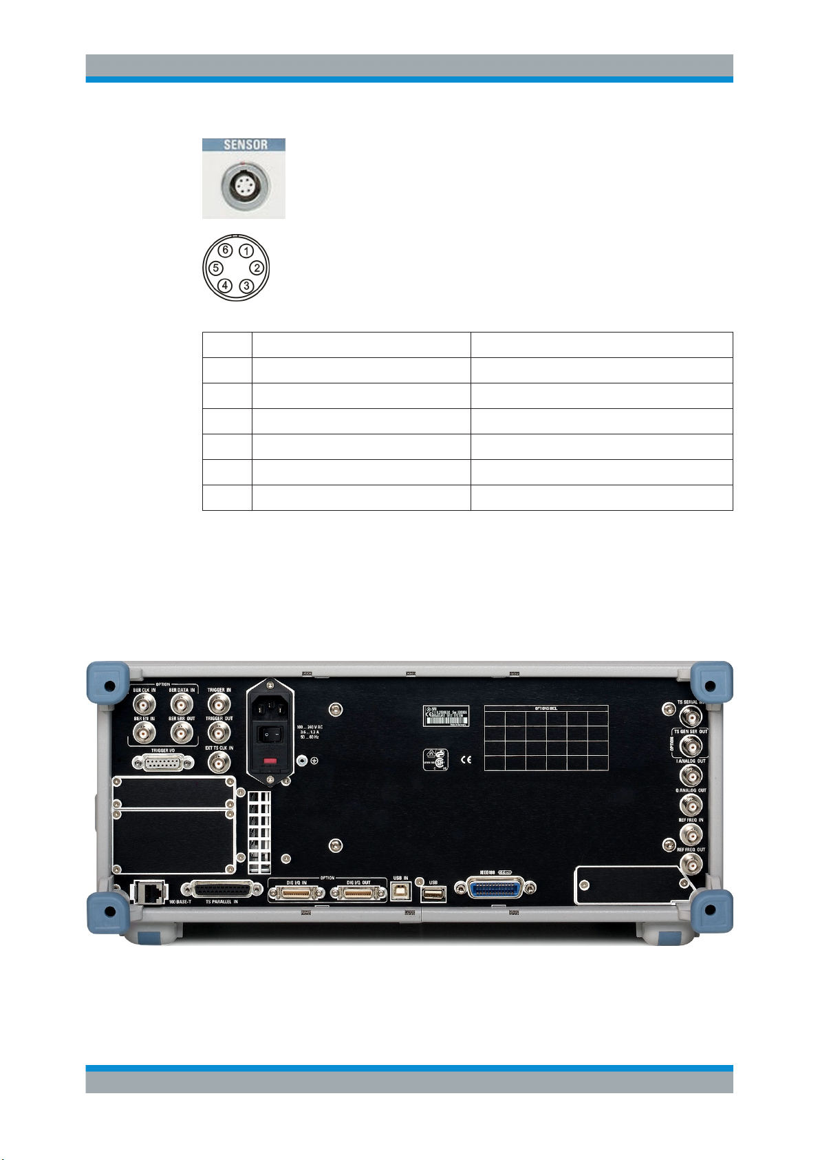
3.1.13 SENSOR
See (13) in Figure 3-1.
ODU mini-snap connector, series B (manufacturer: ODU-Steckverbindersysteme
GmbH). Used to connect a power sensor (R&S NRP-Z21 or R&S NRP-Z51). It allows
independent power measurement and calibration of the RF signal from the R&S SFU.
This connector is USB port 2 of the R&S SFU (but it has been extended to include two
trigger signals).
18Getting Started 2110.2522.62 ─ 18
Page 19
R&S®SFU
Interfaces and Connectors
Rear Panel
Table 3-3: Pin assignment
Pin Abbreviation Signal
1 +5VUSB +5V USB
2 USBD- Data-
3 USBD+ Data+
4 USBGND Ground
5 SENS_TRIG+ Trigger, pos.
6 SENS_TRIG- Trigger, neg.
3.2 Rear Panel
This chapter provides an overview of the controls and connectors on the rear panel.
Each control or connector is briefly described along with a reference to the chapter(s)
containing detailed information about its usage.
19Getting Started 2110.2522.62 ─ 18
Page 20

R&S®SFU
Interfaces and Connectors
Rear Panel
3.2.1 AC Power Supply Connector and Switch
The IEC 320 / EN 60320 AC power supply connector and the AC power switch are
combined (type C14).
A fuse holder is integrated.
The AC power switch is located below the AC power supply connector.
Switch positions:
●
I: Depending on the setting of the On/Standby function key on the front panel, the
R&S SFU is either in standby mode or in operation.
●
O: The entire instrument is disconnected from the AC power supply.
For further information:
●
See Chapter 9.2, "Replacing the Fuses", on page 57
●
See Chapter 4.2, "Connecting to the AC Power Supply", on page 31
●
See Chapter 5, "Switching On or Off the R&S SFU", on page 35
3.2.2 BER Interfaces
These four BNC female connectors are used by the bit error rate tester application
(BER R&S SFU-K60) for the serial bit error rate (BER) measurement.
For further details see user manual or the help system.
20Getting Started 2110.2522.62 ─ 18
Page 21

R&S®SFU
Interfaces and Connectors
Rear Panel
BER CLK IN/BER DATA IN
Inputs for a data stream that has a bit clock associated with it. When there are no
errors, the data sequence is a standardized pseudo-random bit sequence (PRBS). If
there are errors, the BER application compares the received data against the PRBS in
order to detect the errors.
BER EN IN
Input to extract parts of the bit sequence on "BER DATA IN" that are not related to the
PRBS. This can include synchronization and framing bits.
BER ERR OUT
Each time a bit error is detected, a pulse is output. External devices can detect and
process these pulses.
3.2.3 TRIGGER I/O
SUB-D connector (female, 15-pin) for trigger signals. To output a number of distinct
signals that can be processed by external hardware. There are also ground connections and a +5 V voltage (max. 20 mA) that can be used to operate user-specific hardware.
Table 3-4: Pin assignment
Pin Abbreviation Signal
1 TRIGGER I/O 1 Ground
2 TRIGGER I/O 2 Ground
3 TRIGGER I/O 3 user defined
4 TRIGGER I/O 4 user defined
5 TRIGGER I/O 5 user defined
6 TRIGGER I/O 6 user defined
7 TRIGGER I/O 7 user defined
8 TRIGGER I/O 8 user defined
9 TRIGGER I/O 9 user defined
10 TRIGGER I/O 10 user defined
11 TRIGGER I/O 11 user defined
12 TRIGGER I/O 12 user defined
13 TRIGGER I/O 13 Ground
21Getting Started 2110.2522.62 ─ 18
Page 22

R&S®SFU
Interfaces and Connectors
Rear Panel
Pin Abbreviation Signal
14 TRIGGER I/O 14 Ground
15 TRIGGER I/O 15 +5V
3.2.4 TRIGGER IN/TRIGGER OUT/EXT TS CLK IN
TRIGGER IN
BNC connector used by various applications as an input.
TRIGGER OUT
BNC connector used by various applications as an output.
EXT TS CLK IN
BNC connector used to input an external clock signal for the transport data stream.
This input can be selected in the "CODING" menu under "INPUT SIGNAL" / "STUFFING". For further details see the user manual or the help system.
3.2.5 T-DMB/DAB
External ETI input / output (ensemble transport interface) for T-DMB/DAB transmission
standard. The BNC female connectors are associated with the specification ETS
300 799. ETI NI (network independent) and ETI NA 5592 or ETI NA 5376 (network
adaptation) signals are accepted.
For further details see user manual or the help system.
22Getting Started 2110.2522.62 ─ 18
Page 23

R&S®SFU
Interfaces and Connectors
Rear Panel
3.2.6 USER IN/OUT
Application-specific inputs/outputs.
3.2.7 100 BASE-T
The bit rate of the LAN interface (100 Base-T) depends on the R&S SFU serial number:
●
To 100999: 100 Mbit
●
From 101000: 1 Gbit
Used to connect the R&S SFU to a local network for remote control, remote operation,
printouts and data transfer. The assignment of the RJ.45 CAT5 connector supports
twisted pair category 7 UTP/STP cables in a star configuration (UTP stands for
"unshielded twisted pair", and STP for "shielded twisted pair").
Do not connect or disconnect the network cable until the instrument is switched off.
Otherwise, the network connection cannot be reliably detected.
Electromagnetic interference (EMI) can affect the measurement results. To avoid any
impact, use category 7 cables.
For further information:
●
See Chapter 7, "Operating the R&S SFU in a LAN", on page 45
●
See user manual or the help system for remote control using the Ethernet
Table 3-5: Pin assignment
Pin Abbreviation Signal
1 TXD+ Transmit data, positive
2 TXD- Transmit data, negative
23Getting Started 2110.2522.62 ─ 18
Page 24

R&S®SFU
Interfaces and Connectors
Rear Panel
Pin Abbreviation Signal
3 RXD+ Receive data, positive
4, 5 R0 Termination, 75R
6 RXD- Receive data, negative
7, 8 R1 Termination, 75R
3.2.8 TS PARALLEL IN
For details see Chapter 3.1.10, "TS PARALLEL IN", on page 16.
3.2.9 DIG I/Q
Requires the extended I/Q input/output option (R&S SFU-K80). Used to receive and
output digital I/Q signals from (or to) another R&S instrument with the same interface.
For further details see the user manual or the help system.
3.2.9.1 DIG I/Q IN
Digital I/Q input of the R&S SFU.
Table 3-6: Input pin assignment
Pin Name Signal
1 DIG_IQ_CLK2+ Data clock 2 (control signal)
2 GND Ground (control signal)
3 DIG_IQ_IN_D0+ Data bit (LSB), OUT/IN 0 line (I/Q signal)
4 DIG_IQ_IN_D1+ Data bit, OUT/IN 1 line (I/Q signal)
24Getting Started 2110.2522.62 ─ 18
Page 25

R&S®SFU
Interfaces and Connectors
Rear Panel
Pin Name Signal
5 DIG_IQ_IN_D2+ Data bit, OUT/IN 2 line (I/Q signal)
6 DIG_IQ_IN_CLK1+ Data clock 1 (I/Q signal)
7 DIG_IQ_IN_SCLK Serial clock (control signal)
8 +U5V2 +5 V (control signal)
9 DIG_IQ_IN_D3+ Data bit, OUT/IN 3 line (I/Q signal)
10 DIG_IQ_IN_D4+ Data bit, OUT/IN 4 line (I/Q signal)
11 DIG_IQ_IN_D5+ Data bit, OUT/IN 5 line (I/Q signal)
12 DIG_IQ_IN_D6+ Data bit, OUT/IN 6 line (I/Q signal)
13 DIG_IQ_IN_D7+ Data bit (MSB), OUT/IN 7 line (I/Q signal)
14 DIG_IQ_CLK2- Data clock 2 (control signal)
15 DIG_IQ_IN_D0- Data bit (LSB), OUT/IN 0 line (I/Q signal)
16 DIG_IQ_IN_D1- Data bit, OUT/IN 1 line (I/Q signal)
17 DIG_IQ_IN_D2- Data bit, OUT/IN 2 line (I/Q signal)
18 DIG_IQ_IN_CLK1- Data clock 1 (I/Q signal)
19 GND Ground (control signal)
20 DIG_IQ_IN_SDAT Serial data (control signal)
21 DIG_IQ_IN_D3- Data bit, OUT/IN 3 line (I/Q signal)
22 DIG_IQ_IN_D4- Data bit, OUT/IN 4 line (I/Q signal)
23 DIG_IQ_IN_D5- Data bit, OUT/IN 5 line (I/Q signal)
24 DIG_IQ_IN_D6- Data bit, OUT/IN 6 line (I/Q signal)
25 DIG_IQ_IN_D7- Data bit (MSB), OUT/IN 7 line (I/Q signal)
26 GND Ground (control signal)
Line pairs have a name that only differs in the last character. For example, the pins 1
and 14 are a pair.
3.2.9.2 DIG I/Q OUT
Digital I/Q output of the R&S SFU.
25Getting Started 2110.2522.62 ─ 18
Page 26

R&S®SFU
Interfaces and Connectors
Rear Panel
Table 3-7: Output pin assignment
Pin Abbreviation Signal
1 N.C. -
2 GND Ground (control signal)
3 DIG_IQ_OUT_D0+ Data bit (LSB), OUT/IN 0 line (I/Q signal)
4 DIG_IQ_OUT_D1+ Data bit, OUT/IN 1 line (I/Q signal)
5 DIG_IQ_OUT_D2+ Data bit, OUT/IN 2 line (I/Q signal)
6 DIG_IQ_OUT_CLK+ Data clock (I/Q signal)
7 DIG_IQ_OUT_SCLK Serial clock (control signal)
8 N.C. -
9 DIG_IQ_OUT_D3+ Data bit, OUT/IN 3 line (I/Q signal)
10 DIG_IQ_OUT_D4+ Data bit, OUT/IN 4 line (I/Q signal)
11 DIG_IQ_OUT_D5+ Data bit, OUT/IN 5 line (I/Q signal)
12 DIG_IQ_OUT_D6+ Data bit, OUT/IN 6 line (I/Q signal)
13 DIG_IQ_OUT_D7+ Data bit (MSB), OUT/IN 7 line (I/Q signal)
14 N.C. -
15 DIG_IQ_OUT_D0- Data bit (LSB), OUT/IN 0 line (I/Q signal)
16 DIG_IQ_OUT_D1- Data bit, OUT/IN 1 line (I/Q signal)
17 DIG_IQ_OUT_D2- Data bit, OUT/IN 2 line (I/Q signal)
18 DIG_IQ_OUT_CLK- Data clock (I/Q signal)
19 GND Ground (control signal)
20 DIG_IQ_OUT_SDAT Serial data (control signal)
21 DIG_IQ_OUT_D3- Data bit, OUT/IN 3 line (I/Q signal)
22 DIG_IQ_OUT_D4- Data bit, OUT/IN 4 line (I/Q signal)
23 DIG_IQ_OUT_D5- Data bit, OUT/IN 5 line (I/Q signal)
24 DIG_IQ_OUT_D6- Data bit, OUT/IN 6 line (I/Q signal)
25 DIG_IQ_OUT_D7- Data bit (MSB), OUT/IN 7 line (I/Q signal)
26 GND Ground (control signal)
Line pairs have a name that only differs in the last character. For example, the pins 1
and 14 are a pair.
3.2.10 USB IN
Not in use.
26Getting Started 2110.2522.62 ─ 18
Page 27

R&S®SFU
Interfaces and Connectors
Rear Panel
3.2.11 USB Interface
USB interface (universal serial bus) type A (host USB). For details see Chapter 3.1.12,
"USB Interfaces", on page 18.
3.2.12 IEEE 488/IEC 625
IEC bus (IEEE 488) interface for remote control of the R&S SFU. Used to connect a
controller to remote control the R&S SFU. Use a shielded cable for the connection.
Characteristics of the IEC bus (IEEE 488) interface:
●
8 bit parallel data transfer
●
Bidirectional data transfer
●
Three-wire handshake
●
High data transfer rate
●
Up to 15 R&S SFUs can be connected
●
Maximum length of connecting cables 15 m (single connection 2 m)
●
Wired OR operation with parallel connection of several R&S SFUs
For further details see user manual or the help system.
27Getting Started 2110.2522.62 ─ 18
Page 28

R&S®SFU
Interfaces and Connectors
Rear Panel
Table 3-8: Pin assignment
Pin Abbreviation Signal
1 IEC_D0 Data bit 0 (LSB)
2 IEC_D1 Data bit 1
3 IEC_D2 Data bit 2
4 IEC_D3 Data bit 3
5 IEC_EOI End of Identify
6 IEC_DAV Data Valid
7 IEC_NRFD Not Ready for Data
8 IEC_NDAC Not Data Accepted
9 IEC_IFC Interface Clear
10 IEC_SRQ Service Request
11 IEC_ATN Attention
12 GND Ground
13 IEC_D4 Data bit 4
14 IEC_D5 Data bit 5
15 IEC_D6 Data bit 6
16 IEC_D7 Data bit 7
17 IEC_REN Remote Enable
18 GND Ground
19 GND Ground
20 GND Ground
21 GND Ground
22 GND Ground
23 GND Ground
24 GND Ground
3.2.13 TS SERIAL IN
For details see Chapter 3.1.11, "TS SERIAL IN", on page 17.
28Getting Started 2110.2522.62 ─ 18
Page 29

R&S®SFU
Interfaces and Connectors
Rear Panel
3.2.14 TS GEN SER OUT
Requires the TS generator option (R&S SFU-K20). Used to output the serial MPEG2
transport stream and therefore allows you to make external use of the transport stream
generated internally by the R&S SFU. The provided signal is in ASI (asynchronous
serial interface) or SMPTE 310 (society of motion picture and television engineers) format.
3.2.15 I ANALOG OUT/Q ANALOG OUT
BNC connectors. Used to output the analog I and Q signals. Both signals are from the
internal D/A converters. They are also fed to the modulator. These two analog outputs
have separate output drivers.
The outputs can be sent to an external quadrature modulator in order to produce a further modulated signal. These connectors are also used to analyze the baseband signals prior to the modulator.
3.2.16 REF FREQ IN
BNC connector. Used to input the reference frequency.
Reference frequency input.
For further details see user manual or the help system.
3.2.17 REF FREQ OUT
BNC connector. Used to output the reference frequency.
29Getting Started 2110.2522.62 ─ 18
Page 30

R&S®SFU
Interfaces and Connectors
Rear Panel
At the reference frequency output, a signal is always present. When using an internal
reference, the frequency generated by the internal reference oscillator of the R&S SFU
is made available. If an external reference is activated, the signal applied to the reference frequency input is also available here. It is buffered and filtered.
30Getting Started 2110.2522.62 ─ 18
Page 31

R&S®SFU
Connecting the R&S SFU
Connecting to the AC Power Supply
4 Connecting the R&S SFU
This chapter describes how to connect the R&S SFU to the power supply and external
devices.
4.1 Preventing Electromagnetic Interference
To prevent electromagnetic interference, the R&S SFU must be operated with all
shielding covers fitted. Only suitable and shielded signal and control cables may be
used.
RF/ASI/BER/TRIGGER inputs and outputs
In particular cables that are connected to these inputs/outputs can cause EMC problems. Therefore these cables should have at least 80 dB to 1 GHz shielding. This is
usually achieved by means of double-shielded cables.
TS GEN SER OUT
If a cable is attached to this output, it must be provided with a matched load. For
details on the interface see Chapter 3.2.14, "TS GEN SER OUT", on page 29.
USB interfaces
To connect the USB interfaces, only use peripheral equipment that does not cause
limit violations. For details see Chapter 3.1.12, "USB Interfaces", on page 18.
DIG I/Q IN/OUT
If the DIG I/Q IN/OUT is connected by means of a conventional cable, it is possible that
the specifications of limit class B are not longer met. For details on the interface see
Chapter 3.2.9, "DIG I/Q", on page 24.
LAN interface (100 BASE-T)
To connect the LAN interface (100 BASE-T), use a suitable cable. For details see
Chapter 3.2.7, "100 BASE-T", on page 23.
4.2 Connecting to the AC Power Supply
The R&S SFU can be used with different AC power voltages and adapts itself automatically to it. Adjusting the R&S SFU to a particular AC supply voltage is therefore not
required. Refer to the data sheet for the requirements of voltage and frequency.
31Getting Started 2110.2522.62 ─ 18
Page 32

R&S®SFU
Connecting the R&S SFU
Connecting External Devices
Shock hazard
Observe the basic safety instructions at the beginning of this manual, especially the
instructions on electrical safety.
Take care that the AC voltage lies within the limits printed on the AC power connector
of the R&S SFU and listed in the data sheet.
► Connect the R&S SFU to the AC power supply, using the power cable that is sup-
plied. The AC power connector is located on the rear panel of the R&S SFU.
Since the R&S SFU complies with safety class EN61010-1, it should only be connected to a socket with a ground contact.
For further information see Chapter 3.2.1, "AC Power Supply Connector and Switch",
on page 20.
4.3 Connecting External Devices
Using the USB interfaces, you can directly connect USB devices to the R&S SFU. This
number can be increased as necessary by using USB hubs.
Due to the large number of available USB devices, there is almost no limit to the possible expansions. In the following, USB devices that can be useful are listed.
●
Keyboard for entering comments, file names, etc. or for easy access to Windows XP settings. See Chapter 4.3.1, "External Keyboard", on page 33.
●
Mouse for easy operation of Windows dialogs. See Chapter 4.3.2, "Mouse",
on page 34.
●
Memory stick for easy transfer of data to/from a computer (e.g. firmware updates).
See Chapter 4.3.3, "Memory Stick", on page 34.
●
CD–ROM drives for easy installation of firmware applications.
●
Printer for printing out measurement results.
To install a USB device
1. Connect the USB device to the R&S SFU. You can do this during operation
because all USB devices are Plug and Play.
Windows XP automatically searches for a suitable device driver.
2. If Windows XP does not find a suitable driver, it will prompt you to specify a direc-
tory that contains the driver software. If the driver software is on a CD-ROM, connect a USB CD-ROM drive to the R&S SFU before proceeding.
To uninstall a USB device
► Disconnect the USB device from the R&S SFU. You can do this during operation.
32Getting Started 2110.2522.62 ─ 18
Page 33

R&S®SFU
Connecting the R&S SFU
Connecting External Devices
Windows XP immediately detects the change in the hardware configuration and
deactivates the corresponding driver.
4.3.1 External Keyboard
Connect the keyboard to one of the USB interfaces (type A). The default language setting is for a UK keyboard. You can change the language and modify other settings
such as the repetition rate in Windows XP.
Changing Regional and Language Settings
1. Open the "Start" menu by pressing the WINDOWS key on an external keyboard.
2. Select "Control Panel" and then "Keyboard" or "Regional and Language Options".
Table 4-1: Corresponding keys: front panel - external keyboard
Key on front panel Corresponding key on keyboard Function description
Rotary knob: left turn TAB See Chapter 3.1.5, "Rotary Knob", on page 14
Rotary knob: right turn SHIFT+TAB "
Rotary knob: press ENTER "
Cursor keys LEFTARROW, RIGHTARROW, UPAR-
ROW, DNARROW
Alphanumeric keys 1 to 9 1...9 / a...z See Chapter 3.1.4, "Keypad", on page 14
0 0
SPACEBAR
See Chapter 3.1.6, "Cursor Keys", on page 15
"
.
*...#
+
-
A↔a
CLR DEL "
ESC ESC "
BACKSPACE BACKSPACE "
ENTER ENTER "
MHZ/DBµV ALT+F10 "
KHZ/DBM ALT+F11 "
HZ/DB ALT+F12 "
Softkeys CTRL+"1...8" See Chapter 3.1.3, "Softkeys", on page 14
PRESET F4 See Chapter 3.1.2, "Hardkeys", on page 13
LOCAL F3 "
.
*...#
SHIFT+"+"
-
Capital letters: SHIFT+"a...z"
"
"
33Getting Started 2110.2522.62 ─ 18
Page 34

R&S®SFU
Key on front panel Corresponding key on keyboard Function description
ASSIGN F2 "
HELP F1 "
FILE F5 "
SETUP F6 "
HOME F8 "
APPL F9 "
STATUS F7 "
Connecting the R&S SFU
Connecting External Devices
4.3.2 Mouse
You can change settings such as the speed of the mouse cursor in Windows XP.
Changing Mouse Settings
1. Open the "Start" menu by pressing the WINDOWS key on an external keyboard.
2. Select "Control Panel" and then "Mouse".
4.3.3 Memory Stick
The R&S SFU has a disk drive. You can exchange data by using a memory stick which
you plug into one of the USB interfaces. The memory stick is automatically assigned a
free drive letter and you can use Windows Explorer to transfer data.
4.3.4 External Monitor
The R&S SFU does not have a connector for connecting an external monitor with an
analog interface. However, you can display the screen on external monitors by using
remote operation on an external computer.
For details on how to activate the power save mode see Chapter 5.2, "Switching On
the R&S SFU", on page 36.
For details on remote operation see the user manual or the help system.
34Getting Started 2110.2522.62 ─ 18
Page 35
R&S®SFU
Switching On or Off the R&S SFU
Instrument States
5 Switching On or Off the R&S SFU
Shock hazard
Observe the basic safety instructions at the beginning of this manual, especially the
instructions on electrical safety.
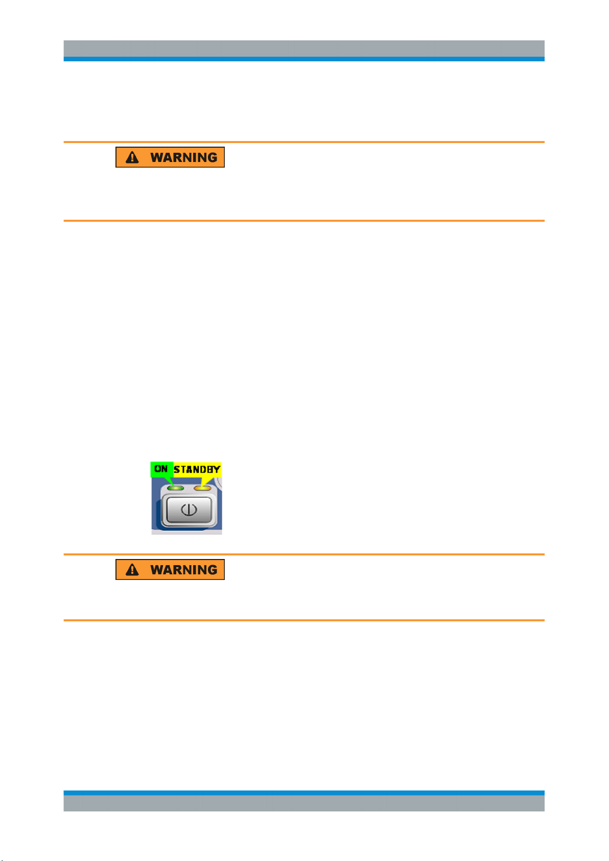
5.1 Instrument States
The following states are possible:
●
Off
The AC power switch on the back of the R&S SFU is switched off (see Chap-
ter 3.2.1, "AC Power Supply Connector and Switch", on page 20).
●
Ready
The R&S SFU is ready for operation.
The green LED (left LED) on the on/standby key is illuminated (see also Chap-
ter 3.1.1, "On/Standby Key", on page 13).
●
Standby
The power supply has the operating voltage supplied to it and the crystal oven is
maintained at its operating temperature.
The yellow LED (right LED) on the on/standby key is illuminated.
Shock hazard
In standby mode, the R&S SFU is still power-supplied.
35Getting Started 2110.2522.62 ─ 18
Page 36

R&S®SFU
Switching On or Off the R&S SFU
Switching On the R&S SFU
5.2 Switching On the R&S SFU
Risk of instrument damage
Before switching on the R&S SFU, make sure that the following conditions are met:
●
The R&S SFU is set up as described in Chapter 2, "Setting Up the R&S SFU",
on page 9.
●
Signal levels at the input connectors are all within the specified ranges.
●
Signal outputs are correctly connected and are not overloaded. In particular, do not
exceed the maximum permissible reverse power allowed at the RF output.
The values are specified in the data sheet. Failure to meet these conditions may cause
damage to the R&S SFU or other devices in the test setup.
To switch on the R&S SFU
1. Make sure that the R&S SFU is connected to a power supply (for details see Chap-
ter 4.2, "Connecting to the AC Power Supply", on page 31).
2. Press the AC power switch on the rear panel into I position (for details see Chap-
ter 3.2.1, "AC Power Supply Connector and Switch", on page 20).
3. Press the on/standby key on the front panel.
The R&S SFU starts booting:
● The installed BIOS version and some of the computer features are displayed
on the screen for a few seconds.
● The Windows XP Embedded operating system is booted, followed by the
R&S SFU firmware.
● A self-test is performed.
After booting is completed, the main screen of the R&S SFU is displayed, and the
R&S SFU is ready for operation.
If the external monitor remains dark, proceed as described in Chapter 4.3.4, "Exter-
nal Monitor", on page 34.
(Ready state, see Chapter 5.1, "Instrument States", on page 35.)
The configuration settings that were active before the R&S SFU was last switched
off are automatically restored.
Use the "FILE" menu to load another instrument setting. For details see the user
manual or the help system.
Activating the power save mode
Power save mode is not set by default for the R&S SFU.
If you do not need the display, you can switch off the monitor in Windows XP under
"Start" – "Control Panel" – "Power Options after a particular time".
36Getting Started 2110.2522.62 ─ 18
Page 37

R&S®SFU
Switching On or Off the R&S SFU
Checking the Provided Options
5.3 Switching Off the R&S SFU
Risk of losing data
If you switch off the running R&S SFU using the rear panel switch or by disconnecting
the power cord before shutting it down, the R&S SFU loses its current settings. Furthermore, program data may be lost.
Always shut down the R&S SFU first.
To switch off the R&S SFU
1. Press the on/standby key on the front panel.
The R&S SFU saves the current settings to the hard disk and shuts down the Windows operating system. During this process, the "Ending Program...Please wait"
message may be displayed.
The power supply is switched over to standby and the yellow LED on the on/
standby key is illuminated.
2. If you want to completely disconnect the broadcast test system from the AC power
line, set the AC switch on the rear panel to the O position, or disconnect the
R&S SFU from the AC power supply.
All LEDs on the on/standby key should go out.
You can leave the AC power switch switched on permanently. You only need to switch
off the R&S SFU if you want to completely disconnect it from the AC power line.
5.4 Checking the Provided Options
The R&S SFU may be equipped with options. In order to check whether the installed
options correspond to the options indicated on the delivery note, proceed as follows.
1. Press the SETUP key.
2. In the tree, select "INFO HARDWARE" to display a list showing the currently installed hardware.
3. Check the availability of the hardware options as indicated in the delivery note.
4. In the tree, select "SOFTWARE OPTIONS" and then "ACTIVE OPTIONS" to display a short tabular overview of the enabled software options.
5. Check the availability of the software options as indicated in the delivery note.
37Getting Started 2110.2522.62 ─ 18
Page 38

R&S®SFU
Switching On or Off the R&S SFU
Turn-On Tests
For further details see the user manual or the help system.
For an overview of the all options available for the R&S SFU refer to the Rohde &
Schwarz Homepage.
5.5 Turn-On Tests
If an error is detected, an error indication is displayed in the error/warnings line along
with a brief description of the error.
► To obtain more information about the error, press the "ERROR/WARNING
DETAILS" softkey.
A description of the error(s) or warning(s) is displayed.
For further details see the user manual or the help system.
Besides automatic monitoring of instrument functions, the R&S SFU also offers the following way of ensuring proper operation.
System adjustment
Use the SETUP menu to carry out an internal adjustment. This is a way of obtaining
the best possible level accuracy, for example.
1. Press the SETUP key.
2. In the tree, select "ADJUSTMENT".
For further details see the user manual or the help system.
38Getting Started 2110.2522.62 ─ 18
Page 39

R&S®SFU
6 Sample Application
The following example involves the following main steps:
●
Feed an MPEG2 transport stream to the R&S SFU using the serial interface (TS
SERIAL IN ASI, see Chapter 3.1.11, "TS SERIAL IN", on page 17) on the front
panel.
●
This MPEG2 transport stream undergoes channel encoding and modulation for
transmission in compliance with the DVB-C specification. To achieve this, perform
the following step-by-step instructions. The involved settings are summed up in
Table 6-1.
●
The result is output as an RF signal on the RF output.
Table 6-1: Involved settings
Parameter Value
Center frequency 330 MHz
Level -20.0 dBm
Sample Application
Transmission standard DVB-C
Constellation 64 QAM
Symbol rate 6.9 MS/s
Roll off 0.15
An explanation of the graphical user interface and information on how to select items,
open lists and enter parameters are provided in the user manual or the help system.
Selecting the transmitter application (TX)
1. Press the APPL key.
2. Select the TX application (DVB-C transmission is a transmitter application).
3. Press the ENTER key.
The TX application is displayed.
Setting the output frequency
1. In the tree, select the "FREQUENCY" menu.
2. Press the ENTER key.
The tree is expanded and the "FREQUENCY" submenu is displayed.
39Getting Started 2110.2522.62 ─ 18
Page 40

R&S®SFU
Sample Application
3. In the tree, select the "FREQUENCY" submenu.
4. Press the ENTER key.
The focus is set on the work view.
5. Set a frequency of 330 MHz.
a) Select the "FREQUENCY" field.
b) Enter 330.
c) Press the MHz/dBµV key.
The entered frequency is displayed in the info area.
Setting the output level
1. In the tree, select the "LEVEL" menu.
2. Press the ENTER key.
The tree is expanded and the "LEVEL" submenu is displayed.
40Getting Started 2110.2522.62 ─ 18
Page 41

R&S®SFU
Sample Application
3. In the tree, select the "LEVEL" submenu.
4. Press the ENTER key.
The focus is set on the work view.
5. Set a level of -20 dBm.
a) Select the "LEVEL" field.
b) Enter -20.
c) Press the kHz/dBm key.
d) If you want to enter the level in a different unit, change the unit in the "LEVEL"
menu, under "SETTINGS" / "LEVEL UNIT" first (see user manual or help system).
The entered level is displayed in the info area.
Setting the modulation parameters and selecting the transmission standard
1. In the tree, select the "MODULATION" menu.
2. Press the ENTER key.
The tree is expanded and the "MODULATION" submenu is displayed.
41Getting Started 2110.2522.62 ─ 18
Page 42

R&S®SFU
Sample Application
3. In the tree, select the "MODULATION" submenu.
4. Press the ENTER key.
The focus is set on the work view.
5. Activate the modulation.
a) Select the "MODULATION" field.
b) Press the ENTER key to display the list.
c) Select "ON".
d) Press the ENTER key to confirm the selection.
6. Select the "DTV" signal source.
a) Select the "SIGNAL SOURCE" field.
b) Press the ENTER key to display the list.
c) Select "DTV".
d) Press the ENTER key to confirm the selection.
7. Select the "DVB-C" transmission standard.
a) Select the "TRANSMISSION STANDARD" field.
b) Press the ENTER key to display the list.
c) Select "DVB-C".
d) Press the ENTER key to confirm the selection.
The selected standard is displayed in the info area.
The I/Q modulation is switched on, the internal coder is selected as the signal
source, and the DVB-C transmission standard is set.
42Getting Started 2110.2522.62 ─ 18
Page 43

R&S®SFU
Sample Application
Selecting the transport stream input and setting the DVB-C transmission parameters
1. In the tree, select the "DIGITAL TV" menu.
2. Press the ENTER key.
The tree is expanded and the "DIGITAL TV" submenu is displayed.
(See Figure 6-1.)
3. In the tree, select the "INPUT SIGNAL" submenu.
4. Press the ENTER key.
The focus is set on the work view.
5. Select the "EXTERNAL" signal source.
a) Select the "SOURCE" field.
b) Press the ENTER key to display the list.
c) Select "EXTERNAL".
d) Press the ENTER key to confirm the selection.
6. Select the "ASI FRONT" input.
a) Select the "INPUT" field.
b) Press the ENTER key to display the list.
c) Select "ASI FRONT".
d) Press the ENTER key to confirm the selection.
7. Make sure that the "STUFFING" field in the work view is set to "ON".
This ensures that the incoming transport stream will be adapted to the proper data
rate of the coder. The data rate of the coder will depend on the transmission
parameters. The data stream is padded with null packets to allow adaptation to the
transmission parameters.
a) Select the "STUFFING" field.
b) Press the ENTER key to display the list.
c) Select "ON".
d) Press the ENTER key to confirm the selection.
8. Select "BACK" and press the ENTER key.
The focus is set to the tree.
9. In the tree, select the "CODING" submenu.
43Getting Started 2110.2522.62 ─ 18
Page 44

R&S®SFU
Sample Application
Figure 6-1: DIGITAL TV menu
10. Press the ENTER key.
The focus is set on the work view.
11. Select a symbol rate of 6.9 .MS/s.
a) Select the "SYMBOL RATE" field.
b) Enter 6.9.
c) If the units field to the right shows "MS/s", press the ENTER key.
d) If the units field indicates another unit, select this field. Press the ENTER key,
and select the "MS/s" unit. Press the ENTER key twice to confirm the unit and
the symbol rate.
The selected symbol rate is displayed in the info area.
12. Select the "64 QAM" constellation.
a) Select the "CONSTELLATION" field.
b) Press the ENTER key to display the list.
c) Select "64 QAM".
d) Press the ENTER key to confirm the selection.
The selected constellation is displayed in the info area.
44Getting Started 2110.2522.62 ─ 18
Page 45

R&S®SFU
Operating the R&S SFU in a LAN
Connecting the R&S SFU to the Network
7 Operating the R&S SFU in a LAN
The R&S SFU is equipped with a network interface and can be connected to an Ethernet LAN (local area network). The network card operates with 100 MBit Ethernet IEEE
802.3u. The TCP/IP network protocol and the associated network services are precon-
figured.
To be able to exchange data within a local area network (LAN), every computer or
instrument that is connected must have a unique IP address or a unique computer
name. Access between different users is managed with access authorizations.
Provided the appropriate rights have been assigned and the Window XP firewall configuration is adapted accordingly, the interface can be used e.g. for transferring data,
printing on network printers, operating the R&S SFU from a remote computer.
To use network resources, access must be granted. To share files on the R&S SFU
with other network users, access to instrument resources, e.g. the hard drives, must
also be granted. All these administration tasks are normally performed by a network
administrator using the Windows XP Start menu (for details refer to the Windows XP
help system). Contact your network administrator for access authorizations.
User name and password of the R&S SFU are factory-set. The user name is used for
auto login, access authorization and remote operation.
For further information:
●
See Chapter 8.1.1, "Login", on page 48
●
See Chapter 3.2.7, "100 BASE-T", on page 23
●
See the user manual or help system for details on remote operation.
7.1 Connecting the R&S SFU to the Network
Risk of network failure/virus infection
Before connecting the R&S SFU to the network or configuring the network, do the following:
●
Consult your network administrator.
●
If your network does not support DHCP or if you choose to disable dynamic TCP/IP
configuration, you must assign valid address information before connecting the
R&S SFU to the LAN.
Errors may affect the entire network.
Efficient virus protection is a prerequisite for secure operation in the network. Never
connect the R&S SFU to a network without proper protection against a virus infection,
as doing so may cause damage to the instrument software.
45Getting Started 2110.2522.62 ─ 18
Page 46

R&S®SFU
Operating the R&S SFU in a LAN
Configuring the Network Card
To connect the R&S SFU to the network
1. Fulfill all prerequisites mentioned above.
2. Make sure that the R&S SFU is switched off. This is the only way to ensure that the
network connection is reliably detected and any disruptions during the operation of
the R&S SFU are avoided.
3. Connect the R&S SFU to the network using a CAT-5 RJ-45 cable.
4. Switch on the R&S SFU.
To disconnect the R&S SFU from the network
1. Make sure that the R&S SFU is switched off.
2. Disconnect the R&S SFU from the network.
7.2 Establishing a Point-to-Point Connection
To set up a single network (a LAN connection between an R&S SFU and a single computer without integration into a larger network), an IP address needs to be assigned to
the R&S SFU and the computer. The IP addresses 192.168.xxx.yyy are available for
use here. xxx and yyy can assume values of 1 to 254, and the value for the subnet
mask is 255.255.255.0.
► Connect the R&S SFU and the computer with a standard RJ-45 cross-over cable.
7.3 Configuring the Network Card
Under Windows XP, network card drivers do not need to be installed separately. If the
R&S SFU is connected to the LAN, Windows XP automatically detects the network
connection and activates the required drivers.
The configuration tasks depend on whether your network has a DHCP server or not. If
necessary, ask your network administrator.
Networks with DHCP Server
The R&S SFU is preconfigured for networks using the dynamic host configuration protocol (DHCP). In such networks, the instrument is automatically assigned a free IP
address. Identification in the network is based on the use of a unique computer name.
Every instrument is assigned an individual computer name at the factory. It is displayed
as part of the window title of the application.
If necessary, you can change the computer name using the firmware or the Windows XP Start menu (for details refer to the Windows XP help system).
46Getting Started 2110.2522.62 ─ 18
Page 47

R&S®SFU
Operating the R&S SFU in a LAN
Firewall Settings
Querying the computer name using the firmware
1. If the R&S SFU has a default computer name, the computer name is displayed as
part of the window title of the application.
2. If no default computer name is displayed, do the following.
a) Press the SETUP key.
b) In the tree, select "COMMUNICATION".
c) Read out the computer name from the "FULL COMPUTER NAME" field.
Networks without DHCP Server
In networks that assign fixed IP addresses, the network administrator usually configures the network card. Contact your network administrator. The IP address is set using
the firmware or the Windows XP Start menu (for details refer to the Windows XP help
system).
Entering the IP address using the firmware
1. Press the SETUP key.
2. In the tree, select "COMMUNICATION".
3. Enter the IP address in the "TCP/IP ADDRESS" field.
7.4 Firewall Settings
By default, the Windows Firewall is activated to protect the R&S SFU from an attack of
hostile users and programs. The Windows Firewall suppresses all network communication which is not initialized by the R&S SFU itself or which is not defined as an
exception.
To enable data transfer or to allow access to the R&S SFU, define exceptions using
the Windows XP Start menu. For details refer to the Windows XP help system or contact your network administrator for support.
47Getting Started 2110.2522.62 ─ 18
Page 48
R&S®SFU
8 Installed Software
The firmware and the operating system are already installed on the R&S SFU.
For further information:
●
Performing a firmware update: see the release notes.
●
Installing software options: see the user manual or the help system.
Installed Software
Operating System
8.1 Operating System
The R&S SFU is equipped with the Windows XP Embedded operating system. When
the R&S SFU is delivered, the operating system is configured for optimum operation.
Changes to the system settings are required only if you install peripherals such as a
keyboard and printer or if you configure the network and the settings do not conform to
the default settings.
Risk of causing instrument unusability
To prevent malfunctions and to avoid instrument repair, only install service packs
approved by Rohde & Schwarz.
In particular, do not use service packs for Windows XP Home Edition or Professional
Edition.
8.1.1 Login
Windows XP requires that you identify yourself by entering a user name and password
in a login window. The R&S SFU provides a factory–installed auto login function, i.e.
login is carried out automatically in the background. The ID used for auto login has
administrator rights.
As user name and password, instrument are factory-set.
If the R&S SFU is connected to a network and if the user name and the password are
identical under Windows XP and on the network, you log on to operating system and
the network at the same time.
48Getting Started 2110.2522.62 ─ 18
Page 49

R&S®SFU
Installed Software
Windows XP Recovery and Backup Partition
8.1.2 Windows XP Start Menu
The Windows XP Start menu provides access to the Windows XP functionality and
installed programs. Under "Control Panel", the system settings are grouped. For details
refer to the Windows XP help system.
To access to the operating system, connect an external keyboard. If you want more
convenient access to Windows XP, connect a mouse. To change to the user interface
of the R&S SFU, in the taskbar, double-click the R&S SFU entry.
For details on connecting external devices see Chapter 4.3, "Connecting External
Devices", on page 32.
8.2 Additional Software
Risk of causing instrument unusability
The instrument is equipped with the Windows XP operating system. Additional software can therefore be installed on the instrument. The use and installation of additional
software may impair instrument function. Thus, run only programs that Rohde &
Schwarz has tested for compatibility with the instrument software.
The drivers and programs used on the instrument under Windows XP have been adapted to the instrument. Existing instrument software must always be modified using only
update software released by Rohde & Schwarz.
8.3 Windows XP Recovery and Backup Partition
The R&S SFU provides a backup and recovery partition. A backup of the factory system partition (C:\) is stored per default and can be recovered in case of a system
crash.
In addition, backups of up to 5 firmware versions can be stored on this partition. For
example, it is possible to backup the current system partition prior to a firmware update
or to provide different system configurations for different environments. When recovered, the system partition (C:/) is deleted, formatted and written newly. The data partition (D:\) is not affected.
8.3.1 Windows XP Embedded Recovery and Backup Partition Dialog
To display the Windows XP Embedded Recovery and Backup Partition dialog
1. Connect a keyboard and a mouse to the USB interfaces.
49Getting Started 2110.2522.62 ─ 18
Page 50

R&S®SFU
Installed Software
Windows XP Recovery and Backup Partition
2. Switch the R&S SFU off and on again.
The boot screen is displayed with the default selection "Firmware". If you do not
perform step step 3 within 4 seconds, the dialog vanishes and the booting process
continues.
3. Select "Backup/Recovery" and press ENTER.
The "Windows XP Recovery and Backup Embedded Partition" dialog is displayed.
It shows the available selections for the recovery and backup partition.
50Getting Started 2110.2522.62 ─ 18
Page 51

R&S®SFU
Installed Software
Windows XP Recovery and Backup Partition
Figure 8-1: Windows XP Recovery and Backup Embedded Partition dialog
To continue see one of the following chapters:
●
The Chapter 8.3.1.1, "Backing Up Current System Partition", on page 51
●
The Chapter 8.3.1.2, "Recovering the Selected Version of System Partition",
on page 52
●
The Chapter 8.3.1.3, "Recovering the Factory Default", on page 53
●
The Chapter 8.3.1.4, "Deleting Backups", on page 54
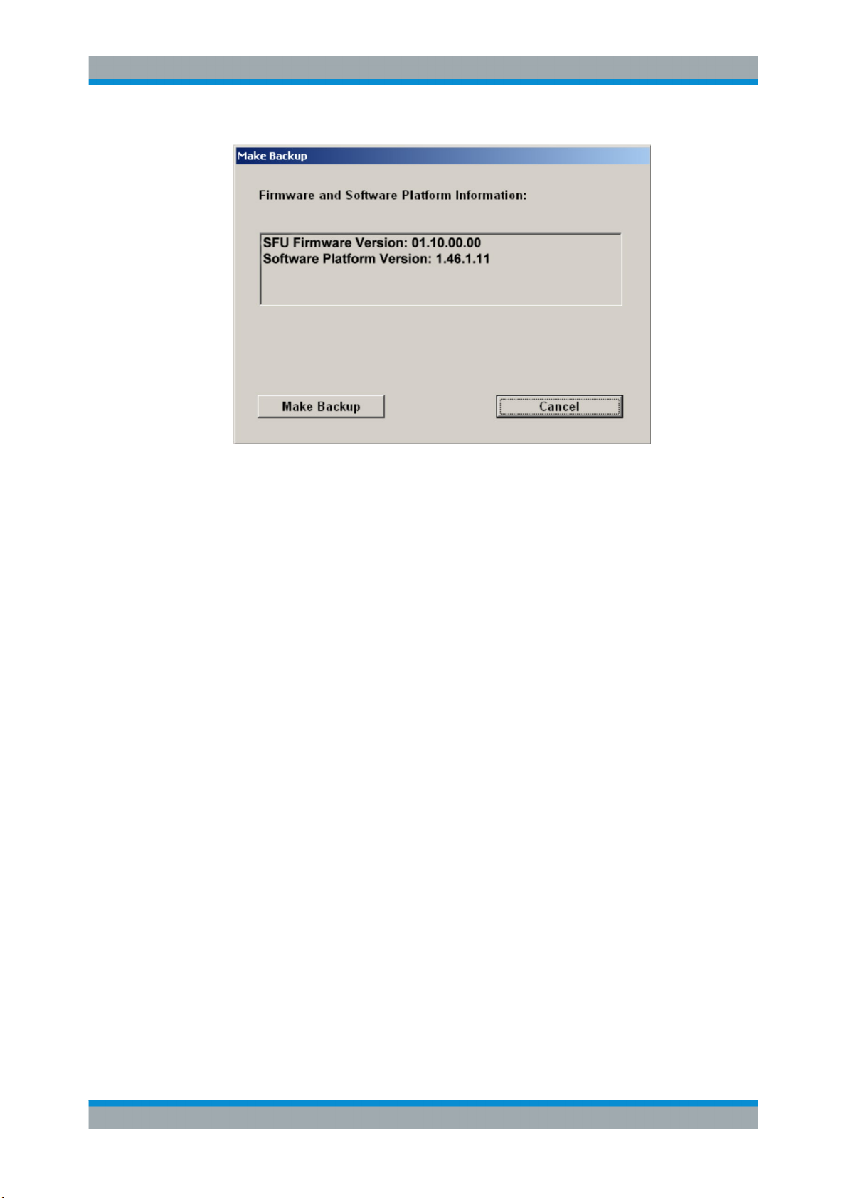
8.3.1.1 Backing Up Current System Partition
1. In the "Windows XP Embedded Recovery and Backup Partition" dialog (see "To
display the Windows XP Embedded Recovery and Backup Partition dialog"
on page 49), click "Make Backup".
The "Make Backup" dialog is displayed. It shows the current versions of the firmware and the software platform.
51Getting Started 2110.2522.62 ─ 18
Page 52
R&S®SFU
Installed Software
Windows XP Recovery and Backup Partition
2. Click "Make Backup".
After the backup, the "Windows XP Embedded Recovery and Backup Partition"
dialog is displayed again.
3. Click "Exit and Shutdown".
8.3.1.2 Recovering the Selected Version of System Partition
1. In the "Windows XP Embedded Recovery and Backup Partition" dialog (see "To
display the Windows XP Embedded Recovery and Backup Partition dialog"
on page 49), click "Restore Backup" to recover a selected version of the system
partition.
The "Restore Backup" dialog is displayed. It shows the versions of the firmware
and the software platform of the backup displayed under "Select Backup".
52Getting Started 2110.2522.62 ─ 18
Page 53

R&S®SFU
Installed Software
Windows XP Recovery and Backup Partition
2. Under "Select Backup", select the backup to be restored.
3. Click "Restore" and follow the instructions.
The script which is performed during recovery is displayed.
After the recovery, the R&S SFU is shut down and switched off.
8.3.1.3 Recovering the Factory Default
1. In the "Windows XP Embedded Recovery and Backup Partition" dialog (see "To
display the Windows XP Embedded Recovery and Backup Partition dialog"
on page 49), click "Factory Default" to recover the factory version of the system
partition.
The "Factory Default" dialog is displayed. It shows the versions of the firmware and
the software platform on delivery.
53Getting Started 2110.2522.62 ─ 18
Page 54

R&S®SFU
Installed Software
Windows XP Recovery and Backup Partition
2. Click "Recover now" and follow the instructions.
The script which is performed during recovery is displayed. After the recovery, the
R&S SFU is shut down and switched off.
8.3.1.4 Deleting Backups
On the recovery partition, you can store up to five backups in addition to the factory
default. To provide space for new backups, you may need to remove older backups.
The factory default cannot be deleted.
1. In the "Windows XP Embedded Recovery and Backup Partition" dialog (see "To
display the Windows XP Embedded Recovery and Backup Partition dialog"
on page 49), click "Remove Backup" to delete a selected backup.
The "Remove Backup" dialog is displayed. It shows the versions of the firmware
and the software platform of the selected backup.
54Getting Started 2110.2522.62 ─ 18
Page 55

R&S®SFU
Installed Software
Windows XP Recovery and Backup Partition
2. Under "Select Backup", select the backup to be deleted.
3. Click "Remove".
After the deletion, the R&S SFU returns to the "Remove Backup" dialog as long as
backups are still available. If the last backup is deleted, the "Windows XP Embedded Recovery and Backup Partition" dialog is displayed again.
4. Click "Cancel" to return the "Windows XP Embedded Recovery and Backup Partition" dialog.
5. Click "Exit and Shutdown".
55Getting Started 2110.2522.62 ─ 18
Page 56

R&S®SFU
Maintenance
Cleaning the Instrument
9 Maintenance
The R&S SFU does not need a periodic maintenance unless it is operated in dusty
areas.
Risk of instrument damage
If the R&S SFU is operated in dusty areas, the fans may become obstructed by dust or
other particles in the process of time. Make sure to check and, if necessary, clean the
fans regularly to ensure they operate properly at all times. If the R&S SFU is run with
obstructed fans for a longer period, it may become overheated which may cause damage.
Clean the outside of the instrument when necessary and check the rated data from
time to time.
If any problem arises, contact one of our customer support centers. The addresses of
our customer support centers are provided at the beginning of this manual.
9.1 Cleaning the Instrument
Shock hazard
Before cleaning the R&S SFU, make sure that the R&S SFU is switched off and disconnected from all power supplies.
1. Clean the outside of the R&S SFU using a soft, lint-free dust cloth.
2. Make sure that vents are not obstructed.
Instrument damage caused by cleaning agents
Cleaning agents contain substances that may damage the R&S SFU, e.g. cleaning
agents that contain a solvent may damage the front panel labeling or plastic parts.
Never use cleaning agents such as solvents (thinners, acetone, etc), acids, bases, or
other substances.
56Getting Started 2110.2522.62 ─ 18
Page 57

R&S®SFU
Maintenance
Storing the Instrument
9.2 Replacing the Fuses
The R&S SFU is protected by two fuses (F1/F2: IEC127-T4.0H/250 V) located on the
rear panel next to the AC power switch.
Shock hazard
Before replacing a fuse, make sure that the R&S SFU is switched off and disconnected
from all power supplies.
Always use fuses supplied by Rohde & Schwarz as spare parts, or fuses of the same
type and rating.
To replace the fuses
1. Open the lid of the AC power connector.
2. Lift the fuse holder out of its slot.
3. Exchange the two fuses.
4. Put the fuse holder back in its slot and close the lid.
9.3 Storing the Instrument
The storage temperature range of the R&S SFU is given in the data sheet. If the
R&S SFU is to be stored for a longer period of time, it must be protected against dust.
Repack the R&S SFU as it was originally packed when transporting or shipping. The
two protective foam plastic parts prevent the control elements and connectors from
being damaged. The antistatic packing foil avoids any undesired electrostatic charging
to occur.
If you do not use the original packaging, provide for sufficient padding to prevent the
R&S SFU from slipping inside the package. Wrap antistatic packing foil around the
R&S SFU to protect it from electrostatic charging.
57Getting Started 2110.2522.62 ─ 18
Page 58

R&S®SFU
Index
Index
Symbols
100 BASE-T connector ..................................................... 23
A
AC power supply
connecting to .............................................................. 31
AC power supply connector .............................................. 20
AC power switch ............................................................... 20
Administrator ID ................................................................ 48
APPL hardkey ................................................................... 13
ASSIGN hardkey ............................................................... 13
B
Backing up system partition ........................................ 49, 51
Bench operation ................................................................ 10
BER connector .................................................................. 20
C
Checking
accessories ................................................................. 10
provided options ......................................................... 37
Cleaning the instrument .................................................... 56
Connecting
external devices .......................................................... 32
power supply ............................................................... 31
Connector .......................................................................... 23
100 BASE-T ................................................................ 23
AC power supply ......................................................... 20
BER ............................................................................ 20
DIG I/Q IN ................................................................... 24
DIG I/Q OUT ............................................................... 25
EXT TS CLK IN ........................................................... 22
I ANALOG OUT .......................................................... 29
I/Q IN .......................................................................... 15
IEEE 488/IEC 625 ....................................................... 27
Q ANALOG OUT ........................................................ 29
REF FREQ IN ............................................................. 29
REF FREQ OUT ......................................................... 29
RF OUT ...................................................................... 16
SENSOR ..................................................................... 18
T-DMB/DAB ................................................................ 22
TRIGGER I/O .............................................................. 21
TRIGGER IN ............................................................... 22
TRIGGER OUT ........................................................... 22
TS GEN SER OUT ..................................................... 29
TS PARALLEL IN ................................................. 16, 24
TS SERIAL IN ....................................................... 17, 28
USB ...................................................................... 18, 27
USB IN ........................................................................ 26
USER IN/OUT ............................................................. 23
Conventions ........................................................................ 8
Cursor keys ....................................................................... 15
D
Deleting system partition backups .................................... 54
DIG I/Q IN connector ......................................................... 24
DIG I/Q OUT connector ..................................................... 25
Display .............................................................................. 15
DNARROW key ................................................................. 15
Documentation overview ..................................................... 7
E
Electromagnetic interference ............................................ 31
preventing ................................................................... 31
EMC precautions ............................................................... 31
EXT TS CLK IN connector ................................................ 22
External devices ................................................................ 32
External keyboard ............................................................. 33
F
FILE hardkey ..................................................................... 13
Firewall settings ................................................................ 47
Firmware
options ........................................................................ 37
update ......................................................................... 48
Front panel ........................................................................ 12
Fuse
replacing ..................................................................... 57
G
Getting started manual ........................................................ 7
H
Hardkey
APPL ........................................................................... 13
ASSIGN ...................................................................... 13
FILE ............................................................................ 13
HELP .......................................................................... 13
HOME ......................................................................... 13
LOCAL ........................................................................ 13
PRESET ..................................................................... 13
SETUP ........................................................................ 13
STATUS ...................................................................... 13
Help ..................................................................................... 8
HELP hardkey ................................................................... 13
HOME hardkey .................................................................. 13
I
I ANALOG OUT connector ................................................ 29
I/Q IN connector ................................................................ 15
IEEE 488/IEC 625 connector ............................................ 27
IP address
changing ..................................................................... 46
K
Key
DNARROW ................................................................. 15
LEFTARROW ............................................................. 15
on/standby .................................................................. 13
RIGHTARROW ........................................................... 15
see also "Hardkey" ...................................................... 15
UPARROW ................................................................. 15
Keypad .............................................................................. 14
L
LAN connector .................................................................. 23
58Getting Started 2110.2522.62 ─ 18
Page 59

R&S®SFU
Index
LEFTARROW key ............................................................. 15
Local area network (LAN) ........................................... 23, 45
LOCAL hardkey ................................................................. 13
Login
Windows XP ............................................................... 48
M
Maintenance ...................................................................... 56
Manual
getting started ............................................................... 7
user manual .................................................................. 7
Memory stick ..................................................................... 34
Mouse ............................................................................... 34
N
Network
configuring card .......................................................... 46
connecting to .............................................................. 45
disconnecting from ...................................................... 45
O
On/standby key ................................................................. 13
Operating system .............................................................. 48
Options
checking ...................................................................... 37
firmware ...................................................................... 37
P
Packing the instrument ...................................................... 57
Password
Windows XP ............................................................... 48
Power supply
connecting to .............................................................. 31
PRESET hardkey .............................................................. 13
Provided options
checking ...................................................................... 37
Putting up the instrument .................................................. 10
Q
Q ANALOG OUT connector .............................................. 29
R
Rack mounting .................................................................. 11
Ready state ....................................................................... 35
Rear panel ......................................................................... 19
Recovering system partition .............................................. 49
factory default ............................................................. 53
selected version .......................................................... 52
Recovery/backup partition dialog ...................................... 49
REF FREQ IN connector ................................................... 29
REF FREQ OUT connector ............................................... 29
Replacing fuses ................................................................. 57
RF OUT connector ............................................................ 16
RIGHTARROW key ........................................................... 15
Rotary knob ....................................................................... 14
Softkeys ............................................................................ 14
Software
installing ...................................................................... 49
Software options
installing ...................................................................... 48
Standby state .................................................................... 35
Start menu ......................................................................... 49
States ................................................................................ 35
STATUS hardkey .............................................................. 13
Storing the instrument ....................................................... 57
Switching off the instrument .............................................. 37
Switching on the instrument .............................................. 36
T
T-DMB/DAB connector ...................................................... 22
TCP/IP protocol
configuring .................................................................. 46
TRIGGER I/O connector ................................................... 21
TRIGGER IN connector .................................................... 22
TRIGGER OUT connector ................................................ 22
TS GEN SER OUT connector ........................................... 29
TS PARALLEL IN connector ....................................... 16, 24
TS SERIAL IN connector ............................................ 17, 28
U
Unpacking the cardboard box ............................................. 9
UPARROW key ................................................................. 15
USB connector ............................................................ 18, 27
external devices .......................................................... 32
USB IN connector ............................................................. 26
USER IN/OUT connector .................................................. 23
User manual ........................................................................ 7
User name
Windows XP ............................................................... 48
W
Warranty ............................................................................ 10
Windows XP ...................................................................... 48
administrator ID .......................................................... 48
backing up system partition ........................................ 51
deleting system partition backups ............................... 54
login ............................................................................ 48
password .................................................................... 48
recovering system partition ................................... 52, 53
recovering/backing up system partition ...................... 49
recovery/backup partition dialog ................................. 49
Start menu .................................................................. 49
user name ................................................................... 48
S
Safety .................................................................................. 7
SENSOR connector .......................................................... 18
SETUP hardkey ................................................................ 13
Shipping damage inspection ............................................... 9
59Getting Started 2110.2522.62 ─ 18
 Loading...