

Page 1
Broadcasting Division
Operating Manual
TV TEST TRANSMITTER
SFQ
2072.5501...
Printed in the Federal
Republic of Germany
2072.6489.12-11 1
Page 2

Page 3

Certificate No.: 970017
This is to certify that:
Equipment type Stock No. Designation
SFQ 2072.5501.02/.10/.20/.30 TV Test Transmitter
SFQ-B2 2072.6108.02 Broadband-FM-Modulator
SFQ-B3 2072.7379.02 2 FM-Subcarrier
SFQ-B4 2072.7479.02 2 ADR-Subcarrier
SFQ-B5 2072.7579.02/.03/.04 Noise Generator
SFQ-B6 2072.7679.02/.03 Input Interface
SFQ-B10 2072.6166.02 DVB-T Coder
SFQ-B11 2072.6189.02/.03/.04 Fading Simulation
SFQ-B12 2072.6220.02 ATSC/8VSB Coder
SFQ-B13 2072.6243.02 ITU-T/J.83B Coder
SFQ-B14 2072.6266.02 I/Q Output
SFQ-B15 2072.5976.02 DVB-T/DVB-S Coder
SFQ-B21 2081.9812.02 DVB-C Coder
SFQ-B23 2072.5830.02 DVB-S/DSNG Coder
EC Certificate of Conformity
complies with the provisions of the Directive of the Council of the European Union on the approximation
of the laws of the Member States
- relating to electrical equipment for use within defined voltage limits
(73/23/EEC revised by 93/68/EEC)
- relating to electromagnetic compatibility
(89/336/EEC revised by 91/263/EEC, 92/31/EEC, 93/68/EEC)
Conformity is proven by compliance with the following standards:
EN61010-1 : 1993 + A2 : 1995
EN55011 : 1998 + A1 : 1999
EN61326-1 : 1997 + A1 : 1998
For the assessment of electromagnetic compatibility, the limits of radio interference for Class B
equipment as well as the immunity to interference for operation in controlled electromagnetic
environments to EN61326/A1 have been used as a basis.
Affixing the EC conformity mark as from 1997
ROHDE & SCHWARZ GmbH & Co. KG
Mühldorfstr. 15, D-81671 München
Munich, 2002-08-22 Central Quality Management FS-QZ / Becker
2072.5501.10 CE E-12
Page 4

Page 5

Safety Instructions
This unit has been designed and tested in accordance with the EC Certificate of Conformity and has left the
manufacturer’s plant in a condition fully complying with safety standards.
To maintain this condition and to ensure safe operation, the user must observe all instructions and warnings
given in this operating manual.
Safety-related symbols used on equipment and documentation from R&S:
Observe
operating
instructions
Weight
indication for
units >18 kg
PE terminal Ground
1. The unit may be used only in the operating conditions and positions specified by the manufacturer. Unless otherwise agreed, the following
applies to R&S products:
IP degree of protection 2X, pollution severity 2
overvoltage category 2, only for indoor use, altitude max. 2000 m.
The unit may be operated only from supply networks fused with max. 16 A.
Unless specified otherwise in the data sheet, a
tolerance of ±10% shall apply to the nominal
voltage and of ±5% to the nominal frequency.
2. For measurements in circuits with voltages V
> 30 V, suitable measures should be taken to
avoid any hazards.
(using, for example, appropriate measuring
equipment, fusing, current limiting, electrical
separation, insulation).
3. If the unit is to be permanently wired, the PE
terminal of the unit must first be connected to
the PE conductor on site before any other c onnections are made. Installation and cabling of
the unit to be performed only by qualified technical personnel.
4. For permanently installed units without built-in
fuses, circuit breakers or similar protective devices, the supply circuit must be fused such as
to provide suitable protection for the users and
equipment.
5. Prior to switching on the unit, it must be ensured
that the nominal voltage set on the unit matches
the nominal voltage of the AC supply network.
If a different voltage is to be set, the power fuse
of the unit may have to be changed accordingly.
6. Units of protection class I with disconnectible
AC supply cable and appliance connector may
be operated only from a power socket with
earthing contact and with the PE conductor connected.
terminal
Danger!
Shock hazard
Warning!
Hot surfaces
Ground
7. It is not permissible to interrupt the PE conductor intentionally, neither in the incoming cable
nor on the unit itself as this may cause the unit
to become electrically hazardous.
Any extension lines or multiple socket outlets
used must be checked for compliance with relevant safety standards at regular intervals.
8. If the unit has no power switch for disconnection
from the AC supply, the plug of the connecting
cable is regarded as the disconnecting device.
In such cases it must be ensured that the power
plug is easily reachable and accessible at all
rms
times (length of connecting cable approx. 2 m).
Functional or electronic switches are not suitable for providing disconnection from the AC
supply.
If units without power switches are integrated in
racks or systems, a disconnecting device must
be provided at system level.
9. Applicable local or national safety regulations
and rules for the prevention of accidents must
be observed in all work performed.
Prior to performing any work on the unit or
opening the unit, the latter must be disconnected from the supply network.
Any adjustments, replacements of parts, maintenance or repair may be carried out only by
authorized R&S technical personnel.
Only original parts may be used for replacing
parts relevant to safety (eg power switches,
power transformers, fuses). A safety test must
be performed after each replacement of parts
relevant to safety.
(visual inspection, PE conductor test, insulationresistance, leakage-current measurement, functional test).
continued overleaf
Attention!
Electrostatic
sensitive devices require
special care
095.1000 Sheet 17
Page 6

Safety Instructions
10. Ensure that the connections with information
technology equipment comply with IEC950 /
EN60950.
11. Lithium batteries must not be exposed to high
temperatures or fire.
Keep batteries away from children.
If the battery is replaced improperly, there is
danger of explosion. Only replace the battery by
R&S type (see spare part list).
Lithium batteries are suitable for environmentally-friendly disposal or specialized recycling.
Dispose them into appropriate containers, only.
Do not short-circuit the battery.
12. Equipment returned or sent in for repair must be
packed in the original packing or in packing with
electrostatic and mechanical protection.
Electrostatics via the connectors may dam-
13.
age the equipment. For the safe handling and
operation of the equipment, appropriate
measures against electrostatics should be implemented.
14. The outside of the instrument is suitably
cleaned using a soft, lint-free dustcloth. Never
use solvents such as thinners, acetone and
similar things, as they may damage the f ront
panel labeling or plastic parts.
15. Any additional safety instructions given in this
manual are also to be observed.
095.1000 Sheet 18
Page 7

Kundeninformation zur Batterieverordnung (BattV)
f
Dieses Gerät enthält eine schadstoffhaltige Batterie.
Diese darf nicht mit dem Hausmüll entsorgt werden.
Nach Ende der Lebensdauer darf die Entsorgung nur
über eine Rohde&Schwarz-Kundendienststelle oder eine
geeignete Sammelstelle erfolgen.
Safety Regulations for Batteries (according to BattV)
This equipment houses a battery containing harmful
substances that must not be disposed of as normal
household waste.
After its useful life, the battery may only be disposed o
at a Rohde & Schwarz service center or at a suitable
depot.
Consignes de sécurité pour batteries (selon BattV)
Cet appareil est équipé d'une pile comprenant des
substances nocives. Ne jamais la jeter dans une
poubelle pour ordures ménagéres.
Une pile usagée doit uniquement être éliminée par un
centre de service client de Rohde & Schwarz ou peut
être collectée pour être traitée spécialement comme
déchets dangereux.
PF 095.5140-0699
Page 8

Page 9

Verwendung von Patenten
Dieses Gerät enthält Technologie, die von Marconi Instruments LTD. unter den US Patenten 4609881
und 4870384 sowie unter den entsprechenden Patenten in Deutschland und anderswo zugelassen
wurde.
Patent Information
This product contains technology licensed by Marconi Instruments LTD. under US patents 4609881 and
4870384 and under corresponding patents in Germany and elsewhere.
Exploitation de brevets
Ce produit contient de la technologie dont l'exploitation est autorisée par MARCONI INSTRUMENTS
LTD. conformément aux brevets d'invention des Etats-Unis 4609881 et 4870384 ainsi que selon les
brevets correspondants déposés en Allemagne et ailleurs.
1062.5502.11 S.1 D-3
Page 10

Page 11

SFQ
DIVIDER OVERVIEW
Preparation for Use
Manual Control
Remote Control
Maintenance
2072.6489.12 3 E-11
Page 12

Page 13

SFQ Table of contents
1 Preparation for Use ........................................................................... 1.1.1
1.1 Legend for Front and Rear View ................................................................................ 1.1.1
1.1.1 Front View ..................................................................................................................... 1.1.1
1.1.2 Rear View ...................................................................................................................... 1.1.4
1.1.2.1 Standard Pin Assignments ............................................................................................ 1.1.5
1.1.2.2 Additional Pin Assignments with SFQ-Z5 ...................................................................... 1.1.6
1.1.2.3 Additional Pin Assignments with SFQ-B6 INPUT INTERFACE 2072.7679.02/03 ........ 1.1.7
1.1.2.4 Additional Pin Assignments with Option SFQ-B10 ........................................................ 1.1.8
1.1.2.5 Additional Pin Assignments with SFQ-B14 IQ OUTPUT/INPUT 2072.6266.02 ............ 1.1.9
1.1.2.6 Additional Pin Assignments with SFQ-B27 Impulsive Noise 2110.0407.02 ................ 1.1.10
1.1.2.7 Additional Pin Assignments with SFQ-B2, -B3 and -B4 .............................................. 1.1.11
1.2 Putting into Operation ................................................................................................ 1.2.1
1.2.1 Positioning the Instrument ............................................................................................. 1.2.1
1.2.2 EMC Safety Precautions ............................................................................................... 1.2.1
1.3 Connecting the Instrument......................................................................................... 1.3.2
1.3.1 AC Supply Connection................................................................................................... 1.3.2
1.3.2 MPEG2 Signal Feed for Vector Modulation................................................................... 1.3.2
1.3.2.1 ASI Connector ............................................................................................................... 1.3.2
1.3.2.2 TS PARALLEL Connector ............................................................................................. 1.3.2
1.3.3 External I/O Signal Feed for Vector Modulation ............................................................ 1.3.3
1.3.4 10 MHz REF Input/Output ............................................................................................. 1.3.3
1.3.5 Feed-in of Analog Video/Sound Signals for FM Modulation .......................................... 1.3.4
1.3.5.1 VF Connector ................................................................................................................ 1.3.4
1.3.5.2 AF Connector, Front Panel............................................................................................ 1.3.4
1.3.5.3 AF Connectors, Rear Panel (for Additional Sound Subcarriers) ................................... 1.3.4
1.3.6 RF Connector ................................................................................................................ 1.3.4
1.3.7 External Monitor ............................................................................................................ 1.3.4
1.3.8 RS-232 Interface ........................................................................................................... 1.3.4
1.3.9 KEYBOARD Connector ................................................................................................. 1.3.4
1.3.10 Synchronization of SFQ Data Rate without Input Interface with External Clock ........... 1.3.5
1.4 Switching On ............................................................................................................... 1.4.7
1.4.1 Adjusting Screen Contrast and Brightness.................................................................... 1.4.7
1.4.2 Non-Volatile Memory ..................................................................................................... 1.4.7
1.5 Instrument Configurations ......................................................................................... 1.5.1
1.5.1 Model .02....................................................................................................................... 1.5.1
1.5.1.1 SFQ equipped with SFQ-B2, SFQ-B3, SFQ-B4 and SFQ-B6 ....................................... 1.5.2
1.5.1.2 SFQ equipped with SFQ-B5, SFQ-B6, SFQ-B11 model .02,
SFQ-B11 model .04 and coder option ........................................................................... 1.5.3
1.5.1.3 SFQ equipped with SFQ-B5, SFQ-B6, SFQ-B10, SFQ-B11 model .02,
SFQ-B11 model .04, SFQ-B12, SFQ-B13, SFQ-B15, SFQ-B21 and SFQ-B23............ 1.5.4
1.6 Options ......................................................................................................................... 1.6.1
2072.6489.12 1.1 E-11
Page 14

Table of contents SFQ
2072.6489.12 1.2 E-11
Page 15
SFQ Preparation for Use
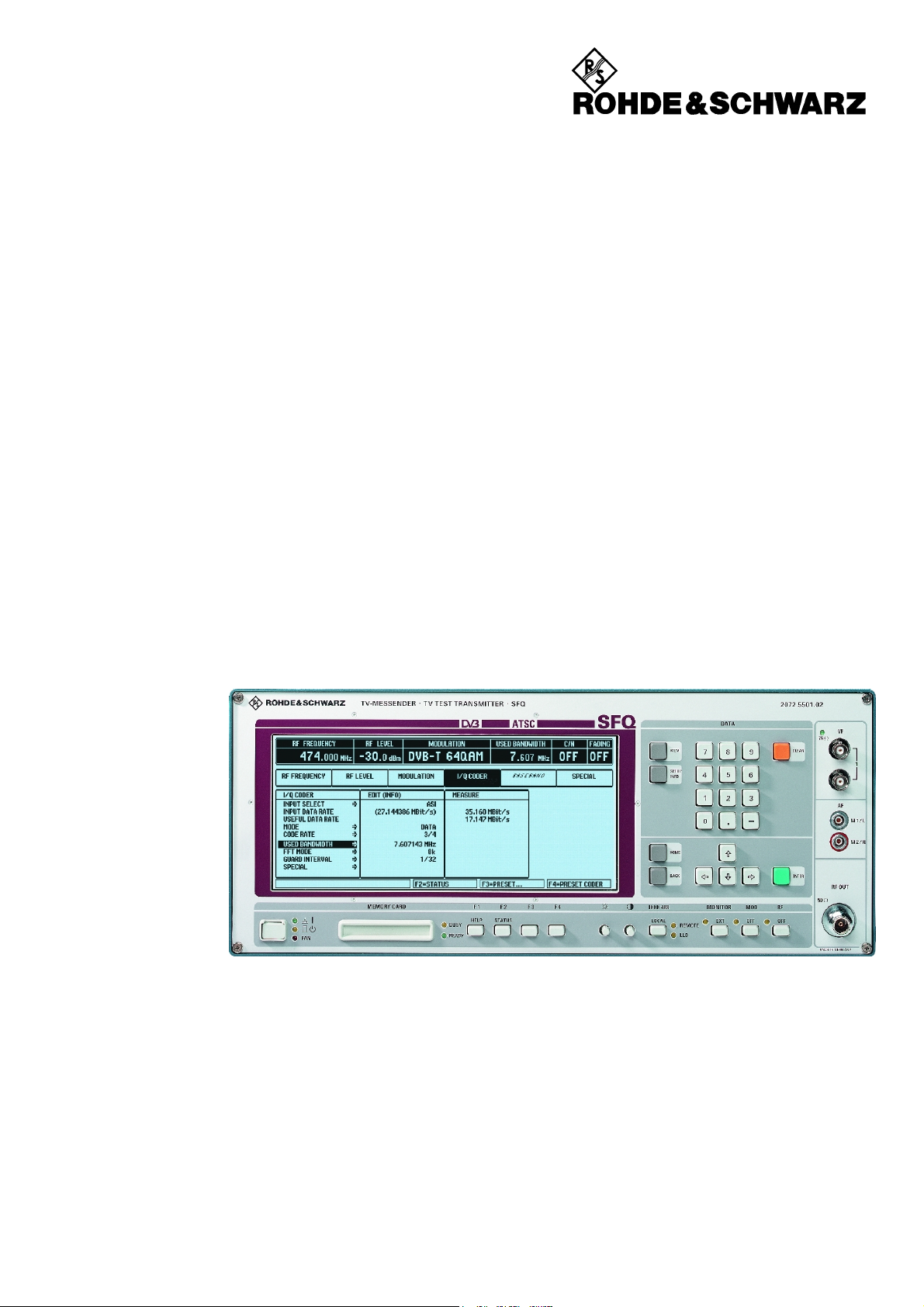
1 Preparation for Use
The controls and indicators of the instrument are combined in separately arranged and colour-coded
functional groups. A brief description of these functional groups is given in the f ollowing together with
references to the chapter containing a detailed description.
Chapter 1 Preparation for Use is subdivided as follows:
• Legend for Front and Rear View Chapter 1.1
• Putting into Operation Chapter 1.2
• Connection Chapter 1.3
• Power Up Chapter 1.4
• Configuration Chapter 1.5
• Options Chapter 1.6
1.1 Legend for Front and Rear View
1.1.1 Front View
Fig. 1-1 Front view
POWER Switching on the SFQ
ON LED green; lights if SFQ is switched on
STANDBY LED yellow; lights if SFQ is in standby mode
FAN LED red; lights if fan is not running
DISPLAY
SFQ has an LCD display with CGA mode for menu display
with a resolution of 640 x 200 pixels.
2072.5724.02 E-111.1.1
Page 16
Preparation for Use SFQ
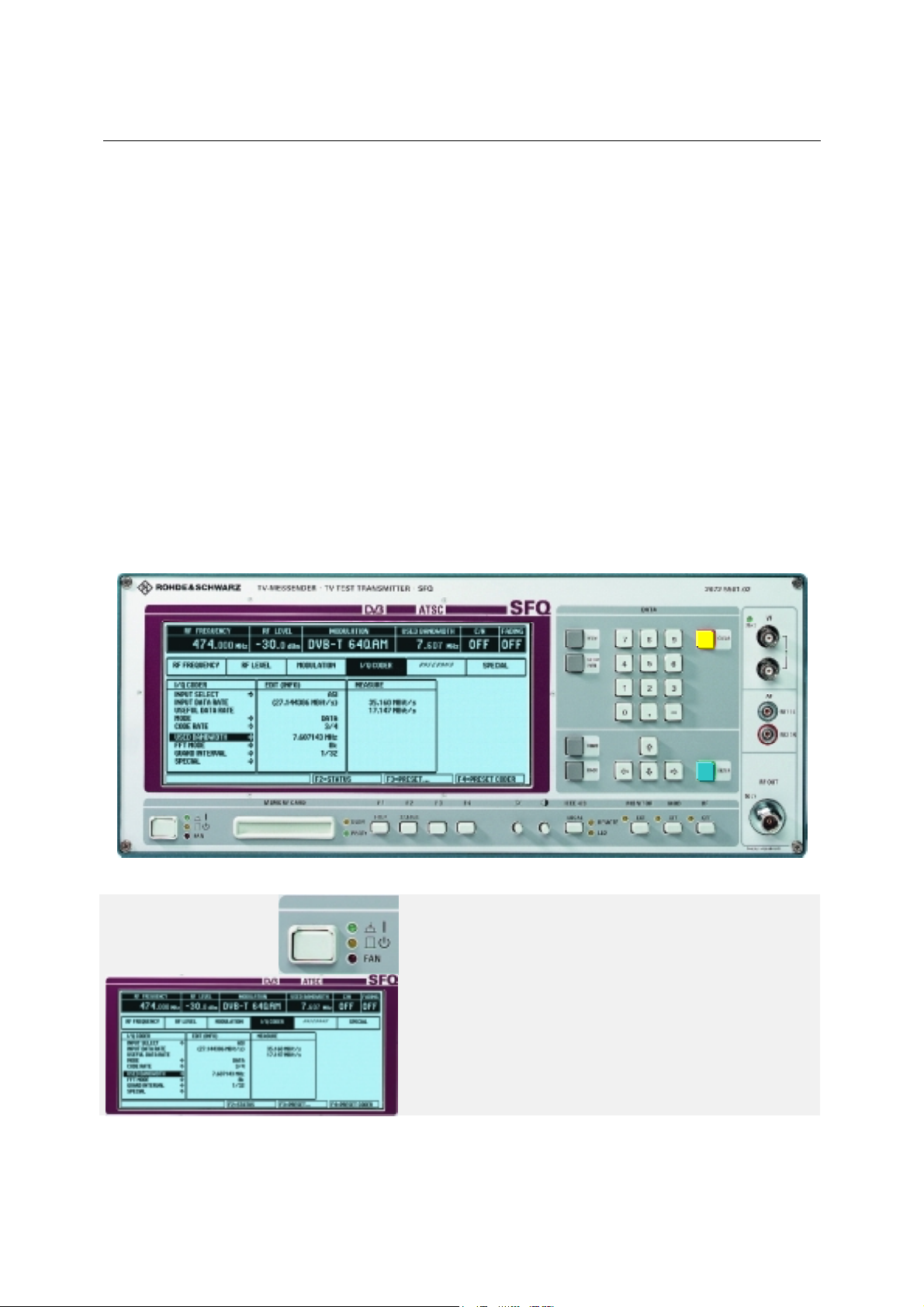
Fig. 1-2 Front View
MEMORY CARD
Memory to PCMCIA standard with 68-pin connector. Instrument settings
can be stored on the MEMORY CARD and recalled.
F1 to F4
F1 shows the help menus
F2 shows in a menu all set values
F3/F4 are function keys assigned varying functions.
Adjusting Screen Contrast and Brightness
IEEE 488
With IEEE-bus operation, the LOCAL key switches to local (front-panel)
control unless this is inhibited by local lockout. Local lockout status is
indicated by the LLO LED.
IEEE-bus operation is indicated by the REMOTE LED.
MONITOR Switchover key for LCD display/external monitor
MOD Modulation ON/OFF key
RF RF ON/OFF key
2072.5724.02 E-111.1.2
Page 17
SFQ Preparation for Use
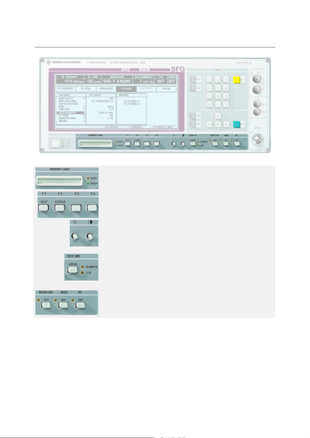
Fig. 1-3 Front View
DATA Keyboard for numeric data entry. Entry is terminated
with the ENTER key.
MEM Operation of MEMORY CARD, memory management
SETUP In the associated menu displayed on the screen
INFO basic settings can be made, e.g. the definition of
interfaces.
CLEAR Reset of numeric entries.
Only SFQ with option SFQ-B2:
CURSOR KEYS
The CURSOR keys are provided for menu-guided operation and
for stepwise variation of data variables.
An entry is terminated with the ENTER key.
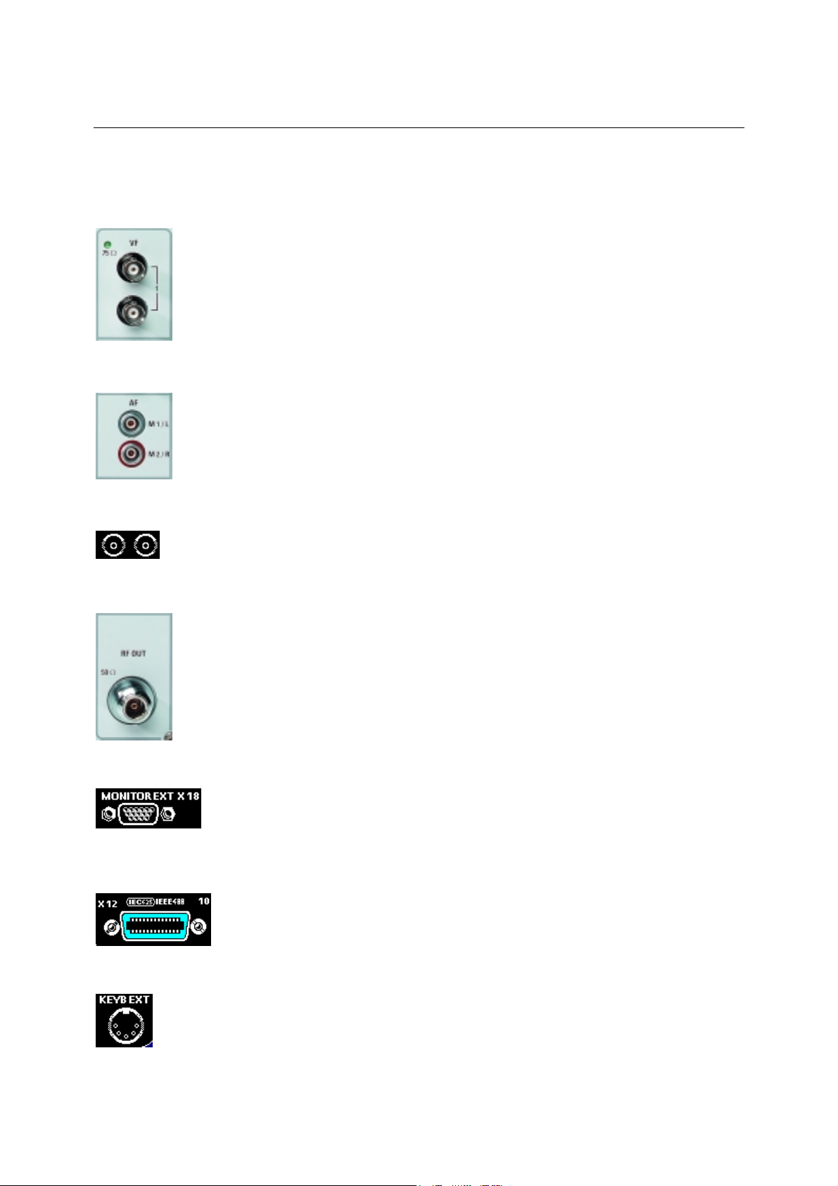
RF OUT
RF N female connector, 50 Ω
VF
Output and input (loopthrough filter) for the video signal
(only available if option SFQ-B2 is fitted)
With internal 75 Ω termination the green LED lights.
AF
M1/L Input M1 or left channel
M2/R Input M2 or right channel
2072.5724.02 E-111.1.3
Page 18
Preparation for Use SFQ
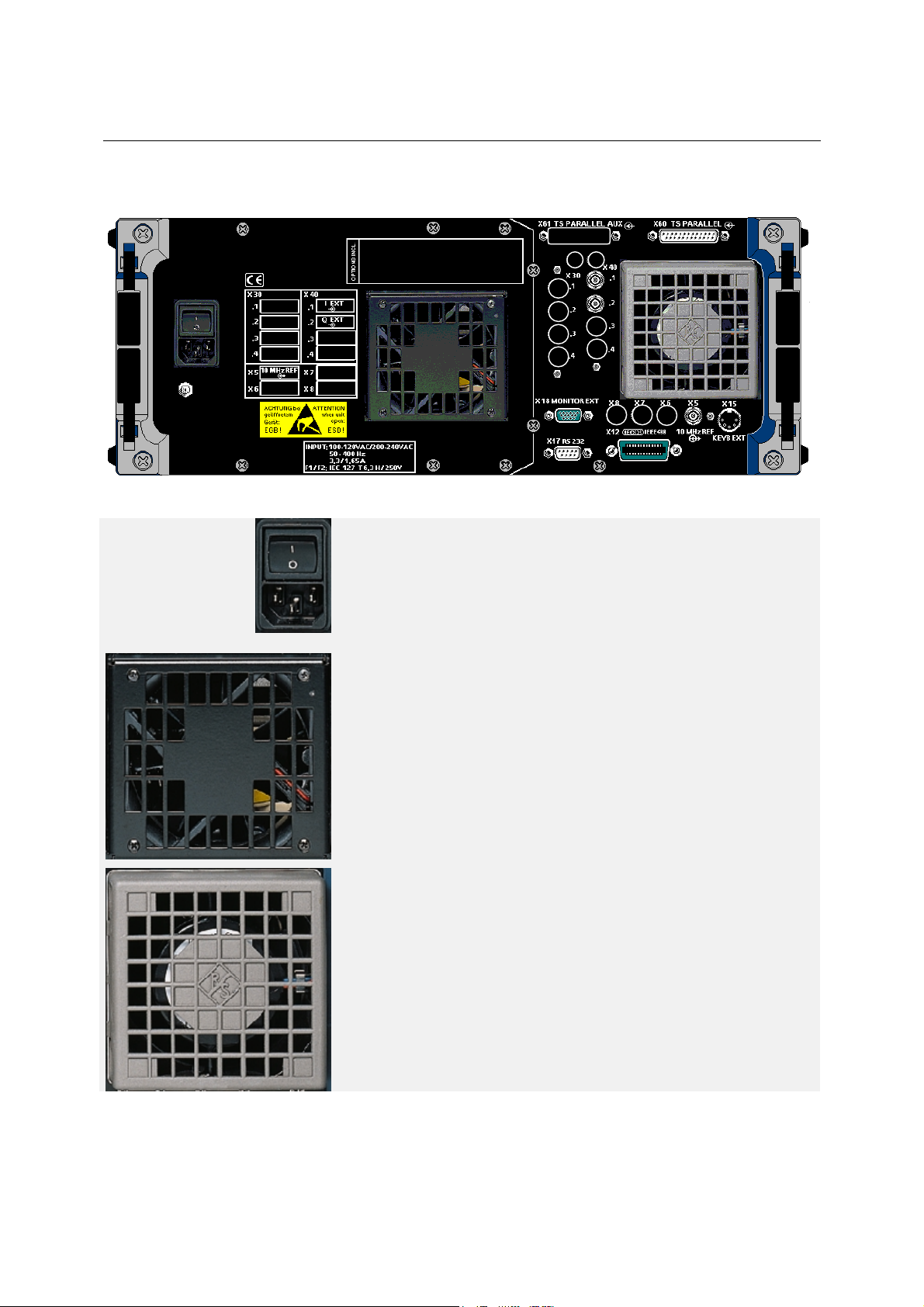
1.1.2 Rear View
Fig. 1-4 Rear View
AC SUPPLY CONNECTION
Power switch
AC supply connector X1
100/120 V : IEC127-T3.15L / 250 V
220/230 V : IEC127-T1.6L / 250 V
Setting to the correct AC supply voltage is made automatically.
FAN 1
Sucks in cooling air
Note: The fan should not be covered up in order to avoid
overheating of the unit !
FAN 2
expels air.
Note: The fan should not be covered up in order to avoid
overheating of the unit!
2072.5724.02 E-111.1.4
Page 19
SFQ Preparation for Use
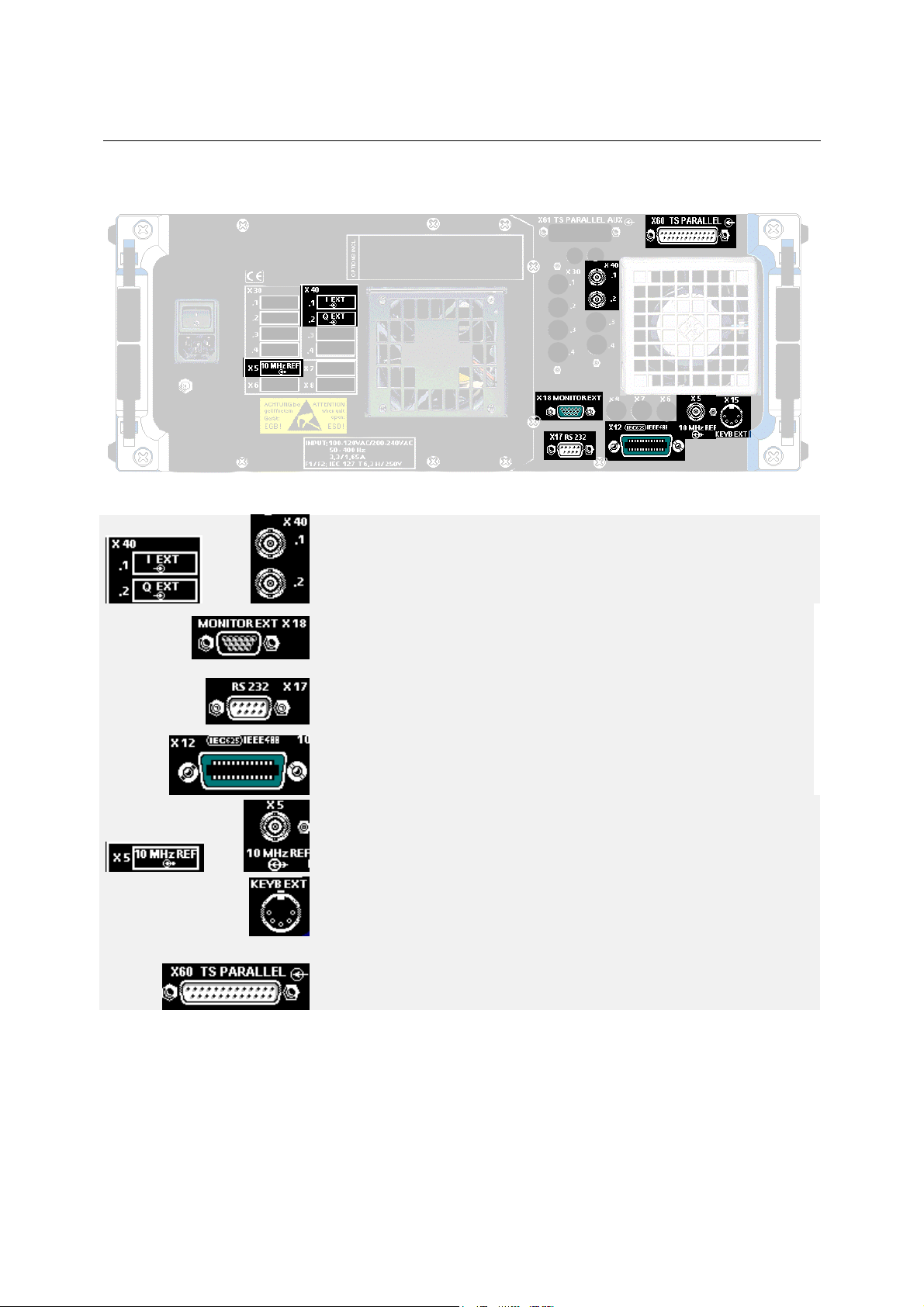
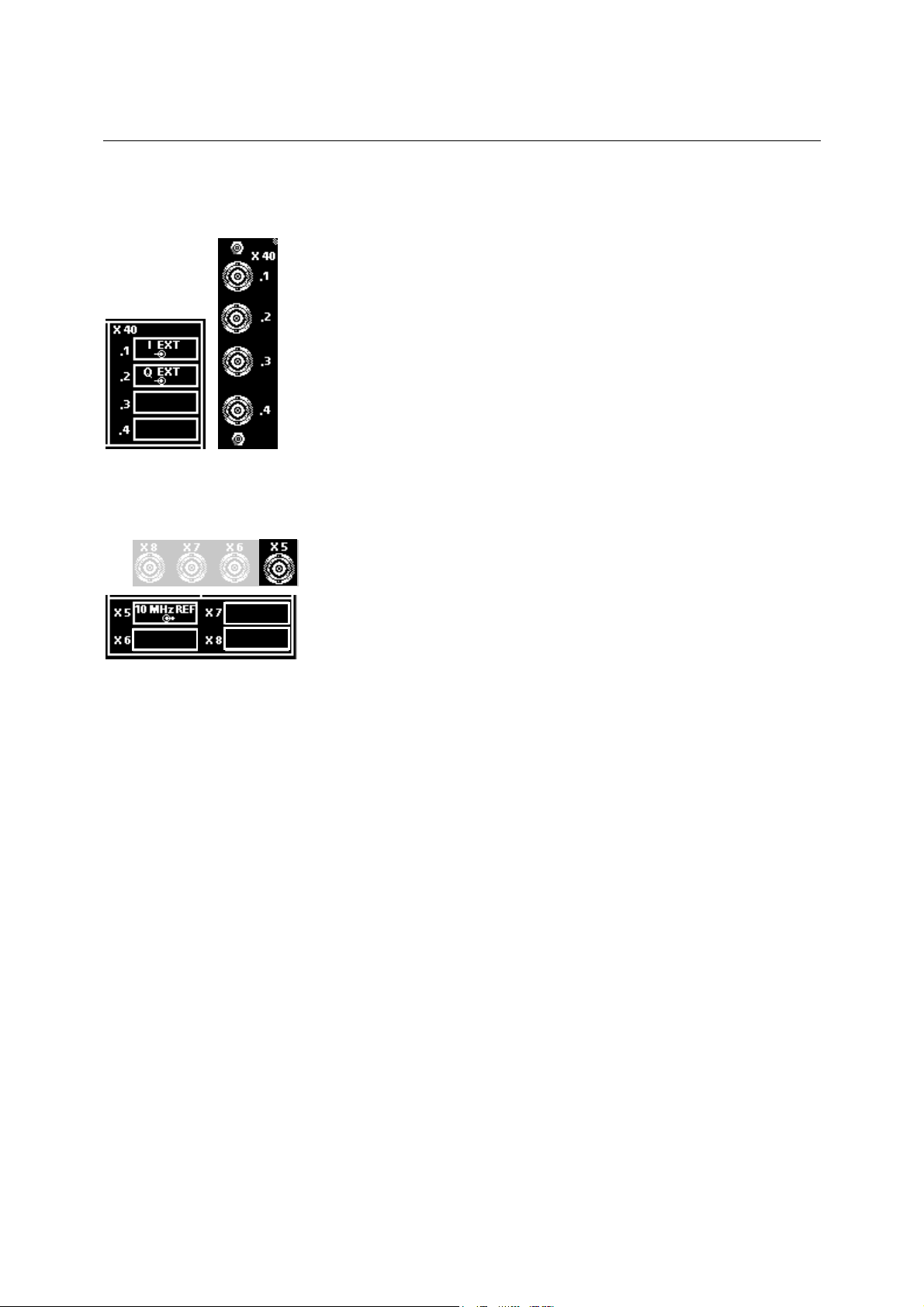
1.1.2.1 Standard Pin Assignments
Fig. 1-5 Standard Pin Assignments
X 40
.1 I EXT, input for external I signals
.2 Q EXT, input for external Q signals
MONITOR EXT X 18
Monitor connector, female
RS 232 X 17
RS-232 connector, female
IEC625/IEEE488 X 12
IEC/IEEE-bus connector, see chapter 3
X5 10 MHz REF, input / output
KEYB EXT An external keyboard allows for manual control of all
instrument functions . In addition, any alphanumeric entries
can be made in appropriate menus.
X 60 Input TS PARALLEL
2072.5724.02 E-111.1.5
Page 20
Preparation for Use SFQ
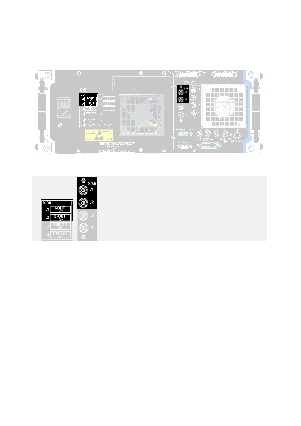
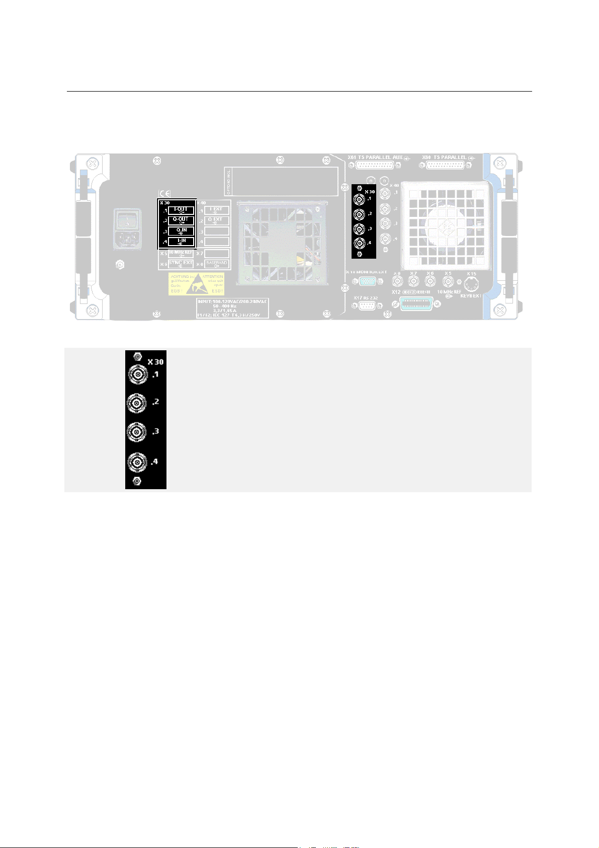
1.1.2.2 Additional Pin Assignments with SFQ-Z5
Fig. 1-6 SFQ-Z5
SFQ-Z5 Diversity Cable Set 2081.9158.02
X 30
.1 I-OUT, Output
.2 Q-OUT, Outut
2072.5724.02 E-111.1.6
Page 21
SFQ Preparation for Use
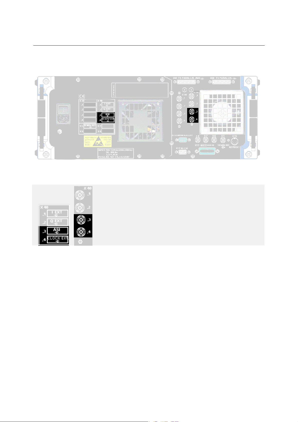
1.1.2.3 Additional Pin Assignments with
SFQ-B6 INPUT INTERFACE 2072.7679.02/03
Fig. 1-7 SFQ-B6
SFQ-B6 INPUT INTERFACE 2072.7679.02/03
X 40
.3 With the INPUT INTERFACE option SFQ-B6 fitted, this connector is
used as a transport stream input for ASI. If option SFQ-B6 m odel 03
is fitted, this connector may also be used as an SMPTE310 input.
.4 If the INPUT INTERFACE option SFQ-B6 is fitted, this connector is
used as an input for the ASI EXT. CLOCK and SPI EXT. CLOCK
2072.5724.02 E-111.1.7
Page 22
Preparation for Use SFQ
1.1.2.4 Additional Pin Assignments with Option SFQ-B10
Fig. 1-8 Additional Pin Assignments with Option SFQ-B10
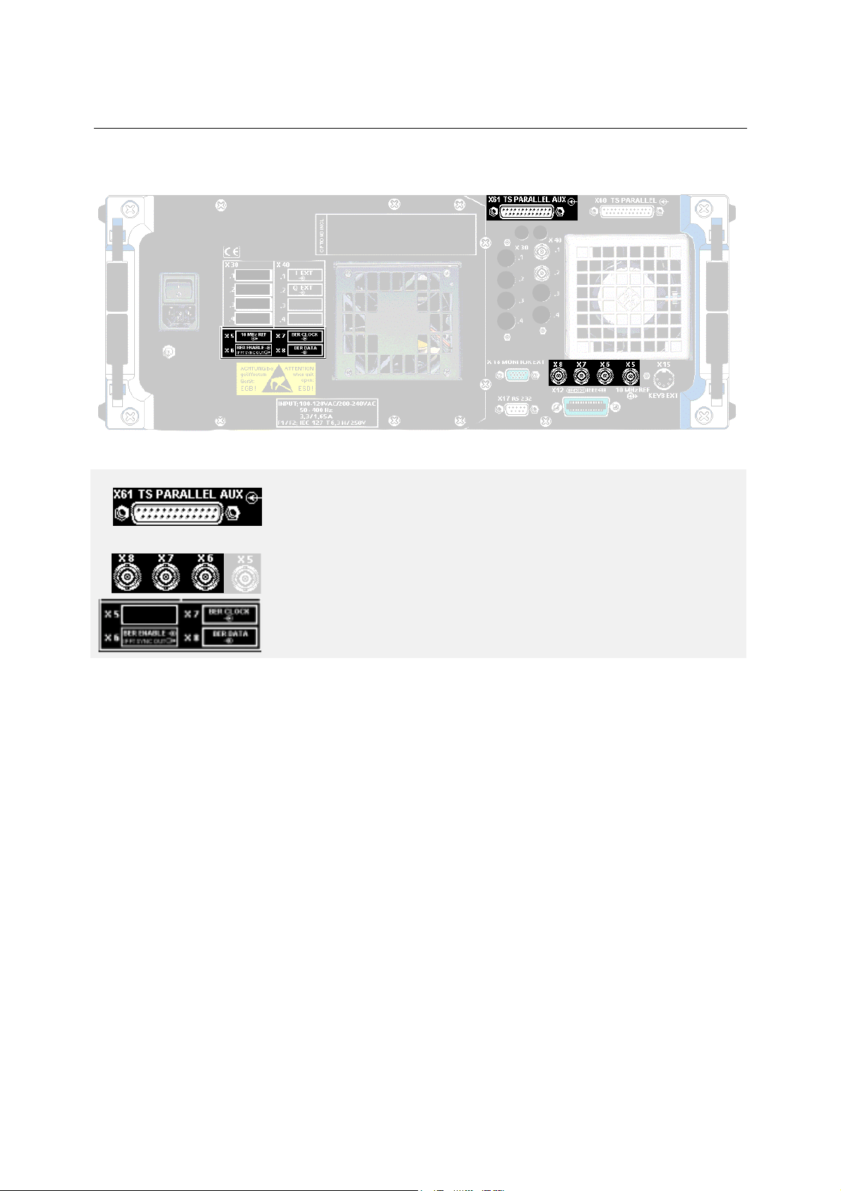
X 61 Input TS PARALLEL AUX
for hierarchical coding to DVB-T (option SFQ-B16)
X 5 to X8
Note: Labelling for X6 to X8 depends on the option,
the labelling for option SFQ-B17 is shown here.
X6 BER ENABLE / IFFT SYNC OUT, input/output (option B17)
X7 BER CLOCK, input (option SFQ-B17)
X8 BER DATA , input (option SFQ-B17)
2072.5724.02 E-111.1.8
Page 23
SFQ Preparation for Use
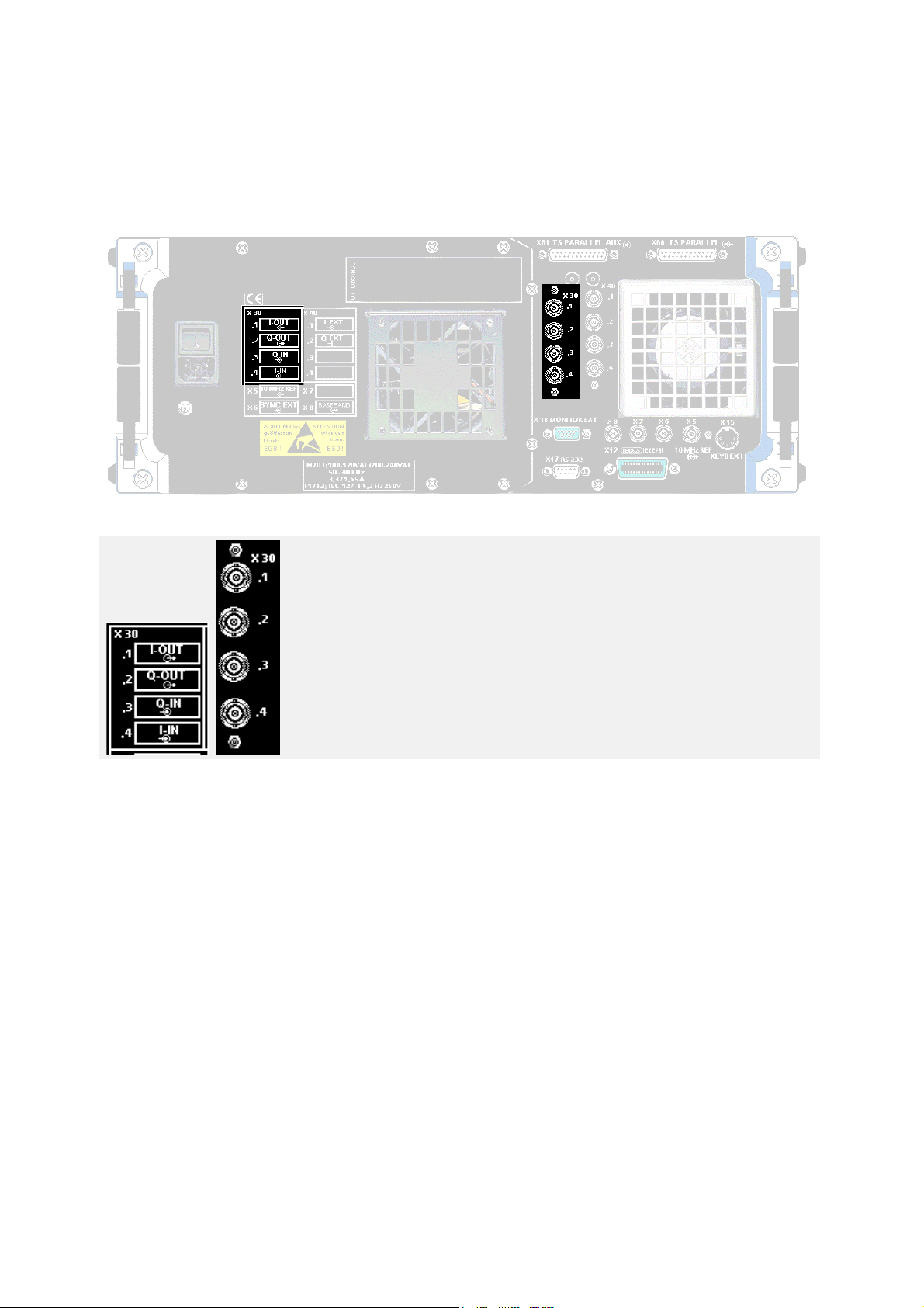
1.1.2.5 Additional Pin Assignments with SFQ-B14 IQ OUTPUT/INPUT 2072.6266.02
Fig. 1-9 SFQ-B14
X 30 With option SFQ-B14 installed
.1 I-OUT
.2 Q-OUT
.3 Q-IN
.4 I-IN
2072.5724.02 E-111.1.9
Page 24
Preparation for Use SFQ
1.1.2.6 Additional Pin Assignments with SFQ-B27 Impulsive Noise 2110.0407.02
Fig. 1-10 SFQ-B27
X 30 With option SFQ-B27 installed
.1
.2
.3 Noise Gate
.4
2072.5724.02 E-111.1.10
Page 25
SFQ Preparation for Use
Kap
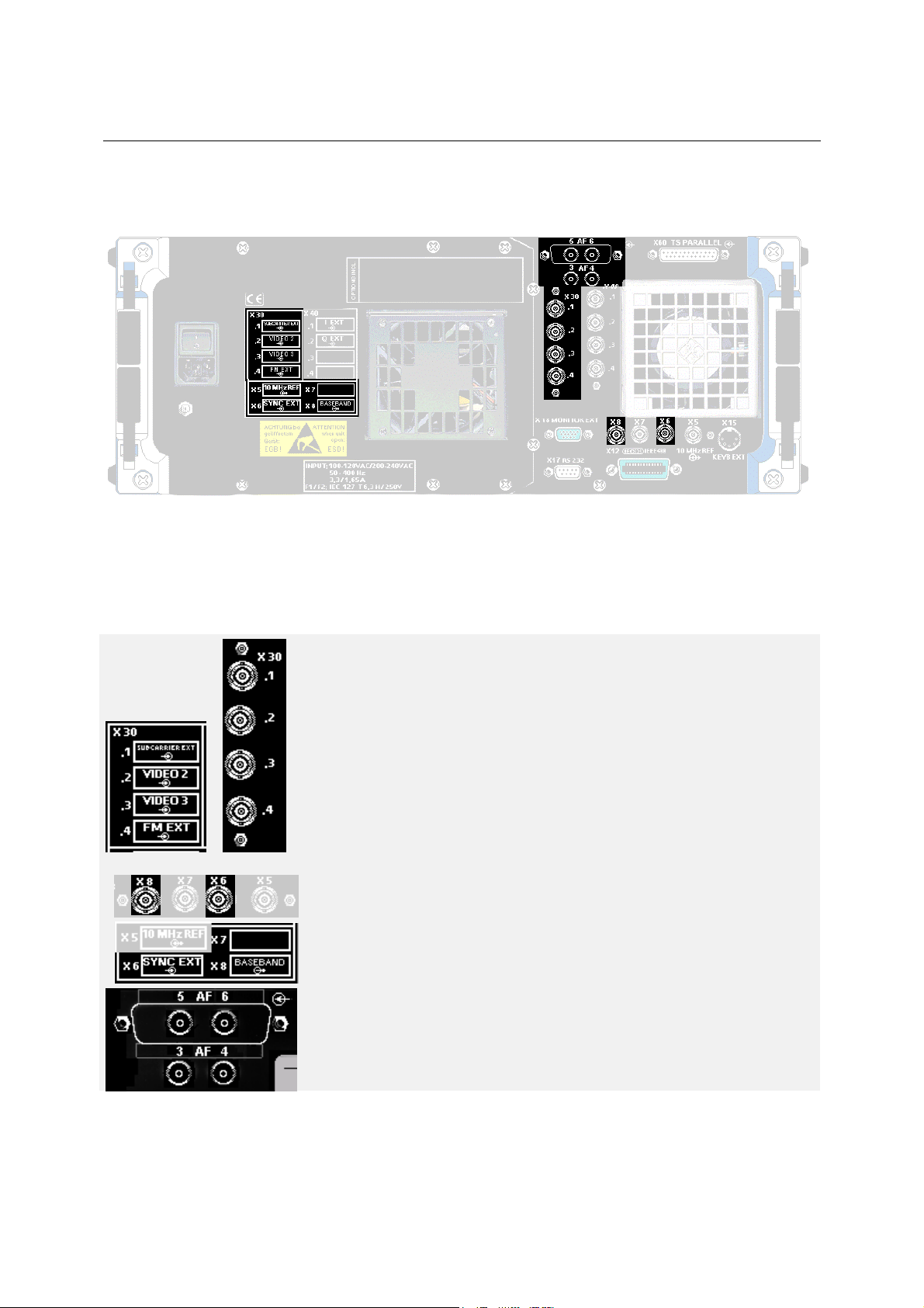
1.1.2.7 Additional Pin Assignments with SFQ-B2, -B3 and -B4
Fig. 1-11 SFQ-B2; -SFQ-B3; SFQ-B4
SFQ-B2 FM MODULATOR 2072.6108.02
SFQ-B3 FM SUBCARRIER 2072.7379.02
SFQ-B4 ADR SUBCARRIER 2072.7479.02
1
X 30 With option SFQ-B2 installed
.1 SUBCARRIER EXT, input
.2 VIDEO 2, input
3. VIDEO 3, input
.4 FM EXT, input
i
X 5 to X8
X6 SYNC EXT, input
X7
X8 BASEBA ND, output
AF 5/6 AF connectors
Note: AF connectors 3, 4, 5 and 6 are fitted but not connected
when option SFQ-B2 is installed. They are only required for
options SFQ-B3 and SFQ-B4.
2072.5724.02 E-111.1.11
Page 26

Preparation for Use SFQ
2072.5724.02 E-111.1.12
Page 27

SFQ Putting into Operation
1.2 Putting into Operation
see also section 1.1, Legend for Front and Rear View
Prior to putting the instrument into operation make sure that
• the setting for the available AC supply voltage is correct (see section 1.3.1),
• signal levels applied to the inputs do not exceed permissible limits,
• the instrument is operated within the permissible temperature range (permissible ambient
temperature range +5°C to +45°C),
• the fan at the rear of the instrument is not obstructed (to prevent overheating of the unit),
• the outputs of the instrument are not overloaded or wrongly connected.
Warning:
Input voltages above permissible limits (see data sheet) may cause the instrument to
be damaged.
1.2.1 Positioning the Instrument
The instrument is equipped with feet that can be folded out at the instrument front to f acilitate operation.
To do so lift up the instrument at the front and swing down the feet.
The instrument is constructed so that its operating temperature remains sufficiently low even in
continuous operation. When the unit is used as a benchtop make sure that the air vents are not
obstructed to prevent the instrument being overheated - especially during continuous operation.
Sufficient ventilation must also be ensured when the unit is rackmounted. .
1.2.2 EMC Safety Precautions
Warning:
To prevent electromagnetic interference the ins trument should be operated closed and
with all screening covers fitted. Take the appropriate measures when calibrating the
open instrument. Make sure that only suitable, screened IEC/IEEE-bus cables are used.
2072.5724.02 E-111.2.1
Page 28

Putting into Operation SFQ
1.3 Connecting the Instrument
1.3.1 AC Supply Connection
The instrument m ay be operated at 90 V to 132 V and 180 V to 265 V AC at frequencies from 47 Hz to
440 Hz. The AC supply connector is at the rear of the unit. T he inst rument automatically sets its elf to the
applied voltage by selecting one of the two permissible voltage ranges. Adjusting the instrum ent to a
particular AC supply voltage is therefore not required.
When the instrum ent is switched off, an "O" is visible above the power switch which may be on for any
period of time. The ins trument need only be switched off when it is to be c ompletely disconnected f rom
the AC supply.
1.3.2 MPEG2 Signal Feed for Vector Modulation
1.3.2.1 ASI Connector
Connector for feeding in an external MPEG2 transport stream.
If option SFQ-B6 INPUT INT ERFACE is installed, the connec tor X40.3 serves as a tr ansport
stream input for ASI.
If model 03 of option SFQ-B6 INPUT INTERFACE is fitted, connector X40.3 may also be
used as an SMPTE310 input for certain modulation modes.
1.3.2.2 TS PARALLEL Connector
Connector for feeding in an external MPEG Transport Stream through
TS PARALLEL.
If option SFQ-B6 INPUT INT ERFACE is installed, this connector serves as a
transport stream input for SPI and TS PARALLEL.
2nd connector for feeding in a second external transport stream for
hierarchical coding in DVB-T mode.
(TS PARALLEL AUX or SPI AUX).
Depending on the model, there may be AF connectors in place of
TS PARALLEL AUX connector.
2072.5724.02 E-111.3.2
Page 29
SFQ Putting into Operation
A
1.3.3 Exter nal I / O Si gnal Feed for Vector Modulation
Feed-in through connectors X40.1 and X40.2.
X 40
.1 I EXT, input for external signals
.2 Q EXT, input for external signals
.3 If the option SFQ-B6 INPUT INTERFACE is installed, this connec tor
serves as a transport stream input for ASI.
.4 If the option SFQ-B6 INPUT INTERFACE is installed, this connec tor
serves as an external clock input for
EXT. CLOCK.
SI EXT. CLOCK and SPI
1.3.4 10 MHz REF Input/Output
X5: 10 MHz REF input or output.
X6 to X8 are system connectors and are wired and labelled according to
the options fitted.
2072.5724.02 E-111.3.3
Page 30
Putting into Operation SFQ
1.3.5 Feed-i n of Analog Video/Sound Signal s for FM Modulation
1.3.5.1 VF Connector
Connector VF (BNC) is a video input with a loopthrough filter. Either of the connectors can
be used as an input or output. With an internal termination into 75 Ω the yellow LED lights.
In this case the output of the loopthrough filter must not be terminated into 75 Ω.
The input level is 1 V pp. All modulator settings are calibrated to this input level.
1.3.5.2 AF Connector, Front Panel
The displayed frequency deviation applies to an AF input level of +9 dBm with
preemphasis switched off.
The input impedance is >5 kΩ.
1.3.5.3 AF Connectors, Rear Panel (for Additional Sound Subcarriers)
AF connectors (only with option SFQ-B3 fitted),
or CLK and DATA connectors (only with option SFQ-B4 fitted)
labelled ADR CLK / ADR DATA.
1.3.6 RF Connector
The RF output provides signals between 0.3 MHz and 3.3 GHz.
In the SETUP/PRESET menu, the units dBm, dBµV or mV c an be selec ted for RF LEVEL
entry.
1.3.7 External Monitor
Multisync VGA monitors with 32-kHz horizontal frequency are suitable for
connection.
The display is of CGA resolution.
1.3.8 RS-232 Interface
For data transmission and remote control from a detached PC the two RS-232
connectors are to be linked by a cable.
1.3.9 KEYBOARD Connector
A standard PC keyboard may be connected to the 5-contact keyboard connector.
2072.5724.02 E-111.3.4
Page 31

SFQ Putting into Operation
V
1.3.10 Synchronization of SFQ Data Rate without Input Interface with External Clock
Note:
This chapter is only relevant for units without INPUT INTERFACE.
External synchronization is not required for units with input interface or can easily be
performed via connector X40.4
(ASI EXT CLOCK, SPI EXT CLOCK).
The data rate of MPEG2 transport stream packets can be given in different ways in SFQ:
1. The internal PRBS or NULL TS PACKETS are modulated and determ ine the clock and s ymbol rate.
The internal free-running VCO is used for clock generation. Free-running does however not imply
high clock accuracy.
2. An ex ternal MPEG2 data stream synchronizes the whole SFQ clock hous ekeeping via the MPEG2
data input TS PARALLEL. Data clock and symbol clock are as accurate as the applied signal.
3. W ith its crystal-controlled clock, the INPUT INTERFACE deter mines the data rate and the symbol
rate of PRBS and NULL TS PACKETS.
It is often that neither an MPEG2 data stream nor the INPUT IN TERFACE is available. SFQ still has to
guarantee the specified data and symbol rates for the internal PRBS and NULL TS PACKETS.
The solution is the synchronization of SFQ by means of an ex ternal sinewave generator providing the
required accuracy. Such generators are always available in labs and service center s . R&S gener ators of
this type are in all members of the R&S family SMX, in AFG and AFGU, ADS etc.
Preconditions
The firmware version of SFQ should be 1.04 or higher.
Preparation for Use
An adapter cable is to be connected to the TS PARALLEL input on the rear of SFQ accor ding to the
following figure:
14
75 Ohm
1
iew of solder contacts
25
13
Fig. 1.3-1 Adapter Cable
2072.5724.02 E-111.3.5
Page 32

Putting into Operation SFQ
The sync signal is applied to the adapter via the coaxial cable with BNC connector. T he outer conduc tor
is soldered to pin 14 of the 25-pin connector and the inner conductor to pin 1 via a 75 Ω protective
resistor. Two anti-parallel diodes ( 1N4448 or similar Si diodes) are provided between pin 1 and pin 14
and prevent too high input voltages.
A sinewave signal of the signal generator can now be applied to the clock input ( pin 1 c lock input, pin 14
is grounded) of the TS PARALLEL interface. The 8-bit wide MPEG2 TS data are missing.
Calculation of TS Data Rate Frequency
The frequency to be set for the desired TS data rate at the signal generator is to be c alculated. A byte of
MPEG2 TS data is read by the TS PARALLEL interface with one clock of frequency f
given in bit/sec. The frequency to be selected is therefore calculated as follows:
. The clock rate is
C
f
Generator
= fC / 8.
For a simulation of the cable clock rate of 38.152941 Mbit/sec the following has to be set:
f
Generator
= 4.7691176 MHz
(Exact values were used. The normal accuracy is 38.15 Mbit/sec.)
Permissible Amplitude of Applied Sinewave
Now a sinewave of permissible am plitude needs to be applied via the adapter. Since the anti-parallel
diodes limit the signal to approx. ±0.7 V the am plitude should be within the lim its 1.4 V <V
<3 V. A DC
pp
voltage offset must not be available.
Further SFQ Settings
After SFQ has synchronized to the applied clock, the m essage FRMERR (Fram e Error) is displayed in
the status bar field "I/Q Coder". This message signifies that a clock is being applied to the TS
PARALLEL interface but that the MPEG2 TS data are invalid or not packetized and not provided with the
SYNC WORD. W ith synchronism established following the measurement of the clock rate in the I/Q
Coder menu and acceptance of the clock rate with F3 ACCEPT, NULL TS PACKET S can be selected
as a modulation source. SFQ then generates and modulates T S packets in QAM or Q PSK with a valid
sync word 47 hex using the data rate determined by the sinewave generator.
Circuit diagram
SMG, SMH ...
SMT, SME...
Fig. 1.3-2 Circuit diagram
2072.5724.02 E-111.3.6
75 Ohm
2 x Si Diode
Adapter
SFQ
QAM/QPSK-modulated
NULL TS PACKETs
Page 33

SFQ Putting into Operation
1.4 Switching On
The instrument is switched on by pressing the power switch at the rear and the
POWER key at the front panel.
For a temporary switch-off, the STANDBY mode is selected by pressing the
POWER key.
The red FAN LED lights if the fan is not active or defective.
1.4.1 Adjusting Screen Contrast and Brightness
The screen contrast is adjusted by means of the right control knob (2), the
brightness with the left control (1) below the display.
12
1.4.2 Non-Volatile Memory
If the lithium battery on the controller board of the instrum ent is flat, settings c an no longer be stored in
the non-volatile memory. To replace the battery refer to section 4.5.
2072.5724.02 E-111.4.7
Page 34

Putting into Operation SFQ
2072.5724.02 E-111.4.8
Page 35

SFQ Putting into Operation
1.5 Instrument Configurations
1.5.1 Model .02
A22
A11
B10
A27
A15
Slot: Module:
A15 AC SUPPLY .......................................
A26 MOTHERBOARD...............................
A10
A9
A8
A7
A6
A5
A4 SYNTHESIZER..................................
A3 I/Q CONVERTER ...............................
A2 I/Q MODULATOR...............................
A1 CONTROLLER..............
A11
A13
A22 ATTENUATOR..............
B10 DC/AC CONVERTER....
A27 KEYBOARD ..................
CODER options
(a coder is always fitted)
SFQ-B10 DVB-T CODER 2072.6166.02
SFQ-B12 ATSC/8VSB CODER 2072.6220.02
SFQ-B13 ITU/J83B CODER 2072.6243.02
SFQ-B15 DVB-C/S CODER 2072.5976.02
SFQ-B21 DVB-C CODER 2081.9812.02
SFQ-B23 DVB-S CODER 2072.5830.02
Order No. of PCB:
1039.1510.00
2072.7004.04
1039.2330.02
1084.9300.04
1084.9800...
2008.0260.04
1008.7375.02
0840.5698.00
2008.0125.02
Fig. 1.5-1 Layout of modules
2072.5724.02 E-111.5.1
Page 36

Putting into Operation SFQ
1.5.1.1 SFQ equipped with SFQ-B2, SFQ-B3, SFQ-B4 and SFQ-B6
A11
A15
Slot: Module:
A15 AC SUPPLY ...........................................
A26 MOTHERBOARD...................................
A10 CODER option
A9 SFQ-B3 FM sound subbcarriers .............
SFQ-B4 ADR sound subbcarriers...........
A8 SFQ-B3 FM sound subcarriers ...............
SFQ-B4ADR sound subcarriers..............
A7 SFQ-B2 FM sound subcarriers ...............
A6 SFQ-B2 baseband..................................
A5 SFQ-B2 BB-FM modulator noise. ...........
A4 SYNTHESIZER......................................
A3 I/Q CONVERTER ...................................
A2 I/Q MODULATOR...................................
A1 CONTROLLER.......................................
A11 SFQ-B6 INPUT INTERFACE..................
Order No. Of PCB:
1039.1510.00
2072.7004.04
2072.7379.02 or
2072.7479.02
2072.7379.02 or
2072.7479.02
2072.6108.02
2072.6108.02
2072.6108.02
1039.2330.02
1084.9300.04
1084.9800...
2008.0260.04
2072.7679.03
B1
A27
Fig. 1.5-2 Layout of modules
2072.5724.02 E-111.5.2
A13 VIDEO SELECTOR................................
A22 ATTENUATOR.......................................
B10 DC/AC CONVERTER.............................
A27 KEYBOARD ...........................................
2008.0425.02
1008.7375.02
0840.5698.00
2008.0125.02
Page 37

SFQ Putting into Operation
1.5.1.2 SFQ equipped with SFQ-B5, SFQ-B6, SFQ-B11 model .02, SFQ-B11 model .04 and coder option
A11
A15
Slot: Module:
A15 AC SUPPLY .............................................
A26 MOTHERBOARD .....................................
A10 CODER option
A9
A8
A7 SFQ-B11 FADING SIM. 7 to 12 ................
A6 SFQ-B11 FADING SIM. 1 to 6 ..................
A5 SFQ-B5 NOISE GENERATOR ...............
A4 SYNTHESIZER ......................................
A3 I/Q CONVERTER ...................................
A2 I/Q MODULATOR...................................
A1 CONTROLLER.......................................
A11 SFQ-B6 INPUT INTERFACE..................
Order No. of PCB:
1039.1510.00
2072.7004.04
2072.6189.04
2072.6189.02
2072.7579.03
1039.2330.02
1084.9300.04
1084.9800...
2008.0260.04
2072.7679.03
B10
Fig. 1.5-3 Layout of modules
2072.5724.02 E-111.5.3
A22 ATTENUATOR .......................................
B10 DC/AC CONVERTER.............................
A27 KEYBOARD ...........................................
1008.7375.02
0840.5698.00
2008.0125.02
Page 38

Putting into Operation SFQ
1.5.1.3 SFQ equipped with SFQ-B5, SFQ-B6, SFQ-B10, SFQ-B11 model .02, SFQ-B11 model .04, SFQ-B12, SFQ-B13, SFQ-B15, SFQ-B21 and SFQ-B23
A11
Slot: Module:
A15 AC SUPPLY ..................................................
A26 MOTHERBOARD ..........................................
A10 SFQ-B10 DVB-T CODER ..............................
A9 SFQ-B12 ATSC/8VSB CODER .....................
A8
A7 SFQ-B11 FADING SIM. 7 to 12 .....................
A6 SFQ-B11 FADING SIM. 1 to 6 .......................
A5 SFQ-B5 NOISE GEN. ...................................
A4 SYNTHESE ...................................................
A3 I/Q CONVERTER ..........................................
A2 I/Q MODULATOR..........................................
A1 CONTROLLER..............................................
SFQ-B13 ITU-T/J.83B CODER......................
SFQ-B15 DVB-C/S CODER 2072.5976.02 or
SFQ-B21 DVB-C CODER 2081.9812.02
SFQ-B23 DVB-S CODER 2072.5830.02
Order No. of
PCB:
1039.1510.00
2072.7004.04
2072.6166.02
2072.6220.02 or
2072.6243.02
2072.6189.04
2072.6189.02
2072.7579.03
1039.2330.02
1084.9300.04
1084.9800...
2008.0260.04
Fig. 1.5-4 Layout of modules
2072.5724.02 E-111.5.4
A11 SFQ-B6 INPUT INTERFACE.........................
A22 ATTENUATOR ..............................................
B10 DC/AC CONVERTER....................................
A27 KEYBOARD ..................................................
2072.7679.03
1008.7375.02
0840.5698.00
2008.0125.02
Page 39

SFQ Putting into Operation
1.6 Options
Type Designation Order No. Display in SETUP/HW/ EQUIPMENT
SFQ-B5
SFQ-Z5
SFQ-B6
SFQ-B10
SFQ-B11
SFQ-B11
SFQ-B12
SFQ-B13
SFQ-B14
SFQ-B15
SFQ-B16
SFQ-B17
SFQ-B21
SFQ-B23
SFQ-B18
SFQ-B20
SFQ-B2
SFQ-B3
SFQ-B4
2072.7579.02
NOISE GENERATOR
Diversity Cable Set 2081.9158.02 CABLE **)
INPUT INTERFACE
DVB-T CODER 2972.6166.02 DVB-T CODER 2072.6895.02
FADING SIMULATOR
PATHS 1 to 6
FADING SIMULATOR
PATHS 7 to 12
ATSC / 8VSB/J.83B 2072.6220.02
ITU-T J.83/B CODER 2072.6243.02
IQ OUTPUT/INPUT 2072.6266.02 CABLE
DVB-C/DVB-S CODER 2072.5976.02 IQ CODER 2072.7204.02
DVB-T/HIER. CODING 2072.5976.02
BER MEASUREMENT 2072.7056.02
CODER DVB-C 2081.9812.02
CODER DVB-S 2072.5830.02
POWER SUPPLY UPGRADE 2072.7191.02
MEMORY EXPANSION 2072.6450.02
FM MODULATOR 2072.6108.02
FM SUBCARRIER 2072.7379.02 FM SUBCARRIER 2072.7304.02
ADR SUBCARRIER 2072.7479.02 ADR SUBCARRIER 2072.7404.02
2072.7579.03
2072.7579.04
2072.7679.02
2072.7679.03
2072.6189.02
2072.6189.04
NOISE GEN.
NOISE GEN. II
NOISE GEN. III
INPUT INTERFACE
INPUT INTERFACE II
FADING SIMULATORor1085.4060.02
FADING SIMULATORor1085.4060.02
Enabling 8VSB/J.83B
US CODER 2072.6937.02
Enabling J.83/B
US CODER 2072.6932.02
SOFTWARE *)
SOFTWARE *)
Enabling DVB-C
C/S+ CODER 2081.9829.02
Enabling DVB-S
C/S + CODER 2081.9829.02
-5 V BOARD
POWER SUPPLY
MEMORY CARD
BIOS PROM
BASEBAND
FM SUBCARRIER
VIDEO SELECTOR
BB FM/NOISE GEN.
2072.7504.02
2081.9258.02
2072.7604.02
2081.9329.02
1114.9702.02
1114.9702.02
2081.9635.02
1039.1510.00
2072.6395.02
2072.6414.00
2072.7104.02
2072.7304.02
2008.0425.02
2072.7504.03
*) Retrofitting of hardware see SFQ-B10
**) Retrofitting of hardware see SFQ-B5
I
Installation of Options
For reasons of safety and quality (ISO9001), only adequately equipped Rohde & Schwarz service
centers are allowed to install options that require the instrument to be opened or the calibration seal to
be broken (examples: electrostatically safe workplace, necessary service tools, calibration facilities, etc).
A new calibration seal must be affixed after the option has been installed.
The Update CD describes the Options installation.
2072.5724.02 E-11.6.1
Page 40

Putting into Operation SFQ
2072.5724.02 E-11.6.2
Page 41

SFQ Table of contents Manual Control
2 Manual Control................................................................................... 2.1.1
2.1 Basic Operation ........................................................................................................... 2.1.1
2.1.1 Front Panel .................................................................................................................... 2.1.1
2.1.2 External Keyboard ......................................................................................................... 2.1.2
2.1.3 Switch-On Procedure .................................................................................................... 2.1.3
2.1.4 General Information....................................................................................................... 2.1.4
2.1.4.1 Menu Operation............................................................................................................. 2.1.4
2.1.4.2 Calibration ..................................................................................................................... 2.1.6
2.1.4.3 Software Update............................................................................................................ 2.1.8
2.1.4.4 Enabling Software Options ............................................................................................ 2.1.8
2.2 Menu Operation ........................................................................................................... 2.2.1
2.2.1 RF FREQUENCY Menu................................................................................................ 2.2.1
2.2.1.1 RF FREQUENCY .......................................................................................................... 2.2.1
2.2.1.2 RF FREQUENCY (with VSB Modulation)...................................................................... 2.2.3
2.2.2 RF LEVEL Menu........................................................................................................ 2.2.2.1
2.2.2.1 RF LEVEL................................................................................................................... 2.2.2.2
2.2.3 MODULATION Menu................................................................................................. 2.2.3.1
2.2.3.1 I/Q Vector Modulation................................................................................................. 2.2.3.3
2.2.3.1.1 Satellite....................................................................................................................... 2.2.3.5
2.2.3.1.2 DVB-S QPSK.............................................................................................................. 2.2.3.6
2.2.3.1.3 DVB-C QAM ............................................................................................................... 2.2.3.7
2.2.3.1.4 DVB-T COFDM........................................................................................................... 2.2.3.8
2.2.3.1.5 ITU-T J.83/B ............................................................................................................. 2.2.3.11
2.2.3.1.6 ATSC VSB................................................................................................................ 2.2.3.12
2.2.3.1.7 ISDB-T...................................................................................................................... 2.2.3.13
2.2.3.1.8 I/Q External............................................................................................................... 2.2.3.15
2.2.3.2 MODULATION FM ................................................................................................... 2.2.3.17
2.2.3.2.1 FM internal................................................................................................................ 2.2.3.17
2.2.3.2.2 FM EXTERNAL ........................................................................................................ 2.2.3.18
2.2.4 I/Q CODER Menu ......................................................................................................2.2.4.1
2.2.4.1 Satellite....................................................................................................................... 2.2.4.1
2.2.4.1.1 DVB-DSNG Coding .................................................................................................... 2.2.4.1
2.2.4.1.2 Description of Menu Items.......................................................................................... 2.2.4.3
2.2.4.1.3 Turbo Coding (Option SFQ-B25).............................................................................. 2.2.4.13
2.2.4.1.4 Description of Menu Items........................................................................................ 2.2.4.16
2.2.4.2 DVB-C QAM .............................................................................................................2.2.4.27
2.2.4.2.1 Coding ...................................................................................................................... 2.2.4.27
2.2.4.2.2 Description of Menu Items........................................................................................ 2.2.4.28
2.2.4.3 DVB-S and DVB-C ................................................................................................... 2.2.4.39
2.2.4.3.1 Coding ...................................................................................................................... 2.2.4.39
2.2.4.3.2 Menu description ...................................................................................................... 2.2.4.41
2.2.4.4 DVB-T CODER......................................................................................................... 2.2.4.49
2.2.4.4.1 Non-hierarchical Coding ........................................................................................... 2.2.4.49
2.2.4.4.2 Hierarchical Coding .................................................................................................. 2.2.4.53
2.2.4.4.3 Description of Menu Items for Non-Hierarchical Coding .......................................... 2.2.4.56
2.2.4.4.4 Description of Individual Menu Items with Hierarchical Coding............................... 2.2.4.68
2.2.4.5 ITU-T J.83/B ............................................................................................................. 2.2.4.75
2.2.4.5.1 Coding ...................................................................................................................... 2.2.4.75
2.2.4.5.2 Description of Menu Items........................................................................................ 2.2.4.79
2.2.4.6 ATSC 8VSB.............................................................................................................. 2.2.4.87
2.2.4.6.1 Coding ...................................................................................................................... 2.2.4.87
2.2.4.6.2 Description of Menu Items........................................................................................ 2.2.4.90
2.2.4.7 ISDB-T...................................................................................................................... 2.2.4.95
2.2.4.7.1 Overview................................................................................................................... 2.2.4.95
2.2.4.7.2 Characteristics of ISDB-T ......................................................................................... 2.2.4.95
2.2.4.7.3 Transmission Parameters ........................................................................................ 2.2.4.96
2.2.4.7.4 Terminology.............................................................................................................. 2.2.4.96
2072.6489.12 E-112.1
Page 42

Table of contents Manual Control SFQ
2.2.4.7.5 Channel Coding........................................................................................................ 2.2.4.97
2.2.4.7.6 Modulation ................................................................................................................ 2.2.4.98
2.2.4.7.7 Description of Menu Items........................................................................................ 2.2.4.99
2.2.4.8 Input Interface......................................................................................................... 2.2.4.111
2.2.4.8.1 Structure of the MPEG-2 Transport Stream ........................................................... 2.2.4.111
2.2.4.8.2 Method of Operation of the Input Interface............................................................. 2.2.4.112
2.2.4.8.3 MPEG-2 Transport Stream Inputs.......................................................................... 2.2.4.112
2.2.4.8.4 Input for External Clock ..........................................................................................2.2.4.114
2.2.4.8.5 Partial Transport Streams ...................................................................................... 2.2.4.115
2.2.5 BASEBAND Menu..................................................................................................... 2.2.5.1
2.2.5.1 VIDEO ........................................................................................................................ 2.2.5.2
2.2.5.2 ENERGY DISPERSAL ...............................................................................................2.2.5.4
2.2.5.3 BASEBAND - SUBCARRIER FM ............................................................................... 2.2.5.5
2.2.5.4 BASEBAND - SUBCARRIER ADR............................................................................. 2.2.5.8
2.2.6 SPECIAL Menu.......................................................................................................... 2.2.6.1
2.2.6.1 SWEEP START/STOP Submenu .............................................................................. 2.2.6.1
2.2.6.2 SWEEP CENTER/SPAN............................................................................................ 2.2.6.2
2.2.6.3 BER submenu ............................................................................................................ 2.2.6.4
2.2.7 NOISE ........................................................................................................................ 2.2.7.1
2.2.7.1 Operation.................................................................................................................... 2.2.7.1
2.2.7.2 Impulsive Noise ..........................................................................................................2.2.7.4
2.2.7.3 Testing diversity receivers: ......................................................................................... 2.2.7.4
2.2.8 FADING...................................................................................................................... 2.2.8.1
2.2.8.1 FADING PARAMETER Submenu .............................................................................. 2.2.8.3
2.2.8.2 Special Level Conditions in Case of Fading ............................................................. 2.2.8.10
2.2.9 BER (Bit Error Ratio) Measurement........................................................................ 2.2.9.1
2.2.9.1 Inputs.......................................................................................................................... 2.2.9.1
2.2.9.1.1 Serial Input ................................................................................................................. 2.2.9.1
2.2.9.1.2 Parallel Input............................................................................................................... 2.2.9.1
2.2.9.2 Operating Menu.......................................................................................................... 2.2.9.2
2.2.9.2.1 BER MEASUREMENT: ON/OFF................................................................................ 2.2.9.2
2.2.9.2.2 BER: Display............................................................................................................... 2.2.9.3
2.2.9.2.3 BER INPUT: SERIAL/PARALLEL .............................................................................. 2.2.9.4
2.2.9.2.4 BER PRBS SEQUENCE: 2
2.2.9.3 Applications ................................................................................................................2.2.9.8
2.2.9.3.1 Application 1: BER Measurement Before Reed-Solomon Decoder ........................... 2.2.9.8
2.2.9.3.2 Application 2: BER Measurement After Demapper for DVB-T ................................. 2.2.9.11
2.2.10 HELP Menu.............................................................................................................. 2.2.10.1
2.2.11 STATUS Menu......................................................................................................... 2.2.11.1
2.2.11.1 Satellite (-B23).......................................................................................................... 2.2.11.1
2.2.11.2 DVB-C QAM (-B21) .................................................................................................. 2.2.11.3
2.2.11.3 DVB-S QPSK (-B15)................................................................................................. 2.2.11.4
2.2.11.4 DVB-C QAM (-B15) .................................................................................................. 2.2.11.5
2.2.11.5 DVB-T COFDM......................................................................................................... 2.2.11.6
2.2.11.6 ITU-T J.83/B ............................................................................................................. 2.2.11.8
2.2.11.7 ATSC VSB................................................................................................................ 2.2.11.9
2.2.11.8 ISDB-T.................................................................................................................... 2.2.11.10
2.2.11.9 IQ EXTERNAL........................................................................................................ 2.2.11.11
2.2.11.10 BASEBAND VIDEO................................................................................................ 2.2.11.11
2.2.11.11 BASEBAND SUBC. FM.......................................................................................... 2.2.11.12
2.2.11.12 BASEBAND SUBC. ADR .......................................................................................2.2.11.12
2.2.12 MEMORY Menu..................................................................................................... 2.2.12.13
2.2.12.1 Storage of Instrument Setups................................................................................. 2.2.12.13
2.2.12.2 Loading of Instrument Setups ................................................................................ 2.2.12.15
2.2.12.3 Special Functions ................................................................................................... 2.2.12.15
2.2.12.3.1 Formatting of MEMORY CARDS............................................................................ 2.2.12.15
2.2.12.3.2 Copying of Device-Specific Calibration Data.......................................................... 2.2.12.16
2.2.12.4 Software Update..................................................................................................... 2.2.12.17
23
-1 / 215-1........................................................................ 2.2.9.7
2072.6489.12 E-112.2
Page 43

SFQ Table of contents Manual Control
2.2.12.4.1 Software Update with External MEMORY CARD................................................... 2.2.12.17
2.2.12.4.2 Software Update Via Serial Interface and Detached PC ........................................ 2.2.12.18
2.2.13 SETUP / INFO - Menu ...........................................................................................2.2.13.19
2.2.13.1 HARDWARE Submenu .......................................................................................... 2.2.13.19
2.2.13.1.1 Calibration .............................................................................................................. 2.2.13.21
2.2.13.2 INFO FIRMWARE Submenu.................................................................................. 2.2.13.22
2.2.13.3 TIME / DATE / CLOCK Submenu .......................................................................... 2.2.13.22
2.2.13.4 COMMUNICATION Submenu................................................................................ 2.2.13.23
2.2.13.5 PRESET Submenu................................................................................................. 2.2.13.23
2.2.13.6 CHANNEL TABLE Submenu.................................................................................. 2.2.13.25
2.2.13.7 SERVICE Submenu ............................................................................................... 2.2.13.26
2.2.13.7.1 Enabling Software Options ..................................................................................... 2.2.13.27
2.2.14 Special Keys .........................................................................................................2.2.14.28
Annex A Menu Tree.............................................................................................. A.1
A.1 RF FREQUENCY .............................................................................................................A.2
A.2 RF LEVEL ........................................................................................................................A.2
A.3 MODULATION .................................................................................................................A.3
A.3.1 DVB-S QPSK....................................................................................................................A.3
A.3.2 SATELLITE.......................................................................................................................A.4
A.3.3 DVB-C QAM .....................................................................................................................A.5
A.3.4 DVB-T COFDM.................................................................................................................A.6
A.3.5 ATSC VSB........................................................................................................................A.7
A.3.6 ITU-T J.83/B .....................................................................................................................A.8
A.3.7 ISDB-T BST-OFDM ..........................................................................................................A.9
A.3.8 EXTERNAL.....................................................................................................................A.10
A.4 I/Q CODER.....................................................................................................................A.11
A.4.1 DVB-S QPSK..................................................................................................................A.11
A.4.2 SATELLITE.....................................................................................................................A.12
A.4.3 DVB-C QAM (I/Q Coder) ................................................................................................A.13
A.4.4 DVB-C (CSPL Coder).....................................................................................................A.14
A.4.5 DVB-T COFDM...............................................................................................................A.15
A.4.6 ATSC VSB......................................................................................................................A.16
A.4.7 ITU-T J.83/B ...................................................................................................................A.17
A.4.8 ISDB-T BST-OFDM ........................................................................................................A.18
A.5 BASEBAND ...................................................................................................................A.20
A.6 SPECIAL ........................................................................................................................A.22
A.7 MEMORY .......................................................................................................................A.23
A.8 SETUP...............................................................................................................A.24 to A.27
Annex B Fading Parameter .................................................................................B.1
B.1 DVB-Profile......................................................................................................................B.1
B.1.1 Übersicht / Overview ........................................................................................................B.1
B.1.2 USER DEFINED 1-5.........................................................................................................B.2
B.1.3 EASY3 - MOTIVATE WG: EASY, 3 km/h ........................................................................B.3
B.1.4 0 dB ECHO - ETSI TR101 290: 0 dB ECHO, Tg/2=112us, 50 km/h................................B.4
B.1.5 FX ECHO - ETSI TR101 290: ECHO, FIXED RECEPTION ............................................B.5
B.1.6 PT ECHO - ETSI TR101 290: ECHO, PORTABLE RECEPTION....................................B.6
B.1.7 SFN ECHO - ETSI TR101 290: ECHO, DENSE SFN......................................................B.7
B.1.8 TU6 - ETSI TR101 290: TYPICAL URBAN, 50 km/h .......................................................B.8
B.1.9 RA6 - ETSI TR101 290: TYPICAL RURAL AREA, 100 km/h...........................................B.9
B.1.10 RC6 ANX B - EN300744: ANNEX B / RICE 6 PATH .....................................................B.10
B.1.11 RL6 ANX B - EN300744: ANNEX B / RAYLEIGH 6 PATH ............................................B.11
2072.6489.12 E-112.3
Page 44

Table of contents Manual Control SFQ
B.1.12 RED HT100 - COST 207: REDUCED HILLY TERRAIN, 100 km/h ...............................B.12
B.1.13 ET50 - COST 207: EQUALIZATION TEST, 50 km/h.....................................................B.13
B.1.14 VALIDATE100 - VALIDATE: RECOMMENDATION, 100 km/h .....................................B.14
B.1.15 RED6 DVB-T - REDUCED DVB-T ANNEX B, 6 PATHS ...............................................B.15
B.1.16 RC12 ANX B - COST 207: ANNEX B / RICE 12 PATHS ...............................................B.16
B.1.17 RL12 ANX B - COST 207: ANNEX B / RAYLEIGH 12 PATHS ...................................... B.17
B.1.18 RED12 DVB-T - REDUCED DVB-T ANNEX B, 12 PATHS ...........................................B.18
B.1.19 TU3 12PATHS - COST 207: TYPICAL URBAN, 3 km/h, 12 PATHS.............................B.19
B.1.20 TU50 12PATHS - COST 207: TYPICAL URBAN, 50 km/h, 12 PATHS.........................B.20
B.1.21 HT100 12PATHS - COST 207: HILLY TERRAIN, 100 km/h, 12 PATHS.......................B.21
B.2 ATTC-Profile..................................................................................................................B.22
B.2.1 Übersicht / Overview ......................................................................................................B.22
B.2.2 A APP A - ATTC STATIC MULTIPATH APPENDEX A ENSEMBLE A..........................B.23
B.2.3 B APP A - ATTC STATIC MULTIPATH APPENDEX A ENSEMBLE B..........................B.24
B.2.4 C APP A - ATTC STATIC MULTIPATH APPENDEX A ENSEMBLE C .........................B.25
B.2.5 D APP A - ATTC STATIC MULTIPATH APPENDEX A ENSEMBLE D .........................B.26
B.2.6 E APP A - ATTC STATIC MULTIPATH APPENDEX A ENSEMBLE E..........................B.27
B.2.7 F APP A - ATTC STATIC MULTIPATH APPENDEX A ENSEMBLE F ..........................B.28
B.2.8 G APP A - ATTC STATIC MULTIPATH APPENDEX A ENSEMBLE G.........................B.29
B.2.9 15us APP B - ATTC ECHO REJECTION APPENDIX B 15us ECHO...........................B.30
B.2.10 1 APP C - ATTC RANDOM APPENDIX C ENSEMBLE 1..............................................B.31
B.2.11 2 APP C - ATTC RANDOM APPENDIX C ENSEMBLE 2..............................................B.32
B.2.12 3 APP C - ATTC RANDOM APPENDIX C ENSEMBLE 3..............................................B.33
Annex C SFQ - Z17 Common Interface TS OUT ................................................C.1
C.1 Counting of Pins (Front view of SFQ - Z17).................................................................C.1
C.2 Pin Assignment ..............................................................................................................C.2
C.2.1 Pin Assignment of 25-Contact Sub-D Connector on the Cable of SFQ-Z17....................C.4
2072.6489.12 E-112.4
Page 45

SFQ Manual Control
2 Manual Control
2.1 Basic Operation
2.1.1 Front Panel
Operation of SFQ is started by selecting an opening menu with the cursor keys on the front panel and
pressing ENTER for confirmation.
By means of these keys operating menus are called up where the required instrument settings can be
made. Submenus are available in addition for more complex settings.
Fig. 2-1 Front panel
Menu items can be selected and parameters varied by means of
cursor keys and .
Numeric entries are confirmed with the ENTER key.
The currently displayed menu can be quit by pressing the MEM key or
the
SETUP/INFO key which opens up the corresponding menus.
2072.5724.02 E-112.1.1
Page 46

Manual Control SFQ
2.1.2 External Keyboard
Fig. 2-2 Keyboard
The instrument can also be operated from an external keyboard. Operating menus are called up in the
same way as on the front panel by means of the cursor keys and the ENTER key. ESC and HOME
cause a return to the previous menu or to the initial menu. Numerals are entered via the numeric keypad
or varied by means of the cursor keys.
The functions of the SFQ front-panel keys correspond to those of an external keyboard with the
following exceptions:
HOME
BACK
MEM
SETUP INFO
CLEAR
RF
MOD
= +
=
= +
= +
= +
= +
= +
MONITOR
IEEE488
2072.5724.02 E-112.1.2
= +
= +
Page 47

SFQ Manual Control
2.1.3 Switch-On Procedure
Upon switch-on a program is triggered for testing and initialization of the instrument. The program tests
the hardware configuration and initializes the individual modules. Set parameters of the remote-control
interface are displayed in bottom half of the screen. In the case of a fault, an error message is displayed
with information on the defective unit.
Fig. 2-3 Startup menu
With the startup mask displayed, default values can be called up by means of key F2 = RESET.
The menu for selecting individual parameters is opened. At the top of this menu a status field with the
main parameters is displayed. The selection fields for instrument settings are displayed below:
FREQUENCY, RF LEVEL, MODULATION, I/Q CODER, BASEBAND and SPECIAL. These fields
comprise areas for the display of important operating states. Selection of one of the setting fields opens
up a submenu holding further parameters to be entered either in an EDIT window or selected from an
additional list.
RF FREQUENCY RF LEVEL MODULATION I/Q CODER BASEBAND SPECIAL
Fig. 2-4 Menu selection fields
2072.5724.02 E-112.1.3
Page 48

Manual Control SFQ
2.1.4 General Information
2.1.4.1 Menu Operation
Operating menus are in the form of pull-down menus. Subsequently opened menus do not cover up
already opened menus so that the complete path is visible until its termination.
Selection within a menu or submenu is made by means of the cursor keys. The selected field is either
marked by a dark background or an arrow. The selection is confirmed by means of the ENTER key
which can assume four functions:
Opening a submenu
Selecting predefined parameters (toggle function)
Switching to EDIT mode if an entry is necessary
Returning to previous menu with the selected parameters or values entered in the EDIT mode being
retained.
In the EDIT mode, entries are made with the aid of the numeric keypad. Values can also be changed
with the aid of the cursor keys, the tens digit being selected with the left/right cursor and the values
being changed with the up/down cursor (repeat function). In the case of cursor entry the new values are
checked for reliability (maximum/minimum) and usually set immediately in the instrument. In the case of
numeric keypad entry the values are checked and accepted only after pressing the ENTER key. The
following special keys are provided:
CLEAR: For correcting entries made in EDIT mode
BACK: Return to previous menu without retaining any changes/settings
HOME: Return to topmost menu level without acceptance of any changes/settings
2072.5724.02 E-112.1.4
Page 49

SFQ Manual Control
Fig. 2-5 Menu selection
Pressing the BACK key causes a return to the previous menu level.
Pressing the HOME key causes a return to the initial menu irrespective of how many
submenus are open.
Further selection menus can be called up directly by pressing the MEM key,
SETUP/INFO and
STATUS (F2) provided the operator is not in an EDIT window.
Pressing HOME causes a return to the normal operating menu.
2072.5724.02 E-112.1.5
Page 50

Manual Control SFQ
2.1.4.2 Calibration
SFQ features several internal calibrations in the SETUP-HARDWARE-CALIBRATING menu (see
2.2.13.1.1).
In addition to ALL, VCO SYNTHESIS, RF LEVEL, LEARN TABLE and NOISE ALL, calibration of I/Q
modulator is possible in this menu:
I/Q Modulator:
This calibration is especially important since it serves for optimizing carrier leakage, I/Q imbalance and
phase error.
The entire device, i.e. all coders, can be calibrated in the SETUP-HARDWARE-CALIBRATING menu
(see 2.2.3.1.1).
The I/Q MODULATION calibration can also be performed after selecting the MODULATION menu with
the F3 key (CAL I/Q ONCE). In this case, however, only the current device setting is calibrated, i.e. only
the active coder with its current symbol rate. The advantage is a considerably shorter calibration time.
2072.5724.02 E-112.1.6
Page 51

SFQ Manual Control
C/N calibration:
An internal calibration is provided with optional Noise Generator SFQ-B5 model 03. It can be carried out
with the F3 key in the MODULATION-NOISE menu for the selected modulation mode.
Note: Calibration becomes necessary if the ambient temperature changes by more than 5°C.
Moreover, monthly calibration is recommended. Daily calibration is recommended where
exacting requirements are placed on accuracy; for extremely critical measurements of high
accuracy calibration should be performed immediately before the measurement after all
parameters have been set.Allow for at least 1 hour warmup before carrying out a
calibration.
Note: The " CAL failed! Check SETUP/HARDWARE/CAL " message is displayed in the bottom
left-hand corner of the SFQ screen, if one of the SFQ calibrations was not performed
successfully. This message does not necessarily refer to the last calibration performed, e.g.
noise.
2072.5724.02 E-112.1.7
Page 52

Manual Control SFQ
2.1.4.3 Software Update
A software update can be made with the aid of a PC via the RS232 interface and a null modem cable
(see chapter 2.2.12.3).
A software update of a memory card can be started under MEM-SOFTWARE UPDATE (see 2.2.12.3).
2.1.4.4 Enabling Software Options
No extra hardware is required for certain options. These options can be enabled with a code, which
depends on the serial number of the SFQ, in the menu SETUP-SERVICE-SOFTWARE OPTIONS (see
2.2.13.7.1.)
2072.5724.02 E-112.1.8
Page 53

SFQ Menu Operation
2.2 Menu Operation
2.2.1 RF FREQUENCY Menu
2.2.1.1 RF FREQUENCY
Note: When using VSB modulation mode see chapter 2.2.1.2
Fig. 2.2-1 RF FREQUENCY
FREQUENCY →→→→
The output frequency of the SFQ can be set in this menu. The output frequency is always set in [MHz].
The frequency can be entered by selecting FREQUENCY with the aid of the cursor keys and then
pressing the ENTER key or by entering a number. The user is now in the EDIT window where the
frequency value can be entered directly via the numeric keypad. Upon pressing the ENTER key the
entered value is confirmed and immediately set. It is also possible to change the frequency value in the
EDIT window with the aid of the cursor keys. The new frequency value is set upon each stroke of the
cursor key.
Frequencies between 0.300 and 3300.000 MHz can be set.
In the setup menu, the accuracy of the frequency entry can be increased to 1 Hz (from .000 MHz to
.000000 MHz).
FREQUENCY SHIFT→→→→:
In this menu, the output frequency of SFQ can be assigned a shift. This modifies the frequency at the
SFQ output connector. The frequency shift is always set in [MHz].
Frequencies between 1 Hz and 3300.000 MHz can be set.
In the setup menu, the accuracy of the frequency entry can be increased to 1 Hz (from .000 MHz to
.000000 MHz).
CHANNEL →→→→
The frequency can be set indirectly by means of a channel table. In this case the channel number is
entered directly or the channels are selected one after the other with the aid of the cursor keys. The
channels of the selected table are used.
A table contains a maximum of 100 channels (1 to 100).
Only channels to which a frequency has been assigned can be selected (see section 2.2.8, SETUP /
INFO Menu).
Note: The frequency tables can also be loaded via the RS232 or IEC/IEEE-bus interfaces (see
chapter 3.6).
2072.5724.02 E-112.2.1
Page 54

Menu Operation SFQ
CHANNEL TABLE
Fig. 2.2-2 CHANNEL TABLE
Here the channel table considered for the channel entry is selected. Either none or one of five available
tables can chosen: USER1 to USER5, the name of the table being freely selectable (max. 6 characters).
Tables may be prepared by the user in the SETUP menu and assigned a name.
Messages that may be displayed in the message window of the RF FREQUENCY menu:
Message Meaning Reason Remedy
REFEXT Information
NOREF Error
OOC Note
SHIFT Note The frequency was assigned a shift.
The external reference has been
selected via SETUP-PRESET 10 MHz
REFERENCE
The external reference selected via
SETUP-PRESET-10 MHz REFERENCE
is not available
Frequency shift caused by modified input
clock since last symbol rate setting (only
with ATSC and center frequency mode)
Connect reference signal to rear panel or
switch to INTERNAL in SETUP-PRESET10 MHz REFERENCE.
Enter frequency again
2072.5724.02 E-112.2.2
Page 55

SFQ Menu Operation
2.2.1.2 RF FREQUENCY (with VSB Modulation)
Fig. 2.2-3 RF FREQUENCY (with VSB modulation)
In contrast to all other types of modulation of SFQ, there are up to three different ways of entering the
output frequency of the spectrum in the ATSC modulation:
"PILOT FREQUENCY": The pilot frequency in the output spectrum determines the frequency of the
output spectrum.
"ACTUAL CENTER": The current symbol rate of the modulator determines the center frequency of the
output spectrum.
"NOMINAL CENTER": The standard-conforming symbol rate of 10.7622 Msymb/s determines the
frequency of the output spectrum (this menu item is only offered if an external data clock determines the
symbol rate of the modulator, i.e. for TS PARALLEL, ASI Ext. Clk, SPI Ext. Clk and SMPTE Ext. Clk).
The special feature of the ATSC signal which allows the output frequency to be specified by up to three
different ways is based on the fact that the ATSC output spectrum is a vestigial sideband filtered, i.e.
non-symmetrical, output signal which is superimposed by the unmodulated carrier signal (pilot).
There are applications where it is useful to fix the pilot frequency of the output spectrum, but in other
cases it is of advantage to characterize the frequency of the output spectrum by its spectrum center.
Due to the vestigial sideband filtering of the output signal the center frequency can be calculated from
the pilot frequency and the symbol rate, since the spectrum changes only on one side when the symbol
rate of the modulator is modified. The selected center frequency is thus really "centered" only for the
current symbol rate on entering the center frequency. When the symbol rate is modified (e.g. by
resetting the symbol rate or by modifying the input bit rate in the modes with external clock), the output
spectrum is shifted from the calculated center. The status message "out of center" (ooc) in the RF
frequency status field or the message "out of center, please reenter frequency" on the right of the center
frequency display indicates this case and queries a new entry or a new confirmation of the center
frequency. The new symbol rate is taken into account for the calculation of the center frequency and the
spectrum is again centered with respect to the displayed frequency.
2072.5724.02 E-112.2.3
Page 56

Menu Operation SFQ
PILOT →→→→
In this menu the output pilot frequency of the ATSC spectrum can be set. The unit of the set frequency
is always [MHz]. In this case, the pilot frequency does not depend on the symbol rate of the modulator
since it corresponds to the unmodulated carrier signal.
The frequency can be entered by selecting FREQUENCY with the aid of the cursor keys and then
pressing the ENTER key. The user is now in the EDIT window where the frequency value can be
entered directly via the numeric keypad. Upon pressing the ENTER key the entered value is confirmed
and immediately set. It is also possible to change the frequency value in the EDIT window with the aid of
the cursor keys. The new frequency value is set upon each stroke of the cursor key. The frequencies
entered in the ACTUAL CENTER and, if available, NOMINAL CENTER fields are updated and the
indicated frequency is shown as PILOT FREQENCY in the top left field of the screen.
Frequencies between 0.300 and 3300.000 MHz can be set.
In the setup menu, the accuracy of the frequency entry can be increased to 1 Hz (from .000 MHz to
.000000 MHz).
ACTUAL CENTER →→→→
In this menu the center frequency of the output spectrum is the reference for the frequency entry.
Since the ATSC output spectrum is a non-symmetrical output signal (vestigial sideband filtering), the
center frequency depends on the set symbol rate. The center frequency of the output frequency can be
determined from the pilot frequency using the following formula:
f
f
The frequency can be entered by selecting FREQUENCY with the aid of the cursor keys and then
pressing the ENTER key. The user is now in the EDIT window where the frequency value can be
entered directly via the numeric keypad. Upon pressing the ENTER key the entered value is confirmed
and immediately set. It is also possible to change the frequency value in the EDIT window with the aid of
the cursor keys. The new frequency value is set upon each stroke of the cursor key.
After setting of the frequency the message "calculated with actual symbol rate" is displayed to the right
of the entered center frequency and indicates that the output spectrum is centered with respect to the
entered frequency. The center frequency was calculated from the pilot frequency and the current symbol
rate using the above symbol rate formula. At the time the entered frequency is confirmed and set, the
current symbol rate is used to calculate the center frequency.
Therefore the message "calculated with actual symbol rate" is displayed to the right of the current center
frequency.
If the symbol rate is varied after entering the center frequency, the center frequency of the output
spectrum is also shifted.
If the entered center frequency is shifted out of the center due to varying the symbol rate, the message
"out of center, please reenter frequency" is displayed to the right of the center frequency and "ooc" (out
of center) in the RF frequency status field.
Only if a new entry is made and confirmed by ENTER the current symbol rate will be used for calculating
the center frequency and the spectrum be centered again.
The Pilot and Nominal Center (if available) menu items are automatically adapted.
Frequencies between 0.300 and 3300.000 MHz can be set.
The indicated frequency is shown as PILOT FREQENCY in the top left field of the screen.
In the setup menu the accuracy of the frequency entry can be increased to 1 Hz
(from .000 MHz to .000000 MHz).
center
center
= f
= f
pilot
pilot
+ f
- f
symbol
symbol
/4 for the RF of the output spectrum (I/Q Normal)
/4 for the IF of the output spectrum (I/Q Changed)
2072.5724.02 E-112.2.4
Page 57

SFQ Menu Operation
Fig. 2.2-4 NOMINAL CENTER
NOMINAL CENTER →→→→
This frequency entry is offered only in the modes in which an external clock determines the symbol rate
of the modulator during data feed. These modes are TS PARALLEL, ASI Ext. Clk, SPI Ext. Clk and
SMPTE Ext. Clk.
When the data rate of the transport stream source is modified in TS PARALLEL or if the clock is
modified in ASI Ext. Clk, SPI Ext. Clk and SMPTE Ext. Clk, a linear modification of the symbol rate and
thus of the bandwidth is obtained. The non-symmetrical spectrum is shifted from its set center position.
In contrast to the ACTUAL CENTER mode, in which the current symbol rate is used for the calculation
of the center frequency of the output spectrum, SFQ computes the output frequency independently
using always the standard symbol rate of 10.7622 Msymb/s.
The formula is as follows:
f
f
This means that the output spectrum is centered with respect to the set data rate only if the input data
rate yields the standard symbol rate.
With this type of frequency entry the pilot can be inserted in the channel to the standard by entering the
center frequency of the desired channel. At the standard symbol rate, the spectrum is centered with
respect to the channel, the pilot frequency, however, is standard-conforming in any case independently
of the symbol rate.
If the current symbol rate deviates from the nominal symbol rate, "ooc" (out of center) is signalled after
confirmation of the input frequency in the RF status field. This can be identified by the fact that the
display of the current center frequency (calculated) deviates from the entered nominal frequency.
center
center
= f
= f
+10.7622 Msymb/s/4 for the RF of the output spectrum (I/Q Normal)
pilot
-10.7622 Msymb/s /4 for the IF of the output spectrum (I/Q Changed)
pilot
FREQUENCY SHIFT→→→→:
In this menu, the output frequency of SFQ can be assigned a shift. This modifies the frequency at the
SFQ output connector. The frequency shift is always set in [MHz].
Frequencies between 1 Hz and 3300.000 MHz can be set.
In the setup menu, the accuracy of the frequency entry can be increased to 1 Hz
(from .000 MHz to .000000 MHz).
2072.5724.02 E-112.2.5
Page 58

Menu Operation SFQ
Fig. 2.2-5 CHANNEL
CHANNEL→→→→
The frequency can be set indirectly by means of a channel table. In this case the channel number is
entered directly or the channels are selected one after the other with the aid of the cursor keys. The
channels of the selected table are used.
A table contains a maximum of 100 channels (1 to 100).
Note: The pilot frequencies of the ATSC output spectrum shall be entered into the channel tables.
Only channels that have been assigned a frequency can be selected (see chapter 2.2.13
SETUP / INFO Menu).
CHANNEL TABLE
Fig. 2.2-6 CHANNEL TABLE
Here the channel table considered for the channel entry is selected. Either none or one of five available
tables can chosen: USER1 to USER5, the name of the table being freely selectable (max. 6 characters).
Tables may be prepared by the user in the SETUP menu and assigned a name.
The frequencies entered into the channel tables are pilot frequencies. Therefore, the frequency display
always changes to the pilot frequency when a channel is selected, irrespective of the previously entered
frequency (e.g. actual center).
2072.5724.02 E-112.2.6
Page 59

SFQ Menu Operation
2.2.2 RF LEVEL Menu
Fig.: 2.2.2-1 RF LEVEL Menu
In the RF LEVEL menu the parameters:
RF LEVEL
RF LEVEL SHIFT
RF FADING POWER
RF LEVEL MODE
RF ALC MODE
can be selected and set.
RF FADING POWER only is displayed, if SETUP/INFO-PRESET-FADING-POWER is set to MAIN and
Fading is switched on.
2072.5724.02 E-112.2.2.1
Page 60

Menu Operation SFQ
2.2.2.1 RF LEVEL
RF LEVEL →→→→
When RF LEVEL is selected, the new level can be set in the EDIT window by means of the numeric
keypad and pressing the ENTER key.
It is also possible to place the cursor in the EDIT window on a digit of the currently set level and to vary
the value using the up and down keys. The level change is immediately effected.
Note: The level unit dBm, dBµV or mV is preselected in the SETUP menu.
The RF OFF status is indicated in the selection field below RF LEVEL.
RF LEVEL SHIFT
Fig.: 2.2.2-2 RF LEVEL SHIFT
The SFQ allows the user to enter the level shift for a subsequent attenuator/amplifier, if any, in the RF
LEVEL SHIFT menu. The entered SHIFT value modifies the RF output signal (N connector on SFQ).
This modification is not taken into account in RF LEVEL. RF LEVEL indicates the level after the
attenuator or after the amplifier.
RF FADING POWER
Fig.: 2.2.2-3 RF FADING POWER
RF FADING POWER only is displayed, if SETUP/INFO-PRESET-FADING-POWER is set to MAIN and
Fading is switched on.
The RF level displayed in the main screen is the level of the main path (Path with lowest Path Loss).
The sum power of all paths involved in the output signal is displayed as RF FADING POWER.
A C/N setting refers the RF level displayed in the main screen therefore the main path.
2072.5724.02 E-112.2.2.2
Page 61

SFQ Menu Operation
RF LEVEL MODE
Fig.: 2.2.2-4 RF LEVEL MODE
With RF LEVEL MODE selected, switchover between the NORMAL and CONTINUOUS operating
modes is possible by means of the ENTER key.
NORMAL
In the NORMAL mode the RF level is set by means of an internal attenuator and electronic setting
circuits. Attenuator setting is in 5-dB steps.
CONTINUOUS (uninterrupted level setting)
In the CONTINUOUS mode, the RF LEVEL is set without a break in a 15-dB range. Electronic setting is
used instead of the switching attenuator. The current RF LEVEL can be set to a starting value by means
of key F3 = SET 0 dB from which the RF level can be reduced.
With the aid of key F4 = SET -7.5 dB the RF LEVEL can be set to the center of the CONTINUOUS
LEVEL range (- 7.5 dB).
Note: With ALC switched off, RF ALC OFF MODE should be set to TABLE to avoid switch-offs in
the case of level calibration.
2072.5724.02 E-112.2.2.3
Page 62

Menu Operation SFQ
RF ALC MODE (switching internal ALC on/off)
Fig.: 2.2.2-5 RF ALC MODE
In the RF ALC MODE menu ALC can be switched off for certain applications. With CW and FM, ALC is
normally switched on. Thus the best level accuracy to be obtained. For vector and digital modulation
ALC has to be switched off. In this case a selection can be made between SAMPLE & HOLD and
TABLE.
In the SAMPLE & HOLD mode the level is recalibrated after each level and frequency setting. To do so
the CW mode is selected for a brief period, ALC is switched on and the level control element is set to
the value obtained. With the noise generator switched on, the SAMPLE & HOLD mode cannot be
selected. An RF LEVEL error is thus prevented. When this calibration is disturbing, the TABLE mode
can be selected (level control voltage selected from a table). In this mode, level correction values are
taken from a table each time the frequency or level is changed. The table can be regenerated with the
aid of the LEARN TABLE function without additional measuring instruments being required.
ALC is preset to AUTO. In this mode level control is automatically adapted to the operating conditions.
For certain applications ALC can be fixed to the OFF or ON condition. OFF (level control off) should be
selected when the intermodulation suppression is to be improved in the CW mode. ON (level control on)
should be selected in case of vector or digital modulation with constant envelope.
Fig.: 2.2.2-6 ALC MODE Warning
With vector modulation (DVB, ATSC VSB, IQ EXT) a warning is displayed if the RF ALC MODE is
switched ON.
In this case RF LEVEL and NOISE are not calibrated.
2072.5724.02 E-112.2.2.4
Page 63

SFQ Menu Operation
Menu items:
RF ALC MODE
OFF Internal level control switched off.
ON Internal level control permanently switched on.
AUTO Normal mode. Level control is automatically adapted to operating
conditions.
RF ALC OFF MODE
SAMPLE&HOLD Level recalibration in the ALC OFF mode after each level or
frequency change.
TABLE Correction values for level setting are taken from a table in the ALC
OFF mode.
RF ALC SEARCH ONCE-> Brief manual switch-on of level control for level calibration in the ALC
OFF and SAMPLE & HOLD modes.
RF ALC LEARN TABLE -> Regeneration of correction values for function ALC OFF MODE -
TABLE (level control voltage taken from table).
Note: A new ALC table should only be generated after a settling time of approx. 1 hour as well as
in case of a change of the ambient temperature (>5 Kelvin).
The RF output signal is switched on and off with the RF ON / OFF key. This has no
effect on the current menu. When the output signal is switched off RF OFF is displayed
in the RF LEVEL window. The off state is signalled in addition by an LED.
Resetting the overload protection
SFQ is protected against overloading through an externally applied RF signal. If the external signal is
too high the overload protection responds. This status is signalled by RF OFF displayed in the status
line of the RF LEVEL selection window and by an LED.
The overload protection can be reset by pressing the RF ON /OFF key.
The RF output of SFQ is also protected against external DC by a DC BLOCK up to 50 V.
Messages that may be displayed in the message window of the RF LEVEL menu:
Message Meaning Reason Remedy
MODIFY Warning
OFF Information
SHIFT Information RF LEVEL SHIFT has been entered.
RF ALC MODE has not been set to
AUTO.
Output level has been switched off via
RF OFF key.
Set RF ALC MODE to AUTO.
2072.5724.02 E-112.2.2.5
Page 64

Menu Operation SFQ
2072.5724.02 E-112.2.2.6
Page 65

SFQ Menu Operation
2.2.3 MODULATION Menu
Fig.: 2.2.3-1 MODULATION Menu
In the SFQ the following types of modulation can be selected:
Vector modulation: DVB-S QPSK or Satellite
DVB-C QAM
DVB-T COFDM
ITU-T J.83/B
ATSC VSB
I/Q EXTERNAL
Frequency modulation: FM
FM EXTERNAL
Fig.: 2.2.3-2 CS+ coder menu
"SATELLITE" in the first line of the modulation menu indicates that the CS+ coder is fitted (for the
previous coder, i.e. the CS coder, the term "DVB-S" would be indicated instead).
Same as its predecessor (the CS coder), the CS+ coder meets the hardware requirements of the
DVB-C standard (EN 300 429) and the DVB-S standard (EN 300 421). In addition, the DSNG (digital
satellite news gathering) standard (EN 301 210) is implemented in the CS+ coder and, very importantly,
the CS+ coder is ready for the implementation of turbo codes for satellite transmission.
To select a desired modulation standard, the corresponding software option must be enabled. The
software enable function will be found in the SETUP menu under SERVICE - SOFTWARE OPTIONS.
2072.5724.02 E-112.2.3.1
Page 66

Menu Operation SFQ
[MOD ON/OFF] key
The different types of modulation can be switched directly by means of the [MOD
ON/OFF] key or via the modulation menus. Modulation off is indicated by OFF in the
status line in the MODULATION selection window and also by an LED.
Messages that may be displayed in the message window of the MODULATION menu:
Message Meaning Reason Remedy
MODIFY Warning
OFF Information Modulation has been switched off via the function key
I/Q has been set to CHANGED or a value other than
zero has been entered for I/Q PHASE ERROR,
CARRIER SUPPRESSION or I/Q
AMPL.IMBALANCE
or:
A fading profile of modified standard or a USERDEFINED fading profile has been selected.
on the front panel or switched to CW via
MODULATION-xx-CW/MODULATION.
Reset values
2072.5724.02 E-112.2.3.2
Page 67

SFQ Menu Operation
2.2.3.1 I/Q Vector Modulation
In the vector modulation modes the modulation signals for complex RF carrier modulation are applied by
the I and Q inputs of the vector modulator.
Q
Example: Vector modulation
I
The amplitude and phase of the RF-carrier can be modified in this way. More complex modulations as
described in the following chapter are easy to generate in this way.
External modulation signals
In the I/Q EXTERNAL mode the modulation signals are applied via the rear I and Q inputs.
Vector modulation:
The sum vector of
2
2
Q
I
corresponds to the displayed RF level. To avoid overdriving of the I/Q modulator, the sum vector should
not exceed 0.5 V for digital modulation with an AM component, e.g. QPSK and QAM.
Note: The selectable autocalibration of the I/Q modulator allows accurate and reproducible
What effects carrier suppression, I/Q amplitude imbalance and phase errors have on vector modulation
are shown in the following graphics.
Parameter tuning ranges:
05
V+=.
measurements to be made. The calibration routine should be called up before
measurements or after temperature variations of more than 5 degrees.
The routine is called up in the SETUP-HARDWARE CALIBRATION menu.
Parameter Tuning range Resolution
Carrier suppression 0 to 50 % 0.1 %
Phase error -10 to +10 ° 0.1 °
Ampl. imbalance -25 to +25 % 0.1 %
2072.5724.02 E-112.2.3.3
Page 68

Menu Operation SFQ
Effect of detuning:
Q
CARRIER SUPPRESSION
AMPL. IMBALANCE
PHASE ERROR
I
Q
+
+
I
Q
+
+
I
2072.5724.02 E-112.2.3.4
Page 69

SFQ Menu Operation
2.2.3.1.1 Satellite
Fig.: 2.2.3-3 Satellite
The SATELLITE menu comprises the following items and submenus:
CONSTELLATION:
DVB-S QPSK
Transmission is in line with Standard EN 300 421 and the QPSK mode of Standard EN 301 210
(DSNG).
DVB-S 8PSK
Transmission is in line with the 8PSK mode of Standard EN 301 210 (DSNG).
DVB-S 16QAM
Transmission is in line with the 16QAM mode of Standard EN 301 210 (DSNG).
The CS+ coder is ready for the implementation of further transmission methods, e.g. such using turbo
codes.
Any other settings concerning channel coding can be made in the I/Q CODER menu. The menu items in
the I/Q CODER menu may differ depending on the option selected under CONSTELLATION.
I/Q:
NORMAL
The I/Q data streams are not interchanged, i.e. the SFQ output spectrum is in the normal
(non-inverted) position.
CHANGED
The I/Q data streams are interchanged, i.e. the SFQ output spectrum is inverted.
I/Q PHASE ERROR
Value of phase error
I/Q CARRIER SUPPRESSION
Value of carrier leakage
I/Q AMPL. IMBALANCE
Value of amplitude imbalance of I and Q vectors
NOISE
Input menu for setting a defined C/N (carrier-to-noise) value, see section 2.2.7.
FADING
Input menu for switching on/off the fading simulator and selecting the desired set of fading
parameters. See section 2.2.8.
CW/MODULATION:
• MOD. - The output signal is modulated.
• CW - The output signal is a pure sinusoidal carrier (continuous wave).
All other settings related to channel coding can be made in the I/Q CODER menu.
2072.5724.02 E-112.2.3.5
Page 70

Menu Operation SFQ
2.2.3.1.2 DVB-S QPSK
Fig.: 2.2.3-4 DVB-S QPSK
Menu items:
DVB-S QPSK
I/Q NORMAL CHANGED Selection of normal or changed I/Q modulation. Change of I and Q
signals causes the modulation sidebands to be inverted.
I/Q NORMAL Normal I/Q modulation
I/Q CHANGED I and Q signals changed
I/Q PHASE ERROR →→→→ Entry of phase error
CARRIER SUPPRESSION →→→→ Entry of carrier leakage
I/Q AMPL. IMBALANCE →→→→ Entry for unequal modulation of I and Q vectors.
NOISE Entry for setting a defined C/N (carrier-to-noise) value, see section 2.2.7
CW / MODULATION Switchover between modulated output signal and sinewave carrier.
All other settings related to channel coding can be made in the I/Q CODER menu.
2072.5724.02 E-112.2.3.6
Page 71

SFQ Menu Operation
2.2.3.1.3 DVB-C QAM
Fig.: 2.2.3-5 DVB-C QAM
If DVB-C QAM is selected, transmission is to Standard EN 300 429. The MODULATION menu is the
same for the CS+ coder and the CS coder (whereas the I/Q CODER menu differs for the two coders).
The DVB-C QAM menu comprises the following items and submenus:
QAM:
• 16 - Data are transmitted with 16 QAM.
• 32 - Data are transmitted with 32 QAM.
• 64 - Data are transmitted with 64 QAM.
• 128 - Data are transmitted with 128 QAM.
• 256 - Data are transmitted with 256 QAM.
Any other settings concerning channel coding can be made in the I/Q CODER menu.
I/Q:
• NORMAL
The I/Q data streams are not interchanged, i.e. the SFQ output spectrum is in the normal
(non-inverted) position.
• CHANGED
The I/Q data streams are interchanged, i.e. the SFQ output spectrum is inverted.
I/Q PHASE ERROR:
Value of phase error
I/Q CARRIER SUPPRESSION:
Value of carrier leakage
I/Q AMPL. IMBALANCE:
Value of amplitude imbalance of I and Q vectors
NOISE:
Input menu for setting a defined C/N (carrier-to-noise) value, see section 2.2.7.
FADING:
Input menu for switching on/off the fading simulator and selecting the desired set of fading
parameters (see section 2.2.8).
CW/MODULATION:
• MOD - The output signal is modulated.
• CW - The output signal is a pure sinusoidal carrier (continuous wave).
All other settings related to channel coding can be made in the I/Q CODER menu.
2072.5724.02 E-112.2.3.7
Page 72

Menu Operation SFQ
2.2.3.1.4 DVB-T COFDM
Fig.: 2.2.3-6 DVB-T COFDM
Menu items:
DVB-T COFDM
CONSTELLATION The type of modulation of the data carrier with COFDM can be selected
under this menu item. It is also possible to select whether coding is to
be performed non-hierarchically or whether two input data streams are
coded hierarchically.
Hierarchical coding is an option. If the option is not fitted, the
corresponding menu items are displayed in italics.
With non-hierarchical coding used, data carriers may be QPSK-, 16
QAM- or 64 QAM-modulated.
With hierarchical transmission used, only 16 QAM and 64 QAM are
possible modulation methods. But the alpha factor can be selected:
alpha = 1 signifies that all points in a constellation diagram are equally
spaced from each other.
alpha = 2 signifies that the quadrants are spaced twice as large as the
points within a quadrant.
alpha = 4 signifies that the quadrants are spaced four times as large as
the points within a quadrant.
All other settings that might refer to channel coding can be performed
under menu item I/Q CODER.
2072.5724.02 E-112.2.3.8
Page 73

SFQ Menu Operation
Fig.: 2.2.3-7 CONSTELLATION
Menu items:
Non-hierarchical coding with an input data stream:
• QPSK
• 16 QAM
• 64 QAM
Hierarchical coding with two input data streams:
• 16 QAM with alpha = 1
• 64 QAM with alpha = 1
• 16 QAM with alpha = 2
• 64 QAM with alpha = 2
• 16 QAM with alpha = 4
• 64 QAM with alpha = 4
The constellation selected is always indicated in the header line. If hierarchical coding has been
selected, this is also shown in the header line by indication of the alpha value. Constellation and coding
fully meet the requirements stipulated in the ETS 300 744 specification.
2072.5724.02 E-112.2.3.9
Page 74

Menu Operation SFQ
Fig.: 2.2.3-8 CONSTELLATION
The following can also be set:
I/Q NORMAL CHANGED Selection between normal and changed I/Q control. The modulation
sidebands are inverted by swapping the I and Q signals.
I/Q NORMAL I/Q control is normal (normal position of spectrum).
I/Q CHANGED I and Q signals are swapped. This means an inverted position of the
spectrum.
I/Q PHASE ERROR →→→→ Entry of phase error
(see
2.2.3.1).
CARRIER SUPPRESSION →→→→ Entry of carrier leakage
(see
2.2.3.1).
I/Q AMPL. IMBALANCE →→→→ Entry for unequal modulation of I and Q vectors
(see
2.2.3.1).
NOISE Menu for setting a defined C/N value (carrier to noise), for switch-on/off
of noise generator and input of receiver bandwidth (see 2.2.7).
FADING Menu for activation and deactivation of fading simulator. A predefined
fading profile can also be selected in this menu (see 2.2.8).
CW / MODULATION Switchover between modulated output signal and sinewave carrier. The
effective power of the output signal remains constant.
All other settings related to channel coding can be performed under menu item I/Q CODER.
2072.5724.02 E-112.2.3.10
Page 75

SFQ Menu Operation
2.2.3.1.5 ITU-T J.83/B
Fig.: 2.2.3-9 ITU-T J.83/B
Menu items:
J.83/B QAM
QAM Selection between 64 QAM and 256 QAM.
I/Q NORMAL CHANGED Selection of normal or changed I/Q modulation. Changing the I and Q
signals inverts the modulation sidebands.
I/Q NORMAL Normal I/Q modulation.
I/Q CHANGED I and Q signals are changed.
I/Q PHASE ERROR →→→→ Entry of phase error with I/Q modulation in degrees
(see 2.2.3.1).
CARRIER SUPPRESSION →→→→ Entry of carrier leakage in %
(see 2.2.3.1).
I/Q AMPL. IMBALANCE →→→→ Entry of unequal modulation of I and Q vectors
(see 2.2.3.1).
NOISE Entry for setting a defined C/N (carrier-to-noise) value (see 2.2.7).
FADING Switching the fading simulator on or off and selecting the fading
parameter set to be sent (see 2.2.8).
CW / MODULATION Switchover between modulated output signal and sinewave carrier.
All other settings related to channel coding can be made in the I/Q CODER menu.
2072.5724.02 E-112.2.3.11
Page 76

Menu Operation SFQ
2.2.3.1.6 ATSC VSB
Fig.: 2.2.3-10 ATSC VSB
Menu items:
ATSC VSB
VSB LEVEL 8VSB is supported only.
I/Q NORMAL CHANGED Selection of normal and changed I/Q signal. By changing the I and Q
signal, the modulation side band will invert.
I/Q NORMAL The I and Q signals are normal (normal frequency position).
I/Q CHANGED The I and Q signals are changed. This means a reverse frequency
position.
I/Q PHASE ERROR →→→→ Entry of phase error with I/Q modulation in degrees
(see 2.2.3.1).
CARRIER SUPPRESSION →→→→ Entry of carrier leakage in %
(see 2.2.3.1).
I/Q AMPL. IMBALANCE →→→→ Entry of unequal modulation of I and Q vectors
(see 2.2.3.1).
NOISE Entry for setting a defined C/N value see 2.2.7.
FADING Switch fading simulator on or off and select fading parameter set to be
sent (see 2.2.8).
CW / MODULATION Switchover between modulated output signal and sinewave carrier.
All other settings related to channel coding can be performed under menu item I/Q CODER.
2072.5724.02 E-112.2.3.12
Page 77

SFQ Menu Operation
2.2.3.1.7 ISDB-T
Fig.: 2.2.3-11 Modulation menu
The ISDB-T coder can be selected in the modulation menu. In this menu, layer assignment is
performed, i.e. the assignment of the type of transmission, the constellation and the number of
segments.
The following items can also be set in this menu:
I/Q
I/Q PHASE ERROR
CARRIER SUPPRESSION
I/Q AMPL. IMBALANCE
NOISE
FADING
CW/MODULATION
Switchover between normal and changed I/Q control. The modulation
sidebands (the frequency axis) are inverted when the I and Q signals
are interchanged.
NORMAL: Normal position of the spectrum
CHANGED: Inverted position of the spectrum
Entry of phase error
(see section 2.2.3.1).
Entry of residual carrier
(see section 2.2.3.1).
Entry of the amplitude imbalance of the I/Q vector
(see section 2.2.3.1).
Menu for operating the noise generator
(see section 2.2.7).
Menu for operating the fading simulator
(see section 2.2.8).
Switchover between modulated output signal and sinusoidal carrier.
The rms power of the output signal remains constant.
For the assignment of the type of transmission, there are only seven possible combinations that are
offered in a menu. The short form PART stands for Partial Reception Portion, the short form DIFF for
Differential Modulation Portion and the short form COHE for Coherent Modulation Portion.
The following rules apply to the assignment of the type of transmission:
• There can only be one partial reception portion and it can be placed on layer A only.
• If there is a coherent modulation portion on a layer there can be only one coherent modulation
portion on the following layer.
2072.5724.02 E-112.2.3.13
Page 78

Menu Operation SFQ
The following combinations result from this:
Fig.: 2.2.3-12 Assignment of the type of transmission
Four different constellations are available: DQSPK, QPSK, 16QAM and 64QAM. Not every
constellation can be used for each type of transmission. The table below shows the possible
combinations:
Type of transmission Constellation
Partial Reception DQPSK, QPSK, 16QAM, 64QAM
Differential Modulation DQPSK
Coherent Modulation QPSK, 16QAM, 64QAM
Table 2.2.3-1 Assignment of the type of transmission
Caution: The constellation is automatically switched if the type of transmission is
changed and the selected constellation is not permissible in the new type of
transmission.
Fig.: 2.2.3-13 Possible constellations
The ISDB-T spectrum consists of 13 (OFDM) segments. In the Layer Assignment menu each of the
three layers can be assigned the desired number of segments. The operating software always keeps the
sum of the number of segments at 13.
A layer can be deactivated by assigning it zero segments. Layer A cannot be deactivated and layer B
can only be deactivated if layer C is deactivated. Layer C can only be activated if layer B is activated.
If the type of transmission Partial Reception is selected it is always on layer A which can be assigned
exactly one segment.
2072.5724.02 E-112.2.3.14
Page 79

SFQ Menu Operation
2.2.3.1.8 I/Q External
Fig.: 2.2.3-14 I/Q External
In the I/Q EXTERNAL mode, external signals can be applied for a complex modulation of the RF-carrier
in the modulation I (X40.1) and Q (X40.2) input.
Menu items:
I/Q EXTERNAL
I/Q INPUT SIGNAL Entry menu for selecting the input signal for the I/Q external mode.
Fig.: 2.2.3-15 I/Q EXTERNAL I/Q INPUT SIGNAL
NOMINAL (0.0 dB) The display of the output level and the set C/N ratio are correct if the
nominal input level 0.5 V
correction).
DVB-T FROM SFQ (6.5 dB) The display of the output level and the set C/N ratio is correct if another
SFQ providing the DVB-T I and Q baseband signals delivers the input
signal for the external I/Q connectors. The correction is 6.5 dB here, i.e.
the applied signal level of the DVB-T I/Q baseband signal is 6.5 dB
lower than the nominal level. This is taken into account in the display of
the output level and in the calculation of the C/N ratio. The maximum
output level is reduced by the correction factor in this case. Application:
test of DVB-T diversity receivers.
2072.5724.02 E-112.2.3.15
is applied to the external I/Q connectors. (no
pp
Page 80

Menu Operation SFQ
EDIT CORRECTION Input of correction values in the range of 0.00 to 40.00 dB. The
correction value refers to the output level and the C/N ratio. The signal
level of the applied I/Q baseband signals should not exceed the nominal
input level of 0.5 V
only a small level can be applied (and so a positive correction factor can
be entered). The maximum output level is reduced by the correction
factor in this case.
I/Q NORMAL CHANGED Selection of normal or changed I/Q modulation. Change of I and Q
signals causes the modulation sidebands to be inverted.
I/Q NORMAL Normal I/Q modulation
I/Q CHANGED I and Q signals changed
I/Q PHASE ERROR →→→→ Entry of phase error
CARRIER SUPPRESSION →→→→ Entry of carrier leakage
I/Q AMPL. IMBALANCE →→→→ Entry for unequal modulation of I and Q vectors.
, otherwise the modulator may be overdriven. Thus,
pp
NOISE Entry for setting a defined C/N (carrier-to-noise) value, see section
2.2.7.
FADING Switch-on/off of fading simulator and selection of fading parameter set
to be sent, see 2.2.8.
CW / MODULATION Switchover between modulated output signal and sinewave carrier.
Notes: The BNC inputs for the I and Q signals are at the rear of SFQ (X40.1 = I, X40.2 = Q). The
input impedance is 50 Ω, the nominal voltage for external vector modulation at the I/Q
inputs Vpp = 0.5 V.
External broadband AM is possible via the I input. The input sensitivity is 0.25 V for 100%
AM.
2072.5724.02 E-112.2.3.16
Page 81

SFQ Menu Operation
2.2.3.2 MODULATION FM
2.2.3.2.1 FM internal
For satellite transmission, frequency-modulated TV signals of the TV standards PAL, SECAM and
NTSC are generated by SFQ in the FM mode. The modulation signal is a baseband signal which
consists of a video signal and one or several sound subcarriers transmitted in the ranch of 5.0 to
9.0 MHz
The video signal is limited to 5 MHz in a group-delay-corrected lowpass filter. For frequency-modulated
satellite transmission, each emission must have an energy dispersal. The generated energy dispersal
signal, which is a triangular voltage synchronized with the 25 Hz field-repetition frequency (NTSC
30 Hz), is superimposed upon the baseband signal.
If the video is switched off or fails, the energy dispersal deviation is automatically doubled. The video
deviation and the sound subcarrier deviations provide the sum deviation displayed in the menu bar
under ΣΣΣΣ DEVIATION. The energy dispersal deviation is not considered in the display.
The sound subcarriers are analog frequency-modulated or digitally processed according to the ASTRA
specifications. Two sound carriers are processed in a FM SUBCARRIER or ADR SUBCARRIER
module. An internal DSP generates the AUDIO frequencies for the analog FM. The ADR subcarrier is
generated with a built-in MUSICAM generator.
Menu items :
Fig.: 2.2.3-16 MODULATION FM
FM The modulation settings are made in the BASEBAND.
2072.5724.02 E-112.2.3.17
Page 82

Menu Operation SFQ
2.2.3.2.2 FM EXTERNAL
Fig.: 2.2.3-17 FM EXTERNAL
FM EXTERNAL →→→→ The menu is opened after selection of FM EXTERNAL and pressing the ENTER
key.
SOURCE The input connector X30.4 for FM EXT is located at the rear of the SFQ.
ON /OFF The input for the externally applied frequency can be activated and deactivated.
DEVIATION A value between 1 to 40 MHz can be entered for the frequency deviation. The
input level at connector X30.4 is always 1 V
DEVIATION + / - The direction of deviation can be changed.
NOISE This menu item will be described in the following section.
INPUT IMPEDANCE
COUPLING Under this item the input impedance can be selected:
50 Ω, 75 Ω and high-impedance 10 kΩ.
for the entered deviation.
pp
2072.5724.02 E-112.2.3.18
Page 83

SFQ Menu Operation
2.2.4 I/Q CODER Menu
2.2.4.1 Satellite
2.2.4.1.1 DVB-DSNG Coding
Coding and error protection are in line with the European Standard EN 300 421 DVB (digital video
broadcasting), "Framing structure, channel coding and modulation for 11/12 GHz satellite services".
Scrambler and sync byte inversion:
The incoming MPEG-2 transport stream is scrambled except for the sync word. The scrambler is
initialized every eighth transport frame (one MPEG-2 transport frame corresponds to 188 bytes) at the
time the sync word appears. The sync word is inverted at the same time (0x47 0xB8), i.e. likewise
every eighth frame. This indicates, at the receiver end, the start of a scrambling sequence. Scrambling
is performed to distribute energy evenly across the spectrum even with a uniform data structure present
at the input.
Reed-Solomon encoder:
After scrambling, conversion of the data rate takes place. For 188 incoming bytes, the Reed-Solomon
encoder (204, 188, t = 8) generates 16 additional bytes, which are appended to the 188 bytes. This
means that 188 bytes are input to, and 204 bytes output by, the Reed-Solomon encoder per unit of time.
The Reed-Solomon decoder at the receiver end is capable of correcting up to eight errored bytes for
each frame.
Convolutional interleaver:
Reed-Solomon encoding is followed by a convolutional interleaver with a depth of l = 12 and a basic
delay of M = 17. The convolutional interleaver processes the data stream byte by byte. The sync word is
always transmitted in the "0" path, i.e. without delay. The deinterleaver at the receiving end operates in
synchronism with the interleaver at the transmitter end. Its design is exactly reversed, however, so that
identical delay is obtained for each of the 12 paths.
Convolutional encoder and puncturing with DVB-S QPSK:
In the case of DVB-S QPSK, the convolutional interleaver is followed by a convolutional encoder with a
constraint length of K = 7 and a code rate of 1/2, i.e. the convolutional encoder has the effect of doubling
the data rate.
Next, the data stream is punctured (i.e. data are omitted) in accordance with the puncturing rule (which
is dependent on the code rate of the convolutional encoder), and mapped into the I and Q paths. The
standard provides for code rates 1/2 (not punctured), 2/3, 3/4, 5/6 and 7/8.
With QPSK modulation, each of the four constellation points carries 2 bits.
"Pragmatic" trellis coding with DVB-S 8PSK and DVB-S 16QAM:
"Pragmatic" trellis coding is used with DVB-S 8PSK and DVB-S 16QAM transmission. In trellis coding
there is a coded and a non-coded path. The non-coded path is mapped into the non-coded bits in the
constellation diagram in accordance with the mapping table (code rate). The bits of the coded path, after
undergoing convolutional encoding and puncturing, are mapped into the coded bits in the constellation
diagram.
• For DVB-S 8PSK, the code rates 2/3, 5/6 and 8/9 are provided.
• For DVB-S 16QAM, the code rates 3/4 and 7/8 are provided.
• With 8PSK modulation, each of the eight constellation points carries 3 bits.
• With 16QAM modulation, each of the 16 constellation points carries 4 bits.
2072.5724.02 E-112.2.4.1
Page 84

Menu Operation SFQ
Baseband filtering:
In digital transmission, the I and Q baseband signals are pulse-shaped by filtering. As a result, the
spectrum is limited and maximum eye aperture is obtained at the sampling points during demodulation.
With DVB-S QPSK, square root raised cosine filtering with a roll-off factor α = 0.35 is used.
With DVB-S 8PSK and DVB-S 16QAM, roll-off factors of α = 0.35 and α = 0.25 are employed.
MPEG2
TS
FIFO
Scrambler +
sync byte
inversion
Reed-Solomon
encoder
(204, 188, t=8)
Convolutional
interleaver
l=7, M=17
Convolutional
encoder +
puncturing
Baseband filtering
D/A converter
Lowpass filter
I
Q
Null PRBS
packet gen.
Null TS
packet gen.
PRBS
215 - 1
223 - 1
(CCITT O.151)
Fig. 2.2.4-1 DVB-S QPSK channel coding
MPEG2
TS
FIFO
Null PRBS
Packet Gen.
Null TS
Packet Gen.
Scrambler +
Sync. Byte
Inversion
Reed Solomon
Encoder
(204, 188, t=8)
Convolutional
Interleaver
l=7, M=17
PRBS
2^15 - 1
2^23 - 1
(CCITT O.151)
Fig. 2.2.4-2 DVB-S 8PSK and DVB-S 16QAM channel coding
"Pragmatic"
Trellis Coder
Basebandfiltering
D/A Converter
Lowpassfiltering
I
Q
2072.5724.02 E-112.2.4.2
Page 85

SFQ Menu Operation
2.2.4.1.2 Description of Menu Items
INPUT SELECT
Fig. 2.2.4-3 INPUT SELECT menu
INPUT SELECT:
In this menu, the input interface for the MPEG2 transport stream can be selected. This is, however,
possible only if the optional INPUT INTERFACE 2 is fitted.
If the optional INPUT INTERFACE 2 is not fitted, only the TS PARALLEL input interface can be
selected.
If the optional INPUT INTERFACE 2 is fitted, all interfaces offered by the menu are available.
TS PARALLEL:
This is a synchronous parallel MPEG-2 interface with LVDS (low voltage differential signalling). It is
described in EN 50 083-9.
The interface is implemented as a 25-contact D-Sub connector labelled "TS PARALLEL" on the rear of
the unit.
TS PARALLEL does not change the input transport stream. It must, therefore, be ensured that the
transport stream applied to SFQ has exactly the displayed (calculated) input data rate. Deviations from
this nominal data rate must not exceed ±50 ppm. If a deviation exceeds 50 ppm, the warning "WR CLK"
(wrong clock) is output in the I/Q CODER field of the menu bar. The guaranteed pull-in range of the
VCXO is exceeded, and overflow or underflow of the FIFO must be expected. If the clock frequency is
too high or too low so that the pull-in range is actually exceeded, the warning "UNFLOW" (underflow) or
"OVFLOW" (overflow) is output.
SPI:
This is a synchronous parallel MPEG-2 interface with LVDS signalling. It is described in EN 50 083-9.
The "TS PARALLEL" connector is used.
The SPI interface changes the MPEG-2 input transport stream. The incoming null packets (PID =
0x1FFF) are removed, and new null packets are inserted to attain the required data rate. This data rate
is calculated from the selected constellation and other transmission parameters, displayed, and
automatically generated by INPUT INTERFACE 2.
The inserted null packets are NULL PRBS PACKETS, see under MODE.
A correction of the PCR values is performed.
The incoming USEFUL DATA RATE must be lower than the calculated MAX. USEFUL DATA RATE,
otherwise the FIFO will overflow.
2072.5724.02 E-112.2.4.3
Page 86

Menu Operation SFQ
ASI:
This is an asynchronous serial interface implemented by the "ASI" BNC connector on the rear panel. It is
described in EN 50 083-9.
The ASI interface changes the MPEG2 input transport stream. The incoming null packets (PID =
0x1FFF) are removed, and new null packets are inserted to attain the required data rate. This data rate
is calculated from the selected constellation and other transmission parameters, displayed, and
automatically generated by INPUT INTERFACE 2.
The inserted null packets are NULL PRBS PACKETS, see under MODE. A correction of the PCR values
is performed.
The incoming USEFUL DATA RATE must be lower than the calculated MAX. USEFUL DATA RATE,
otherwise the FIFO will overflow. The ASI interface can handle an MPEG-2 date rate (useful data) of
max. 216 Mbit/s.
SPI EXT. CLOCK:
This is a synchronous parallel MPEG-2 interface with LVDS signalling. The "TS PARALLEL" connector
is used.
The SPI EXT. CLOCK interface changes the MPEG-2 input transport stream. The incoming null packets
(PID = 0x1FFF) are removed. The required data rate is determined by the frequency of the clock fed to
the "TS CLOCK EXT" connector on the rear of the unit. If required, new null packets are inserted to
attain the required data rate.
The clock fed to the "TS CLOCK EXT" connector must not deviate from the calculated data rate by
more than ±50 ppm. If the deviation exceeds 50 ppm, the warning "WR CLK" (wrong clock) is output in
the I/Q CODER field of the menu bar. The guaranteed pull-in range of the VCXO is exceeded, and
overflow or underflow of the FIFO must be expected. If the clock frequency is too high or too low so that
the pull-in range is actually exceeded, the warning "UNFLOW" (underflow) or "OVFLOW" (overflow) is
output.
In the SETUP - PRESET menu, it can be selected whether the bit clock or the byte clock is to be applied
to "TS CLOCK EXT".
The inserted null packets are NULL PRBS PACKETS, see under MODE.
A correction of the PCR values is performed.
The incoming USEFUL DATA RATE must be lower than the calculated MAX. USEFUL DATA RATE,
otherwise the FIFO will overflow.
ASI EXT. CLOCK:
This is an asynchronous serial interface implemented by the "ASI" BNC connector on the rear panel.
The ASI EXT. CLOCK interface changes the MPEG-2 input transport stream. The incoming null packets
(PID = 0x1FFF) are removed. The required data rate is determined by the frequency of the clock fed to
the "TS CLOCK EXT" connector on the rear of the unit. If required, new null packets are inserted to
attain the required data rate.
The clock fed to the "TS CLOCK EXT" connector must not deviate from the calculated data rate by
more than ±50 ppm. If the deviation exceeds 50 ppm, the warning "WR CLK" (wrong clock) is output in
the I/Q CODER field of the menu bar. The guaranteed pull-in range of the VCXO may be exceeded, and
overflow or underflow of the FIFO must be expected. If the clock frequency is too high or too low so that
the pull-in range is actually exceeded, the warning "UNFLOW" (underflow) or "OVFLOW" (overflow) is
output.
In the SETUP - PRESET menu, it can be selected whether the bit clock or the byte clock is to be applied
to "TS CLOCK EXT".
The inserted null packets are NULL PRBS PACKETS, see under MODE.
A correction of the PCR values is performed.
The incoming USEFUL DATA RATE must be lower than the calculated MAX. USEFUL DATA RATE,
otherwise the FIFO will overflow.
2072.5724.02 E-112.2.4.4
Page 87

SFQ Menu Operation
INPUT DATA RATE
Fig. 2.2.4-4 INPUT DATA RATE
INPUT DATA RATE:
The input data rate is a measured quantity displayed in the "MEASURE" field.
The measured input data rate is displayed only if the optional INPUT INTERFACE 2 is fitted.
If, under INPUT SELECT, the TS PARALLEL input interface is selected, the nominal data rate (data rate
expected at the input) is displayed in the "EDIT/(INFO)" field. The actual input data rate must not differ
from the nominal data rate by more than ±50 ppm.
The following relationship applies to the input data rate and the output symbol rate, also depending on
further parameters:
DR_IN_BIT = SR * (PL / 204) * CR * q
where:
DR_IN_BIT = input data rate in [Mbit/s]
SR = symbol rate in [Msymb/s]
PL = packet length [188, 204]
CR = code rate [1/2, 2/3, 3/4, 5/6, 7/8, 8/9]
q = number of bits per symbol [2, 3, 4] assigned as follows:
Constellation Bits/symbol (q)
QPSK 2
8PSK 3
16QAM 4
USEFUL DATA RATE:
In the "MEASURE" field, the measured USEFUL DATA RATE is displayed. This is the input data rate
after removal of the null packets.
The input data stream is changed by the ASI, SPI, ASI EXT. CLOCK and SPI EXT. CLOCK input
interfaces, i.e. the null packets are removed. The relevant data rate, therefore, is the USEFUL DATA
RATE. New null packets are added to the signal with the useful data rate to attain the required data rate.
The incoming, measured USEFUL DATA RATE must be lower than the calculated MAX. USEFUL
DATA RATE displayed in the "EDIT/(INFO)" field.
The measured useful data rate is displayed only if the optional INPUT INTERFACE 2 is fitted.
2072.5724.02 E-112.2.4.5
Page 88

Menu Operation SFQ
SYMBOL RATE:
Symbol rates from 0.1 Msymb/s to 80 Msymb/s can be set independently of the other transmission
parameters.
The symbol rate remains constant if other parameters – for example the code rate – are changed.
Frequency accuracy of symbol rate:
Data transmission (MODE = DATA):
- The frequency accuracy of the symbol rate is determined by the external MPEG2 generator if
TS PARALLEL is selected as an input interface (under INPUT SELECT).
- The frequency accuracy of the symbol rate is determined by INPUT INTERFACE 2 if ASI or SPI is
selected as an input interface (under INPUT SELECT).
- The frequency accuracy of the symbol rate is determined by an external clock (fed to TS CLOCK
EXT) if ASI EXT. CLOCK or SPI EXT. CLOCK is selected as an input interface (under INPUT
SELECT).
Internally generated signals (MODE = NULL TS PACKET, NULL PRBS PACKET, PRBS):
- The frequency accuracy of the symbol rate is determined by the reference frequency selected in the
I/Q CODER - SPECIAL - PLL (INT. SIG.) menu.
2072.5724.02 E-112.2.4.6
Page 89

SFQ Menu Operation
MODE
Fig. 2.2.4-5 MODE
MODE:
Under MODE, one of several operating modes can be selected.
DATA:
An externally applied MPEG-2 transport stream is processed and transmitted. If no MPEG-2 transport
stream is present, the test transmitter detects the absence of data and automatically switches to PRBS
BEFORE CONV. to ensure uniform spectral distribution of the signal. When data are detected at the
input again, the test transmitter resumes processing of the external data stream.
NULL TS PACKET:
The internal coder generates null packets with the PID "0x1FFF" and the payload "0x00".
The header of the null packets comprises four bytes as follows:
0x47, 0x1F, 0xFF, 0x10
The header is followed by the 184-byte payload.
NULL PRBS PACKET:
The internal coder generates null packets with the PID "0x1FFF". As a payload, a continuous PRBS
(pseudo random bit sequence) is transmitted. The PRBS is transmitted byte by byte, following the DVB
principle of "MSB first". A PRBS sequence of 2
23
- 1 or 215 - 1 (to CCITT O.151) can be selected in the
SETUP - PRESET - PRBS SEQUENCE menu.
PRBS BEFORE CONV.:
A PRBS sequence is inserted directly before the convolutional encoder. A PRBS sequence of 2
15
- 1 (to CCITT O.151) can be selected in the SETUP - PRESET - PRBS SEQUENCE menu.
2
23
- 1 or
Note: The internal NULL TS PACKET and NULL PRBS PACKET signals are valid MPEG2
transport streams. Because these signals are internally generated, no settling time (as a
function of the fullness of the FIFO) is required. Any changes to transmission parameters
(for example to the symbol rate) necessitating a change of the input data rate are,
therefore, completed faster.
If in doubt which one of the internally generated MPEG2 signals to choose, the NULL
PRBS PACKET signal is the preferable choice because it provides a more uniform spectral
distribution of energy.
2072.5724.02 E-112.2.4.7
Page 90

Menu Operation SFQ
CODE RATE
CODE RATE for MODULATION - CONSTELLATION = DVB-S QPSK
Fig. 2.2.4-6 CODE RATE for MODULATION - CONSTELLATION = DVB-S 8PSK
Fig. 2.2.4-7 CODE RATE for MODULATION - CONSTELLATION = DVB-S 16QAM
Fig. 2.2.4-8 CODE RATE for MODULATION - CONSTELLATION = DVB-S 16QAM
CODE RATE:
For DVB-S QPSK, the following code rates are selectable: 1/2, 2/3, 3/4, 5/6, 7/8
For DVB-S 8PSK, the following code rates are selectable: 2/3, 5/6, 8/9
For DVB-S 16QAM, the following code rates are selectable: 3/4, 7/8
2072.5724.02 E-112.2.4.8
Page 91

SFQ Menu Operation
ROLL OFF
Fig. 2.2.4-9 ROLL OFF
ROLL OFF:
The following roll-off factors can be selected for square root raised cosine filtering:
0.25, 0.30, 0.35, 0.40, 0.45
For DVB-S QPSK, the standard provides for a roll-off factor α = 0.35.
For DVB-S 8PSK and DVB-S 16QAM, the standard provides for a roll-off factor α = 0.25 or α = 0.35.
SPECIAL
Fig. 2.2.4-10 SPECIAL
SPECIAL:
PACKET LENGTH:
The transport stream fed to the test transmitter normally has a frame length (packet length) of
188 bytes. The frame length can be changed to 204 bytes. The last 16 bytes of each frame are
overwritten by the Reed-Solomon encoder. If the actual frame length of the input data stream does not
match the packet length set for the coder, the error message "FRM ERR" (frame error) is output in the
I/Q CODER field of the menu bar.
The DVALID signal at the TS PARALLEL or SPI input is not evaluated.
SCRAMBLER:
The scrambling function, i.e. energy dispersal, can be switched off. Sync word inversion (0x47 0xB8)
in the first of each eight frames of an MPEG2 transport stream is continued, however.
2072.5724.02 E-112.2.4.9
Page 92

Menu Operation SFQ
SYNC. BYTE INV:
Sync word inversion (0x47
can be switched off.
REED SOLOMON:
The Reed-Solomon encoder can be switched off. The first 188 bytes of a transport stream are
transmitted unchanged, same as with the Reed-Solomon encoder switched on.
For input transport streams with 188 byte frame length, 16 bytes are appended to each frame. If the
Reed-Solomon encoder is switched on, the 16 bytes are read from the Reed-Solomon encoder; if it is
switched off, the 16 bytes are not defined.
For PACKET LENGTH = 204, the frame length is 204 bytes. If the Reed-Solomon encoder is switched
on, the last 16 bytes are overwritten; if it is switched off, the 204 bytes remain unchanged.
For data streams already Reed-Solomon coded, scrambling and sync word inversion must be
performed in line with the standard before the data streams are applied to the test transmitter input.
For such data streams, the scrambling function, sync word inversion and Reed-Solomon encoding must
be switched off and the packet length set to 204 bytes.
CONV. INTERL.
The convolutional interleaver can be switched off. The incoming data are then routed on unchanged.
0xB8) in the first of each eight frames of an MPEG-2 transport stream
PLL (DATA):
Fig. 2.2.4-11 PLL (DATA)
For data transmission, i.e. if MODE = DATA is selected, the symbol rate must be matched to the input
data rate to avoid any overflow or underflow of the input FIFO of the coder. The pull-in range of the
VCXO is ±50 ppm. The signals and clock rates determining the frequency accuracy of the symbol rate
are described in section SYMBOL RATE.
For data transmission, the symbol clock can be controlled in two ways:
FIFO LEVEL: the symbol clock is controlled so that the FIFO is on average half filled. This is the
recommended setting.
TS CLOCK: the input transport stream clock as well as the oscillator clock are divided to give two
integer figures. If TS CLOCK is selected, the warning "MODIFY" is output in the I/Q CODER field of the
menu bar.
2072.5724.02 E-112.2.4.10
Page 93

SFQ Menu Operation
PLL (INT. SIG.):
Fig. 2.2.4-12 PLL(INT.SIG.)
With internal signals, i.e. with MODE = NULL TS PACKET, NULL PRBS PACKET or PRBS BEFORE
CONV., the symbol rate can be locked to various reference frequencies. The input FIFO of the coder is
inactive.
One of three reference frequencies can be selected for internal signals:
10 MHz REF.: The symbol clock is controlled by the 10 MHz reference of SFQ. This is the
recommended setting.
The 10 MHz reference of SFQ can itself be used as a reference, or locked to an
external 10 MHz reference signal. This can be selected under SETUP - PRESET –
10 MHz REFERENCE: INTERNAL or EXTERNAL.
If the 10 MHz SFQ reference is locked to an external reference signal (pull-in range
±3 ppm) and PLL (INT. SIG.) = 10 MHz REF. is selected, the symbol rate too is locked
to the external reference.
Example: If the external reference is exactly 10 MHz, the symbol rate will be exactly 10 Msymb/s.
If the external reference is higher by 1 ppm, i.e. by 10 Hz (resulting in 10000010 Hz), the
symbol rate will also be higher by 1 ppm. For a symbol rate of 27.5 Msymb/s, the 1 ppm
increase corresponds to +27.5 Hz, so that 27.5000275 Msymb/s is obtained.
TCXO: The symbol clock is controlled by a TCXO (temperature-compensated crystal oscillator)
on the coder module.
VCXO: The symbol clock is controlled by a VCXO (voltage-controlled crystal oscillator) on the
coder module, the VCXO being tuned with a fixed input voltage.
PLL (DATA)
FIFO level
10 MHz REF
SFQ
rear
Fig. 2.2.4-13 Reference clock for CS+ coder
TS clock
TCXO
VCXO
PLL (INT. SIG.)
MODE
REF
VCO
PLL
2072.5724.02 E-112.2.4.11
Page 94

Menu Operation SFQ
Error messages and warnings that may be output in the I/Q CODER field of the menu bar:
Message Meaning Cause Remedy
MODIFY
NO DAT
NO CLK
WR CLK
OVFLOW
UNFLOW
FRMERR
NO REF
UNLOCK
ERROR
Warning A setting deviating
from the standard
was made.
Error No input data is
present.
Error No input clock is
present.
Warning Input clock deviates
by more than
±50 ppm.
Error FIFO overflow If the TS PARALLEL input interface is selected, check if
Error FIFO underflow If the TS PARALLEL input interface is selected, check if
Error Frame error – no
valid transport
stream is present,
i.e. the sync byte is
located in the wrong
position or is
missing.
Error Reference clock is
missing if internal
signals (MODE ≠
DATA) and
PLL (INT. SIG.)
= 10 MHz REF.
are selected.
Error Oscillator (VCO)
has not locked.
Error PLL ERROR or DC
SUPPLY ERROR
Select the I/Q CODER menu:
the PRESET CODER softkey (F4) is available.
By pressing this softkey, any settings deviating from the
standard are cancelled, and the warning disappears.
Check if a transport stream is present at the selected
MPEG2 input.
Check if a transport stream is present at the selected
MPEG-2 input.
If the ASI EXT.CLOCK or the SPI EXT. CLOCK input
interface is selected, check if the external TS CLOCK
signal is present and if its level (TTL) is high enough.
If the TS PARALLEL input interface is selected, check
the data rate of the MPEG-2 input transport stream.
If the ASI EXT.CLOCK or the SPI EXT. CLOCK input
interface is selected, check if the external TS CLOCK
signal has the right frequency. In the SETUP - PRESET
menu, check if a bit clock or a byte clock is to be
applied.
the MPEG-2 input data rate is high.
If the ASI EXT.CLOCK or the SPI EXT. CLOCK input
interface is selected, check if the external TS CLOCK
signal has the right frequency. In the SETUP - PRESET
menu, check if a bit clock or a byte clock is to be
applied.
the MPEG2 input data rate is low.
If the ASI EXT.CLOCK or the SPI EXT. CLOCK input
interface is selected, check if the external TS CLOCK
signal has the right frequency. In the SETUP - PRESET
menu, check if a bit clock or a byte clock is to be
applied.
Check if the packet length of the input transport stream
matches the packet length set in the coder.
Immediate solution: select TCXO or VCXO under I/Q
CODER - SPECIAL – PLL (INT. SIG.).
Long-term solution: call in service, have cables
checked.
Call in service.
Details see under SETUP/INFO - HARDWARE SELFTEST CSPL
Call in service
Table 2.2.4-1 Error messages and warnings
2072.5724.02 E-112.2.4.12
Page 95

SFQ Menu Operation
2.2.4.1.3 Turbo Coding (Option SFQ-B25)
High-order modulation modes (e.g. 8PSK) used to increase bit rates call for higher S/N ratio
requirements to be met during transmission. The drawback is the direction from the satellite to the earth
since the transmit power of already installed satellites cannot be increased.
The solution to this problem is the use of efficient channel coding methods resulting in a higher coding
gain than that of convolutional codes used so far.
The maximum coding gain is obtained by making use of turbo codes which allow what is currently the
most powerful decoding method, also known as iterative decoding.
Turbo codes result in a coding gain that increases transmission capacity to within a few tenths of dB of
the channel capacity defined by Shannon.
The turbo coder implemented in the R&S SFQ is based on a proprietary method of STMicroelectronics.
Turbo coding
Inner and outer error correction:
To protect data during error-prone satellite transmission, all satellite standards consist of a
concatenated error correction mechanism divided into inner and outer error correction.
MPEG2
TS
FIFO
Null PRBS
Packet generator
Null TS
Packet generator
Scrambler +
Sync. byte
inversion
Outer error
correction
Reed Solomon
encoder
(204, 188, t=8)
Convolutional
interleaver
l=7, M=17
PRBS
2^15 - 1
2^23 - 1
(CCITT O.151 )
Turbo encode r
Inner error
correction
Baseband filtering
D/A converter
Lowpass filtering
I
Q
Fig. 2.2.4-14 Channel coding in Turbo mode
Outer error protection (identical to DVB-DSNG)
Scrambler and sync byte inversion:
The entire incoming MPEG2 transport stream except for the sync word is scrambled. The scrambler
continues to run. The scrambler is initialized every eight transport frames (one MPEG2 transport frame
corresponds to 188 bytes) at the time the sync word appears. This sync word is inverted at the same
time (0x47 becomes 0xB8). To the receiver end, this indicates the start of a scrambling sequence.
Scrambling is performed to distribute energy evenly across the spectrum even if a very uniform data
structure is present at the input.
Reed Solomon encoder:
After scrambling, conversion of the data rate takes place. For 188 incoming bytes, the Reed-Solomon
encoder (204, 188, t = 8) generates 16 additional bytes, which are appended to the 188 bytes. This
means that 188 bytes are input to and 204 bytes are output by the Reed-Solomon encoder per unit of
time. The Reed-Solomon decoder at the receiver end is capable of correcting up to eight erroneous
bytes for each frame.
2072.5724.02 E-112.2.4.13
Page 96

Menu Operation SFQ
Convolutional interleaver:
Reed-Solomon encoding is followed by a convolutional interleaver with a depth of l = 12 and a basic
delay of M = 17. The convolutional interleaver processes the data stream bytewise. The sync word is
always transmitted in the "0" path, i.e. without delay. A deinterleaver at the receiving end operates in
synchronism with the interleaver at the transmitter end. Its design is exactly reversed, however, so that
identical delay is obtained for each of the 12 paths.
Inner error correction (turbo coding)
Turbo encoder and puncturing in the QPSK turbo and 8PSK turbo modes:
Data source
Encoder C1
Interleaver
Encoder C2
Fig. 2.2.4-15 Structure of turbo encoder
x
y1
Punctu re
+
Mapping
y2
I
Q
The structure of the turbo coder consists of two parallel recursive convolutional coders and a pseudo
random block interleaver (see Fig. 2.2.4-15).
An information block is fed to the first encoder and coded (y1). The original data block is written to an
interleaver whose output is the input for the second encoder (output y2). The right interleaver algorithm
plays an important role in overall coder performance.
A pseudo random block interleaver (according to an algorithm of Berrou, Glavieux) is used for which
information is written in line-by-line but read out in a quasi-random sequence.
The interleaver decouples the code words generated by the two encoders and thus allows you to
determine separate decoding probabilities for the two decoder paths in the receiver.
The interleaver also ensures that the set of code words generated by the encoders is of favourable
weight. This reduces the probability of the decoder determining incorrect code words.
The original data block (in systematic path x) and the outputs from the encoders (y1 and y2) are
multiplexed, punctured, mapped and transmitted in the traffic channel.
The symbol stream is packetized to speed up receiver synchronization. The size of the symbol packet is
variable and determined by the interleaver memory depth (2048 bits) and puncturing. A symbol packet
starts with four syncmotif symbols which pass through a fixed sequence in the constellation diagram.
2072.5724.02 E-112.2.4.14
Page 97

SFQ Menu Operation
Modulation modes
Modulation modes QPSK-Turbo and 8PSK-Turbo are available in the Turbo mode.
Fig. 2.2.4-16
• Code rates 2/3, 3/4 are implemented for QPSK-Turbo.
• Code rates 1/3, 2/3, 3/4 and 8/9 are implemented for 8PSK-Turbo.
• With 8PSK-Turbo modulation, each of the eight constellation points carries 3 bits.
• With QPSK-Turbo modulation, each of the eight constellation points carries 2 bits.
Baseband filtering:
In digital transmission, the I and Q baseband signals are pulse-shaped by filtering. As a result, the
spectrum is limited and maximum eye aperture is obtained at the sampling points during demodulation.
2072.5724.02 E-112.2.4.15
Page 98

Menu Operation SFQ
2.2.4.1.4 Description of Menu Items
INPUT SELECT
Fig. 2.2.4-17 INPUT SELECT menu
INPUT SELECT:
In this menu, the input interface for the MPEG2 transport stream can be selected. This is possible,
however, only if the optional INPUT INTERFACE 2 is installed.
If the optional INPUT INTERFACE 2 is not installed, only the TS PARALLEL input interface can be
selected.
If the optional INPUT INTERFACE 2 is installed, all interfaces offered by the menu are available.
TS PARALLEL:
This is a synchronous parallel MPEG2 interface with LVDS (low voltage differential signalling). It is
described in EN 50 083-9.
The interface is implemented as a 25-contact D-Sub connector labelled TS PARALLEL on the rear of
the unit.
TS PARALLEL does not change the applied transport stream. It must, therefore, be ensured that the
transport stream applied to SFQ has exactly the displayed (calculated) input data rate. Deviations from
this nominal data rate must not exceed +-50 ppm. If a deviation exceeds 50 ppm, the warning WR CLK
(wrong clock) is output in the I/Q CODER field of the menu bar. The guaranteed pull-in range of the
VCXO is exceeded, and overflow or underflow of the FIFO must be expected. If the clock frequency is
too high or too low, thus causing the pull-in range to be exceeded, the warning UNFLOW (underflow) or
OVFLOW (overflow) is output.
SPI:
This is a synchronous parallel MPEG2 interface with LVDS. It is described in EN 50 083-9.
The TS PARALLEL connector is used.
Selection of the SPI interface changes the MPEG2 transport stream. The incoming null packets (PID =
0x1FFF) are removed, and new null packets are inserted to attain the required data rate. This data rate
is calculated from the selected constellation and other transmission parameters, displayed, and
automatically generated by INPUT INTERFACE 2.
The inserted null packets are NULL PRBS PACKETS; see MODE.
A correction of the PCR values is performed.
The incoming USEFUL DATA RATE must be lower than the calculated MAX. USEFUL DATA RATE,
because, otherwise, the FIFO will overflow.
2072.5724.02 E-112.2.4.16
Page 99

SFQ Menu Operation
ASI:
This is an asynchronous serial interface implemented by the ASI BNC connector on the rear panel. It is
described in EN 50 083-9.
Selection of the API interface changes the MPEG2 input transport stream. The incoming null packets
(PID = 0x1FFF) are removed, and new null packets are inserted to attain the required data rate. This
data rate is calculated from the selected constellation and other transmission parameters, displayed,
and automatically generated by INPUT INTERFACE 2.
The inserted null packets are NULL PRBS PACKETS; see MODE. A correction of the PCR values is
performed.
The incoming USEFUL DATA RATE must be lower than the calculated MAX. USEFUL DATA RATE,
because, otherwise, the FIFO will overflow. The ASI interface can handle a maximum MPEG2 date rate
(useful data) of 216 Mbit/s.
SPI EXT. CLOCK:
This is a synchronous parallel MPEG2 interface with LVDS. The TS PARALLEL connector is used.
Selection of the SPI EXT. CLOCK interface changes the MPEG2 transport stream. The incoming null
packets (PID = 0x1FFF) are removed. The required data rate is determined by the frequency of the
clock fed to the TS CLOCK EXT (connector on the rear of the unit). If required, new null packets are
inserted to attain the required data rate.
The clock fed to the TS CLOCK EXT connector must not deviate from the calculated data rate by more
than ±50 ppm. If a deviation exceeds 50 ppm, the warning WR CLK (wrong clock) is output in the I/Q
CODER field of the menu bar. The guaranteed pull-in range of the VCXO is exceeded, and overflow or
underflow of the FIFO must be expected. If the clock frequency is too high or too low, thus causing the
pull-in range to be exceeded, the warning UNFLOW (underflow) or OVFLOW (overflow) is output.
From the SETUP - PRESET menu, you can select whether the bit clock or the byte clock is to be fed to
the TS CLOCK EXT connector.
The inserted null packets are NULL PRBS PACKETS; see MODE.
A correction of the PCR values is performed.
The incoming USEFUL DATA RATE must be lower than the calculated MAX. USEFUL DATA RATE,
because, otherwise, the FIFO will overflow.
ASI EXT. CLOCK:
This is an asynchronous serial interface implemented by the ASI BNC connector on the rear panel.
The SPI EXT. CLOCK interface changes the MPEG2 transport stream. The incoming null packets (PID
= 0x1FFF) are removed. The required data rate is determined by the frequency of the clock fed to the
TS CLOCK EXT (connector on the rear of the unit). If required, new null packets are inserted to attain
the required data rate.
The clock fed to the TS CLOCK EXT connector must not deviate from the calculated data rate by more
than ±50 ppm. If a deviation exceeds 50 ppm, the warning WR CLK (wrong clock) is output in the I/Q
CODER field of the menu bar. The guaranteed pull-in range of the VCXO is exceeded, and overflow or
underflow of the FIFO must be expected. If the clock frequency is too high or too low, thus causing the
pull-in range to be exceeded, the warning UNFLOW (underflow) or OVFLOW (overflow) is output.
From the SETUP - PRESET menu, you can select whether the bit clock or the byte clock is to be fed to
the TS CLOCK EXT connector.
The inserted null packets are NULL PRBS PACKETS; see MODE.
A correction of the PCR values is performed.
The incoming USEFUL DATA RATE must be lower than the calculated MAX. USEFUL DATA RATE,
because, otherwise, the FIFO will overflow.
2072.5724.02 E-112.2.4.17
Page 100

Menu Operation SFQ
INPUT DATA RATE
Fig. 2.2.4-18 INPUT DATA RATE
INPUT DATA RATE:
The input data rate is a measured quantity displayed in the MEASURE field.
The measured input data rate is displayed only if the optional INPUT INTERFACE 2 is installed.
If, under INPUT SELECT, the TS PARALLEL input interface is selected, the nominal data rate (data rate
expected at the input) is displayed in the EDIT/(INFO) field. The actual input data rate must not differ
from the nominal data rate by more than ±50 ppm.
The following relationship applies to the input data rate and the output symbol rate, also depending on
further parameters:
DR_IN_BIT = SR * (PL / 204) * CR * q * m_Turbo
The following applies to the m_Turbo variable:
m_turbo =2048/[(ceil(2048/(CR *q)) + SML) * q]
SML: SyncMotifLength = const. = 4
DR_IN_BIT: input data rate in [MBit/s]
SR: symbol rate in [MS/s]
PL: packet length [188, 204]
CR: code rate [1/2, 2/3, 3/4, 8/9]
q: number of bits per symbol [2, 3]
Constellation Bits/symbol q
QPSK 2
8 PSK 3
USEFUL DATA RATE:
In the MEASURE field, the measured USEFUL DATA RATE is displayed. This is the input data rate
after removal of the null packets.
The ASI, SPI, ASI EXT. CLOCK and SPI EXT. CLOCK change the data stream, i.e. the null packets are
removed. Therefore, the USEFUL DATA RATE is a crucial factor. New null packets are added to the
signal with the useful data rate to attain the required data rate.
The incoming, measured USEFUL DATA RATE must be lower than the calculated MAX. USEFUL
DATA RATE displayed in the EDIT/(INFO) field.
The measured useful data rate is displayed only if the optional INPUT INTERFACE 2 is installed.
2072.5724.02 E-112.2.4.18
 Loading...