

Page 1
®
R&S
R&S
RT-ZPR20
®
RT-ZPR40
Power-Rail Probe
User Manual
(B0ÀS2)
1800503502
Version 03
User Manual
Page 2

This manual describes the following R&S®RT-ZPR models:
●
R&S®RT-ZPR20 (1800.5006.02)
●
R&S®RT-ZPR40 (1800.5406.02)
© 2019 Rohde & Schwarz GmbH & Co. KG
Mühldorfstr. 15, 81671 München, Germany
Phone: +49 89 41 29 - 0
Fax: +49 89 41 29 12 164
Email: info@rohde-schwarz.com
Internet: www.rohde-schwarz.com
Subject to change – Data without tolerance limits is not binding.
R&S® is a registered trademark of Rohde & Schwarz GmbH & Co. KG.
Trade names are trademarks of the owners.
1800.5035.02 | Version 03 | R&S®RT-ZPR20 R&S®RT-ZPR40
Throughout this manual, products from Rohde & Schwarz are indicated without the ® symbol and without
product type numbers, e.g. R&S®RT-ZPR20/40 is indicated as R&S RT-ZPR20/40.
Page 3

R&S®RT-ZPR20 R&S®RT-ZPR40
Contents
Contents
1 Safety Information................................................................. 5
2 Product Description.............................................................. 7
2.1 Key Features and Key Characteristics............................................... 7
2.2 Unpacking..............................................................................................8
2.2.1 Inspecting the Contents.......................................................................... 8
2.3 Description of the Probe...................................................................... 9
2.3.1 Probe Box............................................................................................... 9
2.3.2 Supplied Accessories............................................................................10
2.3.3 Optional Accessories.............................................................................11
2.3.4 Service Accessories..............................................................................12
3 Putting into Operation.........................................................14
3.1 Connecting the Probe to the Oscilloscope...................................... 14
3.2 Identification of the Probe..................................................................15
3.3 Offset Compensation and Dynamic Range...................................... 16
3.4 AC Coupling Mode..............................................................................17
3.5 R&S ProbeMeter..................................................................................18
4 Connecting the Probe to the DUT...................................... 19
4.1 R&S RT-ZA25 Power Rail Browser Kit.............................................. 19
4.2 R&S RT-ZA26 Pigtail Cable................................................................ 21
4.3 SMA Extension Cable......................................................................... 23
5 Measurement Principles..................................................... 24
5.1 Step Response.................................................................................... 25
5.2 Frequency Response..........................................................................26
5.3 Input Impedance................................................................................. 27
3User Manual 1800.5035.02 ─ 03
Page 4

R&S®RT-ZPR20 R&S®RT-ZPR40
Contents
6 Maintenance and Service....................................................28
6.1 Cleaning...............................................................................................28
6.2 Contacting Customer Support...........................................................28
6.3 Returning for Servicing...................................................................... 29
6.4 Calibration Interval............................................................................. 30
6.5 Discarding the Product...................................................................... 30
6.6 Spare Parts.......................................................................................... 30
4User Manual 1800.5035.02 ─ 03
Page 5

R&S®RT-ZPR20 R&S®RT-ZPR40
Safety Information
1 Safety Information
The product documentation helps you use the R&S RT-ZPR20/40 safely and efficiently. Follow the instructions provided here and in the "Safety Instructions".
Keep the product documentation nearby and offer it to other users.
Intended use
The R&S RT-ZPR20/40 is intended for the development, production and verification of electronic components and devices in industrial, administrative, and laboratory environments. Use the R&S RT-ZPR20/40 only for its designated purpose.
Observe the operating conditions and performance limits stated in the data sheet.
Where do I find safety information?
Safety information is part of the product documentation. It warns you about the
potential dangers and gives instructions how to prevent personal injuries or damage caused by dangerous situations. Safety information is provided as follows:
●
The printed "Basic Safety Instructions" provide safety information in many languages and are delivered with the R&S RT-ZPR20/40.
●
Throughout the documentation, safety instructions are provided when you
need to take care during setup or operation. Read the documentation of the
probe, and also of the oscilloscope the probe is connected to.
Maximum input voltage
The maximum input voltage is ±60 V DC or ±5 V AC (peak) between the signal
and the ground.
Using the probe
Take the following measures for your safety:
●
Do not connect a probe to any voltage that exceeds the maximum permissible
input voltage specified in the data sheet.
●
Do not cause any short circuits when measuring on sources with high output
currents.
●
The probe pins are extremely pointed and can easily penetrate clothes and
the skin. Handle the probe pins with great care. To exchange a probe pin, use
tweezers or pliers to avoid injuries. When transporting the accessories, always
use the box supplied with the probe.
5User Manual 1800.5035.02 ─ 03
Page 6

R&S®RT-ZPR20 R&S®RT-ZPR40
The R&S RT-ZPR20/40 can withstand a moderate amount of physical and electrical stress. To avoid damage, treat the probe with care:
●
Always observe the specified input voltage limits and measurement ranges.
●
Connect the R&S RT-ZPR20/40 only to an instrument with Rohde & Schwarz
probe interface. Never connect it to a usual BNC jack. Although the 7 mm
coaxial connector looks like a standard BNC connector, it is constructed differently and does not fit to the standard BNC jack. The interface of the R&S RTZPR20/40 can withstand a higher frequency limit.
●
Handle the probe by the probe box. Avoid excessive strain on the probe
cable, and kinking.
●
Prevent the probe from receiving mechanical shock.
●
Do not spill liquids on the probe.
●
Store the probe in a shock-resistant case, e.g. in the shipping case.
Safety Information
Electrostatic discharge
Electrostatic discharge (ESD) can damage the electronic components of the
probe and the instrument, and also the device under test (DUT). Electrostatic discharge is most likely to occur when you connect or disconnect a DUT or test fixture to the probe and to the instrument's test ports. To prevent electrostatic discharge, use a wrist strap and cord and connect yourself to the ground, or use a
conductive floor mat and heel strap combination. Discharge cables and probe tips
before you connect them.
6User Manual 1800.5035.02 ─ 03
Page 7

R&S®RT-ZPR20 R&S®RT-ZPR40
Key Features and Key Characteristics
Product Description
2 Product Description
2.1 Key Features and Key Characteristics
The R&S RT-ZPR20/40 power-rail probe is designed for power integrity measurements. The R&S RT-ZPR20/40 is specifically built to measure small signals in the
millivolt range with very large DC-offset components up to ±60 V. It is thus perfectly suited to measure small perturbations on DC power rails.
The probe consists of a probe box with an SMA connector and various accessories for different applications.
Since the probe is equipped with the Rohde & Schwarz probe interface, it can be
connected to any Rohde & Schwarz base unit that is compatible with this interface and has the required firmware. When connected to the front panel of a supported Rohde & Schwarz oscilloscope, the probe is controlled via the software
dialog of the oscilloscope. For a list of compatible base units, see the data sheet
of the probe.
The key characteristics of the probe are the following:
●
Bandwidth:
– DC to 2.0 GHz for R&S RT-ZPR20
– DC to 4.0 GHz for R&S RT-ZPR40
●
Extremely low noise, only 10 % additional to your scope noise
●
Dynamic range: ±850 mV
●
High offset capability: ±60 V
●
Maximum non-destructive input voltage: ±60 V DC or ±5 V AC (peak) between
center conductor and ground
●
AC coupling with low-frequency cutoff at 10 Hz
●
DC input resistance: 50 kOhm
●
Extremely low zero and gain errors over temperature
●
R&S ProbeMeter with dynamic range ±60 V and measurement error < 0.1 %
●
Rohde & Schwarz probe interface
7User Manual 1800.5035.02 ─ 03
Page 8
R&S®RT-ZPR20 R&S®RT-ZPR40
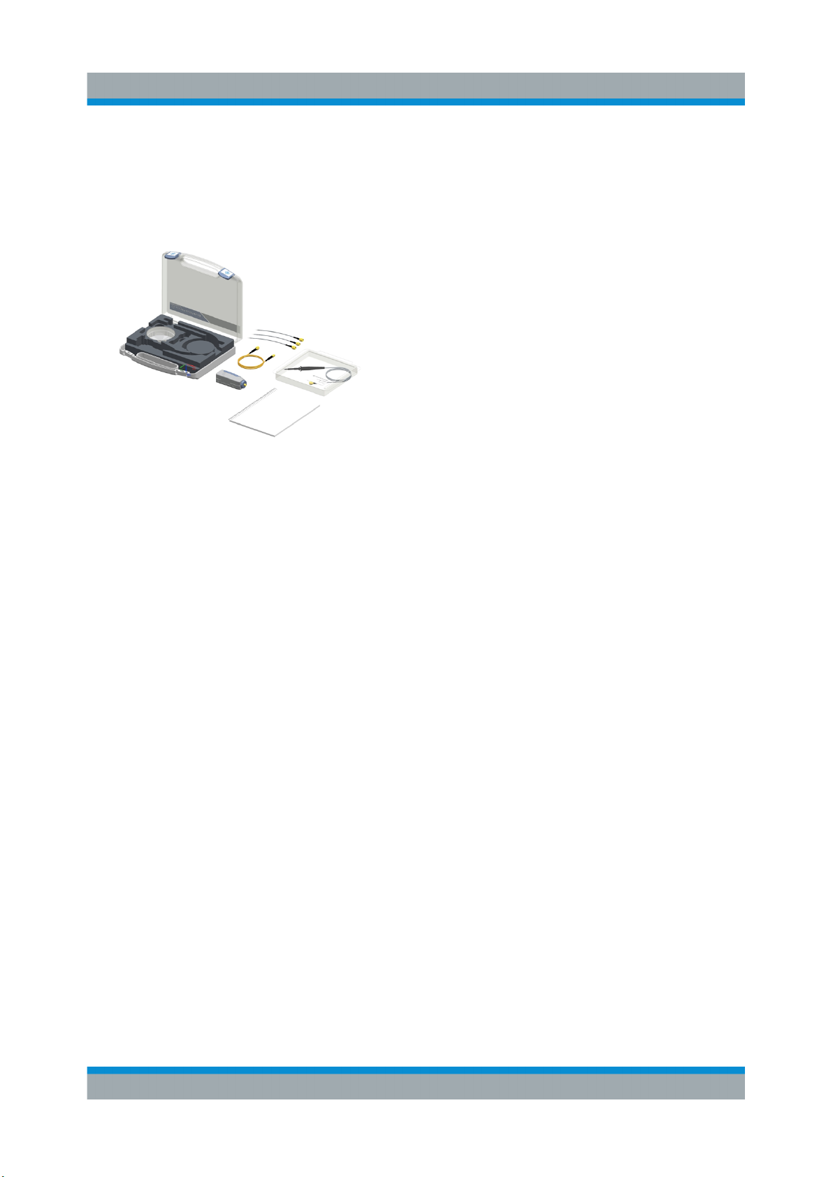
2.2 Unpacking
The carrying case contains the following items:
●
R&S RT-ZPR20/40 power-rail probe
●
Accessory container
●
Pigtail cables
●
User manual
●
R&S RT-ZPR20/40 data sheet
●
Calibration certificate
●
R&S RT-ZA25 power rail browser kit
●
Documented calibration values (if ordered)
Product Description
Unpacking
2.2.1 Inspecting the Contents
●
Inspect the package for damage.
Keep the package and the cushioning material until the contents have been
checked for completeness and the device has been tested.
If the packaging material shows any signs of stress, notify the carrier and your
Rohde & Schwarz service center. Keep the package and cushioning material
for inspection.
●
Inspect the probe.
If there is any damage or defect, or if the R&S RT-ZPR20/40 power-rail probe
does not operate properly, notify your Rohde & Schwarz service center.
●
Inspect the accessories.
If the contents are incomplete or damaged, notify your Rohde & Schwarz service center.
Accessories supplied with the device are listed in Chapter 2.3.2, "Supplied
Accessories", on page 10.
8User Manual 1800.5035.02 ─ 03
Page 9
R&S®RT-ZPR20 R&S®RT-ZPR40
Product Description
Description of the Probe
2.3 Description of the Probe
The probe consists of the active probe box with an Rohde & Schwarz probe interface to connect to the oscilloscope, and an SMA connector to connect to the DUT.
Use the SMA interface to connect the supplied solder-in and extension cables or
the power rail browser.
All available accessories are documented in the following chapters.
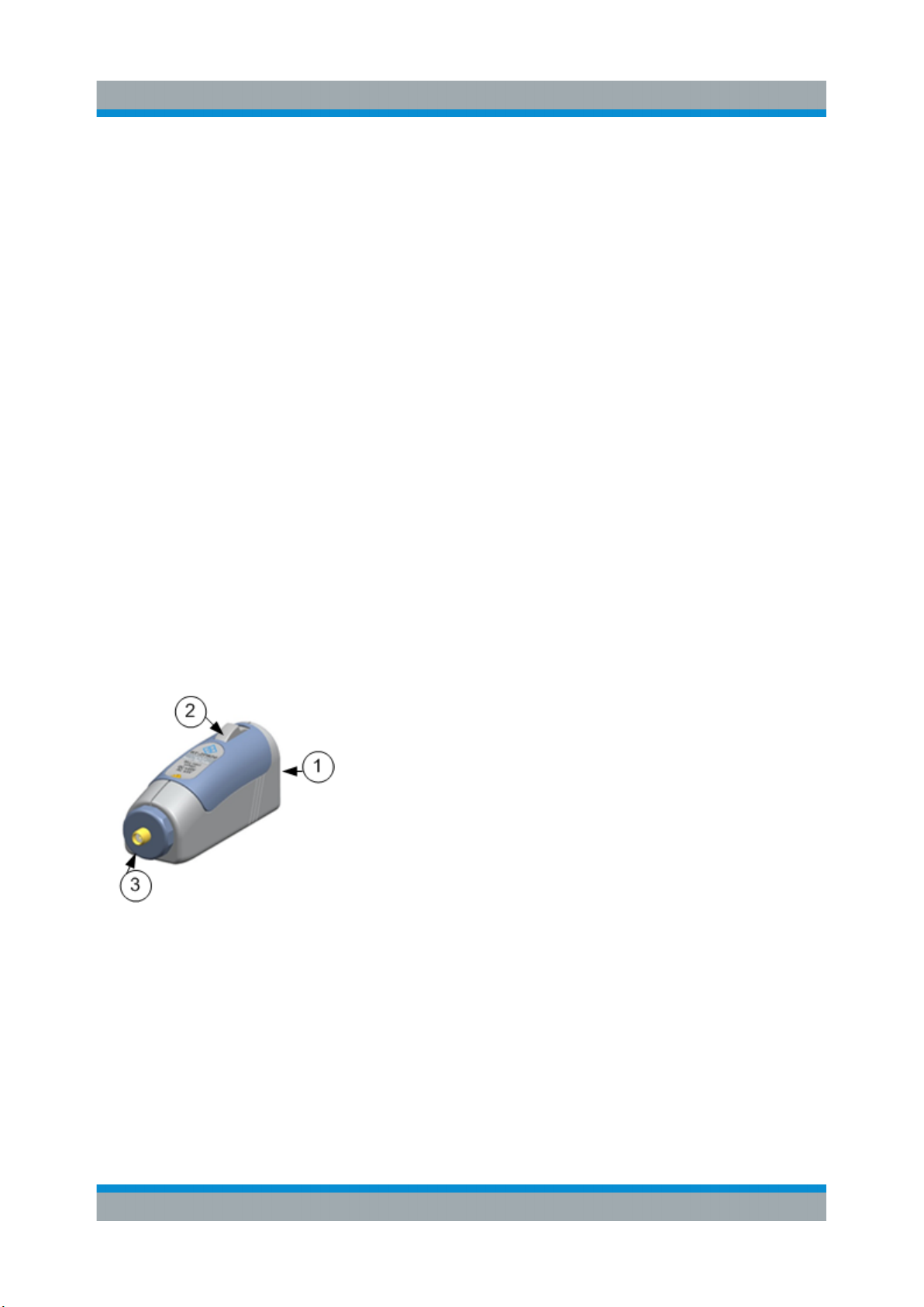
2.3.1 Probe Box
The probe box connects the probe to the oscilloscope via the Rohde & Schwarz
probe interface. The Rohde & Schwarz probe interface contains a male precision
7 mm (276 mil) BNC connector and six pogo pin connectors. This interface provides the required supply voltage and is also used for simultaneously transmitting
analog signals and digital data. All the analog voltages required by the probe are
generated in the probe box. This approach ensures you can operate future
probes on any base unit that features a Rohde & Schwarz probe interface. The
probe box provides an SMA connector to screw on different accessories suitable
for various measurement tasks.
(1) Rohde & Schwarz probe interface with
7 mm (276 mil) coaxial connector and 6 pogo
pins
(2) Release knob
(3) SMA connector
Connect the R&S RT-ZPR20/40 only to an instrument with Rohde & Schwarz
probe interface. Never connect it to a usual BNC jack. Although the 7 mm coaxial
connector looks like a standard BNC connector, it is constructed differently and
does not fit to the standard BNC jack. The interface of the R&S RT-ZPR20/40 can
withstand a higher frequency limit.
9User Manual 1800.5035.02 ─ 03
Page 10
R&S®RT-ZPR20 R&S®RT-ZPR40
Product Description
Description of the Probe
2.3.2 Supplied Accessories
Before you can use the probe for measurements, connect one of the accessories
to the SMA connector at the probe box.
Table 2-1 shows the accessories that are supplied with the R&S RT-ZPR20/40
power-rail probe.
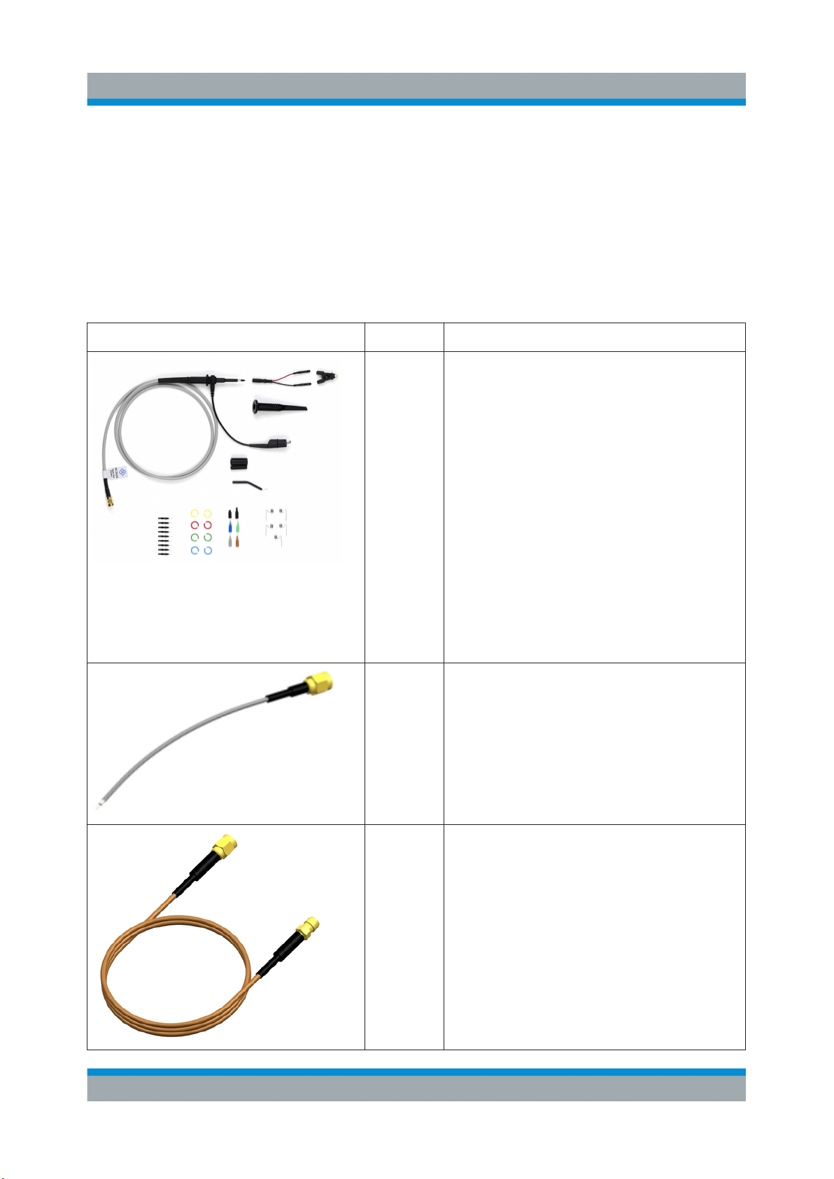
Table 2-1: Supplied accessories
Item Quantity Description
1
3 R&S RT-ZA26 pigtail cable, 15 cm
R&S RT-ZA25 power rail browser kit
includes:
●
Power rail browser
●
Ground lead with alligator clip
●
Ground spring (5)
●
IC cap (5)
●
Tip insulating cap
●
Tip (5)
●
Spring tip (5)
●
Sprung hook
●
Micro SMD clip
●
Dual adapter
●
Flexible ground lead with adapter
●
Coding rings (8)
●
Short tube
●
Long tube
1 SMA extension cable, 1 m (R&S RT-
ZPR20)
SMA extension cable low loss, 1 m
(R&S RT-ZPR40)
10User Manual 1800.5035.02 ─ 03
Page 11

R&S®RT-ZPR20 R&S®RT-ZPR40
Product Description
Description of the Probe
Item Quantity Description
1 Solder wire, lead free, 5 m
7 Adhesive pads
For a list of spare parts, see Chapter 6.6, "Spare Parts", on page 30.
2.3.3 Optional Accessories
If the delivered accessories do not meet individual customer requirements,
Rohde & Schwarz offers different accessory sets for sale. The order numbers are
provided in the data sheet.
Table 2-2: Optional accessories
Item Description
R&S RT-ZA9 probe box to N / USB adapter
The adapter connects the R&S RT-ZPR20/40 power-
rail probe to any other oscilloscope or any other measurement instrument (e.g. a network or spectrum analyzer).
Using the USB interface of the adapter, the probe can
be powered and controlled from any conventional PC.
Full software functionality is only provided by the supported base units (see data sheet).
11User Manual 1800.5035.02 ─ 03
Page 12

R&S®RT-ZPR20 R&S®RT-ZPR40
Item Description
R&S RT-ZA10 SMA adapter
SMA adapter with SMA (female) jack to BNC (male)
plug.
R&S RT-ZAP probe positioner
Use the R&S RT-ZAP probe positioner to position and
stabilize your probe.
Product Description
Description of the Probe
R&S RT-ZF20 power deskew fixture
The R&S RT-ZF20 power deskew fixture is a tool to
align the time delay (skew) of any combination of
Rohde & Schwarz voltage and current probes. The fixture can be used with any oscilloscope.
2.3.4 Service Accessories
To order accessories for servicing the probe, contact your Rohde & Schwarz service center. The following accessories are available:
12User Manual 1800.5035.02 ─ 03
Page 13

R&S®RT-ZPR20 R&S®RT-ZPR40
Product Description
Description of the Probe
Table 2-3: Service accessories
Item Description
R&S RT-ZK1 The service kit is used to calibrate the probe, to do perform-
ance tests, and for servicing. The service kit includes all
adapters and accessories to connect the probe to the
required measuring instruments.
R&S RT-ZPR20/40 Service Manual
The service manual contains a detailed description of the
performance test to verify the specifications, and other
important service procedures.
13User Manual 1800.5035.02 ─ 03
Page 14

R&S®RT-ZPR20 R&S®RT-ZPR40
Connecting the Probe to the Oscilloscope
Putting into Operation
3 Putting into Operation
The probe is designed for usage with oscilloscopes that have a Rohde & Schwarz
probe interface. Supported Rohde & Schwarz oscilloscopes are listed in the probe's data sheet.
Read and observe Chapter 1, "Safety Information", on page 5.
During usage, the probe slightly heats up. Warming is normal behavior and not a
sign of malfunction.
3.1 Connecting the Probe to the Oscilloscope
Connecting
1. If the extension cable is connected to the probe box, disconnect it.
To avoid damage to the device, connect the cable only to a grounded probe.
2. If your DUT is floating and not grounded, connect the DUT ground to the oscilloscope ground before connecting the probe to your DUT.
3. Connect the probe box (1) to the Rohde & Schwarz probe interface of the
base unit (2).
The probe snaps in when connected properly to the port.
4. Connect the extension cable to the probe box.
14User Manual 1800.5035.02 ─ 03
Page 15

R&S®RT-ZPR20 R&S®RT-ZPR40
Putting into Operation
Identification of the Probe
Figure 3-1: Connecting the probe to the Rohde & Schwarz oscilloscope
Disconnecting
1. Disconnect the accessories from the probe box before changing a probing
point, or before disconnecting the probe box from the oscilloscope.
2. To disconnect the probe:
a) Press and hold the release button (3).
b) Pull the probe box away from the oscilloscope.
3.2 Identification of the Probe
When the probe is connected to the oscilloscope, the oscilloscope recognizes the
probe and reads out the probe-specific parameters.
15User Manual 1800.5035.02 ─ 03
Page 16

R&S®RT-ZPR20 R&S®RT-ZPR40
Offset Compensation and Dynamic Range
The oscilloscope settings for attenuation and offset are automatically adjusted.
After the probe is connected to the oscilloscope and the settings are adjusted, the
waveform is shown for the channel to which the probe is connected.
The complete probe information is shown in the probe settings dialog. For more
information, refer to the user manual of your oscilloscope.
Putting into Operation
3.3 Offset Compensation and Dynamic Range
The dynamic range for the R&S RT-ZPR20/40 power rail probe determines the
maximum voltage swing that may occur between the input terminal and ground.
The dynamic range of the R&S RT-ZPR20/40 is ±0.850 V. If this range is exceeded, an unwanted signal clipping may occur.
The R&S RT-ZPR20/40 probe features a very comprehensive offset compensation function. The compensation of DC components directly inside the probe box
even in front of the active probe amplifier is possible with an extremely wide compensation range of ±60 V. This function is useful when measuring AC signals with
a high superimposed DC component.
► Adjust the offset at the oscilloscope. You can use the vertical [Position] knob,
or the offset setting in the channel or probe setup.
For details, refer to the user manual of your oscilloscope.
16User Manual 1800.5035.02 ─ 03
Page 17

R&S®RT-ZPR20 R&S®RT-ZPR40
Putting into Operation
AC Coupling Mode
Figure 3-2: Offset compensation voltage and dynamic range
3.4 AC Coupling Mode
The R&S RT-ZPR20/40 power-rail probe features an internal AC coupling mode
with a low frequency cutoff at 10 Hz to block DC components of the input signal.
The AC coupling is set inside the probe, the full bandwidth of the probe remains.
"AC coupling" is part of the probe settings of the channel to which the probe is
connected. For more details, see the oscilloscope's user manual.
17User Manual 1800.5035.02 ─ 03
Page 18

R&S®RT-ZPR20 R&S®RT-ZPR40
Putting into Operation
R&S ProbeMeter
3.5 R&S ProbeMeter
The R&S ProbeMeter is an integrated voltmeter that measures DC voltages with
higher precision compared to the oscilloscope's DC accuracy. The DC measurement is performed continuously and in parallel to the time domain measurement
of the oscilloscope.
High-precision measurements are achieved by immediate digitization of the measured DC voltage at the probe tip.
When the R&S ProbeMeter is active, the measured values are displayed on the
oscilloscope. The R&S ProbeMeter state is part of the probe settings of the channel to which the probe is connected. For details, refer to the user manual of the
Rohde & Schwarz oscilloscope.
Advantages of the R&S ProbeMeter:
●
Measures DC voltages of different levels, no need to adjust the measurement
range of the oscilloscope.
●
True DC measurement (integration time > 100 ms), not mathematical average
of displayed waveform.
●
High measurement accuracy and low temperature sensitivity.
●
Simple means of setting the oscilloscope's trigger level and vertical scaling if a
waveform is not visible.
●
Independent of oscilloscope settings for offset, position, vertical scale, horizontal scale, and trigger.
●
Measurement range ±60 V
18User Manual 1800.5035.02 ─ 03
Page 19

R&S®RT-ZPR20 R&S®RT-ZPR40
Connecting the Probe to the DUT
R&S RT-ZA25 Power Rail Browser Kit
4 Connecting the Probe to the DUT
This chapter describes how to connect the probe to the DUT using different
accessories supplied for the R&S RT-ZPR20/40 probe. The various accessories
are described and their use is explained.
The recommended configurations are designed for best probe performance in
various probing situations. Thus, you can measure quickly and with confidence in
the performance and signal fidelity. Use the recommended connection configurations for accurate oscilloscope measurements with known performance levels.
Using solder-in accessories
Some solder-in accessories are very fine and sensitive. Stabilize the probe using
appropriate means (e.g. adhesive pads, probe positioner) in order to protect the
solder joint from excessive mechanical stress.
Before soldering or unsoldering the pigtail cable, disconnect the pigtail cable from
the probe box.
Observe operating temperature range
The R&S RT-ZPR20/40 probe box has a specified operating temperature range
from 0 °C to 40 °C, whereas the pigtail and extension cables can withstand wider
temperature ranges (see Chapter 4.2, "R&S RT-ZA26 Pigtail Cable",
on page 21). Do not subject the probe box to temperatures outside of its operating range.
4.1 R&S RT-ZA25 Power Rail Browser Kit
The R&S RT-ZA25 power rail browser kit allows handheld probing with maximum
convenience at the DUT and is sufficient up to 350 MHz bandwidth.
19User Manual 1800.5035.02 ─ 03
Page 20

R&S®RT-ZPR20 R&S®RT-ZPR40
Connecting the Probe to the DUT
R&S RT-ZA25 Power Rail Browser Kit
Risk of injuries
Always observe the maximum rating of ±60 V DC, 30 V AC (RMS), or
±42 V AC (peak). The R&S RT-ZA25 is not equipped with a protective
impedance and must not be used to measure higher voltages.
The included browser pins are exceptionally sharp and must be handled
with extreme care. To prevent injuries, always use tweezers when inserting
or removing pins.
To avoid damaging the browser parts, use them carefully:
●
Do not apply a side load to the browser.
●
Do not apply too much force when browsing. The weight of the probe in your
hand is sufficient.
●
Always remove the browser from the DUT before disconnecting the probe
from the oscilloscope.
Connect the R&S RT-ZA25 power rail browser
to the SMA interface of the R&S RT-ZPR20/40
probe box. You can use the browser in the
same way as conventional passive probes.
Bandwidth: >350 MHz
Length: 1 m
Temperature range: 0 °C to +40 °C
For highest bandwidth and signal integrity, use
the ground spring and spring loaded or rigid
signal tips.
20User Manual 1800.5035.02 ─ 03
Page 21

R&S®RT-ZPR20 R&S®RT-ZPR40
Connecting the Probe to the DUT
R&S RT-ZA26 Pigtail Cable
For convenient probing and medium bandwidth, use the flexible ground lead with
adapter.
Use the long-distance ground lead with alligator clip to contact far away ground points. Due
to the larger loop inductance, bandwidth is
decreased.
Use the dual adapter to plug onto pin strips or
to connect the micro SMD clip.
Use the micro SMD clip to connect surface
mount devices, e.g. 0805, 0402 capacitors.
4.2 R&S RT-ZA26 Pigtail Cable
The R&S RT-ZA26 pigtail cable is a semi-permanent solder-in connection that
supports the full bandwidth of the probe.
Before soldering or unsoldering the pigtail cable, always disconnect the cable
from the probe box.
21User Manual 1800.5035.02 ─ 03
Page 22

R&S®RT-ZPR20 R&S®RT-ZPR40
Connecting the Probe to the DUT
R&S RT-ZA26 Pigtail Cable
The R&S RT-ZA26 pigtail cable is well suited
for creating solid contact with test points that
are hard to reach (e.g. IC pins, SMT parts).
Bandwidth:
• >2 GHz (R&S RT-ZPR20)
• >3.5 GHz (R&S RT-ZPR40)
Length: 15 cm (1.15 m with SMA extension
cable)
Temperature range: -55 °C to +125 °C
Do not connect the R&S RT-ZA26 pigtail cable
directly to the probe box.
Connect the R&S RT-ZA26 pigtail cable to the
SMA extension cable. Connect the other end
of the SMA cable to the R&S RT-ZPR20/40
probe box.
For measurements, solder the center conductor to the signal and the outer shield conductor
to the ground.
22User Manual 1800.5035.02 ─ 03
Page 23

R&S®RT-ZPR20 R&S®RT-ZPR40
Connecting the Probe to the DUT
SMA Extension Cable
Risk of damaging the probe due to excess heat
When using the R&S RT-ZA26 pigtail cable, do not expose the R&S RTZPR20/40 probe box to temperatures outside the valid range (see "Observe
operating temperature range" on page 19). Excess heat can damage the
probe.
4.3 SMA Extension Cable
The supplied SMA extension cable is a semi-permanent screw connection that
supports the full bandwidth of the probe.
The SMA extension cable is well suited for
connections to existing SMA (m) ports at your
test circuit. Due to the design of the coaxial
interface, ground loop impedance is minimized. Thus, this connection provides highest
signal integrity. Connection to other coaxial
interfaces like SMA (f), BNC, SMP, SMB is
possible using the appropriate adapter.
Coaxial adapters are not part of the R&S RTZPR20/40 accessories set.
Bandwidth:
• >2 GHz (R&S RT-ZPR20)
• >4 GHz (R&S RT-ZPR40)
Length: 1 m
Temperature range:
• -55 °C to +125 °C (SMA extension cable)
• -45 °C to +85 °C (SMA extension cable low
loss)
23User Manual 1800.5035.02 ─ 03
Page 24

R&S®RT-ZPR20 R&S®RT-ZPR40
Measurement Principles
5 Measurement Principles
The R&S RT-ZPR20/40 power-rail probe provides an electrical connection
between the DUT and the oscilloscope. The probe transfers the voltage of the
electrical signal tapped off the DUT to the oscilloscope, where it is displayed
graphically.
Although a probe has a wide variety of specifications, these specifications can be
grouped into two classes of basic requirements:
●
High signal integrity of the transferred signal: With an ideal probe, the output
signal that is transferred to the base unit would be identical to the input signal
between the probe tips. Furthermore, signal integrity would be extremely high.
Every real probe, however, transfers the input signal in altered form. A good
probe causes only minimum alterations. How the probe can fulfill this requirement is mainly determined by its bandwidth.
●
Low loading of the input signal: Every probe is a load for the signal to be measured. This means that the signal to be measured changes as soon as the
probe is connected. A good probe should cause only a minimum change to
the signal, so that the function of the DUT is not adversely affected. How well
the probe can fulfill this requirement is mainly determined by its input impedance.
The parameters of a probe are usually specified for a minimized connection
between the probe and the DUT. With longer connections, the connection inductance has a significant effect on the measurement. The high-frequency behavior
of the power rail probe is typically characterized with 0 Ω source impedance. Fig-
ure 5-1 shows the R&S RT-ZPR20/40 power-rail probe that is connected to the
DUT.
Figure 5-1: Equivalent circuit model of the R&S RT-ZPR20/40 probe
24User Manual 1800.5035.02 ─ 03
Page 25

R&S®RT-ZPR20 R&S®RT-ZPR40
Abbreviation Description
Measurement Principles
Step Response
V
S
V
in
Voltage at the test point without probe connected
Voltage at the test point with probe connected, corresponds to the input voltage of the probe
R
S
R
in
R
RF
C
in
L
con
Source impedance of the DUT
DC input resistance of the probe
RF input resistance
Coupling capacitance
Parasitic inductance of the ground connection
5.1 Step Response
Figure 5-2 shows the step response of the R&S RT-ZPR20/40 with an ideal input
step.
Figure 5-2: Example of the step response of the R&S RT-ZPR20/40 probe with the sup-
plied SMA extension cable
25User Manual 1800.5035.02 ─ 03
Page 26

R&S®RT-ZPR20 R&S®RT-ZPR40
Measurement Principles
Frequency Response
5.2 Frequency Response
The R&S RT-ZPR20/40 probe is a dedicated power rail probe, designed for measurements at low impedance voltage sources such as DC power supplies with an
output impedance < 1 Ohm.
A DUT with an output impedance (RS) higher than 1 Ohm leads to a mismatch
between DC gain and AC gain. The mismatch causes a step at 1 MHz and thus
non-flat frequency response.
In the time domain, a non-ideal frequency response occurs as a step which only
gradually approaches the final DC value.
Figure 5-3: Example of the frequency response of the R&S RT-ZPR40 probe with SMA
extension cable for different source impedances
26User Manual 1800.5035.02 ─ 03
Page 27

R&S®RT-ZPR20 R&S®RT-ZPR40
Measurement Principles
Input Impedance
5.3 Input Impedance
The input signal loading caused by the probe is determined by its input impedance Zin. Figure 5-1 illustrates an equivalent circuit model. The resulting input
impedance versus frequency is indicated in Figure 5-4.
Figure 5-4: Example of the input impedance of the R&S RT-ZPR20/40 probe with SMA
extension cable as a function of frequency
27User Manual 1800.5035.02 ─ 03
Page 28

R&S®RT-ZPR20 R&S®RT-ZPR40
Maintenance and Service
Contacting Customer Support
6 Maintenance and Service
Like all Rohde & Schwarz products, Rohde & Schwarz probes and adapters are
of high quality and require only minimum service and repair. However, if service
or calibration is needed, contact your Rohde & Schwarz service center. Return a
defective product to the Rohde & Schwarz service center for diagnosis and
exchange.
6.1 Cleaning
1. Clean the outside of the product using a soft cloth moistened with either distilled water or isopropyl alcohol. Keep in mind that the casing is not waterproof.
Note: Do not use cleaning agents. Solvents (thinners, acetone), acids and
bases can damage the labeling or plastic parts.
2. Dry the product completely before using it.
6.2 Contacting Customer Support
Technical support – where and when you need it
For quick, expert help with any Rohde & Schwarz equipment, contact one of our
Customer Support Centers. A team of highly qualified engineers provides telephone support and works with you to find a solution to your query on any aspect
of the operation, programming or applications of Rohde & Schwarz equipment.
Up-to-date information and upgrades
To keep your instrument up-to-date and to be informed about new application
notes related to your instrument, please send an e-mail to the Customer Support
Center stating your instrument and your wish. We will make sure that you get the
right information.
28User Manual 1800.5035.02 ─ 03
Page 29

R&S®RT-ZPR20 R&S®RT-ZPR40
Europe, Africa, Middle East
Phone +49 89 4129 12345
customersupport@rohde-schwarz.com
North America
Phone 1-888-TEST-RSA (1-888-837-8772)
customer.support@rsa.rohde-schwarz.com
Latin America
Phone +1-410-910-7988
customersupport.la@rohde-schwarz.com
Asia/Pacific
Maintenance and Service
Returning for Servicing
Phone +65 65 13 04 88
customersupport.asia@rohde-schwarz.com
China
Phone +86-800-810-8228 / +86-400-650-5896
customersupport.china@rohde-schwarz.com
6.3 Returning for Servicing
Use the original packaging to return your R&S RT-ZPR20/40 to your
Rohde & Schwarz service center. A list of all service centers is available on:
www.services.rohde-schwarz.com
If you cannot use the original packaging, consider the following:
1. Use a sufficiently sized box.
2. Protect the product from damage and moisture (e.g. with bubble wrap).
3. Use some kind of protective material (e.g. crumpled newspaper) to stabilize
the product inside the box.
29User Manual 1800.5035.02 ─ 03
Page 30

R&S®RT-ZPR20 R&S®RT-ZPR40
4. Seal the box with tape.
5. Address the package to your nearest Rohde & Schwarz service center.
Maintenance and Service
Spare Parts
6.4 Calibration Interval
The recommended calibration interval for R&S RT-ZPR20/40 power-rail probe is
two years. For servicing, send the probe to your nearest Rohde & Schwarz service center (see Chapter 6.3, "Returning for Servicing", on page 29).
6.5 Discarding the Product
Handle and dispose the product in accordance with local regulations.
6.6 Spare Parts
The following accessories can be ordered at the Rohde & Schwarz service center. Use the order numbers provided in the following table.
Table 6-1: Accessories spare parts
Pos Item Description Part Number
1 Adhesive pads 1800.4268.00
2 Solder wire, lead free, 5 m 1800.4097.00
30User Manual 1800.5035.02 ─ 03
Page 31

R&S®RT-ZPR20 R&S®RT-ZPR40
Maintenance and Service
Spare Parts
Pos Item Description Part Number
3 SMA extension cable, 1 m
For R&S RT-ZPR20
4 SMA extension cable low loss, 1
m
For R&S RT-ZPR40
Spare parts for the R&S RT-ZA25 power rail browser kit
1800.5241.00
1337.9081.00
5 Ground lead with alligator clip 1800.5335.00
6 Dual adapter 1800.5341.00
7 Micro SMD clip 1800.5358.00
8 Flexible ground lead with
adapter
1800.5364.00
The following accessories can be ordered from Rohde & Schwarz. The order
numbers are listed in the data sheet.
●
R&S RT-ZA25 power rail browser kit
●
R&S RT-ZA26 pigtail cable, 15 cm
31User Manual 1800.5035.02 ─ 03
Page 32

R&S®RT-ZPR20 R&S®RT-ZPR40
Table 6-2: Parts for ESD prevention
Pos. Item Material number
1 ESD wrist strap 0008.9959.00
2 ESD grounding cable 1043.4962.00
Maintenance and Service
Spare Parts
32User Manual 1800.5035.02 ─ 03
 Loading...