

Page 1
®
R&S
RT‑ZM
Modular Probe System
User Manual
(>COL2)
1419312802
Version 04
User Manual
Page 2

This manual describes the following R&S®RT-ZM models:
●
R&S®RT-ZM15 (1800.4700K02)
●
R&S®RT-ZM30 (1419.3005K02)
●
R&S®RT-ZM60 (1419.3105K02)
●
R&S®RT-ZM90 (1419.3205K02)
●
R&S®RT-ZM130 (1800.4500K02)
●
R&S®RT-ZM160 (1800.4600K02)
© 2019 Rohde & Schwarz GmbH & Co. KG
Mühldorfstr. 15, 81671 München, Germany
Phone: +49 89 41 29 - 0
Fax: +49 89 41 29 12 164
Email: info@rohde-schwarz.com
Internet: www.rohde-schwarz.com
Subject to change – Data without tolerance limits is not binding.
R&S® is a registered trademark of Rohde & Schwarz GmbH & Co. KG.
Trade names are trademarks of the owners.
1419.3128.02 | Version 04 | R&S®RT‑ZM
Throughout this manual, products from Rohde & Schwarz are indicated without the ® symbol and without
product type numbers, e.g. R&S®RT-ZM15/30/60/90/130/160 is indicated as R&S RT-ZM.
Page 3

R&S®RT‑ZM
Contents
Contents
1 Product Description.............................................................. 5
1.1 Key Features and Key Characteristics............................................... 5
1.1.1 Key Characteristics................................................................................. 5
1.1.2 Key Features...........................................................................................6
1.2 Unpacking..............................................................................................7
1.2.1 Inspecting the Contents.......................................................................... 7
1.3 Description of the Probe...................................................................... 8
1.3.1 Probe Amplifier....................................................................................... 8
1.3.2 Probe Box............................................................................................... 9
1.3.3 Probe Tip Modules..................................................................................9
1.3.4 Accessories and Items..........................................................................10
2 Putting into Operation.........................................................13
2.1 Connecting the Probe to the Oscilloscope...................................... 14
2.2 Identification of the Probe..................................................................15
2.3 MultiMode............................................................................................ 15
2.4 Dynamic Range and Operating Voltage Window............................. 17
2.5 Micro Button........................................................................................18
2.6 Offset Compensation..........................................................................18
2.6.1 Differential Offset.................................................................................. 20
2.6.2 Common Mode Offset...........................................................................20
2.6.3 Positive Input Single-Ended Offset....................................................... 21
2.6.4 Negative Input Single-Ended Offset......................................................22
2.7 R&S ProbeMeter..................................................................................23
3 Connecting the Probe to the DUT...................................... 24
3.1 R&S RT-ZMA10 Tip Cable Solder-In.................................................. 25
3User Manual 1419.3128.02 ─ 04
Page 4

R&S®RT‑ZM
3.2 R&S RT-ZMA12 Tip Cable Square Pin...............................................27
3.3 R&S RT-ZMA14 Tip Cable Flex Connect........................................... 28
3.4 R&S RT-ZMA15 Tip Cable Quick Connect........................................ 29
3.5 R&S RT-ZMA30 Browser Module.......................................................30
3.6 R&S RT-ZMA40 SMA Module............................................................. 32
3.7 R&S RT-ZMA50 Extreme Temperature Kit........................................ 33
Contents
4 Maintenance and Service....................................................35
4.1 Cleaning...............................................................................................35
4.2 Contacting Customer Support...........................................................35
4.3 Returning for Servicing...................................................................... 36
4.4 Calibration Interval............................................................................. 37
4.5 Spare Parts ......................................................................................... 37
4User Manual 1419.3128.02 ─ 04
Page 5
R&S®RT‑ZM
Key Features and Key Characteristics
Product Description
1 Product Description
1.1 Key Features and Key Characteristics
The R&S RT-ZM is a modular probe consisting of a probe amplifier and various
probe tip modules for different applications.
The R&S RT-ZM probe family features the MultiMode function which allows you
to switch between single-ended, differential and common mode measurements
without reconnecting or re-soldering the probe.
With different tip modules and tip cables, the R&S RT-ZM probe can be connected to a wide variety of devices under test (DUT) and is suitable for various measurement tasks.
Provided with special features such as the R&S ProbeMeter and the micro button,
the R&S RT-ZM is designed to meet tomorrow's challenges in probing.
The probe is equipped with theRohde & Schwarz probe interface. It can be connected to any Rohde & Schwarz instrument that is compatible with this interface.
When connected to the front panel, the probe is controlled by the oscilloscope's
software. Supported oscilloscopes are listed in the data sheet.
1.1.1 Key Characteristics
The key characteristics of the probe are the following:
MultiMode feature for differential, common mode and single-ended measurements
Two different probe gain settings with 10:1 and 2:1 attenuation to achieve low system noise
Bandwidth DC to 1.5 GHz (R&S RT-ZM15)
DC to 3 GHz (R&S RT-ZM30)
DC to 6 GHz (R&S RT-ZM60)
DC to 9 GHz (R&S RT-ZM90)
DC to 13 GHz (R&S RT-ZM130)
DC to 16 GHz (R&S RT-ZM160)
Dynamic range ±2.5 V (10:1 attenuation)
±0.5 V (2:1 attenuation)
5User Manual 1419.3128.02 ─ 04
Page 6
R&S®RT‑ZM
Product Description
Key Features and Key Characteristics
Operating voltage window
(each pin to GND)
Maximum non-destructive input voltage ±30 V
Input resistance Differential: 400 kΩ
R&S ProbeMeter, measurement error <0.2 %
R&S ProbeMeter, dynamic range ±7 V
Offset capability ±16 V for compensating single-ended, differential and
Low zero and gain errors throughout the entire temperature range for all measurement modes
Micro button
Rohde & Schwarz probe interface
±7.0 V with ±16 V offset capability, DC to 100 kHz
±5.0 V with ±16 V offset capability, > 100 kHz
Single-ended: 200 kΩ
common mode DC offsets
1.1.2 Key Features
Micro button
The micro button at the probe head can remotely control different functions on the
base unit. The assigned function is configured via the base unit.
For details, see Chapter 2.5, "Micro Button", on page 18.
R&S ProbeMeter
The R&S ProbeMeter measures the DC voltage of the input signal directly at the
probe tip. It provides a continuous high-precision DC voltage measurement that is
independent of the settings of the oscilloscope and runs in parallel to the time
domain measurement. If activated on the base unit, the measured value is displayed on the screen of the Rohde & Schwarz oscilloscope.
The R&S ProbeMeter simultaneously measures both differential and common
mode DC voltages.
For details, see Chapter 2.7, "R&S ProbeMeter", on page 23.
Probe DC correction
The probe amplifier includes an integrated data memory with individually determined DC correction parameters (e.g. gain, offset). These correction parameters
are read out and processed by the Rohde & Schwarz oscilloscope. As a result,
6User Manual 1419.3128.02 ─ 04
Page 7
R&S®RT‑ZM
Product Description
Unpacking
the probe offers a very high degree of DC accuracy so that additional calibration
procedures are not required.
Probe frequency correction
The R&S RT-ZM probe amplifier includes an integrated data memory with individually measured S-parameters. These correction parameters are read out and processed by the Rohde & Schwarz oscilloscope. This leads to a more accurate
probe frequency response and an enhanced measurement accuracy.
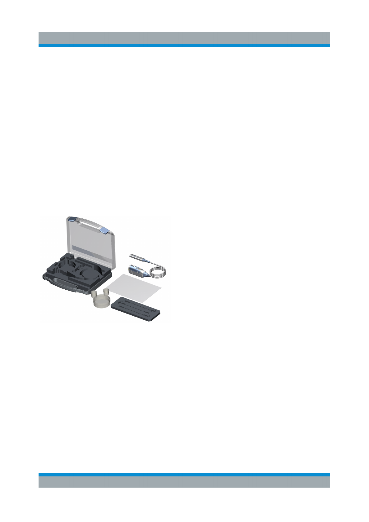
1.2 Unpacking
The carrying case contains the following items:
●
R&S RT-ZM modular probe
●
Carrying case
●
Accessory boxes
●
User manual
●
R&S RT-ZM data sheet
●
Calibration certificate
●
Documentation of calibration values (if
ordered)
●
Foam inlay for tip cables
If R&S RT-ZMA tip modules were ordered, they come in a separate packaging
and can be inserted into the foam inlay.
1.2.1 Inspecting the Contents
●
Inspect the package for damage.
Keep the package and the cushioning material until the contents have been
checked for completeness and the device has been tested.
If the packaging material shows any signs of stress, notify the carrier and your
Rohde & Schwarz service center. Keep the package and cushioning material
for inspection.
●
Inspect the probe.
7User Manual 1419.3128.02 ─ 04
Page 8
R&S®RT‑ZM
If there is any damage or defect, or if the R&S RT-ZM modular probe does not
operate properly, notify your Rohde & Schwarz service center.
●
Inspect the accessories.
If the contents are incomplete or damaged, notify your Rohde & Schwarz service center.
Product Description
Description of the Probe
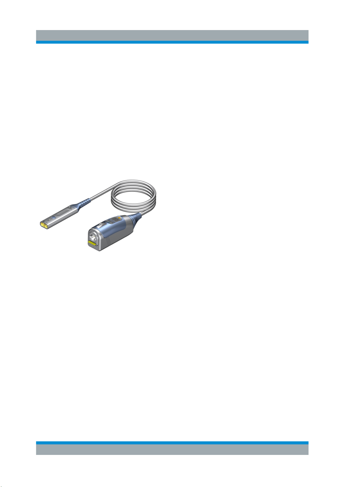
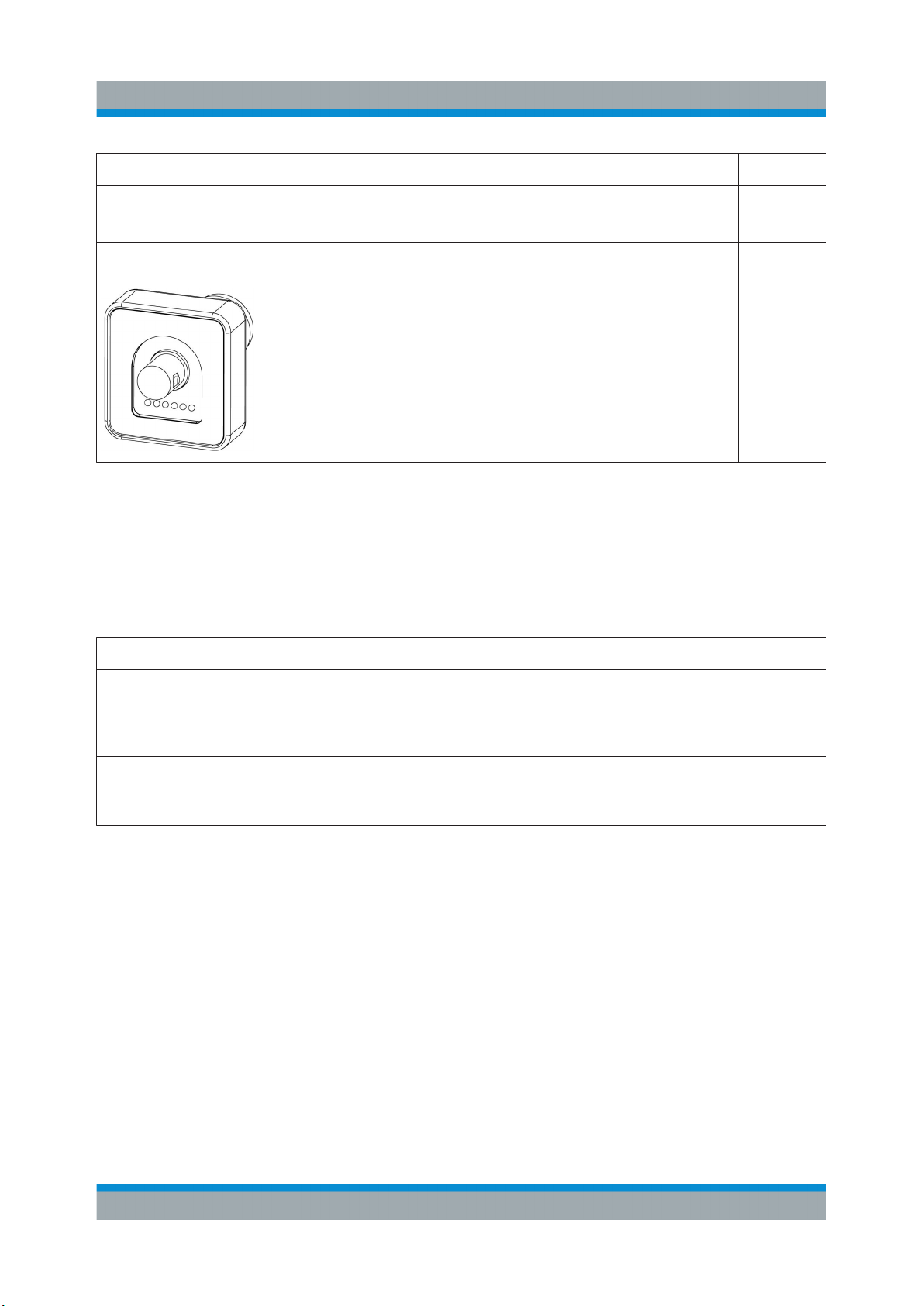
1.3 Description of the Probe
The probe consists of the active probe amplifier, the probe box for connection to
the oscilloscope, the probe cable and various probe tip modules.
Figure 1-1: R&S RT-ZM probe consisting of probe amplifier and probe box
1.3.1 Probe Amplifier
The probe amplifier is designed for easy handling and high performance measurements. The R&S RT-ZM probe amplifier is designed for use with the R&S RTZMA probe tip modules.
See also: Chapter 3, "Connecting the Probe to the DUT", on page 24.
8User Manual 1419.3128.02 ─ 04
Page 9
R&S®RT‑ZM
Product Description
Description of the Probe
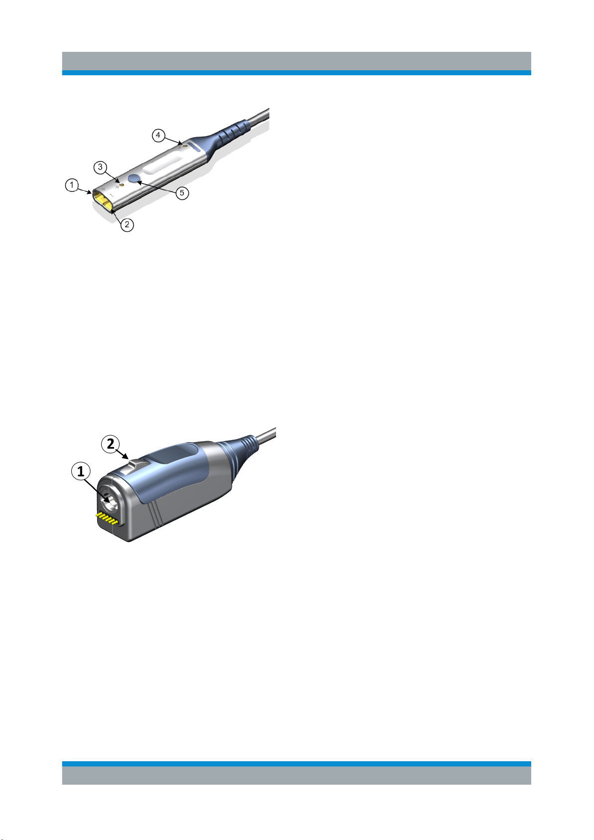
(1) Positive coaxial input
(2) Negative coaxial input
(3) Ground socket
(4) Termination voltage socket
(5) Micro button
Signal and Termination voltage sockets are
compatible with 0.64 mm (25 mil) square pins
and 0.6 mm to 0.8 mm (24 mil to 35mil) round
pins.
1.3.2 Probe Box
The probe box connects the probe and the oscilloscope via the Rohde & Schwarz
probe interface. The Rohde & Schwarz probe interface contains a male precision
7 mm (276 mil) BNC connector and six pogo pin connectors. This interface provides the required supply voltage and is also used to transmit analog signals and
digital data simultaneously. All the analog voltages required by the probe are generated in the probe box. This approach ensures that it will be possible to operate
future probes on any base unit that features a Rohde & Schwarz probe interface.
(1) Rohde & Schwarz probe interface with
7 mm (276 mil) coaxial connector and 6 pogo
pins
(2) Release knob
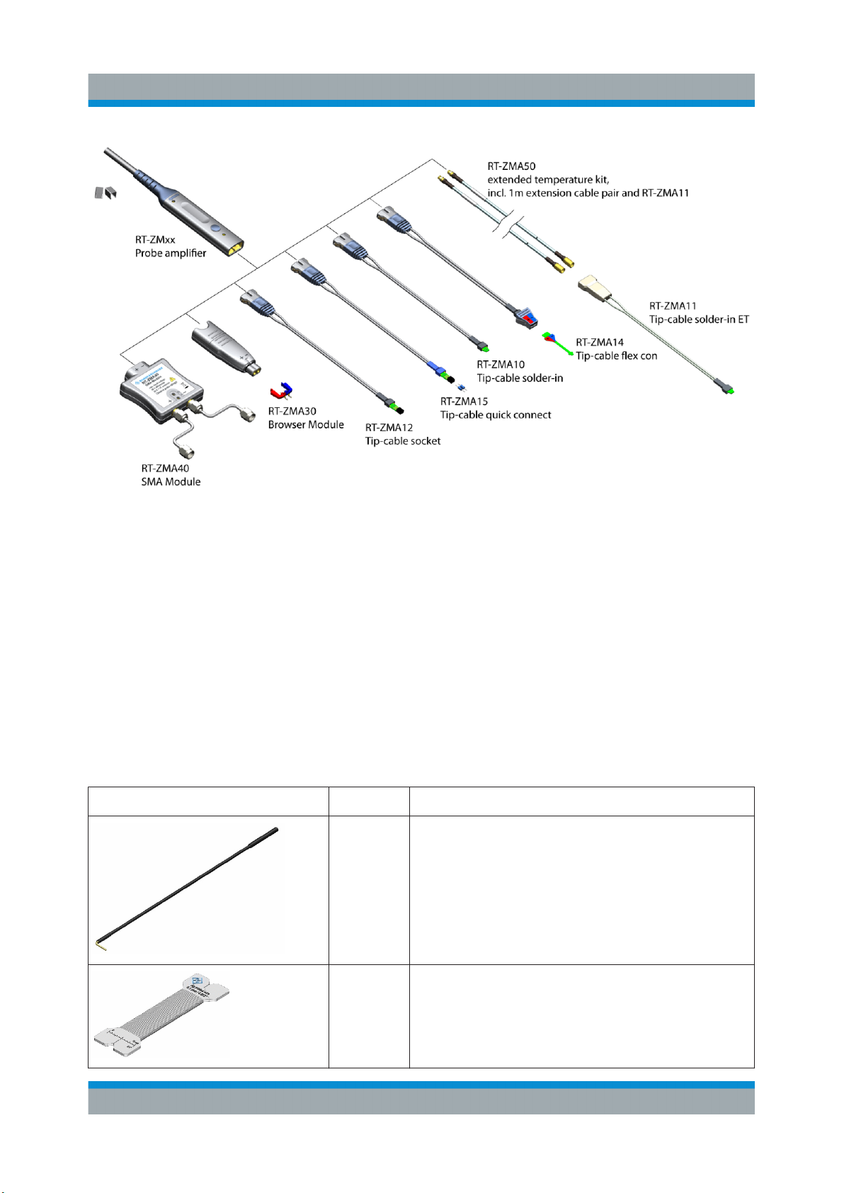
1.3.3 Probe Tip Modules
To use the probe for measurements, select the appropriate probe tip module and
connect it to the probe amplifier.
Figure 1-2 shows all probe tip modules are available for the R&S RT-ZM probe.
The usage of probe tip modules is described in Chapter 3, "Connecting the Probe
to the DUT", on page 24.
If you need more probe tip modules, you can order them at Rohde & Schwarz.
The order numbers are provided in the data sheet.
9User Manual 1419.3128.02 ─ 04
Page 10
R&S®RT‑ZM
Product Description
Description of the Probe
Figure 1-2: R&S RT-ZM probing system compatibility chart
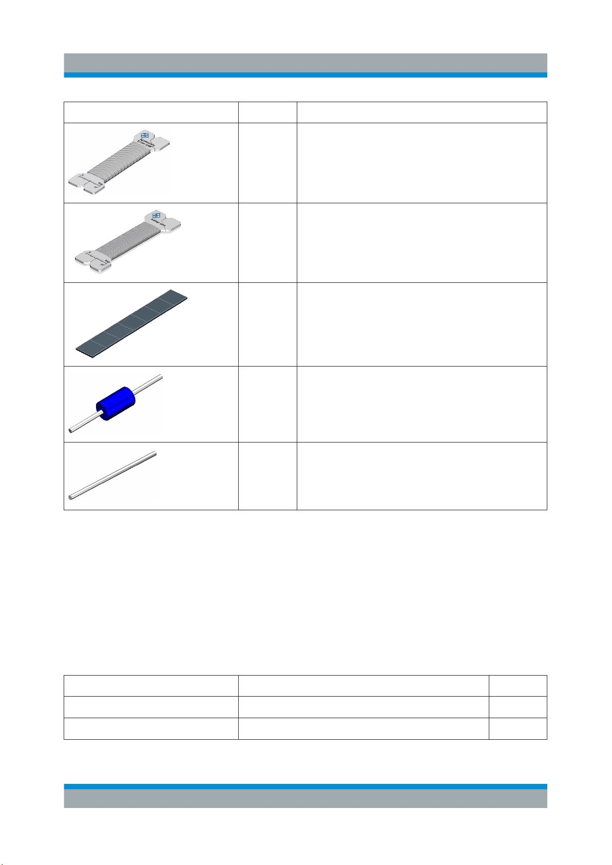
1.3.4 Accessories and Items
1.3.4.1 Accessories Supplied
Table 1-1 shows the accessories that are supplied with the R&S RT-ZM modular
probe.
Table 1-1: Accessories supplied
Item Quantity Description
1 Lead, 15 cm / 5.9 in
1 Solder wire 0.1mm, Ag plated, 10 m
10User Manual 1419.3128.02 ─ 04
Page 11
R&S®RT‑ZM
Item Quantity Description
1 Solder wire 0.2mm, Ag plated, 10 m
1 Solder wire, lead free, 5 m
7 Adhesive pads
Product Description
Description of the Probe
20 Solder in resistor (270 Ω) for R&S RT-ZMA15
20 Solder lead for R&S RT-ZMA12/15
For a list of spare parts, see Chapter 4.5, "Spare Parts ", on page 37.
1.3.4.2 Optional Accessories
If the delivered accessories do not meet individual customer requirements,
Rohde & Schwarz offers different accessory sets for sale. The order numbers are
provided in the data sheet.
Table 1-2: Optional accessories
Accessory set Items Quantity
R&S RT-ZA4 mini clips Mini clip 10
R&S RT-ZA5 micro clips Micro clip 4
11User Manual 1419.3128.02 ─ 04
Page 12
R&S®RT‑ZM
Product Description
Description of the Probe
Accessory set Items Quantity
R&S RT-ZA6 lead set Lead, 6 cm / 2.4 in
Lead, 15 cm / 5.9 in
R&S RT-ZA9 probe box to
N/USB adapter
The adapter connects the R&S RT-ZM modular
probe to any other oscilloscope or any other
measurement instrument (e.g. a network or
spectrum analyzer).
Using the USB interface of the adapter, the
probe can be powered and controlled from any
conventional PC. However, full software functionality is only provided by the supported oscilloscopes (see data sheet).
5
5
1
1.3.4.3 Service Accessories
To order accessories for servicing the probe, contact your Rohde & Schwarz service center. The following accessories are available:
Table 1-3: Service accessories
Item Description
R&S RT-ZK3 The service kit is used to calibrate the probe, to do perform-
ance tests, and for servicing. The service kit includes all
adapters and accessories to connect the probe to the
required measuring instruments.
R&S RT-ZM Service Manual The service manual contains a detailed description of the
performance test to verify the specifications, and other
important service procedures.
12User Manual 1419.3128.02 ─ 04
Page 13

R&S®RT‑ZM
Putting into Operation
2 Putting into Operation
The probe is designed for usage with oscilloscopes that have a Rohde & Schwarz
probe interface. Supported Rohde & Schwarz oscilloscopes are listed in the probe's data sheet.
Read and observe the printed "Basic Safety Instructions" that are delivered with
the probe. Also, read and observe the safety instructions of the oscilloscope the
probe is connected to.
Maximum non-destructive input voltage
The maximum non-destructive input voltage is ±30 V. A higher input voltage
can destroy the probe.
Risk of device damage
The R&S RT-ZM can withstand a moderate amount of physical and electrical stress. To avoid damage, treat the probe with care:
●
Do not exceed the specified voltage limits.
●
Connect the R&S RT-ZM only to an instrument with Rohde & Schwarz
probe interface. Never connect it to a usual BNC jack. Although the
7 mm coaxial connector looks like a standard BNC connector, it is constructed differently and does not fit to the standard BNC jack. The interface of the R&S RT-ZM can withstand a higher frequency limit.
●
Handle the probe by the probe tip module or probe box.
●
Handle the probe by the probe head or probe box. Avoid excessive
strain on the probe cable, and kinking.
●
Prevent the probe from receiving mechanical shock.
●
Do not spill liquids on the probe.
●
Store the probe in a shock-resistant case, e.g. in the foam-lined shipping case.
13User Manual 1419.3128.02 ─ 04
Page 14

R&S®RT‑ZM
Connecting the Probe to the Oscilloscope
During usage, the probe slightly heats up. Warming is normal behavior and not a
sign of malfunction.
Putting into Operation
2.1 Connecting the Probe to the Oscilloscope
1. If your DUT is floating and not grounded, connect the DUT ground to the oscilloscope ground before connecting any probe tip module to your DUT.
2. Connect the probe box (1) to the Rohde & Schwarz probe interface of the
oscilloscope (2).
The probe snaps in when connected properly to the port.
Figure 2-1: Connecting the probe to the Rohde & Schwarz oscilloscope
► To disconnect the probe:
a) Press and hold the release button (3).
b) Pull the probe box away from the oscilloscope.
14User Manual 1419.3128.02 ─ 04
Page 15

R&S®RT‑ZM
Putting into Operation
MultiMode
2.2 Identification of the Probe
When the probe is connected to the oscilloscope, the oscilloscope recognizes the
probe and reads out the probe-specific parameters.
The complete probe information is shown in the probe settings dialog. For more
information, refer to the user manual of your oscilloscope.
2.3 MultiMode
The R&S RT-ZM probe family features the MultiMode function which allows you
to switch between single-ended, differential and common mode measurements
without reconnecting or resoldering the probe.
Four different input voltages can be measured with the MultiMode feature:
●
P-Mode: (pos.) Single-ended input voltage (Vp)
Voltage between the positive input terminal and ground
●
N-Mode: (neg.) Single-ended input voltage (Vn)
Voltage between the negative input terminal and ground
●
DM-Mode: Differential mode input voltage (Vdm)
Voltage between the positive and negative input terminal
●
CM-Mode: Common mode input voltage (Vcm)
Mean voltage between the positive and negative input terminal vs. ground
In the N-Mode, the signal at negative input terminal is not inverted.
15User Manual 1419.3128.02 ─ 04
Page 16

R&S®RT‑ZM
Figure 2-2: Input voltage at probe tip
Putting into Operation
MultiMode
The R&S RT-ZM probes have three input terminals: the positive signal input (+),
the negative signal input (-), and ground.
Figure 2-3: Displayed voltage on oscilloscope screen
The setting of the probe mode is part of the probe settings of the channel to which
the probe is connected. You can also configure the micro button at the probe
amplifier to select the "Probe Mode". For more details, see the oscilloscope's user
manual.
The MultiMode feature is not supported by R&S RT-ZMA30 browser module
because there is no ground connection.
16User Manual 1419.3128.02 ─ 04
Page 17

R&S®RT‑ZM
Putting into Operation
Dynamic Range and Operating Voltage Window
2.4 Dynamic Range and Operating Voltage Window
Two separate specifications are necessary to characterize the permissible input
voltage range of a R&S RT-ZM MultiMode probe.
Measurement mode Single-Ended P, Single-Ended N, or Common Mode
Dynamic Range ±2.50 V at 10:1 attenuation
±0.50 V at 2:1 attenuation
The dynamic range for single-ended (P-Mode, N-Mode) or common mode (CMMode) measurements designates the maximum voltage (Vp, Vn) that can occur
between each of the two input terminals (Vp, Vn) and ground at the probe tip.
Differential measurement mode
Dynamic Range ±2.50 V at 10:1 attenuation
±0.50 V at 2:1 attenuation
Operating voltage window
(each pin to ground)
●
The dynamic range for differential measurement (DM-Mode) designates the
±7.0 VDC to 100 kHz
±5.0 V > 100 kHz at 10:1 attenuation
±1.0 V > 100 kHz at 2:1 attenuation
maximum differential voltage Vdm that can occur between the positive and
negative signal terminal at the probe tip.
●
At the same time, the two voltage values at each of the two signal terminals V
and Vn referenced to the common ground must not exceed a specific limit
value. This limitation is referred to as the operating voltage window (some
manufacturers also use the less precise term "common mode range" for the
same parameter).
●
If one of these ranges is exceeded, an unwanted signal clipping can occur.
When measuring differential signals, frequently change to common mode
measurement to check for unallowed common mode signals.
p
●
The attenuation is automatically selected by the oscilloscope's "V/div" setting
17User Manual 1419.3128.02 ─ 04
Page 18

R&S®RT‑ZM
Figure 2-4: Operating voltage window for differential measurement mode DM at 10:1
attenuation for all offset settings at 0 V
Putting into Operation
Offset Compensation
2.5 Micro Button
The micro button provides easy and quick access to important functions of the
Rohde & Schwarz oscilloscope. After a function has been assigned, pressing the
micro button remotely controls this specific function on the base unit. For example, "Run continuous" or "Run single" are often assigned to the micro button.
The configuration of the micro button is part of the probe settings of the channel
to which the probe is connected. For more details, see the oscilloscope's user
manual.
2.6 Offset Compensation
The R&S RT-ZM probe features the most comprehensive offset compensation
function. The compensation of DC components directly at the probe tip even in
front of the active probe amplifier is possible with an extremely wide compensation range of ±16 V.
The offset compensation feature is available for every MultiMode setting:
18User Manual 1419.3128.02 ─ 04
Page 19

R&S®RT‑ZM
Putting into Operation
Offset Compensation
MultiMode
setting
DM-Mode Differential DC voltage ±16 V Probing single-ended signals with the
CM-Mode Common mode DC
P-Mode DC voltage at positive
N-Mode DC voltage at nega-
Offset compensation Offset com-
pensation
range
±16 V Measurements of signals with high
voltage
±24 V Measurement of single-ended AC sig-
input terminal
±24 V Measurement of single ended AC sig-
tive input terminal
Application
R&S RT-ZMA30 browser module, e.g.
power rails with high DC component
and small AC signal.
common mode levels, e.g. current measurements with a shunt resistor.
nals with high superimposed DC component at the positive input terminal.
Note: The maximum voltage difference
between the positive and negative input
terminals is 16 V.
nals with high superimposed DC component at the negative input terminal.
Note: The maximum voltage difference
between the positive and negative input
terminals is 16 V.
You can set the offset compensation at the oscilloscope in various ways:
●
Use the vertical [Position] knob. Before adjusting the offset, make sure that
the function of the knob is set to "Offset".
●
Use the probe settings menu of the channel to which the probe is connected.
●
Use the micro button to compensate the DC component of the measurement
signal, which is very helpful during measurements of input signals with different DC offsets. Therefore, assign "Set offset to mean" to the micro button
function.
Setting an offset compensation voltage and then switching the probe measurement mode does not affect the offset settings.
For example, you can measure a differential signal superimposed with a high DC
common mode component. First switch to CM-mode and compensate the common mode offset using the vertical [Position] knob until the measurement trace is
in the center of the oscilloscope screen. Then switch back to DM-mode to measure the differential signal.
For more details on setting the offset compensation voltage, refer to the user
manual of your Rohde & Schwarz oscilloscope.
19User Manual 1419.3128.02 ─ 04
Page 20

R&S®RT‑ZM
Putting into Operation
Offset Compensation
2.6.1 Differential Offset
The differential offset function can compensate a DC voltage applied between the
positive (Vp) and the negative (Vn) input terminal at the probe tip. Setting a differ-
ential offset compensation in DM measurement mode is directly visible on the
oscilloscope screen as a voltage offset of the measured waveform.
Figure 2-5: Differential offset compensation for a single-ended measurement (negative
input connected to ground) using an R&S RT‑ZM15/30/60/90/130/160
2.6.2 Common Mode Offset
The common mode offset function can compensate a DC voltage applied to both
input terminals at the probe tip (referenced to ground). Setting a common mode
offset compensation in CM measurement mode is directly visible on the oscilloscope screen as a voltage offset of the measured waveform.
20User Manual 1419.3128.02 ─ 04
Page 21

R&S®RT‑ZM
Putting into Operation
Offset Compensation
Figure 2-6: Common mode (CM) offset compensation for a differential measurement
2.6.3 Positive Input Single-Ended Offset
The P offset function can compensate a DC voltage applied to the positive input
terminal (Vp) at the probe tip (referenced to ground). Setting a P offset compensa-
tion in single-ended P measurement mode is directly visible on the oscilloscope
screen as a voltage offset of the measured waveform.
This function is useful when measuring single-ended AC signals with high superimposed DC component at the positive input terminal referenced to ground.
21User Manual 1419.3128.02 ─ 04
Page 22

R&S®RT‑ZM
Putting into Operation
Offset Compensation
Figure 2-7: P offset compensation for a single-ended measurement at the positive input
terminal
2.6.4 Negative Input Single-Ended Offset
The N offset function can compensate a DC voltage applied to the negative input
terminal (Vn) at the probe tip (referenced to ground). Setting an N offset compen-
sation in single-ended N measurement mode is directly visible on the oscilloscope
screen as a voltage offset of the measured waveform.
This function is useful when measuring single-ended AC signals with high superimposed DC component at the negative input terminal referenced to ground.
Figure 2-8: N offset compensation for a single-ended measurement at the negative input
terminal
22User Manual 1419.3128.02 ─ 04
Page 23

R&S®RT‑ZM
Putting into Operation
R&S ProbeMeter
2.7 R&S ProbeMeter
The R&S ProbeMeter is an integrated voltmeter that measures DC voltages with
higher precision compared to the oscilloscope's DC accuracy. The DC measurement is performed continuously and in parallel to the time domain measurement
of the oscilloscope.
High-precision measurements are achieved through immediate digitization of the
measured DC voltage at the probe tip.
The R&S ProbeMeter measures the differential and common mode DC voltages
simultaneously, and independently of the MultiMode setting.
When the R&S ProbeMeter is active, the measured values are displayed on the
oscilloscope. The R&S ProbeMeter state is part of the probe settings of the channel to which the probe is connected. For details, refer to the user manual of the
Rohde & Schwarz oscilloscope.
Advantages of the R&S ProbeMeter:
●
Measures DC voltages of different levels, no need to adjust the measurement
range of the oscilloscope.
●
True DC measurement (integration time > 100 ms), not mathematical average
of displayed waveform.
●
High measurement accuracy and low temperature sensitivity.
●
Simple means of setting the oscilloscope's trigger level and vertical scaling if a
waveform is not visible.
●
Independent of oscilloscope settings for offset, position, vertical scale, horizontal scale, and trigger.
●
Independent of probe settings for measurement mode and gain.
●
Unique way to detect unexpected or inadmissible common mode voltages,
e.g. bias points - measurement of common mode DC voltages without reconnecting the probe.
●
Differential measurement range ±2.5 V + offset compensation setting.
Common mode measurement range ±7 V + common mode offset compensation setting.
23User Manual 1419.3128.02 ─ 04
Page 24

R&S®RT‑ZM
Connecting the Probe to the DUT
3 Connecting the Probe to the DUT
This chapter describes how to connect the probe to the DUT using different
R&S RT-ZMA tip modules offered for the R&S RT-ZM probe family. The various
tip modules are described and their use is explained. Note that you always need
a tip module, measurements without any tip module are not possible.
The recommended configurations are designed to give the best probe performance for different probing situations, to measure with confidence in the performance and signal fidelity. Using the recommended connection configurations is
your key to making accurate oscilloscope measurements with known performance levels.
Probe frequency correction
For R&S RT-ZMAxx probe tip modules, typical S-parameters are determined and
stored in the oscilloscope. When the connected R&S RT-ZMA tip module is
selected in the oscilloscope probe menu, the appropriate correction parameters
are automatically processed by the Rohde & Schwarz oscilloscope. Correction
leads to a more accurate probe frequency response and an enhanced measurement accuracy.
Supported oscilloscopes are listed in the data sheet.
Damage caused by electrostatic discharge
Electrostatic discharge (ESD) can damage the electronic components of the
probe and the instrument, and also the device under test (DUT). Electrostatic discharge is most likely to occur when you connect or disconnect a
DUT or test fixture to the probe and to the instrument's test ports. To prevent electrostatic discharge, use a wrist strap and cord and connect yourself to the ground, or use a conductive floor mat and heel strap combination. Discharge cables and probe tips before you connect them.
24User Manual 1419.3128.02 ─ 04
Page 25

R&S®RT‑ZM
Risk of damaging the device
To avoid damage to the device, take the following precautions:
●
Only connect the probe tip module to the probe amplifier if the probe
amplifier is connected to the oscilloscope channel. This ensures that the
amplifier is grounded.
●
Always disconnect the probe tip module from the probe amplifier before
unsoldering or disconnecting it, moving it to a new position and resoldering or reconnecting it.
●
Be careful when handling the probe amplifier connection pins:
– When connecting a tip module to the probe amplifier, push it straight
in.
– When disconnecting a tip module from the probe amplifier, pull the
tip module connectors straight out of the sockets.
Connecting the Probe to the DUT
R&S RT-ZMA10 Tip Cable Solder-In
– Never bend the probe tip module to pop it loose from the amplifier.
– Do not wiggle the probe tip module up and down or twist it to remove
the connector from the probe amplifier.
Protect the probe amplifier against excess heat. When using the probe
amplifier with tip modules that can withstand extreme temperatures, do not
subject the probe amplifier to temperatures outside of its operating range of
0 °C to 40 °C.
Some solder-in accessories are very fine and sensitive. Stabilize the probe
using appropriate means (e.g. adhesive pads, probe positioner) in order to
protect the solder joint from excessive mechanical stress.
3.1 R&S RT-ZMA10 Tip Cable Solder-In
The R&S RT-ZMA10 tip cable solder-in is a semi-permanent solder-in connection
that supports the full bandwidth of the probe amplifier.
25User Manual 1419.3128.02 ─ 04
Page 26

R&S®RT‑ZM
Connecting the Probe to the DUT
R&S RT-ZMA10 Tip Cable Solder-In
The R&S RT-ZMA10 tip cable solder-in is well
suited for creating solid contact with test points
that are hard to reach (e.g. IC pins).
Bandwidth: up to 16 GHz
MultiMode compatible
Length: 15 cm
Variable span range of the leads: 0 mm to
5 mm (0 mil to 200 mil).
Temperature range: -30 °C to +80 °C
For measurements with MultiMode functionality, solder both signal leads (P,N) in front and
both ground wires (GND) at the outside of the
tip board to the DUT. In this configuration, you
can measure single-ended, differential and
common mode signals without resoldering the
tip cable.
If you want to use the DM Mode only for differential measurements, you do not have to solder the ground wires (GND). Leave ground
vias open and only solder both signal leads
(P,N) to your DUT.
Always keep soldered leads as short as possible for best performance and signal integrity
Risk of damaging the probe due to excess heat
Do not leave the soldering iron in contact with the probe tip for more than a
few seconds at a time. Excess heat may damage the probe.
26User Manual 1419.3128.02 ─ 04
Page 27

R&S®RT‑ZM
Connecting the Probe to the DUT
R&S RT-ZMA12 Tip Cable Square Pin
3.2 R&S RT-ZMA12 Tip Cable Square Pin
The R&S RT-ZMA12 tip cable square pin is used to plug onto pins and make a
connection to the DUT that is easy to plug and remove.
The R&S RT-ZMA12 tip cable square pin is
well suited for creating contact with soldered in
test leads. It can also be used to plug onto pin
strips with a pitch of 1.27 mm (50 mil).
Bandwidth: up to 6 GHz
MultiMode compatible
Length: 15 cm
Distance range: 1.27 mm (50 mil)
Temperature range: -30°C to +80°C
Permanently solder 2 signal (P,N) and ground
wires (GND) to your DUT and effortlessly connect or reconnect your socket head to your
measurement point. In this configuration, you
can measure single-ended, differential and
common mode signals.
However, if you are making only differential
measurements you do not have to connect the
GND lead (GND).
Always keep soldered or connected pins as
short as possible for best performance and
signal integrity.
27User Manual 1419.3128.02 ─ 04
Page 28

R&S®RT‑ZM
Connecting the Probe to the DUT
R&S RT-ZMA14 Tip Cable Flex Connect
3.3 R&S RT-ZMA14 Tip Cable Flex Connect
The R&S RT-ZMA14 tip cable flex connect makes an easy to clamp and remove
connection onto solder-in flex tips soldered directly to the DUT, and supports the
full bandwidth of the probe amplifier.
The R&S RT-ZMA14 tip cable flex connector is
suited for contacting with soldered-in flex tips.
Solder as many flex tips onto your DUT as
needed and easily connect and reconnect different test points using the clamp connector of
the tip cable.
Bandwidth: up to 16 GHz
MultiMode compatible
Length: 15 cm
Variable span range of the leads: 0 mm to 5
mm (0 mil to 200 mil)
Temperature range: -30°C to +80°C
Permanently solder the flex tips and ground
wire (GND) to your DUT and effortlessly connect or reconnect your RT-ZMA14 tip cable
using its clamp connector.
In this configuration, you can measure singleended, differential and common mode signals.
However, if you are making only differential
measurements you do not have to solder the
ground wires (GND) to the two ground vias at
both sides of the flex tips. For differential measurements only, optionally cut off the ground
vias to reach smaller probing areas.
Always keep soldered pins and resistors as
short as possible for best performance and
signal integrity.
Risk of damaging the probe due to excess heat
Do not leave the soldering iron in contact with the probe tip for more than a
few seconds at a time. Excess heat may damage the probe.
28User Manual 1419.3128.02 ─ 04
Page 29

R&S®RT‑ZM
R&S RT-ZMA15 Tip Cable Quick Connect
Risk of damaging the accessories
Always mechanically strain-relieve the flex tip using adhesive pads or lowtemperature hot glue to protect your probe accessories and DUT from damage.
Risk of damaging the clamp connector
During soldering always disconnect the flex tip from the R&S RT-ZMA14 tip
cable to prevent damaging the clamp connector.
Connecting the Probe to the DUT
3.4 R&S RT-ZMA15 Tip Cable Quick Connect
The R&S RT-ZMA15 tip cable quick connect makes an easy to plug and remove
connection onto resistors soldered directly to the DUT, and supports the full bandwidth of the probe amplifier.
29User Manual 1419.3128.02 ─ 04
Page 30

R&S®RT‑ZM
Connecting the Probe to the DUT
R&S RT-ZMA30 Browser Module
The R&S RT-ZMA15 tip cable quick connect is
suited for creating contact with soldered-in
270 Ω resistors, and easily reconnecting different test points.
Only use the 270 Ω resistors from the
R&S RT-ZMA accessories set for optimal flatness and bandwidth
Bandwidth: up to 12 GHz
MultiMode compatible
Length: 15 cm
Distance range: 1.27 mm (50 mil)
Temperature range: -30°C to +80°C
Permanently solder the 270 Ω resistors (P,N)
and ground wire (GND) to your DUT and
effortlessly connect or reconnect your socket
head to your measurement point. In this configuration, you can measure single-ended, differential and common mode signals.
However, if you are making only differential
measurements you do not have to solder the
ground wire (GND) between the two resistors.
Always keep soldered pins and resistors as
short as possible for best performance and
signal integrity.
3.5 R&S RT-ZMA30 Browser Module
The R&S RT-ZMA30 browser module allows handheld probing with maximum
convenience at the DUT and supports the full bandwidth of the probe amplifier.
30User Manual 1419.3128.02 ─ 04
Page 31

R&S®RT‑ZM
Connecting the Probe to the DUT
R&S RT-ZMA30 Browser Module
Risk of injuries
The included browser pins are exceptionally sharp and must be handled
with extreme care. To prevent injuries, always use tweezers when inserting
or removing pins.
The R&S RT-ZMA30 browser module has
spring-loaded pins with damping resistors
close to the test point.
The pin distance can be set by turning the levers.
Bandwidth: up to 16 GHz
Distance range: 0.5 mm to 8 mm (20 mil to
315 mil)
Axial travel: 0.5 mm (20 mil)
Not MultiMode compatible, the module has no
ground connector.
Using the R&S RT-ZMA30 browser module
sets the probe amplifier to DM mode.
To measure differential signals, connect both
pins to the differential pair at the DUT.
To probe single-ended signals, connect the
positive pin to the signal and the negative pin
to the ground.
31User Manual 1419.3128.02 ─ 04
Page 32

R&S®RT‑ZM
Risk of damage due to excess force
To avoid damaging the browser’s pins, do not apply a side load to the
browser.
Connecting the Probe to the DUT
R&S RT-ZMA40 SMA Module
Replaceable parts, spring-loaded resistor tips
Do not apply too much force when browsing. The weight of the probe in
your hand should be sufficient.
Always remove the browser from the DUT before disconnecting the probe amplifier from the oscilloscope.
3.6 R&S RT-ZMA40 SMA Module
The R&S RT-ZMA40 SMA module allows you to connect two 2.92 mm, 3.5 mm,
or SMA cables to make a MultiMode measurement on a single oscilloscope channel. It supports the full bandwidth of the probe amplifier.
When connecting the SMA module to the output sockets of the DUT, use the Sshaped semi-rigid cables supplied with the SMA module. Change the angle of the
S-shaped semi-rigid cables to adjust the distance of the input sockets. The S-shaped semi-rigid cables are phase-matched to prevent unwanted signal conversion
and assure best signal integrity.
Always remove the SMA module from the DUT before disconnecting the probe
amplifier from the oscilloscope.
32User Manual 1419.3128.02 ─ 04
Page 33

R&S®RT‑ZM
Connecting the Probe to the DUT
R&S RT-ZMA50 Extreme Temperature Kit
Bandwidth: up to 16 GHz
MultiMode compatible
Termination voltage range: ±4V with a maxi-
mum current of ±40 mA
Distance range: up to 65 mm (2560 mil)
The R&S RT-ZMA40 SMA module applies a
termination voltage (±4 V) to the DUT to
enable measurements against a common
mode DC voltage instead of ground, which is
required for many digital signal standards.
The termination voltage can be controlled by
the oscilloscope. Therefore, connect the supplied red DC lead to the VT terminal of the
R&S RT-ZM probe amplifier to the VT terminal
of the R&S RT-ZMA40 SMA module. Neces-
sary termination voltage is detected automatically, but can also be set manually.
3.7 R&S RT-ZMA50 Extreme Temperature Kit
The R&S RT-ZMA50 extreme temperature kit contains a R&S RT-ZMA11 solderin tip cable and a pair of matched extension cables for measurements in extreme
temperature environments.
Risk of damaging the probe due to excess heat
Do not leave the soldering iron in contact with the probe tip for more than a
few seconds at a time. Excess heat may damage the probe.
33User Manual 1419.3128.02 ─ 04
Page 34

R&S®RT‑ZM
Connecting the Probe to the DUT
R&S RT-ZMA50 Extreme Temperature Kit
The R&S RT-ZMA50 extreme temperature kit is
well suited for creating solid contact with test
points in extreme temperature areas, e.g. temperature chambers.
Note: The R&S RT-ZM probe amplifier always
remains outside the temperature chamber and
has a specified operating temperature range
from 0°C to 40°C.
Bandwidth: up to 12 GHz
MultiMode compatible
Length: 115 cm
Variable span range of the leads: 0 mm to 5 mm
(0 mil to 200 mil)
Temperature range: -55° C to +125° C
The R&S RT-ZMA11 tip cable solder-in ET cannot be plugged directly into the probe amplifier.
Always connect the R&S RT-ZMA11 tip cable
solder-in ET to the 1-m extension cable pair and
connect the other end of the extension cable
pair to the R&S RT-ZM probe amplifier.
For measurements with MultiMode functionality,
solder both signal wires (P,N) and both ground
wires (GND) at the outside of the tip board to the
DUT.
In this configuration, you can measure singleended, differential and common mode signals.
If you want to use the DM mode only for differential measurements, you do not have to solder
the ground wires (GND).
Always keep soldered leads as short as possible
for best performance and signal integrity.
34User Manual 1419.3128.02 ─ 04
Page 35

R&S®RT‑ZM
Maintenance and Service
Contacting Customer Support
4 Maintenance and Service
Like all Rohde & Schwarz products, Rohde & Schwarz probes and adapters are
of high quality and require only minimum service and repair. However, if service
or calibration is needed, contact your Rohde & Schwarz service center. Return a
defective product to the Rohde & Schwarz service center for diagnosis and
exchange.
4.1 Cleaning
To clean the exterior of the product, use a soft cloth moistened with either distilled
water or isopropyl alcohol. Before using the product again, make sure to dry it
completely. Never use cleaning agents such as solvents (thinners, acetone, etc.),
acids, bases or other substances.
4.2 Contacting Customer Support
Technical support – where and when you need it
For quick, expert help with any Rohde & Schwarz equipment, contact one of our
Customer Support Centers. A team of highly qualified engineers provides telephone support and will work with you to find a solution to your query on any
aspect of the operation, programming or applications of Rohde & Schwarz equipment.
Up-to-date information and upgrades
To keep your instrument up-to-date and to be informed about new application
notes related to your instrument, please send an e-mail to the Customer Support
Center stating your instrument and your wish. We will take care that you will get
the right information.
Europe, Africa, Middle East
Phone +49 89 4129 12345
customersupport@rohde-schwarz.com
35User Manual 1419.3128.02 ─ 04
Page 36

R&S®RT‑ZM
North America
Phone 1-888-TEST-RSA (1-888-837-8772)
customer.support@rsa.rohde-schwarz.com
Latin America
Phone +1-410-910-7988
customersupport.la@rohde-schwarz.com
Asia/Pacific
Phone +65 65 13 04 88
customersupport.asia@rohde-schwarz.com
China
Maintenance and Service
Returning for Servicing
Phone +86-800-810-8228 / +86-400-650-5896
customersupport.china@rohde-schwarz.com
4.3 Returning for Servicing
Use the original packaging to return your R&S RT-ZM to your Rohde & Schwarz
service center. A list of all service centers is available on:
www.services.rohde-schwarz.com
If you cannot use the original packaging, consider the following:
1. Use a sufficiently sized box.
2. Protect the product from damage and moisture (e.g. with bubble wrap).
3. Use some kind of protective material (e.g. crumpled newspaper) to stabilize
the product inside the box.
4. Seal the box with tape.
5. Address the package to your nearest Rohde & Schwarz service center.
36User Manual 1419.3128.02 ─ 04
Page 37

R&S®RT‑ZM
Maintenance and Service
Spare Parts
4.4 Calibration Interval
The recommended calibration interval for R&S RT-ZM modular probe is two
years. For servicing, send the probe to your nearest Rohde & Schwarz service
center (see Chapter 4.3, "Returning for Servicing", on page 36).
4.5 Spare Parts
The following accessories can be ordered at the Rohde & Schwarz service center. Use the order numbers provided in the following table.
Table 4-1: Accessories for R&S RT-ZM
Pos Item Description Material number
1 Adhesive pads 1800.4268.00
2 Cable marker 1800.4245.00
3 Lead wire black (ground) 1800.4222.00
4 Solder wire 0.2mm Ag
plated
1800.4074.00
5 Solder wire 0.1mm Ag
plated
1800.4051.00
37User Manual 1419.3128.02 ─ 04
Page 38

R&S®RT‑ZM
Maintenance and Service
Spare Parts
Pos Item Description Material number
6 Spool solder wire 1800.4097.00
7 Solder in resistor 270 Ω 3623.2791.00
8 Solder lead 3623.2791.00
9 SMP bullet 1419.3386.00
10 SMP bullet removal tool 1800.4451.00
11 Pogo pin Pogo pin connector, 6 pins 3584.6396.00
12 R&S RT-ZK3 R&S RT-ZK3 service kit 1419.3934.02
Table 4-2: Accessories for R&S RT-ZMA14
Pos Item Description Material number
1 10 Flex Tips 332 Ohm sol-
der-in
1337.9781.02
38User Manual 1419.3128.02 ─ 04
Page 39

R&S®RT‑ZM
Maintenance and Service
Spare Parts
Table 4-3: Accessories for R&S RT-ZMA30
Pos Item Description Material number
1 Browser pins 1800.4416.00
1800.4422.00
Table 4-4: Accessories for R&S RT-ZMA40
Pos Item Description Material number
1 Semi rigid cable 1419.4276.00
2 Lead wire red (termination
voltage)
Table 4-5: Parts for ESD prevention
Pos. Item Material number
1 ESD wrist strap 0008.9959.00
2 ESD grounding cable 1043.4962.00
1800.4239.00
39User Manual 1419.3128.02 ─ 04
 Loading...