

Page 1
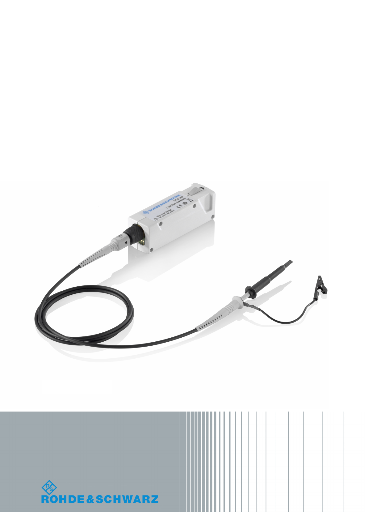
R&S®RT‑Z1M
1 MOHM Adapter
Manual
(B1OZ2)
1801314202
Manual
Version 02
Page 2

This user manual describes the usage of the R&S RT-Z1M 1 MOhm adapter (1337.9200.02).
© 2019 Rohde & Schwarz GmbH & Co. KG
Mühldorfstr. 15, 81671 München, Germany
Phone: +49 89 41 29 - 0
Fax: +49 89 41 29 12 164
Email: info@rohde-schwarz.com
Internet: www.rohde-schwarz.com
Subject to change – Data without tolerance limits is not binding.
R&S® is a registered trademark of Rohde & Schwarz GmbH & Co. KG.
Trade names are trademarks of the owners.
1801.3142.02 | Version 02 | R&S®RT‑Z1M
Throughout this manual, products from Rohde & Schwarz are indicated without the ® symbol, e.g. R&S®RT-Z1M is indicated as
R&S RT-Z1M.
Page 3

R&S®RT‑Z1M
2.1 Key Features and Key Characteristics........................................................................7
2.2 Unpacking the Instrument............................................................................................7
2.2.1 Inspecting the Contents.................................................................................................. 8
2.3 Description of the Adapter........................................................................................... 8
2.3.1 Adapter Box.................................................................................................................... 9
2.3.2 Probe Interface................................................................................................................9
2.3.3 Dimensions of Adapter and Probe................................................................................ 10
2.4 Accessories................................................................................................................. 10
Contents
Contents
1 Safety Information..................................................................................5
2 Product Description...............................................................................7
2.4.1 Supplied Accessories....................................................................................................10
2.4.2 Service Accessories......................................................................................................10
3 Putting into Operation......................................................................... 11
3.1 Connecting the Adapter to the Oscilloscope........................................................... 11
3.2 Identification of Adapter and Probe.......................................................................... 12
3.3 Connecting the Adapter to the DUT.......................................................................... 12
3.4 Disconnecting the Adapter from the DUT.................................................................12
3.5 Using the Adapter....................................................................................................... 12
3.5.1 Offset Compensation.....................................................................................................13
3.5.2 AC/DC Switching...........................................................................................................13
3.5.3 Analog Bandwidth......................................................................................................... 13
3.5.4 Self-alignment............................................................................................................... 14
3.5.5 R&S ProbeMeter........................................................................................................... 14
4 Typical Characteristics ....................................................................... 15
4.1 Bandwidth....................................................................................................................15
4.2 Step Response............................................................................................................ 15
5 Maintenance and Service.................................................................... 17
5.1 Service Strategy.......................................................................................................... 17
5.2 Returning for Servicing.............................................................................................. 17
5.3 Cleaning....................................................................................................................... 17
3Manual 1801.3142.02 ─ 02
Page 4

R&S®RT‑Z1M
5.4 Calibration Interval......................................................................................................18
5.5 Discarding the Product...............................................................................................18
Contents
6 Functional Check................................................................................. 19
4Manual 1801.3142.02 ─ 02
Page 5

R&S®RT‑Z1M
Safety Information
1 Safety Information
Safety information is part of the product documentation. It warns you about the potential dangers and gives instructions how to prevent personal injury or damage caused
by dangerous situations. Safety information is provided as follows:
●
The printed "Basic Safety Instructions" in different languages are delivered with the
product.
●
Throughout the documentation, safety instructions are provided when you need to
take care during setup or operation.
Also, read and observe the safety instructions of the oscilloscope to which the adapter
is connected.
Risk of shock hazard and injury
To avoid electric shock and personal injury, observe the following instructions:
●
The adapter and the measurement instrument must be grounded. Grounding is
typically ensured through the grounding of the measurement instrument to which
the adapter is connected.
●
Always connect the adapter to the oscilloscope first before connecting a probe to
the adapter and to the circuit under test.
●
Do not apply voltages higher than the maximum rated voltage, see the imprint on
the adapter.
●
When using the adapter in combination with a passive probe that can measure voltages higher than the maximum rated input voltage of the adapter (e.g. R&S RTZP10): Observe the maximum rated voltage of the probe.
●
Do not operate the adapter if any part is damaged, or with suspected failures. If
you detect or suspect any damage to the adapter or probe, have it inspected by
qualified service personnel.
5Manual 1801.3142.02 ─ 02
Page 6

R&S®RT‑Z1M
Safety Information
Risk of device damage
The R&S RT‑Z1M can withstand a moderate amount of physical and electrical stress.
To avoid damage, treat the adapter with care:
●
Do not exceed the specified voltage limits.
●
Connect the R&S RT‑Z1M only to an instrument with Rohde & Schwarz probe
interface. Never connect it to a usual BNC jack. Although the 7 mm coaxial connector looks like a standard BNC connector, it is constructed differently and does
not fit to the standard BNC jack. The interface of the R&S RT‑Z1M can withstand a
higher frequency limit.
●
Prevent the adapter from receiving mechanical shock.
●
Do not spill liquids on the adapter.
●
Store the adapter in a shock-resistant case, e.g. in the foam-lined shipping case.
6Manual 1801.3142.02 ─ 02
Page 7

R&S®RT‑Z1M
2.1 Key Features and Key Characteristics
Product Description
Unpacking the Instrument
2 Product Description
The R&S RT‑Z1M 1 MOhm adapter is an accessory for oscilloscopes that have only
inputs with 50 Ω input impedance. It allows you to connect measurement equipment
requiring a 1 MΩ load impedance to such oscilloscopes.
The R&S RT‑Z1M is equipped with the Rohde & Schwarz probe interface to be connected to Rohde & Schwarz oscilloscopes that are compatible with this interface. However, oscilloscopes that already support a 1 MΩ input impedance do not support the
adapter.
The Rohde & Schwarz probe interface at the adapter input allows you to connect various probes, e.g. passive probes, current probes, and active probes with
Rohde & Schwarz probe interface.
The R&S RT‑Z1M provides an integrated R&S ProbeMeter, which is used for probes
without an own R&S ProbeMeter. Usually, these probes are passive probes.
Table 2-1: Key features and key characteristics
Parameter R&S RT‑Z1M
Max. Bandwidth
Low Pass1:
Low Pass2:
Operating voltage window ±60 V (adapter alone)
Maximum input voltage 60 V DC
Offset range Up to ±60 V depending on vertical scale
Input resistance 1 MΩ
Input capacitance 12 pF
AC coupling Cutoff frequency: 7 Hz
R&S ProbeMeter, dynamic range ±60 V
R&S ProbeMeter, measurement error < 0.1 %
R&S probe interface +5 V USB Power; 0.5 A current limited
DC - 500 MHz
DC - 200 MHz
DC - 20 MHz
42 V AC Peak
+12 high-power supply; 1 A current limited
2.2 Unpacking the Instrument
The following items are included in the delivery:
●
R&S RT‑Z1M 1 MOhm adapter
7Manual 1801.3142.02 ─ 02
Page 8

R&S®RT‑Z1M
2.2.1 Inspecting the Contents
Product Description
Description of the Adapter
●
User manual of the R&S RT‑Z1M
●
R&S RT-ZP10 10:1 passive probe
●
User manual of the R&S RT-ZP10
●
Accessories for R&S RT-ZP10 (delivery contents is listed in the user manual of the
probe)
●
R&S RT‑Z1M data sheet
●
"Basic Safety Instructions" brochure
●
Calibration certificate
●
Documented calibration values (if ordered)
●
Inspect the package for damage.
Keep the package and the cushioning material until the contents have been
checked for completeness and the device has been tested.
If the packaging material shows any signs of stress, notify the carrier and your
Rohde & Schwarz service center. Keep the package and cushioning material for
inspection.
●
Inspect the adapter.
If there is any damage or defect, or if the R&S RT‑Z1M 1 MOhm adapter does not
operate properly, notify your Rohde & Schwarz service center.
●
Inspect the accessories.
If the contents are incomplete or damaged, notify your Rohde & Schwarz service
center.
A description of the supplied probe accessories is listed in the user manual of
R&S RT-ZP10 passive probe.
2.3 Description of the Adapter
Figure 2-1: R&S
RT‑
Z1M 1 MOhm adapter with R&S RT-ZP10 passive probe
8Manual 1801.3142.02 ─ 02
Page 9

R&S®RT‑Z1M
2.3.1 Adapter Box
2.3.2 Probe Interface
Product Description
Description of the Adapter
1 = Adapter box
2 = R&S Probe interface to connect an active probe to the adapter, and a contact ring to connect a passive
probe
3 = R&S Probe interface to connect the adapter to an oscilloscope
4 = Release knob
5 = R&S RT-ZP10 passive probe
The adapter box contains active circuitry to attenuate, amplify or filter the incoming signal and pass it to the 50 Ω input of the oscilloscope. There are no controls or indicators
on the adapter box.
The R&S RT‑Z1M is designed for connection to the Rohde & Schwarz probe interface
of the oscilloscope. The interface provides also a USB interface and supply voltages
(+5 V USB, +12 V high power). It transmits analog signals and digital data simultaneously.
The output of the R&S RT‑Z1M is connected to the oscilloscope. It consists of a male
precision 7 mm (276 mil) coaxial connector and six pogo pins to ensure a thorough
connection.
Probes are connected to the input of the R&S RT‑Z1M. The Rohde & Schwarz probe
interface at the input provides the power supply and USB interface to recognize and
support active probes. It has also a contact ring to recognize a passive probe by its
read out pin. In any case, the probe is recognized automatically by the oscilloscope.
Figure 2-2: Output interface of the adapter
1 = Rohde & Schwarz probe interface with 7 mm (276 mil) coaxial connector and six pogo pins
2 = Release knob
9Manual 1801.3142.02 ─ 02
Page 10

R&S®RT‑Z1M
2.3.3 Dimensions of Adapter and Probe
Product Description
Accessories
The R&S RT‑Z1M 1 MOhm adapter and the R&S RT-ZP10 passive probe have the following dimensions (all values in mm):
Figure 2-3: Dimensions of the R&S RT‑Z1M adapter with R&S RT-ZP10
2.4 Accessories
2.4.1 Supplied Accessories
Table 2-2 lists the accessories supplied with the R&S RT‑Z1M 1 MOhm adapter. To
order additional probes from Rohde & Schwarz, use the order number provided in the
table.
Table 2-2: Supplied accessories
Item Quantity Description Order number
R&S RT-ZP10 with probe accessories 1 10:1 passive Probe 1409.7550.00
2.4.2 Service Accessories
To order accessories for servicing the probe, contact your Rohde & Schwarz service
center. The following accessories are available:
Table 2-3: Service accessories
Item Description
R&S RT-ZK1 The service kit is used to calibrate the adapter, to do per-
formance tests, and for servicing. The service kit includes
all adapters and accessories to connect the adapter to the
required measuring instruments.
R&S RT‑Z1M Service Manual The service manual contains a detailed description of the
performance test to verify the specifications, and other
important service procedures.
10Manual 1801.3142.02 ─ 02
Page 11

R&S®RT‑Z1M
Putting into Operation
Connecting the Adapter to the Oscilloscope
3 Putting into Operation
Risk of shock hazard and injury
Read and observe the instructions in Chapter 1, "Safety Information", on page 5 before
using the adapter.
During usage, the probe slightly heats up. Warming is normal behavior and not a sign
of malfunction.
The R&S RT‑Z1M works only with oscilloscopes that have only inputs with 50 Ω input
impedance. Oscilloscopes that already support a 1 MΩ input impedance do not support
the adapter.
3.1 Connecting the Adapter to the Oscilloscope
► Connect the adapter (1) to the Rohde & Schwarz probe interface of the oscillo-
scope (2).
The adapter snaps in when connected properly to the port.
Figure 3-1: Connecting the R&S
RT‑
Z1M to the Rohde & Schwarz oscilloscope
► To disconnect the adapter:
a) Press and hold the release button (3).
b) Pull the adapter away from the oscilloscope.
11Manual 1801.3142.02 ─ 02
Page 12

R&S®RT‑Z1M
3.2 Identification of Adapter and Probe
3.3 Connecting the Adapter to the DUT
Putting into Operation
Using the Adapter
When the R&S RT‑Z1M is connected to the oscilloscope, the oscilloscope recognizes
the adapter and reads out the specific parameters from the data memory of the
adapter.
When a probe is connected to the adapter, the oscilloscope also reads the probe-specific parameters through the adapter.
For information on probe-specific settings and information, refer to the oscilloscope's
user manual.
Observe the following step order when connecting the components of the measurement setup. Also read and observe the instructions in Chapter 1, "Safety Information",
on page 5.
1. Make sure that the oscilloscope is properly grounded.
2. Connect the adapter to the oscilloscope.
3. Connect the probe to the adapter.
4. Switch off the test circuit.
5. Connect the probe to the DUT. Ensure a stable connection between the DUT and
the probe.
6. Switch on the test circuit.
3.4 Disconnecting the Adapter from the DUT
Observe the following step order when disconnecting the measurement setup. Also
read and observe the instructions in Chapter 1, "Safety Information", on page 5.
1. Switch off the test circuit.
2. Disconnect the probe from the DUT.
3. Disconnect the probe from the adapter.
4. Disconnect the adapter from the oscilloscope.
3.5 Using the Adapter
All settings of the R&S RT‑Z1M are adjusted on the oscilloscope.
12Manual 1801.3142.02 ─ 02
Page 13

R&S®RT‑Z1M
3.5.1 Offset Compensation
Putting into Operation
Using the Adapter
These settings are:
●
Offset
●
Input coupling
●
Lowpass filter (bandwidth)
●
Self-alignment
The gain or attenuation of the adapter is automatically set by the oscilloscope depending on the vertical scale.
The DC offset voltage is subtracted from the signal at the input of the R&S RT‑Z1M.
The offset is part of the vertical settings of the channel to which the adapter is connected. For details, refer to the user manual of the Rohde & Schwarz oscilloscope.
Figure 3-2: Offset of R&S RT‑Z1M with R&S RT-ZP10, signal range 1V/Div
3.5.2 AC/DC Switching
Without the adapter, the input coupling is limited to "DC" for a 50 Ω input impedance.
When the R&S RT‑Z1M adapter is connected to the channel input, AC coupling is also
possible. Note that the R&S ProbeMeter does not show the correct DC voltage on the
probe tip if AC coupling is active.
The coupling is part of the vertical settings of the channel to which the adapter is connected. For details, refer to the user manual of the Rohde & Schwarz oscilloscope.
3.5.3 Analog Bandwidth
The R&S RT‑Z1M features two lowpass filters of 200 MHz and 20 MHz. The filters
reduce bandwidth and thus noise during the measurement.
13Manual 1801.3142.02 ─ 02
Page 14

R&S®RT‑Z1M
3.5.4 Self-alignment
3.5.5 R&S ProbeMeter
Putting into Operation
Using the Adapter
The bandwidth filter is part of the vertical settings of the channel to which the adapter is
connected. For details, refer to the user manual of the Rohde & Schwarz oscilloscope.
The R&S RT‑Z1M has a self-alignment function. Self-alignment compensates measurement errors caused by a termination impedance slightly different from 50 Ω, or an
ambient temperature different from the one at which the factory alignment was done.
When the adapter is detached from the oscilloscope, the values of the self-alignment
are discarded, and the original factory-alignment is reloaded. Thus, repeat the selfalignment when you reattach the probe.
The self-alignment of the adapter is part of the probe settings of the channel to which
the adapter is connected. For details, refer to the user manual of the Rohde & Schwarz
oscilloscope.
The R&S ProbeMeter is an integrated voltmeter that measures DC voltages with higher
precision compared to the oscilloscope's DC accuracy. The DC measurement is performed continuously and in parallel to the time domain measurement of the oscilloscope.
When the R&S ProbeMeter is active, the measured values are displayed on the oscilloscope. The R&S ProbeMeter state is part of the probe settings of the channel to which
the adapter is connected. For details, refer to the user manual of the Rohde & Schwarz
oscilloscope.
Advantages of the R&S ProbeMeter:
●
Measures DC voltages of different levels, no need to adjust the measurement
range of the oscilloscope.
●
True DC measurement (integration time > 100 ms), not mathematical average of
displayed waveform.
●
High measurement accuracy and low temperature sensitivity.
●
Simple means of setting the oscilloscope's trigger level and vertical scaling if a
waveform is not visible.
●
Independent of oscilloscope settings for offset, position, vertical scale, horizontal
scale, and trigger.
With adapter, you can use the R&S ProbeMeter also with passive probes, which do not
have an own R&S ProbeMeter. In this combination, the R&S ProbeMeter of the
adapter takes effect. Note that the R&S ProbeMeter does not show the correct DC voltage on the probe tip if AC coupling is active. Active probes that have a R&S ProbeMeter use their own one as usual, the R&S ProbeMeter of the adapter is not used.
14Manual 1801.3142.02 ─ 02
Page 15

R&S®RT‑Z1M
4.1 Bandwidth
Typical Characteristics
Step Response
4 Typical Characteristics
The R&S RT‑Z1M 1 MOhm adapter has several gain or attenuation modes. The mode
of the adapter, and thus the gain or attenuation, depends on the vertical scale and is
set automatically by the oscilloscope to achieve optimized system behavior.
The R&S RT‑Z1M has a bandwidth of 500 MHz. You can reduce the bandwidth to 200
MHz or 20 MHz, see Chapter 3.5.3, "Analog Bandwidth", on page 13. The transfer
functions of the gain or attenuation modes are shown in Figure 4-1.
The bandwidth of a system specifies the maximum frequency at which a purely sinusoidal signal is still transferred at 70 % (–3 dB) of its amplitude.
The bandwidth of the whole measurement setup also depends on the bandwidth of the
probe connected to the R&S RT‑Z1M, and the bandwidth of the oscilloscope.
Figure 4-1: Amplitude/frequency response of the R&S RT‑Z1M, all 7 modes
4.2 Step Response
The step response up to 20 ns of the R&S RT‑Z1M 1 MOhm adapter is shown in Fig-
ure 4-2. The propagation delay is normalized to the beginning of the step. The ampli-
tude is normalized to the steady state value.
15Manual 1801.3142.02 ─ 02
Page 16

R&S®RT‑Z1M
BW
t
rise
4.0
Typical Characteristics
Step Response
Figure 4-2: Step response of the R&S RT‑Z1M (all 7 modes)
The rise time of a system is inversely proportional to the bandwidth. The following
approximation applies:
The minimum measurable rise time of the whole setup also depends on the bandwidth
of the probe connected to the R&S RT‑Z1M, and the bandwidth of the oscilloscope.
16Manual 1801.3142.02 ─ 02
Page 17

R&S®RT‑Z1M
5.1 Service Strategy
5.2 Returning for Servicing
Maintenance and Service
Cleaning
5 Maintenance and Service
Like all Rohde & Schwarz products, Rohde & Schwarz probes and adapters are of high
quality and require only minimum service and repair. However, if service is needed,
contact your Rohde & Schwarz service center. Return a defective product to the Rohde
& Schwarz service center for diagnosis and exchange.
You can return the R&S RT‑Z1M 1 MOhm adapter for calibration. The service personnel carry out the required tests.
Use the original packaging to return your R&S RT‑Z1M to your Rohde & Schwarz service center. A list of all service centers is available on:
www.services.rohde-schwarz.com
If you cannot use the original packaging, consider the following:
1. Use a sufficiently sized box.
2. Protect the product from damage and moisture (e.g. with bubble wrap).
3. Use some kind of protective material (e.g. crumpled newspaper) to stabilize the
product inside the box.
4. Seal the box with tape.
5. Address the package to your nearest Rohde & Schwarz service center.
5.3 Cleaning
Product damage caused by cleaning agents
Cleaning agents contain substances that can damage the product, for example, solvent can damage the labeling or plastic parts.
Never use cleaning agents such as solvents (thinners, acetone, etc.), acids, bases or
other substances.
17Manual 1801.3142.02 ─ 02
Page 18

R&S®RT‑Z1M
5.4 Calibration Interval
5.5 Discarding the Product
Maintenance and Service
Discarding the Product
To clean the exterior of the product, use a soft cloth moistened with either distilled
water or isopropyl alcohol. Before using the product again, make sure to dry it completely.
The recommended calibration interval for R&S RT‑Z1M 1 MOhm adapter is two years.
For servicing, send the probe to your nearest Rohde & Schwarz service center (see
Chapter 5.2, "Returning for Servicing", on page 17).
Handle and dispose the product in accordance with local regulations.
18Manual 1801.3142.02 ─ 02
Page 19

R&S®RT‑Z1M
Functional Check
6 Functional Check
The functional check confirms the basic operation of the R&S RT‑Z1M 1 MOhm
adapter and the R&S RT-ZP10 passive probe using simple measurement equipment.
The functional check is not suitable to verify compliance with the specifications of the
R&S RT‑Z1M 1 MOhm adapter, because the test results are influenced by the used
oscilloscope.
Figure 6-1: Functional check
1. Connect the R&S
"Connecting the Adapter to the Oscilloscope", on page 11.
2. Connect the R&S RT-ZP10 probe to the probe interface of the adapter.
3.
Connect the probe tip to the square wave output of the oscilloscope.
4.
Connect the ground lead to the probe ground connector
5. Press the [Preset] and then the [Autoset] key on the oscilloscope.
A square wave between 0 V and 1 V is displayed on the oscilloscope screen.
RT‑Z1M to an R&S oscilloscope as described in Chapter 3.1,
of the oscilloscope.
19Manual 1801.3142.02 ─ 02
 Loading...