

R&S®RTC1000
Digital Oscilloscope
User Manual
(=S×Â2)
1335735202
Version 06

This document describes the following R&S RTC1000 models:
●
R&S®RTC1000 (1335.7500K02)
© 2022 Rohde & Schwarz GmbH & Co. KG
Muehldorfstr. 15, 81671 Muenchen, Germany
Phone: +49 89 41 29 - 0
Email: info@rohde-schwarz.com
Internet: www.rohde-schwarz.com
Subject to change – data without tolerance limits is not binding.
R&S® is a registered trademark of Rohde & Schwarz GmbH & Co. KG.
Trade names are trademarks of the owners.
1335.7352.02 | Version 06 | R&S®RTC1000
Throughout this manual, products from Rohde & Schwarz are indicated without the ® symbol, e.g. R&S®RTC1000 is indicated as
R&S RTC1000.

R&S®RTC1000
1.1 Safety Instructions........................................................................................................7
1.2 Korea Certification Class A..........................................................................................8
2.1 Manuals and Instrument Help...................................................................................... 9
2.2 Data Sheet and Brochure........................................................................................... 10
2.3 Calibration Certificate.................................................................................................10
2.4 Release Notes, Open Source Acknowledgment...................................................... 10
3.1 Preparing for Use........................................................................................................ 11
Contents
Contents
1 Safety Information..................................................................................7
2 Documentation Overview......................................................................9
3 Getting Started..................................................................................... 11
3.2 Instrument Tour........................................................................................................... 15
4 Operating Basics..................................................................................20
4.1 Control Panel...............................................................................................................20
4.2 Display......................................................................................................................... 23
4.3 Operating Concept......................................................................................................24
4.4 Integrated Help............................................................................................................ 25
4.5 Signal Display..............................................................................................................25
4.6 General Instrument Settings...................................................................................... 29
4.7 Self-Alignment.............................................................................................................30
4.8 Firmware Update......................................................................................................... 31
4.9 Options.........................................................................................................................32
5 Waveform Setup...................................................................................35
5.1 Vertical Setup.............................................................................................................. 35
5.2 Horizontal Setup..........................................................................................................40
5.3 Acquisition Setup........................................................................................................41
6 Trigger...................................................................................................48
6.1 Setting Up the Trigger.................................................................................................48
6.2 General Trigger Settings............................................................................................ 49
6.3 Edge Trigger................................................................................................................ 50
6.4 Pulse Trigger............................................................................................................... 52
3User Manual 1335.7352.02 ─ 06

R&S®RTC1000
6.5 Logic Trigger............................................................................................................... 53
6.6 Video Trigger............................................................................................................... 56
6.7 Trigger Out Pulses...................................................................................................... 57
6.8 External Trigger Input.................................................................................................57
7.1 Zoom Function............................................................................................................ 59
7.2 Marker Function.......................................................................................................... 61
7.3 XY-Display....................................................................................................................63
7.4 Mathematics................................................................................................................ 64
7.5 Frequency Analysis (FFT).......................................................................................... 72
7.6 Pass/Fail Test Based on Masks................................................................................. 76
7.7 Component Test.......................................................................................................... 78
Contents
7 Analysis................................................................................................ 59
7.8 Digital Voltmeter.......................................................................................................... 82
8 Measurements......................................................................................84
8.1 Quick View................................................................................................................... 84
8.2 Cursor Measurements................................................................................................ 85
8.3 Automatic Measurements.......................................................................................... 88
9 Documenting Results.......................................................................... 95
9.1 Saving and Loading Instrument Settings................................................................. 95
9.2 Reference Waveforms.................................................................................................98
9.3 Waveforms (Traces).................................................................................................. 100
9.4 Screenshots...............................................................................................................104
9.5 Quick Access with FILE/PRINT Key........................................................................ 106
10 Mixed Signal Operation (Option R&S RTCB1).................................108
10.1 Using Logic Channels.............................................................................................. 108
10.2 Logic Trigger for Digital Input.................................................................................. 111
10.3 Cursor Measurements for Logic Channels............................................................. 111
10.4 Automatic Measurements for Logic Channels....................................................... 112
10.5 Using Logic Channels in Buses...............................................................................112
11 Signal Generation (Option R&S RTCB6).......................................... 115
11.1 Function Generator...................................................................................................115
11.2 Pattern Generator......................................................................................................116
4User Manual 1335.7352.02 ─ 06

R&S®RTC1000
12 Serial Bus Analysis............................................................................121
12.1 Bus Configuration.....................................................................................................121
12.2 Bus Table: Decode Results...................................................................................... 123
Contents
12.3
12.4 SPI / SSPI BUS (Option R&S RTCK1)...................................................................... 131
12.5 UART/RS-232 BUS (Option R&S RTCK2)................................................................136
12.6 CAN Bus (Option R&S RTCK3)................................................................................ 142
12.7 LIN Bus (Option R&S RTCK3).................................................................................. 148
I2C Bus (Option R&S RTCK1)...................................................................................125
13 Network Connections and Remote Operation.................................155
13.1 LAN Connection........................................................................................................ 155
13.2 Remote Access Using a Web Browser....................................................................158
13.3 USB Connection........................................................................................................163
13.4 Switching to Remote Control...................................................................................167
14 Remote Commands Reference.........................................................168
14.1 Conventions Used in Remote Command Description...........................................168
14.2 Common Commands................................................................................................ 168
14.3 Acquisition and Setup.............................................................................................. 172
14.4 Trigger........................................................................................................................198
14.5 Display....................................................................................................................... 207
14.6 Measurements........................................................................................................... 215
14.7 Quickmath and Reference Waveforms....................................................................228
14.8 FFT..............................................................................................................................236
14.9 Masks......................................................................................................................... 240
14.10 Function Generator...................................................................................................247
14.11 Pattern Generator......................................................................................................248
14.12 Digital Voltmeter........................................................................................................ 254
14.13 Counter...................................................................................................................... 257
14.14 Component Tester.....................................................................................................257
14.15 External input............................................................................................................ 258
14.16 Protocol Analysis......................................................................................................262
14.17 Data and File Management.......................................................................................315
14.18 General Instrument Setup........................................................................................ 324
14.19 Status Reporting....................................................................................................... 327
5User Manual 1335.7352.02 ─ 06

R&S®RTC1000
15 Contacting Customer Support..........................................................333
A SCPI Command Structure................................................................. 334
A.1 Syntax for Common Commands............................................................................. 334
A.2 Syntax for Instrument-Specific Commands........................................................... 335
A.3 SCPI Parameters....................................................................................................... 336
A.4 Overview of Syntax Elements.................................................................................. 339
A.5 Structure of a Command Line..................................................................................340
A.6 Responses to Queries.............................................................................................. 341
B Command Sequence and Synchronization..................................... 343
B.1 Preventing Overlapping Execution......................................................................... 343
Contents
Annex.................................................................................................. 334
C Status Reporting System.................................................................. 346
C.1 Structure of a SCPI Status Register........................................................................ 346
C.2 Hierarchy of status registers................................................................................... 347
C.3 Contents of the Status Registers............................................................................ 349
C.4 Application of the Status Reporting System.......................................................... 354
C.5 Reset Values of the Status Reporting System....................................................... 356
D General Programming Recommendations...................................... 357
List of commands.............................................................................. 358
6User Manual 1335.7352.02 ─ 06

R&S®RTC1000
1 Safety Information
Safety Information
Safety Instructions
The R&S RTC1000 digital oscilloscope is designed for measurements on circuits that
are only indirectly connected to the mains or not connected at all. It is not rated for any
measurement category.
The instrument is rated for pollution degree 2 - for indoor, dry location use where only
non-conductive pollution occurs. Temporary conductivity caused by condensation is
possible.
The instrument is intended for use in industrial areas. When used in residential areas,
radio disturbances caused by the instrument can exceed given limits. Additional shielding can be required.
The instrument must be controlled by personnel familiar with the potential risks of measuring electrical quantities. Observe applicable local or national safety regulations and
rules for the prevention of accidents.
Safety information is part of the product documentation. It warns you about the potential dangers and gives instructions how to prevent personal injury or damage caused
by dangerous situations. Safety information is provided as follows:
●
The "Basic Safety Instructions" in different languages are delivered as a printed
brochure with the instrument.
●
Throughout the documentation, safety instructions are provided when you need to
take care during setup or operation.
1.1 Safety Instructions
To prevent electric shock, personal injury or fire, follow these rules:
●
Do not open the instrument casing.
●
Do not use the instrument if you detect or suspect any damage of the instrument or
accessories.
●
Do not operate the instrument in wet, damp or explosive atmospheres.
●
Make sure that the instrument is properly grounded.
●
Do not use the instrument to ascertain volt-free state.
●
Do not exceed the voltage limits given in Chapter 3.2.1.1, "Input Connectors",
on page 16.
An unsuitable operating site or test setup can damage the instrument and connected
devices. Ensure the following operating conditions before you switch on the instrument:
●
Read and observe the "Basic Safety Instructions" brochure and the safety instructions in the manuals.
●
Observe the operating conditions specified in the data sheet. Note that the general
safety instructions also contain information on operating conditions.
●
Position the instrument as described in the following sections.
7User Manual 1335.7352.02 ─ 06

R&S®RTC1000
1.2 Korea Certification Class A
Safety Information
Korea Certification Class A
Make sure that all fan openings are unobstructed and the airflow perforations are
unimpeded. The minimum distance from the wall is 10 cm.
●
Signal levels at the input connectors are all within the specified ranges.
●
Signal outputs are correctly connected and are not overloaded.
이 기기는 업무용(A급) 전자파 적합기기로서 판매자 또는 사용자는 이 점을 주의하시기
바라며, 가정외의 지역에서 사용하는 것을 목적으로 합니다.
8User Manual 1335.7352.02 ─ 06

R&S®RTC1000
2 Documentation Overview
2.1 Manuals and Instrument Help
Documentation Overview
Manuals and Instrument Help
This section provides an overview of the R&S RTC1000 user documentation.
You find the manuals on the product page at:
www.rohde-schwarz.com/manual/rtc1000
Getting started manual
Introduces the R&S RTC1000 and describes how to set up the product. A printed English version is included in the delivery.
User manual
Contains the description of all instrument modes and functions. It also provides an
introduction to remote control, a complete description of the remote control commands
with programming examples, and information on maintenance and instrument interfaces. Includes the contents of the getting started manual.
The online version of the user manual provides the complete contents for immediate
display on the internet.
Instrument help
The help offers quick, context-sensitive access to the functional description directly on
the instrument.
Basic safety instructions
Contains safety instructions, operating conditions and further important information.
The printed document is delivered with the instrument.
Instrument security procedures manual
Deals with security issues when working with the R&S RTC1000 in secure areas.
Service manual
Describes the performance test for checking the rated specifications, module replacement and repair, firmware update, troubleshooting and fault elimination, and contains
mechanical drawings and spare part lists. The service manual is available for registered users on the global Rohde & Schwarz information system (GLORIS, https://
gloris.rohde-schwarz.com).
9User Manual 1335.7352.02 ─ 06

R&S®RTC1000
2.2 Data Sheet and Brochure
2.3 Calibration Certificate
2.4 Release Notes, Open Source Acknowledgment
Documentation Overview
Release Notes, Open Source Acknowledgment
The data sheet contains the technical specifications of the R&S RTC1000. It also lists
the options with their order numbers and optional accessories. The brochure provides
an overview of the instrument and deals with the specific characteristics.
See www.rohde-schwarz.com/brochure-datasheet/rtc1000
The document is available on https://gloris.rohde-schwarz.com/calcert. You need the
device ID of your instrument, which you can find on a label on the rear panel.
The release notes list new features, improvements and known issues of the current
firmware version, and describe the firmware installation. The open source acknowledgment document provides verbatim license texts of the used open source software. It
can also be read directly on the instrument.
See www.rohde-schwarz.com/firmware/rtc1000.
10User Manual 1335.7352.02 ─ 06

R&S®RTC1000
3 Getting Started
3.1 Preparing for Use
3.1.1 Unpacking and Checking the Instrument
Getting Started
Preparing for Use
1. Inspect the package for damage.
If the packaging material shows any signs of stress, notify the carrier who delivered
the instrument.
2. Carefully unpack the instrument and the accessories.
3. Check the equipment for completeness. See section "Delivery contents"
on page 11.
4. Check the equipment for damage.
If there is damage, or anything is missing, immediately contact the carrier as well
as your distributor. Make sure not to discard the box and packing material.
Packing material
Retain the original packing material. If the instrument needs to be transported or shipped later, you can use the material to protect the control elements and connectors.
Delivery contents
The delivery package contains the following items:
●
R&S RTC1000 digital oscilloscope
●
R&S RT-ZP03 probe probes (2x)
●
Country-specific power cable
●
Printed "Getting Started" manual
●
Printed "Basic Safety Instructions" brochure
3.1.2 Positioning the Instrument
The instrument is designed for use under laboratory conditions. It can be used in
standalone operation on a bench top or can be installed in a rack.
For standalone operation, place the instrument on a horizontal bench with even, flat
surface. The instrument can be used in horizontal position, or with the support feet on
the bottom extended.
11User Manual 1335.7352.02 ─ 06
R&S®RTC1000
Getting Started
Preparing for Use
The instrument can be installed in a 19" rack mount using a rack mount kit. The order
number of the rack mount kit is given in the data sheet. The installation instructions are
part of the rack mount kit.
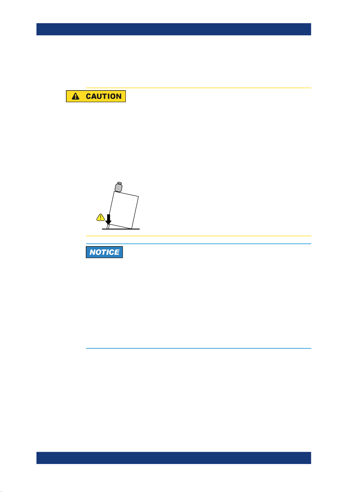
Risk of injury if feet are folded out
The feet can fold in if they are not folded out completely or if the instrument is shifted.
This can cause damage or injury.
●
Fold the feet completely in or out to ensure stability of the instrument. Never shift
the instrument when the feet are folded out.
●
When the feet are folded out, do not work under the instrument or place anything
underneath.
●
The feet can break if they are overloaded. The overall load on the folded-out feet
must not exceed 200 N.
F
max
Risk of instrument damage due to overheating
An insufficient airflow can cause the R&S RTC1000 to overheat, which can impair the
measurement results, disturb the operation, and even cause damage.
●
Ensure that all fan openings are unobstructed and that the airflow perforations are
unimpeded. The minimum distance to a wall is 10 cm.
●
When placing several instruments side by side, keep a minimum distance of 20 cm
between the instruments. Ensure that the instruments do not draw in the preheated
air from their neighbors.
●
When mounting the instrument in a rack, observe the instructions of the rack manufacturer to ensure sufficient airflow and avoid overheating.
3.1.3 Starting the Instrument
3.1.3.1 Powering On
The R&S RTC1000 can be used with different AC power voltages and adapts itself
automatically to it.
12User Manual 1335.7352.02 ─ 06

R&S®RTC1000
Getting Started
Preparing for Use
The nominal ranges are:
●
100 V to 240 V AC at 50 Hz to 60 Hz, or 100 V to 120 V at 400 Hz
●
max. 25 W
Risk of injury
Connect the instrument only to an outlet that has a ground contact.
Do not use an isolating transformer to connect the instrument to the AC power supply.
1. Connect the power cable to the AC power connector on the rear panel of the
R&S RTC1000.
2. Connect the power cable to the socket outlet.
3. Switch the main power switch at the rear of the instrument to position I.
The [ON/OFF] key lights up when the instrument is in standby mode. The key is
located next to the upper right corner of the screen.
You can leave the main power switch on to preserve your last instrument settings. To
disconnect from power supply, power off the instrument.
3.1.3.2 Starting Up and Shutting Down
To start up the instrument
1. Make sure that the R&S RTC1000 is connected to the AC power supply and the
main power switch on the rear panel is in position I.
2. Press the [ON/OFF] key. The key is located next to the upper right corner of the
screen.
The instrument performs a system check and starts the firmware. If the previous
session was terminated regularly, the oscilloscope uses the last settings.
Table 3-1: Colors of the [ON/OFF] key
Unlit Instrument is on: firmware is working
Red Standby: instrument is off, main power switch is on
Warm-up and prepare the instrument
Make sure that the instrument has been running and warming up before you start the
self-alignment and the measurements. The minimum warm-up time is about 20 min.
To shut down the instrument to standby state
► Press the [ON/OFF] key.
13User Manual 1335.7352.02 ─ 06

R&S®RTC1000
3.1.3.3 Powering Off
Getting Started
Preparing for Use
All current settings are saved, and the software shuts down. Now it is safe to power
off the instrument.
Powering off is required only if the instrument must be disconnected from all power
supplies.
1. If the instrument is running, press the [ON/OFF] key on the front panel to shut
down the instrument.
2. Switch the main power switch at the rear of the instrument to position 0.
3. Disconnect the AC power cable from the AC power supply.
Risk of losing data
If you switch off the running instrument using the rear panel switch or by disconnecting
the power cord, the instrument loses its current settings. Furthermore, program data
can be lost.
Press the ON/OFF key first to shut down the application properly.
3.1.3.4 EMI Suppression
Electromagnetic interference (EMI) may affect the measurement results.
To suppress generated electromagnetic interference (EMI):
●
Use suitable shielded cables of high quality. For example, use double-shielded RF
and LAN cables.
●
Always terminate open cable ends.
●
Note the EMC classification in the data sheet.
3.1.4 Replacing the Fuse
The instrument is protected by a fuse. You can find it on the rear panel between the
main power switch and AC power supply.
Type of fuse: Size 5x20 mm, 250V~, T2.5H (slow-blow), IEC60127-2/5
14User Manual 1335.7352.02 ─ 06

R&S®RTC1000
3.2 Instrument Tour
Getting Started
Instrument Tour
Risk of electric shock
The fuse is part of the main power supply. Therefore, handling the fuse while power is
on can lead to electric shock. Before opening the fuse holder, make sure that the
instrument is switched off and disconnected from all power supplies.
Always use fuses supplied by Rohde & Schwarz as spare parts, or fuses of the same
type and rating.
1. Pull the fuse holder out of its slot on the rear panel.
2. Exchange the fuse.
3. Insert the fuse holder carefully back in its slot until it latches.
3.2.1 Front Panel
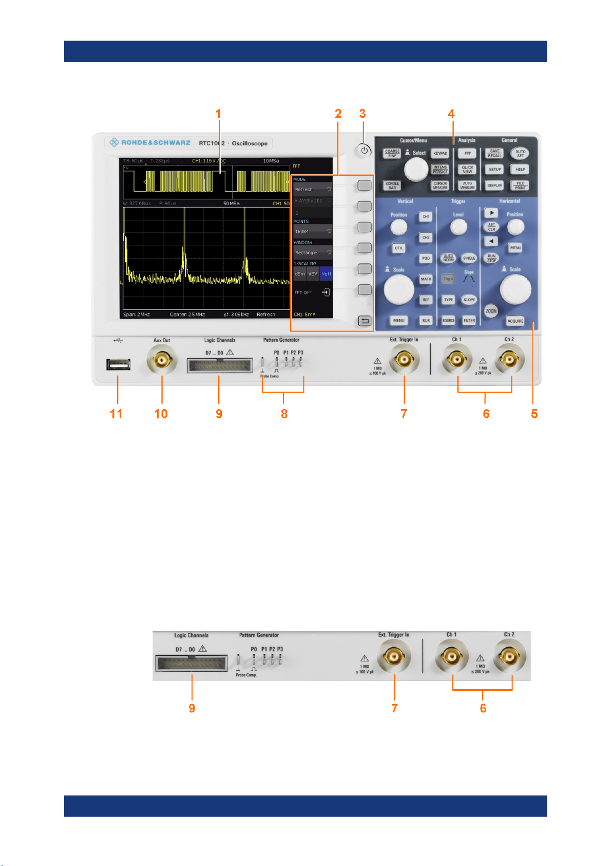
Figure 3-1 shows the front panel of the R&S RTC1000. The function keys are grouped
in functional blocks to the right of the display.
15User Manual 1335.7352.02 ─ 06
R&S®RTC1000
Getting Started
Instrument Tour
Figure 3-1: Front view of the R&S RTC1000
1 = Display
2 = Softkeys and menu
3 = [ON/OFF] key
4 = Cursor/Menu, Analyze and General sections
5 = Vertical, Trigger and Horizontal sections
6 = BNC connectors of the analog channel inputs
7 = BNC connector of the external trigger input
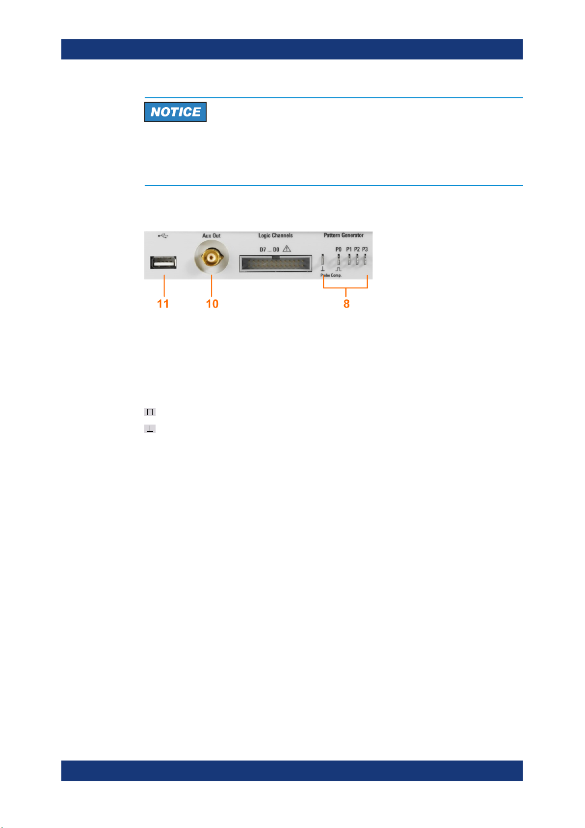
8 = Pattern generator output (option R&S RTCB6) and probe adjustment output
9 = Connector for the logic probe (option R&S RTCB1)
10 = Multi-purpose BNC connector [Aux Out]
11 = USB connector
3.2.1.1 Input Connectors
16User Manual 1335.7352.02 ─ 06
R&S®RTC1000
Getting Started
Instrument Tour
BNC inputs (6, 7)
The R&S RTC1000 has two channel inputs (6) to connect the input signals. The external trigger input (7) is used to control the measurement by an external signal. The trigger level can be set from -5 V to 5 V.
The input impedance of all BNC inputs is 1 MΩ.
Risk of electrical shock - maximum input voltages
The maximum input voltage on channel inputs must not exceed 200 V (peak) and
150 V (RMS).
For the external trigger input, the maximum input voltage is 100 V (peak) and
70 V (RMS).
Transient overvoltages must not exceed 200 V (peak).
Voltages higher than 30 V (RMS) or 42 V (peak) or 60 V DC are regarded as hazardous contact voltages. When working with hazardous contact voltages, use appropriate
protective measures to preclude direct contact with the measurement setup:
●
Use only insulated voltage probes, test leads and adapters.
●
Do not touch voltages higher than 30 V (RMS) or 42 V (peak) or 60 V DC.
Risk of injury and instrument damage
The instrument is not rated for any measurement category. When measuring in circuits
with transient overvoltages of category II, III or IV circuits, make sure that no such
overvoltages reach the R&S RTC1000 input. Therefore, use only probes that comply
with DIN EN 61010-031. When measuring in category II, III or IV circuits, always insert
a probe that appropriately reduces the voltage so that no transient overvoltages higher
than 200 V (peak) are applied to the instrument. For detailed information, refer to the
documentation and safety information of the probe manufacturer.
Explanation: According to section AA.2.4 of EN 61010-2-030, measuring circuits without any measurement category are intended for measurements on circuits which are
not directly connected to the mains.
Logic probe (9)
The connector for logic channels can be used if the Mixed Signal Option R&S RTCB1
is installed. The option provides a logical probe with 8 digital channels (D0 to D7).
The maximum input voltage is 40 V (peak) at 100 kΩ input impedance. The maximum
input frequency for a signal with the minimum input voltage swing and medium hysteresis of 800 mV (Vpp) is 300 MHz.
17User Manual 1335.7352.02 ─ 06
R&S®RTC1000
3.2.1.2 Other Connectors on the Front Panel
Getting Started
Instrument Tour
Risk of instrument damage
Use the connector for the active logic probe exclusively for the logic probe R&S RTZL03, which is delivered with option R&S RTCB1. Connecting other probe types can
demolish the input.
[Pattern Generator] (8)
Connectors for the pattern generator P0, P1, P2, P3.
[Probe Comp.] (8)
Probe compensation terminal to support adjustment of passive probes to the oscilloscope channel.
[Aux Out] (10)
Multi-purpose BNC output that can function as pass/fail and trigger output, output for
component testing, and as function generator output (with option R&S RTCB6).
[USB] type A (11)
USB 2.0 type A interface to connect a USB flash drive for storing and reloading instrument settings and measurement data, and to update the firmware.
3.2.2 Rear Panel
Figure 3-2 shows the rear panel of the R&S RTC1000 with its connectors.
On the back panel of the instrument, you find Ethernet and USB interfaces. Optional
interfaces are not available.
Square wave signal for probe compensation.
Ground connector for probes.
18User Manual 1335.7352.02 ─ 06
R&S®RTC1000
Getting Started
Instrument Tour
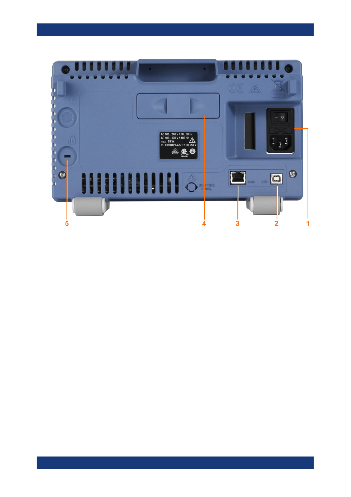
Figure 3-2: Rear panel view of R&S RTC1000
1 = AC power supply connector and main power switch
2 = USB connector, type B
3 = LAN connector
4 = not used
5 = Kensington lock slot to secure the instrument against theft
AC supply: mains connector and main power switch (1)
The instrument supports a wide range power supply. It automatically adjusts to the correct range for the applied voltage. There is no line voltage selector.
The AC main power switch disconnects the instrument from the AC power line.
[USB] type B (2)
USB 2.0 interface of type B (device USB) to connect a printer, or for remote control of
the instrument.
Note: Electromagnetic interference (EMI) can affect the measurement results. To avoid
any impact, use only USB connecting cables with a maximum length of 1 m.
[LAN] (3)
8-pin connector RJ-45 used to connect the instrument to a Local Area Network (LAN).
It supports up to 100 Mbit/s.
19User Manual 1335.7352.02 ─ 06
R&S®RTC1000
4 Operating Basics
4.1 Control Panel
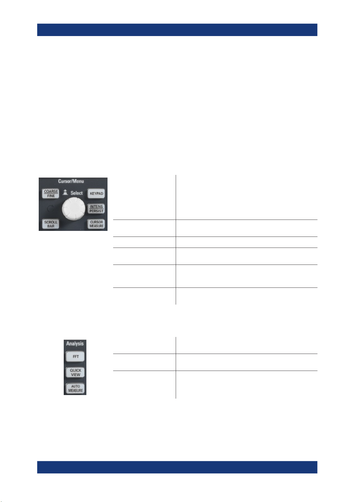
4.1.1 Cursor/Menu Section
Operating Basics
Control Panel
The controls on the front panel allow access to all basic functions. Advanced settings
are easily accessible using the menu structure and gray softkeys. The [ON/OFF] button is clearly set apart by its design. The most important controls have colored LEDs,
indicating the current setting.
Universal rotary knob
[COARSE/FINE] Toggles between coarse and fine resolution of the universal
[SCROLLBAR] Activates or deactivates the virtual screen.
KEYPAD Opens the on-screen keypad. The key is illuminated if the key-
INTENS/PERSIST The first keypress sets the rotary knob to adjust the intensity of
[CURSOR MEASURE] Activates the cursors and opens the menu to set up cursor mea-
4.1.2 Analysis Section
[FFT] Starts a Fast Fourier Transformation and switches to frequency
The action of the universal knob depends on the selection in the
menu:
●
Set a numeric value
●
Select a value in a list
●
Navigate through the menus
●
Select a highlighted value by pressing the knob, for example, in the keypad.
rotary knob. The key lights up if fine resolution is active.
pad can be used.
the waveforms (key is illuminated). The second keypress opens
the menu to adjust all intensities and the persistence.
surements.
domain.
[QUICK VIEW] Starts the quick measurements and shows the typical character-
istics of the signal.
[AUTO MEASURE] Opens a menu to set up automatic measurements. Up to 6 mea-
surements can be performed at the same time.
20User Manual 1335.7352.02 ─ 06
R&S®RTC1000
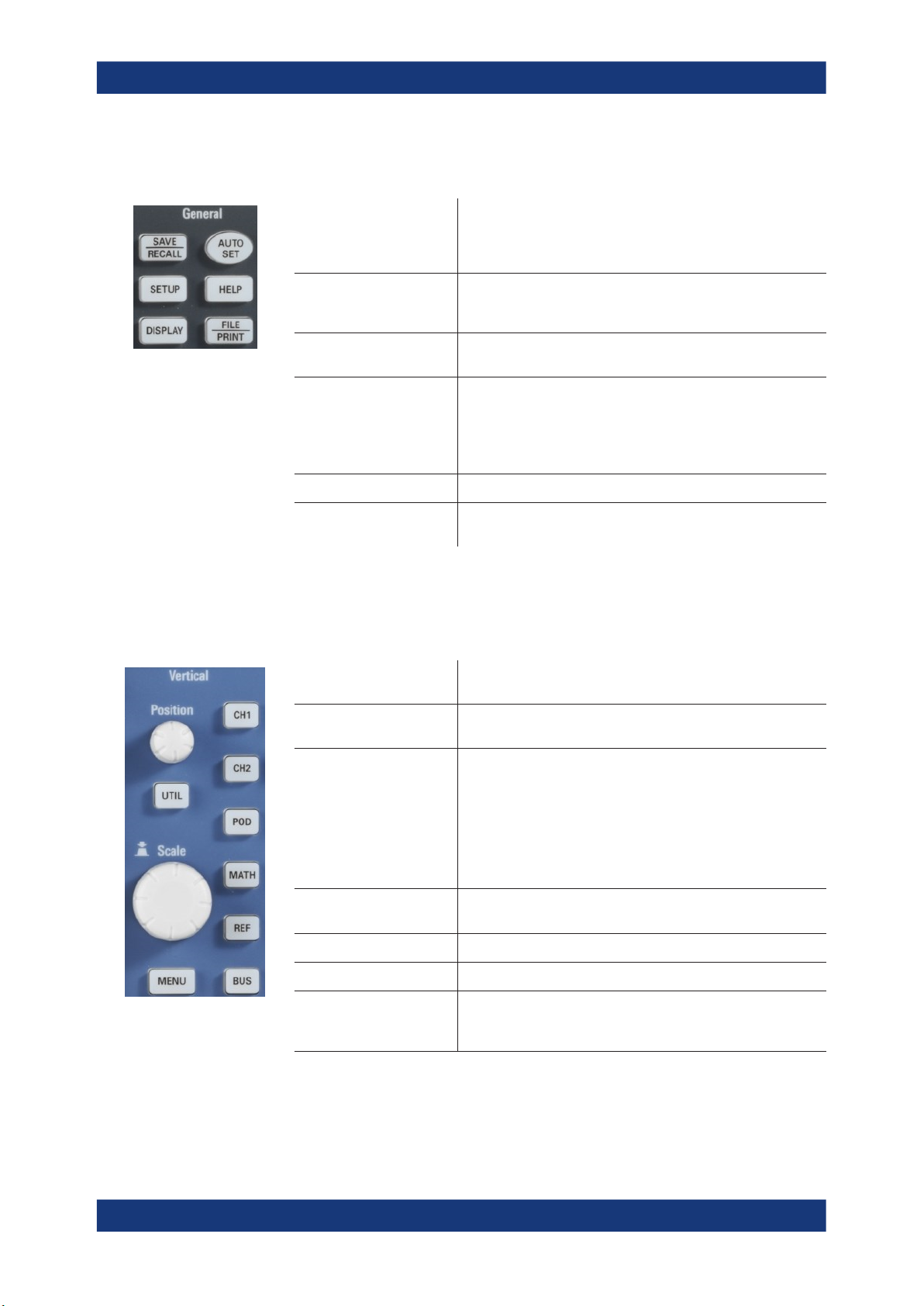
4.1.3 General Section
Operating Basics
Control Panel
[SAVE/RECALL] Opens a menu to load and save instrument settings, reference
signals, waveforms, screenshots of the display, and formularies.
In the menu, you can also assign the function of the [FILE/
PRINT] key.
[SETUP] Opens the menu of general instrument settings, such as lan-
guage, interfaces, date, time, firmware update, options, printer,
and more.
[DISPLAY] Opens a menu to activate the virtual screen, and to adjust the
display settings.
[AUTOSET] Press shortly to perform automatic setup. The instrument ana-
lyzes the active signals, and adjusts the horizontal, vertical, and
trigger settings to display stable waveforms.
Press and hold the key until you hear a beep. The most important settings of the scope are reset to their defaults.
[HELP] Opens a window with the integrated help.
[FILE/PRINT] Depending on the assigned function, [FILE/PRINT] can save
instrument settings, signals, screenshots, or start a printout.
4.1.4 Vertical Section
The Vertical section features all controls for analog channels.
[Position] knob Sets the vertical position of the selected waveform. To switch to
[Scale] knob Sets the vertical scale (vertical gain) of the selected waveform.
[CH1], [CH2] Activate the channel if the channel is off.
[POD] Activates the logic channels if optional logic probe R&S RT-ZL03
[REF] Opens the menu to create, save and load reference waveforms.
[MATH] Opens a menu to create, save and load calculated waveforms.
[BUS] Activates the serial and parallel bus analysis. Requires at least
fine tuning of the value, press the knob.
The scale value is shown below the grid.
Selects the channel if the channel is on and the other channel is
selected.
Switches off the channel if it is selected.
If a channel is selected, its key is illuminated. If a channel is on
but not selected, you see the signal on the display, and its key
does not light up.
is connected. Requires option R&S RTCB1.
one of the options R&S RTCB1, R&S RTCK1, R&S RTCK2, or
R&S RTCK3.
21User Manual 1335.7352.02 ─ 06
R&S®RTC1000
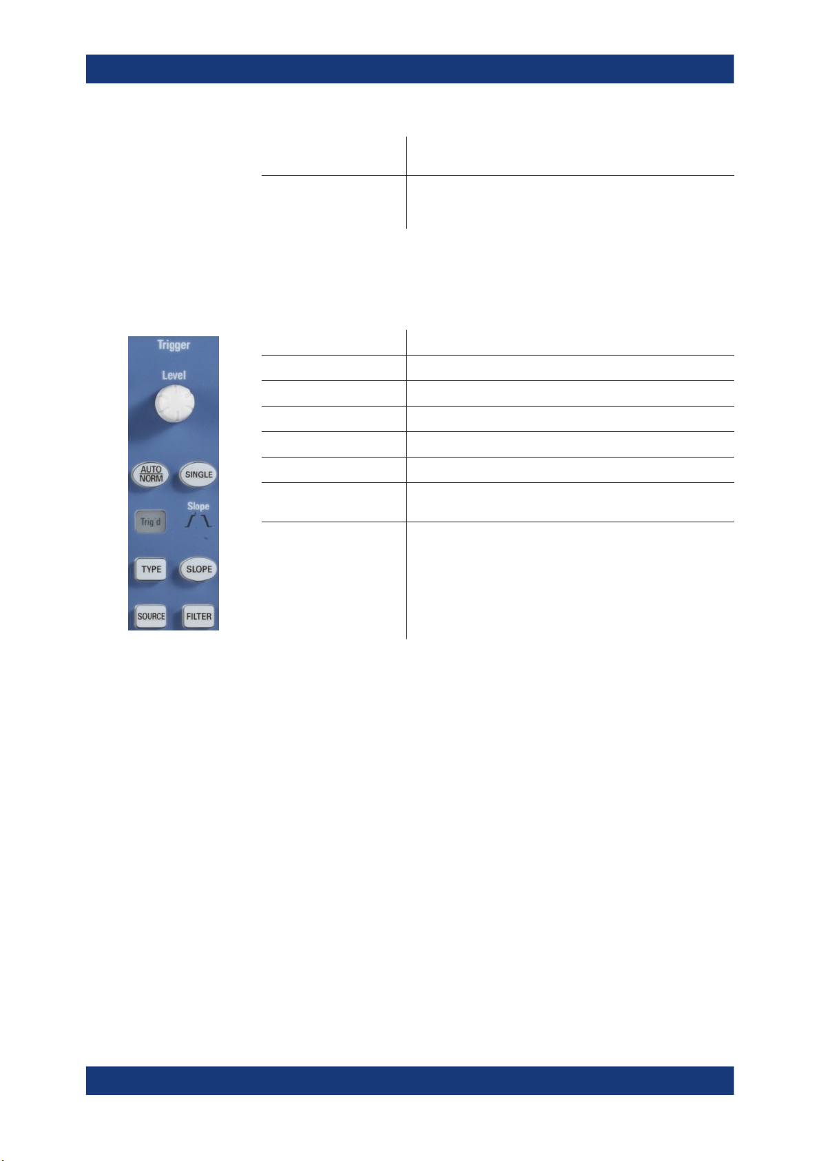
4.1.5 Trigger Section
Operating Basics
Control Panel
[MENU] Opens the advanced menu for the selected waveform, bus or
pod.
[UTIL] Opens a menu with more applications: digital voltmeter, function
and pattern generator (requires option R&S RTCB6), component
tester, and trigger counter.
The Trigger section provides all controls to adjust the trigger.
[LEVEL] knob Sets the trigger level.
[AUTO/NORM] Toggles between auto and normal trigger mode.
Trigg'd The LED lights up if the instrument found a trigger event.
[TYPE] Opens a menu to select the trigger type.
[SOURCE] Opens a menu to select the trigger source.
[SINGLE] Starts a single acquisition.
[SLOPE] Selects the slope for the edge trigger, or the polarity for the pulse
[FILTER] Opens a menu to set up the trigger condition for the selected trig-
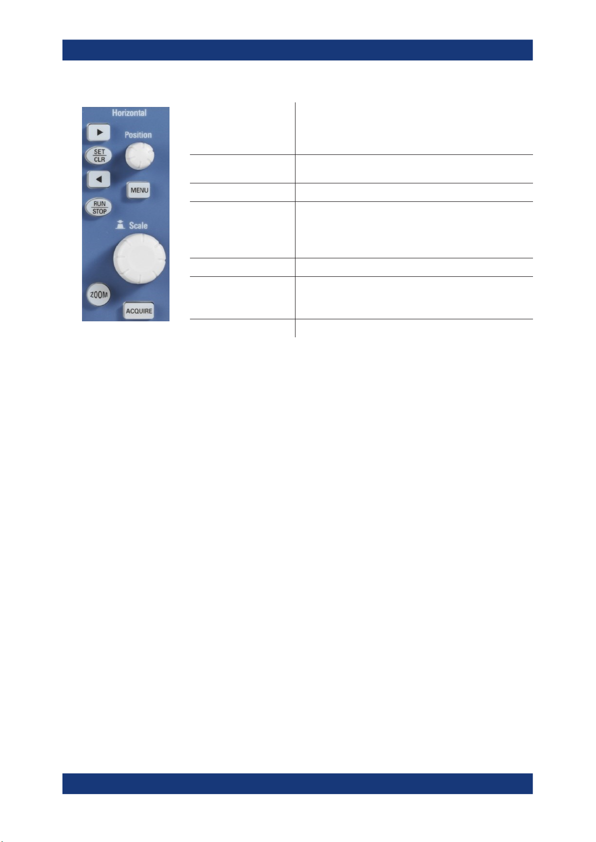
4.1.6 Horizontal Section
In the Horizontal section, you set the horizontal and acquisition settings, zoom, and
markers.
trigger. The selection is indicated by the Slope LEDs.
ger type.
22User Manual 1335.7352.02 ─ 06
R&S®RTC1000
Operating Basics
Display
4.2 Display
[Left Arrow ], [Right Arrow] /
[SET/CLR]
[RUN/STOP] Starts and stops continuous data acquisition. The key lights up in
[ZOOM] Activates and deactivates the zoom display.
[Position] knob Sets the trigger position (horizontal position). The maximum
[MENU] Opens a menu to set the trigger position.
[Time base] knob Sets the horizontal scale (time base) for all waveforms. The
[ACQUIRE] Opens a menu to select the acquisition mode and record mode.
Set and deletes markers, and navigate markers.
If no markers are set, the arrow keys move the trigger position by
5 division to the left or right. [SET/CLR] resets the value to the
time reference point.
red if acquisition is stopped.
value depends on the time base.
If a zoom window is active, the knob sets the zoom position.
If markers are set, the knob sets the marker position.
scale value is shown above the grid on the left.
If a zoom window is active, the knob sets the zoom size.
The R&S RTC1000 is equipped with a TFT color monitor with LED backlight and VGA
resolution (640x480 pixels). If the soft menu is closed, the display has 12 scale divisions on the time axis. If the menu is shown, 10 divisions are shown. In vertical direction, the display has 8 divisions.
23User Manual 1335.7352.02 ─ 06

R&S®RTC1000
Operating Basics
Operating Concept
1 2 4 5 6 7 8
2
3
12
11
9 10
1 = Horizontal scale (time base), in s/div
2 = Trigger position
3 = Time reference, zero point of the time axis
4 = Trigger settings: source, level, type, and filter conditions
5 = Sample rate
6 = Acquisition mode
7 = Vertical scrollbar, visible if virtual screen with 20 vertical divisions is on
8 = Short menu with most important settings of the selected channel
9 = Vertical settings of active waveforms: vertical scale in V/div, coupling, and bandwidth limit (if set). Chan-
nel 1 is selected.
10 = Measurement results
11 = Reference potentials of the channels
12 = Trigger level
4.3 Operating Concept
The general operating concept is based on a few key principals, recurring with various
settings and functions:
●
Keys work in one of these ways:
– The key opens a soft menu when pressed once. It closes the soft menu when
pressed a second time.
– The key activates a specific function. Pressing this key a second time deacti-
vates the function.
24User Manual 1335.7352.02 ─ 06

R&S®RTC1000
Operating Basics
Signal Display
●
Depending on the requirements, the [Universal] knob in the Cursor/Menu section
either selects a value, or navigates through menus. The COARSE/FINE key toggles between fine and coarse resolution of the [Universal] knob.
●
The "MENU OFF" key below the softkeys closes the current menu, or switches to
the next higher level.
●
The effect of channel keys depends on the state of the selected waveform:
– Activate the channel if the channel is off.
– Selects the channel if the channel is on and the other channel is selected.
– Switches off the channel if it is selected.
– If a channel is selected, its key is illuminated. If a channel is on but not
selected, you see the signal on the display, and its key does not light up.
The menus include some navigation elements and usage principles.
●
Press the softkey to select or toggle a value. The selected value is marked in blue.
●
Some functions must be activated and require value selection. Pressing the softkey
toggles between "OFF" and the last set value. Use the [Universal] knob to change
the value.
●
A round arrow in the softkey indicates that the value is set with the [Universal]
knob.
●
A small triangle on the bottom right of a softkey indicates an additional menu level.
●
If additional menu pages are available, the lowest softkey navigates through the
menu pages. The current page is shown in the soft menu.
4.4 Integrated Help
The integrated help shows explanatory text about the selected function. The text in the
help window is dynamically updated when you select another function.
1. To activate the integrated help, press the [HELP] key in the General section.
The help window opens, and the [HELP] key lights up.
2. If you no longer need help, press [HELP] again.
4.5 Signal Display
This chapter describes the display of signals and the available display modes.
4.5.1 Display Settings
► To adjust the display, press the [DISPLAY] key.
25User Manual 1335.7352.02 ─ 06

R&S®RTC1000
Operating Basics
Signal Display
Figure 4-1: Display menu, page 1/2 (left) and page 2/2 (right)
VIRTUAL SCREEN
See Chapter 4.5.2, "Virtual Screen", on page 27.
DOTS ONLY
If enabled, only the acquired data points are shown. The data points are not connected
by lines. If disabled, interpolated data points are also shown, and the waveform is a
continuous line.
INVERSE BRIGHTN.
Iinverts the brightness of the displayed signals points. Normally, frequently captured
dots are displayed more brightly than rare dots. If inverted, rare events are displayed
with higher brightness. To capture rare events in a signal, this setting can be used in
combination with persistence.
FALSE COLORS
Converts the brightness level of the displayed signal points to a color scale, ranging
from blue, magenta, red and yellow to white. Due to the higher contrast, you can see
signal details easily. This setting applies to all signals.
GRID
Sets the display of the grid: "LINES", "RETICLE", or "OFF".
INFO WINDOW
Info windows are small windows that appear on the screen depending on the current
application. You can change the format of information windows:
"TRANSPARENCY"
Use the Universal knob to or the [KEYPAD] to change the value from
0% to 100%.
26User Manual 1335.7352.02 ─ 06

R&S®RTC1000
Operating Basics
Signal Display
"POSITION"
"ACQ.STATUS"
AUX. CURSORS
You can enable or disable the cursor and channel markers on the display. Select
"DEFAULTS" to rest the settings.
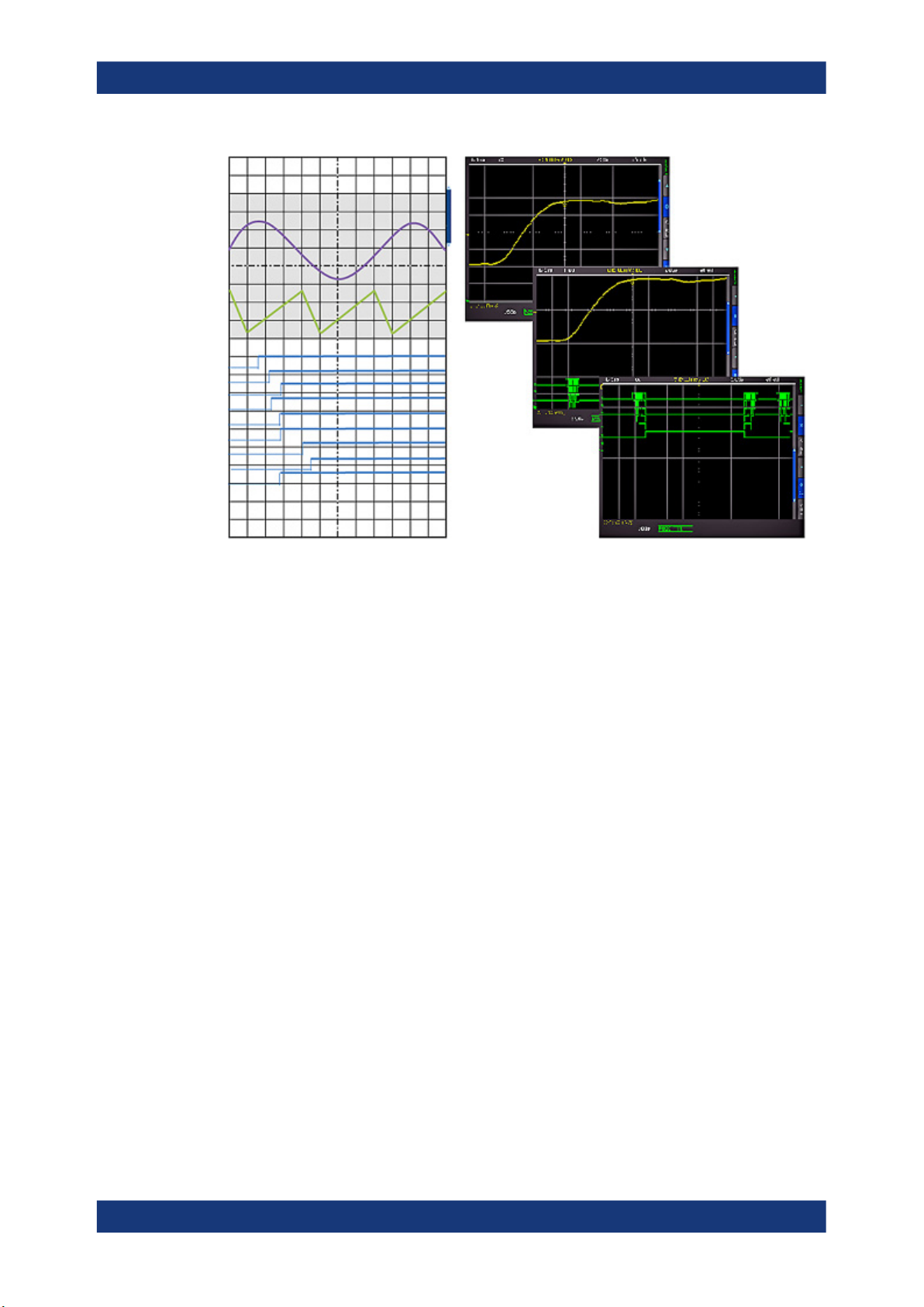
4.5.2 Virtual Screen
Normally, the grid of the R&S RTC1000 has 8 vertical divisions. It has also a virtual
range of 20 divisions. These virtual divisions can be used entirely by the optional digital
channels D0 to D7, the mathematical channels and the references signals. The analog
channels can use up to ±10 divisions from the center. This allows a simple and clear
display of many waveforms
Figure 4-2 illustrates the functionality of the virtual screen. The scroll bar next to the
grid indicates the position of the 8 visible divisions within the available 20 divisions. .
If activated and the vertical position is changed, the value of the vertical position is shown at the zero line.
If activated, the information on the acquisition status is shown. In normal trigger mode, if the trigger condition is fulfilled, the information
window shows a progress display for the post-trigger and pre-trigger.
If the trigger condition is not met, the information window shows the
time since the last trigger event ("Trig?"). In automatic trigger mode,
no information is shown.
1. Press the [DISPLAY] key in the General section.
2. Activate "VIRTUAL SCREEN".
A scrollbar is shown to the right of the grid.
3. To activate or deactivate the scrollbar, press the [ SCROLL BAR] key.
The scrollbar is shown in blue if it is active.
4. If the scrollbar is active, use the Universal knob to move the display window within
the 20 divisions of the virtual screen.
27User Manual 1335.7352.02 ─ 06
R&S®RTC1000
Operating Basics
Signal Display
Figure 4-2: Drawing of the virtual screen area
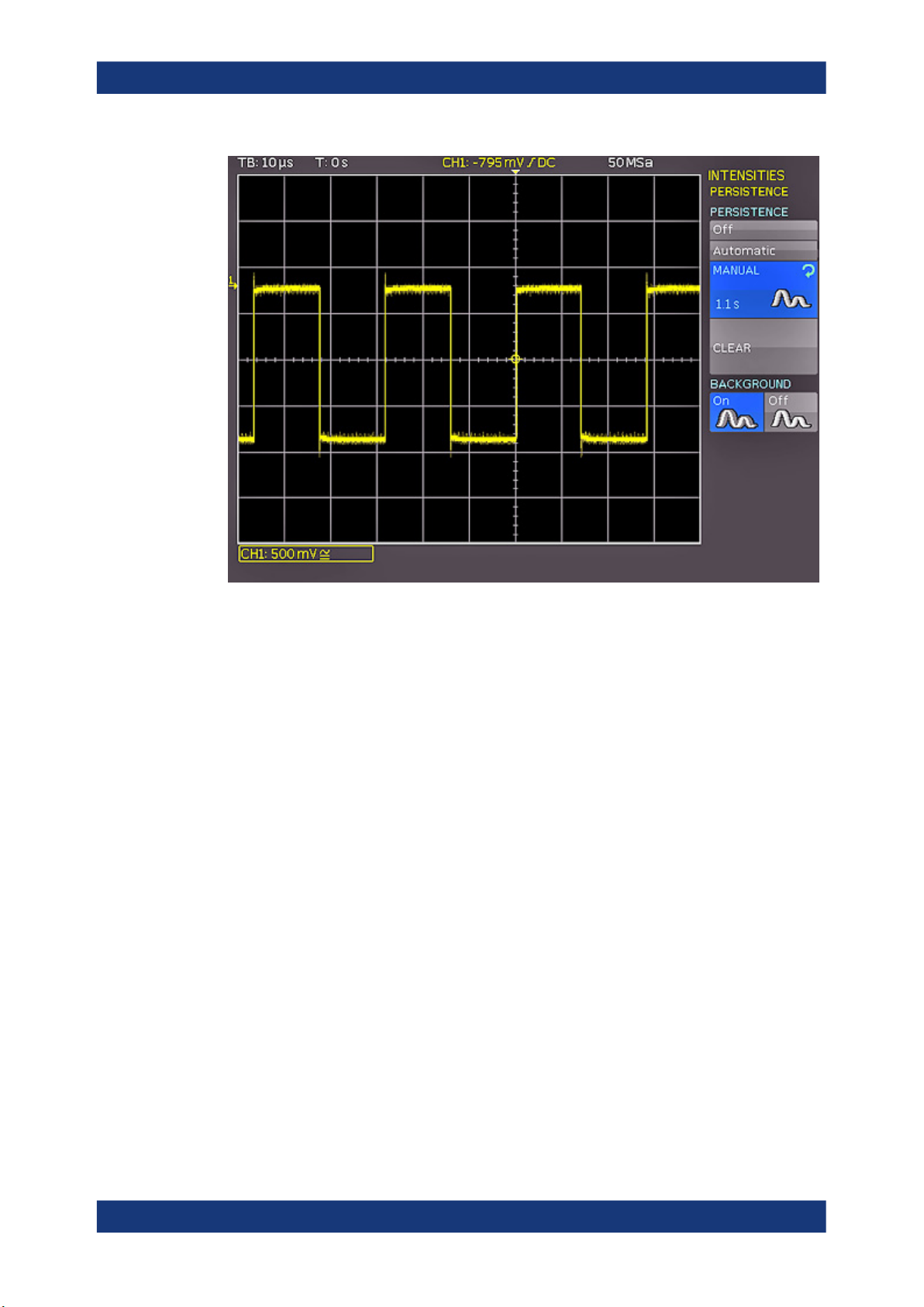
4.5.3 Signal Intensity and Persistence
To change the intensity of the waveforms:
1. Press the [INTENS/PERSIST] key in the Cursor/Menu section until it lights up in
white.
2. Turn the Universal knob to change the intensity of the signal display from 0% to
100%.
To access further intensity and persistence settings:
1. If the [INTENS/PERSIST] key is illuminated in white, press this key again.
2. Use the menu functions to adjust the settings.
The following settings are available:
TRACE, GRID, BACKLIGHT
Use the Universal knob to adjust the waveform intensities, grid intensity, and the backlighting.
PERSISTENCE
Persistence defines how subsequent captured waveforms are shown simultaneously.
Older waveforms are displayed in darker color (they fade), and newer waveforms are
displayed in lighter color. Thus, signals points occurring more frequently are displayed
in lighter color. The display is similar to that of an analog oscilloscope
28User Manual 1335.7352.02 ─ 06
R&S®RTC1000
Operating Basics
General Instrument Settings
Figure 4-3: Persistence function
"MANUAL"
"AUTOMATIC"
"OFF"
"BACKGROUND"
You can set a duration of 50 ms to infinite by using the [universal]
knob or the [KEYPAD] key. If a finite duration is selected, new signals
are written on top of one another. The most recent captures are displayed more brightly than older signals. For example, if 300 ms is
selected, the display of the waveform becomes darker in 50 ms intervals and is erased after 300 ms.
The instrument sets the optimal persistence time.
Persistence is deactivated.
When enabled, older waveforms do not disappear entirely after the
set persistence time. Instead, waveforms are displayed in the background with low brightness. This display is useful for the analysis of
peak values in signals, for example.
4.6 General Instrument Settings
The instrument settings are provided in the "SETUP" menu.
► Press the [SETUP] key in the General section.
29User Manual 1335.7352.02 ─ 06

R&S®RTC1000
Operating Basics
Self-Alignment
"LANGUAGE" Selects the language for user interface and help.
"SELF ALIGNMENT" The instrument adjusts vertical accuracy, time base and several
trigger settings and saves the identified correction data internally.
See also: Chapter 4.7, "Self-Alignment", on page 30.
"PROBE ADJUST" Aligns the probe. A wizard explains all steps on the display.
"INTERFACE" Configures the USB and Ethernet (LAN) interfaces.
See also: Chapter 13, "Network Connections and Remote Opera-
tion", on page 155.
"DEVICE INFORMATION" Shows detailed information on hardware and software of the
instrument.
"UPDATE" Firmware update, see Chapter 4.8, "Firmware Update",
on page 31.
"OPTIONS" Activation of options, see Chapter 4.9, "Options", on page 32.
"DATE & TIME" Sets the date and time.
"SOUND" You can activate a control beep to get information on the instru-
ment's activities, error beep, and trigger beep.
"DEVICE NAME" You can define a name with up to 19 characters, which is listed
"MENU OFF" Selects whether you close the menus manually, or they are closed
"DEVICE LOGO IN SCREENSHOT" If activated, the R&S logo is printed in the upper right corner of
"EDUCATION MODE" Activates and deactivates the education mode. You can set a
"PRINTER" Configures the printer, see Chapter 9.4.2, "Printing Screenshots",
4.7 Self-Alignment
The R&S RTC1000 features an integrated self-alignment procedure to achieve the
highest possible accuracy. During the standard self-alignment, the instrument adjusts
vertical accuracy, offset, time base and several trigger settings and saves the identified
correction data internally.
when screenshots are printed.
automatically after a specified time.
screenshots and printouts.
password to prevent unwanted deactivation.
In education mode, the AUTOSET, QUICK VIEW and automatic
measuring functions are disabled. This information is also shown
in the device information window.
on page 105.
Make sure that the instrument has been running and warming up for at least 20
minutes before you start the self-alignment.
Remove all probes and connected lines from the inputs.
1. Press the [SETUP] key.
30User Manual 1335.7352.02 ─ 06
 Loading...