

Rohde&Schwarz R&S®ZVR-K9 User Manual

Test and
Measurement Division
Software Manual
Virtual Embedding Networks
ZVR-K9
1106.8830.02
Printed in the Federal
Republic of Germany
1106.8830.02 1 E-5


ZVR-K9 Contents
Contents
Basics.....................................................................................................................................................1
Measuring Tasks ........................................................................................................................1
Approach ....................................................................................................................................2
System Requirements......................................................................................................................3
Installation............................................................................................................................................ 4
Getting Started....................................................................................................................................5
Preparation................................................................................................................................. 5
Importing a File Generated by a CAD Program..........................................................................5
Storing the Calibration................................................................................................................ 5
Including a Network in a Calibration........................................................................................... 6
Result.......................................................................................................................................... 6
Menu Overview................................................................................................................................... 7
File ......................................................................................................................................... 7
Measure Network ..................................................................................................................... 14
Embedding................................................................................................................................ 19
De-Embedding..........................................................................................................................20
Cal Manager............................................................................................................................. 20
Info .......................................................................................................................................21
Application Examples....................................................................................................................22
Embedding: Testing SMD Components with a Virtual Matching Network................................ 22
De-Embedding: Measurement of “Embedded“ Components................................................... 23
Measuring a Microstrip Transition ............................................................................................ 24
Index......................................................................................................................................................I.1
1106.8830.02 3 E-5

Figures ZVR-K9
List of Figures
Fig. 1: Inner and outer ports of a transformation network........................................................................1
Fig. 2: Virtual impedance matching.......................................................................................................... 1
Fig. 3: Reducing the de-embedding problem to the embedding problem................................................2
Fig. 4: Scattering parameters of virtual network getstart..........................................................................6
Fig. 5: Numbering of the ports of the transformation network..................................................................8
Fig. 6: Virtual transformation network seen as the “difference“ between a test fixture with and a test
fixture without matching network................................................................................................. 22
Fig. 7: Calibration standards for measuring a transition
from printed circuit board to ceramic substrate...........................................................................24
Fig. 8: S-parameters of a transition from PCB to ceramic substrate .....................................................25
1106.8830.02 4 E-5

ZVR-K9 Basics
Basics
Measuring Tasks
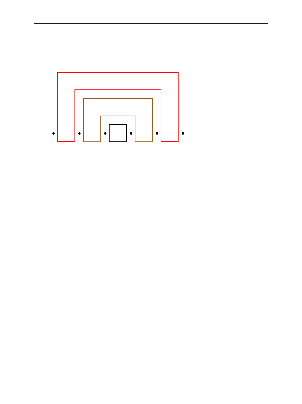
A frequently occurring category of measuring tasks in network analysis comprises the so-called
embedding and de-embedding problems. A device under test (DUT) is embedded if its ports are all
connected to a transformation network (TN) so that only the ports of the transformation network are
accessible from outside. This trans formation network may be e.g. a matching c ircuit, a test fixtur e or a
case. In general, it features twice as many ports as the DUT. The ports of the transfor mation network
which are connected to the device under test are referred to as “inner“ ports, those accessible from
outside as “outer“ ports. Fig. 1 shows an example of a two-port embedded in a trans formation network
with four ports.
TN
DUT
inner
outer
Ports of the TN
Fig. 1: Inner and outer ports of a transformation network
One possible measuring task cons ists of measuring the really existing DUT such as if it were embedded
in a transformation network , although the latter is physically not existing. In this cas e, virtual embedding
is involved. Fig. 2 shows the example of a measurement of a DUT with the input and output im pedance
, which is provided with virtual impedance transformers from Z1 to Z0 and is thus matched to the
Z
1
reference impedance Z
for the measurement.
0
NWA
(reference impedance Z
1
)
0
DUT
Z
0
Z
1
virtual impedance tran sformers Z0 : Z
Z
1
Z
0
1
Fig. 2: Virtual impedance matching
1106.8830.02 1 E-5
Basics ZVR-K9
In the opposite case, the device under test is inseparably connected with the transformation network, i.e.
the ports of the DUT are not accessible. If, nevertheles s, the S-parameters of the DUT alone are to be
determined, a “de-embedding“ problem is involved. This measuring problem can be reduced to the
embedding problem by embedding the real combination of DUT and transformation network into the
virtual inverse transformation network. The inverse and the real transformation network cancel each
other so that, viewed from outside, only the DUT is left (Fig. 3).
-1
TN (virtual)
TN (real)
DUT
Fig. 3: Reducing the de-embedding problem to the embedding problem
A third type of measuring task cons ists of the determination of the S-param eters of an unknown, but
physically existing transformation network. In the case of the two-port measurement, the difficulty is
based on the fact that the network is a four-port and, therefore, c annot directly be measured. Also the
inner and outer ports often differ in the type of transmission line (e.g. in the cas e of a test fixture f or
SMD components), which makes the calibration for a direct measurement more difficult. Measuring
tasks like that are often referred to as Unterminating problems.
Approach
The solution to embedding and de-embedding problems known so far consists of importing the Sparameters of the really existing DUT measured with a network analyzer into a CAD program and
embedding them there in a simulated circuit environment. In addition to the network analyzer, a
controller on which the CAD program runs is generally required. T he data transm is sion is in m os t c ases
effected via IEC bus. This proc edur e can har dly be performed in automatic mode, s ince eac h s imulation
requires manual user operations. Due to the data transmission and computing times, a real-time
indication, e.g. for adjustment of the DUT, is not possible.
In this case, the Software Option ZVR-K9 of the Network Analyzer ZVR offers clear advantages. The
idea is to consider the virtual transf ormation network in the system error correction data of the network
analyzer. Since a system error correction is performed anyway for almost all measuring tasks, no
additional stage of processing is required. Besides, there is no data transmission to an external
controller. Thus, the m easurement with a virtual transf ormation network is as fast as the measur ement
without one, real-time adjustment of the DUT is possible.
The S-parameters of the transformation network originate either from a CAD program or from a
measurement. The transformation network is not directly measured, but by forming the difference
between calibrations at the inner and outer ports. This avoids the through-c onnection between ports of
different types of transmission lines which would be required in the calibration for a direct measurement.
1106.8830.02 2 E-5

ZVR-K9 System Requirements
System Requirements
In order to use all features of the software option ZVR-K9, Virtual Embedding Networks, a Network
Analyzer ZVR, ZVC ZVM or ZVK is required. This manual only refers to the m odel ZVR, however, all
that is said also applies to ZVC, ZVM and ZVK. ZVR-K9 version 2.1 runs under Micr osof t Windows
or NT 4.0, for version 3.1 Windows NT 4.0 is required. On older instruments ZVR with stock no.
1043.0009.xx and ZVC with stock no. 1106.9020.xx, Windows 3.1 is part of the option ZVR-B15
(Controller). Connection of an external keyboard to the ZVR is necessary, a mouse considerably
facilitates operation as with all Windows applications. For W indows 3.1, the version num ber of the ZVR
firmware must be 1.70 or higher, for Windows NT it m ust be 3.04 or higher. T he vers ion num ber can be
polled via INFO: FIRMWARE VERSIONS.
If one ist only interested in the functions of the File m enu, that is import, export and administration of
transformation networks, one may, as well, install ZVR-K9 version 3.1 on a PC under Windows
95/98/NT4.0.
Important Note:
If ZVR-K9 runs under Windows 3.1, the files
D:\RUNTIME\RSIB\RSlB.DLL and
D:\RUNTIME\RSIB\RSDDE.DLL
3.1
must be copied to the directory
C:\WINDOWS\SYSTEM
before starting the application for the first time!
1106.8830.02 3 E-5

Installation ZVR-K9
Installation
The software option ZVR-K9 is s upplied on two installation disks. For an ins tallation on a ZVR, the k ey
code number, which can be found on the sheet “s oftware installation”, is additionally required. You may
also obtain this number from your R&S representative.
1. (only for installation on a ZVR) Enter the key sequence SETUP: OPTIONS: ENABLE NEW OPTION
on the ZVR. The input field for optional key codes will then be opened. Enter the key code number
for the option ZVR-K9. If the input is correct, the mess age “OPTION KEY OK“ will appear, otherwise
"OPTION KEY INVALID“.
2. (only for installation on a ZVR) Switch the ZVR from measurement screen to PC screen by
simultaneously pressing the keys Alt and Sys Rq on the external keyboard.
3. Insert installation disk no. 1 into the disk drive.
Windows 3.1 (only in the case of installation on a ZVR):
4. Start Windows by entering WIN.
5. Select the command Run from the File menu in the Windows program manager.
6. Enter the following text in the command line: a:\setup
Windows NT:
4. Select the command Run from the Windows Start menu.
5. Enter the following text in the Open field: a:\setup
7. Select OK.
8. Follow the instructions on the screen.
The Setup program autom atically creates all the nec essar y directories. You m ay determine the nam e of
the program group for ZVR-K9 and the de-installation program. After the installation has been
terminated, this program group is in the foreground.
1106.8830.02 4 E-5

ZVR-K9 Getting Started
Getting Started
For installation of the Software ZVR-K9, a virtual transformation network generated with the aid of a
CAD program is included. This network perm its to illus trate som e of the num erous possible applic ations
of this software option.
Preparation
Reset the ZVR to a predefined default status using PRESET and perform a full two-port user calibration
according to the TOM method over the com plete f requency range. After c alibration, establis h a throughconnection (THROUGH) between the test ports PORT 1 and PORT 2. Use the k ey combination Alt +
Sys Rq to switch over to PC operation and start W indows. Then start the application ZVR-K9 in the
program group with the same name.
First, only the main menu and the status line are visible at the lower edge of the screen. The lef t-hand
field of the status line displays the currently active input function or the current action of the program, the
right-hand field indicates the user prompts.
Importing a File Generated by a CAD Program
The demo network is provided in the data base format of Ansoft (e.g. Serenade) under the name
GETSTART in the directory c:\rsapplic\demo. To be able to use it, import and save it in the s pecif ic data
format of the Sof tware ZVR-K9. For this purpose, use the c om m and Import Network in the File menu. It
opens a window having the same name. Within the frame Select File on the left-hand side, select the file
GETSTART.FLP. Then click on the box TN1 THROUGH in the graph. The box will turn red and the
frame Select Action will appear below. In the fram e, select Insert Selected File. Now the for mat of the
import file will be checked. The following question may be answered by YES or NO, since the right
subnetwork TN2 of GETSTART.FLP is just an ideal through, too. Now the box TN1 displays the file
name instead of THROUGH. Clic k on Import Network( s). T hen follows the window Save Trans formation
Network for entering the name of the network and an optional com ment with up to 256 characters . The
Network List indicates all networks stored so f ar for inf o. By clicking on OK, the new network file will be
stored in the ZVR-K9 format, thus completing the file import.
Storing the Calibration
Next, the imported network is to be considered in the previously created user calibration, i.e. the latter is
modified. It is recom m ended to store the original c alibration status if you intend to reuse it later. For the
management of c alibration data, the c ommand Cal Manager is provided in the main menu, calling up an
interactive window. The keypad Append Active Cal to List permits to store the currently active user
calibration in the Cal List. You may define a name with a length of up to 8 characters for this calibr ation.
Vice versa, a calibration can be reactivated from the Cal List via Set Cal Active. In addition, the Cal
Manager permits you to determine in which calibration (Bas e Cal) a network is to be considered. The
current setting is indicated on the left side in the frame Bas e Cal for (De-) Embedding. You may define
either the current calibration or the one selected in the Cal List as Base Cal. Even if you have
transferred the previously created user calibration into the Cal List, it remains active and you may
maintain the default setting of the f rame Base Cal for De-( Embedding). The key Close permits to leave
the Cal Manager.
1106.8830.02 5 E-5
Getting Started ZVR-K9
Including a Networ k in a Calibration
Call up the command Embedding in the m ain menu. T he window displayed shows you the frame Base
Cal with the base calibration set in the Cal Manager, into which the network is embedded. The Network
List in the lower half of the screen lis ts all currently stored network s. Next to the nam e, you can see the
most important data at a glance, such as date, comment, point grid and frequency range. If the list
contains many entries, you will be able find the desired network f aster with these additional pieces of
information. If you have installed the Software ZVR-K9 and per formed all steps described so far, the
network list only contains the previously imported getstart. Select this network by click ing on the r elevant
line. The name will then appear in the fram e Embedding Network and the key Modify Base Cal can be
operated. Click on this key. After successful termination of embedding an appropriate message will
appear. Confirm this message and return to the main menu.
Result
You may have noticed in the last step that the status LED REM(OTE) was switched on as long as the
window Embedding was open. This LED indicates that the ZVR is under the control of the Software
ZVR-K9. In the main menu, however, this LED is always switched off. You may then switch over to
measurement s creen and operate the ZVR via the f ront panel. Switch to meas urem ent screen now and
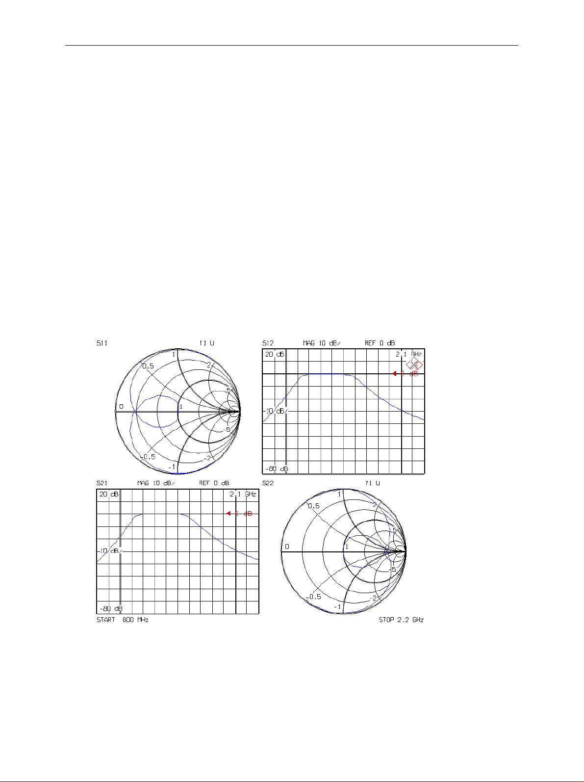
activate the four-channel display (DISPLAY: QUAD CHAN QUAD SPLIT). You will then see all the four
S-parameters of your device under test - the through-connection - as if it were embedded into a virt ual
network. This virtual network consists of an ideal bandpass filter at PORT 1 and an ideal throughconnection at PORT 2. Thus, only the S-param eters of the bandpass filter with a pas sband of 1.2 to 1.5
GHz take effect (Fig. 4).
Fig. 4: Scattering parameters of virtual network getstart
When the base calibration is modified, frequency range and point grid of the virtual network are adopted.
This is why the frequency range has also changed compared with the previous status after PRESET.
Further important functions are the measurem ent of a transformation network and the data export in
CAD file format. T his will be explained in more detail in the sections "Menu Overview" or "Application
Examples".
1106.8830.02 6 E-5
 Loading...