

Rohde&Schwarz R&S®ZVL Quick Start Guide Getting started
R&S®ZVL
Vector Network Analyzer
Quick Start Guide
1303.6538.62 – 10
Test and Measurement
Quick Start Guide

The Quick Start Guide describes all R&S®ZVL models:
● R&S® ZVL3 (frequency range up to 3 GHz), stock no. 1303.6509K03
● R&S® ZVL6 (frequency range up to 6 GHz), stock no. 1303.6509K06
● R&S® ZVL3-75 (frequency range up to 3 GHz), stock no. 1303.6509K75
● R&S® ZVL13 (frequency range up to 15 GHz), stock no. 1303.6509K13
The software contained in this product makes use of several valuable open source software packages. For information, see the
"Open Source Acknowledgment" on the user documentation CD-ROM (included in delivery).
Rohde & Schwarz would like to thank the open source community for their valuable contribution to embedded computing.
© 2015 Rohde & Schwarz GmbH & Co. KG
Mühldorfstr. 15, 81671 München, Germany
Phone: +49 89 41 29 - 0
Fax: +49 89 41 29 12 164
E-mail: info@rohde-schwarz.com
Internet: www.rohde-schwarz.com
Subject to change – Data without tolerance limits is not binding.
R&S® is a registered trademark of Rohde & Schwarz GmbH & Co. KG.
Trade names are trademarks of the owners.
The following abbreviations are used throughout this manual:
R&S®ZVL is abbreviated as R&S ZVL.
R&S® FSL-xxx as R&S FSL-xxx.
1171.0000.42 - 09 Page 1
Basic Safety Instructions
Always read through and comply with the following safety instructions!
All plants and locations of the Rohde & Schwarz group of companies make every effort to keep the safety
standards of our products up to date and to offer our customers the highest possible degree of safety. Our
products and the auxiliary equipment they require are designed, built and tested in accordance with the
safety standards that apply in each case. Compliance with these standards is continuously monitored by
our quality assurance system. The product described here has been designed, built and tested in
accordance with the EC Certificate of Conformity and has left the manufacturer’s plant in a condition fully
complying with safety standards. To maintain this condition and to ensure safe operation, you must
observe all instructions and warnings provided in this manual. If you have any questions regarding these
safety instructions, the Rohde & Schwarz group of companies will be happy to answer them.
Furthermore, it is your responsibility to use the product in an appropriate manner. This product is designed
for use solely in industrial and laboratory environments or, if expressly permitted, also in the field and must
not be used in any way that may cause personal injury or property damage. You are responsible if the
product is used for any purpose other than its designated purpose or in disregard of the manufacturer's
instructions. The manufacturer shall assume no responsibility for such use of the product.
The product is used for its designated purpose if it is used in accordance with its product documentation
and within its performance limits (see data sheet, documentation, the following safety instructions). Using
the product requires technical skills and, in some cases, a basic knowledge of English. It is therefore
essential that only skilled and specialized staff or thoroughly trained personnel with the required skills be
allowed to use the product. If personal safety gear is required for using Rohde & Schwarz products, this
will be indicated at the appropriate place in the product documentation. Keep the basic safety instructions
and the product documentation in a safe place and pass them on to the subsequent users.
Observing the safety instructions will help prevent personal injury or damage of any kind caused by
dangerous situations. Therefore, carefully read through and adhere to the following safety instructions
before and when using the product. It is also absolutely essential to observe the additional safety
instructions on personal safety, for example, that appear in relevant parts of the product documentation. In
these safety instructions, the word "product" refers to all merchandise sold and distributed by the Rohde &
Schwarz group of companies, including instruments, systems and all accessories. For product-specific
information, see the data sheet and the product documentation.
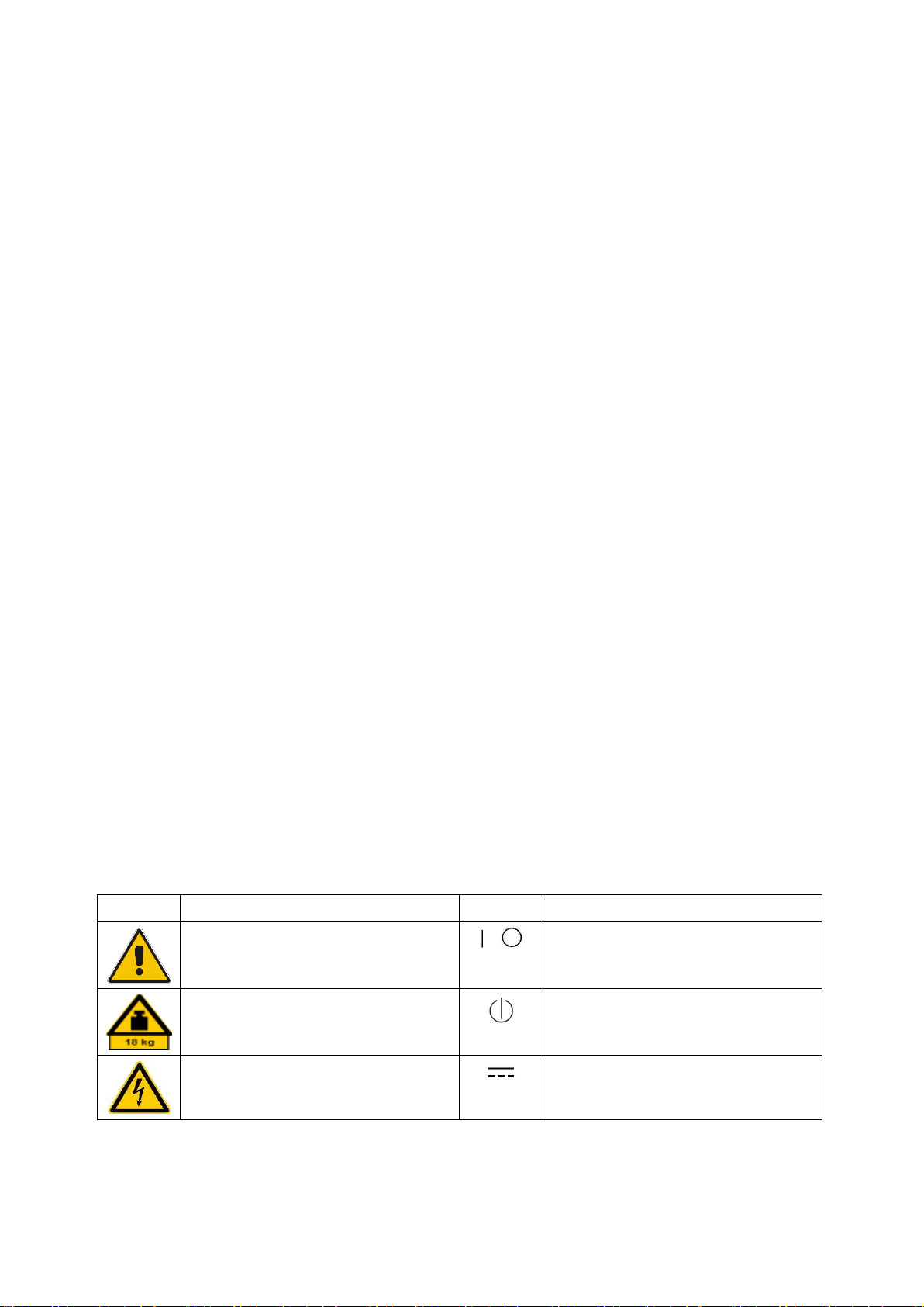
Safety labels on products
The following safety labels are used on products to warn against risks and dangers.
Symbol
Meaning
Symbol
Meaning
Notice, general danger location
Observe product documentation
ON/OFF Power
Caution when handling heavy equipment
Standby indication
Danger of electric shock
Direct current (DC)
Basic Safety Instructions
1171.0000.42 - 09 Page 2
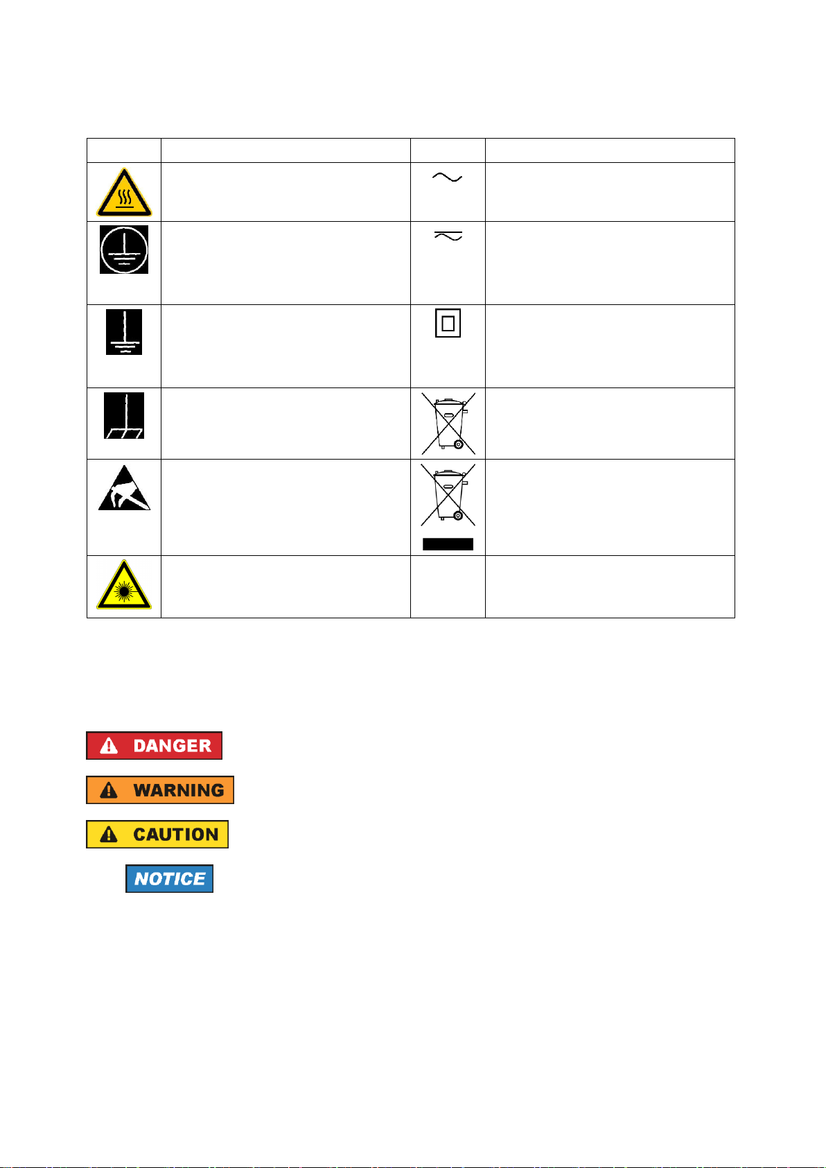
Symbol
Meaning
Symbol
Meaning
Caution ! Hot surface
Alternating current (AC)
Protective conductor terminal
To identify any terminal which is intended for
connection to an external conductor for
protection against electric shock in case of a
fault, or the terminal of a protective earth
Direct/alternating current (DC/AC)
Earth (Ground)
Class II Equipment
to identify equipment meeting the safety
requirements specified for Class II equipment
(device protected by double or reinforced
insulation)
Frame or chassis Ground terminal
EU labeling for batteries and accumulators
For additional information, see section "Waste
disposal/Environmental protection", item 1.
Be careful when handling electrostatic sensitive
devices
EU labeling for separate collection of electrical
and electronic devices
For additional information, see section "Waste
disposal/Environmental protection", item 2.
Warning! Laser radiation
For additional information, see section
"Operation", item 7.
Signal words and their meaning
The following signal words are used in the product documentation in order to warn the reader about risks
and dangers.
Indicates a hazardous situation which, if not avoided, will result in death or
serious injury.
Indicates a hazardous situation which, if not avoided, could result in death or
serious injury.
Indicates a hazardous situation which, if not avoided, could result in minor or
moderate injury.
Indicates information considered important, but not hazard-related, e.g.
messages relating to property damage.
In the product documentation, the word ATTENTION is used synonymously.
These signal words are in accordance with the standard definition for civil applications in the European
Economic Area. Definitions that deviate from the standard definition may also exist in other economic
areas or military applications. It is therefore essential to make sure that the signal words described here
are always used only in connection with the related product documentation and the related product. The
use of signal words in connection with unrelated products or documentation can result in misinterpretation
and in personal injury or material damage.

Basic Safety Instructions
1171.0000.42 - 09 Page 3
Operating states and operating positions
The product may be operated only under the operating conditions and in the positions specified by the
manufacturer, without the product's ventilation being obstructed. If the manufacturer's specifications are
not observed, this can result in electric shock, fire and/or serious personal injury or death. Applicable local
or national safety regulations and rules for the prevention of accidents must be observed in all work
performed.
1. Unless otherwise specified, the following requirements apply to Rohde & Schwarz products:
predefined operating position is always with the housing floor facing down, IP protection 2X, use only
indoors, max. operating altitude 2000 m above sea level, max. transport altitude 4500 m above sea
level. A tolerance of ±10 % shall apply to the nominal voltage and ±5 % to the nominal frequency,
overvoltage category 2, pollution degree 2.
2. Do not place the product on surfaces, vehicles, cabinets or tables that for reasons of weight or stability
are unsuitable for this purpose. Always follow the manufacturer's installation instructions when
installing the product and fastening it to objects or structures (e.g. walls and shelves). An installation
that is not carried out as described in the product documentation could result in personal injury or
even death.
3. Do not place the product on heat-generating devices such as radiators or fan heaters. The ambient
temperature must not exceed the maximum temperature specified in the product documentation or in
the data sheet. Product overheating can cause electric shock, fire and/or serious personal injury or
even death.
Electrical safety
If the information on electrical safety is not observed either at all or to the extent necessary, electric shock,
fire and/or serious personal injury or death may occur.
1. Prior to switching on the product, always ensure that the nominal voltage setting on the product
matches the nominal voltage of the mains-supply network. If a different voltage is to be set, the power
fuse of the product may have to be changed accordingly.
2. In the case of products of safety class I with movable power cord and connector, operation is
permitted only on sockets with a protective conductor contact and protective conductor.
3. Intentionally breaking the protective conductor either in the feed line or in the product itself is not
permitted. Doing so can result in the danger of an electric shock from the product. If extension cords
or connector strips are implemented, they must be checked on a regular basis to ensure that they are
safe to use.
4. If there is no power switch for disconnecting the product from the mains, or if the power switch is not
suitable for this purpose, use the plug of the connecting cable to disconnect the product from the
mains. In such cases, always ensure that the power plug is easily reachable and accessible at all
times. For example, if the power plug is the disconnecting device, the length of the connecting cable
must not exceed 3 m. Functional or electronic switches are not suitable for providing disconnection
from the AC supply network. If products without power switches are integrated into racks or systems,
the disconnecting device must be provided at the system level.
5. Never use the product if the power cable is damaged. Check the power cables on a regular basis to
ensure that they are in proper operating condition. By taking appropriate safety measures and
carefully laying the power cable, ensure that the cable cannot be damaged and that no one can be
hurt by, for example, tripping over the cable or suffering an electric shock.

Basic Safety Instructions
1171.0000.42 - 09 Page 4
6. The product may be operated only from TN/TT supply networks fuse-protected with max. 16 A (higher
fuse only after consulting with the Rohde & Schwarz group of companies).
7. Do not insert the plug into sockets that are dusty or dirty. Insert the plug firmly and all the way into the
socket provided for this purpose. Otherwise, sparks that result in fire and/or injuries may occur.
8. Do not overload any sockets, extension cords or connector strips; doing so can cause fire or electric
shocks.
9. For measurements in circuits with voltages V
rms
> 30 V, suitable measures (e.g. appropriate
measuring equipment, fuse protection, current limiting, electrical separation, insulation) should be
taken to avoid any hazards.
10. Ensure that the connections with information technology equipment, e.g. PCs or other industrial
computers, comply with the IEC 60950-1 / EN 60950-1 or IEC 61010-1 / EN 61010-1 standards that
apply in each case.
11. Unless expressly permitted, never remove the cover or any part of the housing while the product is in
operation. Doing so will expose circuits and components and can lead to injuries, fire or damage to the
product.
12. If a product is to be permanently installed, the connection between the protective conductor terminal
on site and the product's protective conductor must be made first before any other connection is
made. The product may be installed and connected only by a licensed electrician.
13. For permanently installed equipment without built-in fuses, circuit breakers or similar protective
devices, the supply circuit must be fuse-protected in such a way that anyone who has access to the
product, as well as the product itself, is adequately protected from injury or damage.
14. Use suitable overvoltage protection to ensure that no overvoltage (such as that caused by a bolt of
lightning) can reach the product. Otherwise, the person operating the product will be exposed to the
danger of an electric shock.
15. Any object that is not designed to be placed in the openings of the housing must not be used for this
purpose. Doing so can cause short circuits inside the product and/or electric shocks, fire or injuries.
16. Unless specified otherwise, products are not liquid-proof (see also section "Operating states and
operating positions", item 1). Therefore, the equipment must be protected against penetration by
liquids. If the necessary precautions are not taken, the user may suffer electric shock or the product
itself may be damaged, which can also lead to personal injury.
17. Never use the product under conditions in which condensation has formed or can form in or on the
product, e.g. if the product has been moved from a cold to a warm environment. Penetration by water
increases the risk of electric shock.
18. Prior to cleaning the product, disconnect it completely from the power supply (e.g. AC supply network
or battery). Use a soft, non-linting cloth to clean the product. Never use chemical cleaning agents such
as alcohol, acetone or diluents for cellulose lacquers.
Operation
1. Operating the products requires special training and intense concentration. Make sure that persons
who use the products are physically, mentally and emotionally fit enough to do so; otherwise, injuries
or material damage may occur. It is the responsibility of the employer/operator to select suitable
personnel for operating the products.

Basic Safety Instructions
1171.0000.42 - 09 Page 5
2. Before you move or transport the product, read and observe the section titled "Transport".
3. As with all industrially manufactured goods, the use of substances that induce an allergic reaction
(allergens) such as nickel cannot be generally excluded. If you develop an allergic reaction (such as a
skin rash, frequent sneezing, red eyes or respiratory difficulties) when using a Rohde & Schwarz
product, consult a physician immediately to determine the cause and to prevent health problems or
stress.
4. Before you start processing the product mechanically and/or thermally, or before you take it apart, be
sure to read and pay special attention to the section titled "Waste disposal/Environmental protection",
item 1.
5. Depending on the function, certain products such as RF radio equipment can produce an elevated
level of electromagnetic radiation. Considering that unborn babies require increased protection,
pregnant women must be protected by appropriate measures. Persons with pacemakers may also be
exposed to risks from electromagnetic radiation. The employer/operator must evaluate workplaces
where there is a special risk of exposure to radiation and, if necessary, take measures to avert the
potential danger.
6. Should a fire occur, the product may release hazardous substances (gases, fluids, etc.) that can
cause health problems. Therefore, suitable measures must be taken, e.g. protective masks and
protective clothing must be worn.
7. Laser products are given warning labels that are standardized according to their laser class. Lasers
can cause biological harm due to the properties of their radiation and due to their extremely
concentrated electromagnetic power. If a laser product (e.g. a CD/DVD drive) is integrated into a
Rohde & Schwarz product, absolutely no other settings or functions may be used as described in the
product documentation. The objective is to prevent personal injury (e.g. due to laser beams).
8. EMC classes (in line with EN 55011/CISPR 11, and analogously with EN 55022/CISPR 22,
EN 55032/CISPR 32)
Class A equipment:
Equipment suitable for use in all environments except residential environments and environments
that are directly connected to a low-voltage supply network that supplies residential buildings
Note: Class A equipment is intended for use in an industrial environment. This equipment may
cause radio disturbances in residential environments, due to possible conducted as well as
radiated disturbances. In this case, the operator may be required to take appropriate measures to
eliminate these disturbances.
Class B equipment:
Equipment suitable for use in residential environments and environments that are directly
connected to a low-voltage supply network that supplies residential buildings
Repair and service
1. The product may be opened only by authorized, specially trained personnel. Before any work is
performed on the product or before the product is opened, it must be disconnected from the AC supply
network. Otherwise, personnel will be exposed to the risk of an electric shock.

Basic Safety Instructions
1171.0000.42 - 09 Page 6
2. Adjustments, replacement of parts, maintenance and repair may be performed only by electrical
experts authorized by Rohde & Schwarz. Only original parts may be used for replacing parts relevant
to safety (e.g. power switches, power transformers, fuses). A safety test must always be performed
after parts relevant to safety have been replaced (visual inspection, protective conductor test,
insulation resistance measurement, leakage current measurement, functional test). This helps ensure
the continued safety of the product.
Batteries and rechargeable batteries/cells
If the information regarding batteries and rechargeable batteries/cells is not observed either at all or to the
extent necessary, product users may be exposed to the risk of explosions, fire and/or serious personal
injury, and, in some cases, death. Batteries and rechargeable batteries with alkaline electrolytes (e.g.
lithium cells) must be handled in accordance with the EN 62133 standard.
1. Cells must not be taken apart or crushed.
2. Cells or batteries must not be exposed to heat or fire. Storage in direct sunlight must be avoided.
Keep cells and batteries clean and dry. Clean soiled connectors using a dry, clean cloth.
3. Cells or batteries must not be short-circuited. Cells or batteries must not be stored in a box or in a
drawer where they can short-circuit each other, or where they can be short-circuited by other
conductive materials. Cells and batteries must not be removed from their original packaging until they
are ready to be used.
4. Cells and batteries must not be exposed to any mechanical shocks that are stronger than permitted.
5. If a cell develops a leak, the fluid must not be allowed to come into contact with the skin or eyes. If
contact occurs, wash the affected area with plenty of water and seek medical aid.
6. Improperly replacing or charging cells or batteries that contain alkaline electrolytes (e.g. lithium cells)
can cause explosions. Replace cells or batteries only with the matching Rohde & Schwarz type (see
parts list) in order to ensure the safety of the product.
7. Cells and batteries must be recycled and kept separate from residual waste. Rechargeable batteries
and normal batteries that contain lead, mercury or cadmium are hazardous waste. Observe the
national regulations regarding waste disposal and recycling.
8. Follow the transport stipulations of the carrier (IATA-DGR, IMDG-Code, ADR, RID) when returning
lithium batteries to Rohde & Schwarz subsidiaries.
Transport
1. The product may be very heavy. Therefore, the product must be handled with care. In some cases,
the user may require a suitable means of lifting or moving the product (e.g. with a lift-truck) to avoid
back or other physical injuries.
2. Handles on the products are designed exclusively to enable personnel to transport the product. It is
therefore not permissible to use handles to fasten the product to or on transport equipment such as
cranes, fork lifts, wagons, etc. The user is responsible for securely fastening the products to or on the
means of transport or lifting. Observe the safety regulations of the manufacturer of the means of
transport or lifting. Noncompliance can result in personal injury or material damage.

Basic Safety Instructions
1171.0000.42 - 09 Page 7
3. If you use the product in a vehicle, it is the sole responsibility of the driver to drive the vehicle safely
and properly. The manufacturer assumes no responsibility for accidents or collisions. Never use the
product in a moving vehicle if doing so could distract the driver of the vehicle. Adequately secure the
product in the vehicle to prevent injuries or other damage in the event of an accident.
Waste disposal/Environmental protection
1. Specially marked equipment has a battery or accumulator that must not be disposed of with unsorted
municipal waste, but must be collected separately. It may only be disposed of at a suitable collection
point or via a Rohde & Schwarz customer service center.
2. Waste electrical and electronic equipment must not be disposed of with unsorted municipal waste, but
must be collected separately.
Rohde & Schwarz GmbH & Co. KG has developed a disposal concept and takes full responsibility for
take-back obligations and disposal obligations for manufacturers within the EU. Contact your
Rohde & Schwarz customer service center for environmentally responsible disposal of the product.
3. If products or their components are mechanically and/or thermally processed in a manner that goes
beyond their intended use, hazardous substances (heavy-metal dust such as lead, beryllium, nickel)
may be released. For this reason, the product may only be disassembled by specially trained
personnel. Improper disassembly may be hazardous to your health. National waste disposal
regulations must be observed.
4. If handling the product releases hazardous substances or fuels that must be disposed of in a special
way, e.g. coolants or engine oils that must be replenished regularly, the safety instructions of the
manufacturer of the hazardous substances or fuels and the applicable regional waste disposal
regulations must be observed. Also observe the relevant safety instructions in the product
documentation. The improper disposal of hazardous substances or fuels can cause health problems
and lead to environmental damage.
For additional information about environmental protection, visit the Rohde & Schwarz website.

Instrucciones de seguridad elementales
1171.0000.42 - 09 Page 8
Instrucciones de seguridad elementales
¡Es imprescindible leer y cumplir las siguientes instrucciones e informaciones de seguridad!
El principio del grupo de empresas Rohde & Schwarz consiste en tener nuestros productos siempre al día
con los estándares de seguridad y de ofrecer a nuestros clientes el máximo grado de seguridad. Nuestros
productos y todos los equipos adicionales son siempre fabricados y examinados según las normas de
seguridad vigentes. Nuestro sistema de garantía de calidad controla constantemente que sean cumplidas
estas normas. El presente producto ha sido fabricado y examinado según el certificado de conformidad
de la UE y ha salido de nuestra planta en estado impecable según los estándares técnicos de seguridad.
Para poder preservar este estado y garantizar un funcionamiento libre de peligros, el usuario deberá
atenerse a todas las indicaciones, informaciones de seguridad y notas de alerta. El grupo de empresas
Rohde & Schwarz está siempre a su disposición en caso de que tengan preguntas referentes a estas
informaciones de seguridad.
Además queda en la responsabilidad del usuario utilizar el producto en la forma debida. Este producto
está destinado exclusivamente al uso en la industria y el laboratorio o, si ha sido expresamente
autorizado, para aplicaciones de campo y de ninguna manera deberá ser utilizado de modo que alguna
persona/cosa pueda sufrir daño. El uso del producto fuera de sus fines definidos o sin tener en cuenta las
instrucciones del fabricante queda en la responsabilidad del usuario. El fabricante no se hace en ninguna
forma responsable de consecuencias a causa del mal uso del producto.
Se parte del uso correcto del producto para los fines definidos si el producto es utilizado conforme a las
indicaciones de la correspondiente documentación del producto y dentro del margen de rendimiento
definido (ver hoja de datos, documentación, informaciones de seguridad que siguen). El uso del producto
hace necesarios conocimientos técnicos y ciertos conocimientos del idioma inglés. Por eso se debe tener
en cuenta que el producto solo pueda ser operado por personal especializado o personas instruidas en
profundidad con las capacidades correspondientes. Si fuera necesaria indumentaria de seguridad para el
uso de productos de Rohde & Schwarz, encontraría la información debida en la documentación del
producto en el capítulo correspondiente. Guarde bien las informaciones de seguridad elementales, así
como la documentación del producto, y entréguelas a usuarios posteriores.
Tener en cuenta las informaciones de seguridad sirve para evitar en lo posible lesiones o daños por
peligros de toda clase. Por eso es imprescindible leer detalladamente y comprender por completo las
siguientes informaciones de seguridad antes de usar el producto, y respetarlas durante el uso del
producto. Deberán tenerse en cuenta todas las demás informaciones de seguridad, como p. ej. las
referentes a la protección de personas, que encontrarán en el capítulo correspondiente de la
documentación del producto y que también son de obligado cumplimiento. En las presentes
informaciones de seguridad se recogen todos los objetos que distribuye el grupo de empresas
Rohde & Schwarz bajo la denominación de "producto", entre ellos también aparatos, instalaciones así
como toda clase de accesorios. Los datos específicos del producto figuran en la hoja de datos y en la
documentación del producto.
Instrucciones de seguridad elementales
1171.0000.42 - 09 Page 9
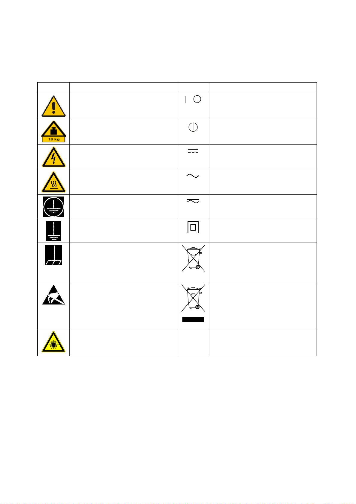
Señalización de seguridad de los productos
Las siguientes señales de seguridad se utilizan en los productos para advertir sobre riesgos y peligros.
Símbolo
Significado
Símbolo
Significado
Aviso: punto de peligro general
Observar la documentación del producto
Tensión de alimentación de PUESTA EN
MARCHA / PARADA
Atención en el manejo de dispositivos de peso
elevado
Indicación de estado de espera (standby)
Peligro de choque eléctrico
Corriente continua (DC)
Advertencia: superficie caliente
Corriente alterna (AC)
Conexión a conductor de protección
Corriente continua / Corriente alterna (DC/AC)
Conexión a tierra
El aparato está protegido en su totalidad por un
aislamiento doble (reforzado)
Conexión a masa
Distintivo de la UE para baterías y
acumuladores
Más información en la sección
"Eliminación/protección del medio ambiente",
punto 1.
Aviso: Cuidado en el manejo de dispositivos
sensibles a la electrostática (ESD)
Distintivo de la UE para la eliminación por
separado de dispositivos eléctricos y
electrónicos
Más información en la sección
"Eliminación/protección del medio ambiente",
punto 2.
Advertencia: rayo láser
Más información en la sección
"Funcionamiento", punto 7.

Instrucciones de seguridad elementales
1171.0000.42 - 09 Page 10
Palabras de señal y su significado
En la documentación del producto se utilizan las siguientes palabras de señal con el fin de advertir contra
riesgos y peligros.
Indica una situación de peligro que, si no se evita, causa lesiones
graves o incluso la muerte.
Indica una situación de peligro que, si no se evita, puede causar
lesiones graves o incluso la muerte.
Indica una situación de peligro que, si no se evita, puede causar
lesiones leves o moderadas.
Indica información que se considera importante, pero no en relación
con situaciones de peligro; p. ej., avisos sobre posibles daños
materiales.
En la documentación del producto se emplea de forma sinónima el
término CUIDADO.
Las palabras de señal corresponden a la definición habitual para aplicaciones civiles en el área
económica europea. Pueden existir definiciones diferentes a esta definición en otras áreas económicas o
en aplicaciones militares. Por eso se deberá tener en cuenta que las palabras de señal aquí descritas
sean utilizadas siempre solamente en combinación con la correspondiente documentación del producto y
solamente en combinación con el producto correspondiente. La utilización de las palabras de señal en
combinación con productos o documentaciones que no les correspondan puede llevar a interpretaciones
equivocadas y tener por consecuencia daños en personas u objetos.
Estados operativos y posiciones de funcionamiento
El producto solamente debe ser utilizado según lo indicado por el fabricante respecto a los estados
operativos y posiciones de funcionamiento sin que se obstruya la ventilación. Si no se siguen las
indicaciones del fabricante, pueden producirse choques eléctricos, incendios y/o lesiones graves con
posible consecuencia de muerte. En todos los trabajos deberán ser tenidas en cuenta las normas
nacionales y locales de seguridad del trabajo y de prevención de accidentes.
1. Si no se convino de otra manera, es para los productos Rohde & Schwarz válido lo que sigue:
como posición de funcionamiento se define por principio la posición con el suelo de la caja para
abajo, modo de protección IP 2X, uso solamente en estancias interiores, utilización hasta 2000 m
sobre el nivel del mar, transporte hasta 4500 m sobre el nivel del mar. Se aplicará una tolerancia de
±10 % sobre el voltaje nominal y de ±5 % sobre la frecuencia nominal. Categoría de sobrecarga
eléctrica 2, índice de suciedad 2.
2. No sitúe el producto encima de superficies, vehículos, estantes o mesas, que por sus características
de peso o de estabilidad no sean aptos para él. Siga siempre las instrucciones de instalación del
fabricante cuando instale y asegure el producto en objetos o estructuras (p. ej. paredes y estantes). Si
se realiza la instalación de modo distinto al indicado en la documentación del producto, se pueden
causar lesiones o, en determinadas circunstancias, incluso la muerte.
3. No ponga el producto sobre aparatos que generen calor (p. ej. radiadores o calefactores). La
temperatura ambiente no debe superar la temperatura máxima especificada en la documentación del
producto o en la hoja de datos. En caso de sobrecalentamiento del producto, pueden producirse
choques eléctricos, incendios y/o lesiones graves con posible consecuencia de muerte.

Instrucciones de seguridad elementales
1171.0000.42 - 09 Page 11
Seguridad eléctrica
Si no se siguen (o se siguen de modo insuficiente) las indicaciones del fabricante en cuanto a seguridad
eléctrica, pueden producirse choques eléctricos, incendios y/o lesiones graves con posible consecuencia
de muerte.
1. Antes de la puesta en marcha del producto se deberá comprobar siempre que la tensión
preseleccionada en el producto coincida con la de la red de alimentación eléctrica. Si es necesario
modificar el ajuste de tensión, también se deberán cambiar en caso dado los fusibles
correspondientes del producto.
2. Los productos de la clase de protección I con alimentación móvil y enchufe individual solamente
podrán enchufarse a tomas de corriente con contacto de seguridad y con conductor de protección
conectado.
3. Queda prohibida la interrupción intencionada del conductor de protección, tanto en la toma de
corriente como en el mismo producto. La interrupción puede tener como consecuencia el riesgo de
que el producto sea fuente de choques eléctricos. Si se utilizan cables alargadores o regletas de
enchufe, deberá garantizarse la realización de un examen regular de los mismos en cuanto a su
estado técnico de seguridad.
4. Si el producto no está equipado con un interruptor para desconectarlo de la red, o bien si el
interruptor existente no resulta apropiado para la desconexión de la red, el enchufe del cable de
conexión se deberá considerar como un dispositivo de desconexión.
El dispositivo de desconexión se debe poder alcanzar fácilmente y debe estar siempre bien accesible.
Si, p. ej., el enchufe de conexión a la red es el dispositivo de desconexión, la longitud del cable de
conexión no debe superar 3 m).
Los interruptores selectores o electrónicos no son aptos para el corte de la red eléctrica. Si se
integran productos sin interruptor en bastidores o instalaciones, se deberá colocar el interruptor en el
nivel de la instalación.
5. No utilice nunca el producto si está dañado el cable de conexión a red. Compruebe regularmente el
correcto estado de los cables de conexión a red. Asegúrese, mediante las medidas de protección y
de instalación adecuadas, de que el cable de conexión a red no pueda ser dañado o de que nadie
pueda ser dañado por él, p. ej. al tropezar o por un choque eléctrico.
6. Solamente está permitido el funcionamiento en redes de alimentación TN/TT aseguradas con fusibles
de 16 A como máximo (utilización de fusibles de mayor amperaje solo previa consulta con el grupo de
empresas Rohde & Schwarz).
7. Nunca conecte el enchufe en tomas de corriente sucias o llenas de polvo. Introduzca el enchufe por
completo y fuertemente en la toma de corriente. La no observación de estas medidas puede provocar
chispas, fuego y/o lesiones.
8. No sobrecargue las tomas de corriente, los cables alargadores o las regletas de enchufe ya que esto
podría causar fuego o choques eléctricos.
9. En las mediciones en circuitos de corriente con una tensión U
eff
> 30 V se deberán tomar las medidas
apropiadas para impedir cualquier peligro (p. ej. medios de medición adecuados, seguros, limitación
de tensión, corte protector, aislamiento etc.).
10. Para la conexión con dispositivos informáticos como un PC o un ordenador industrial, debe
comprobarse que éstos cumplan los estándares IEC60950-1/EN60950-1 o IEC61010-1/EN 61010-1
válidos en cada caso.

Instrucciones de seguridad elementales
1171.0000.42 - 09 Page 12
11. A menos que esté permitido expresamente, no retire nunca la tapa ni componentes de la carcasa
mientras el producto esté en servicio. Esto pone a descubierto los cables y componentes eléctricos y
puede causar lesiones, fuego o daños en el producto.
12. Si un producto se instala en un lugar fijo, se deberá primero conectar el conductor de protección fijo
con el conductor de protección del producto antes de hacer cualquier otra conexión. La instalación y
la conexión deberán ser efectuadas por un electricista especializado.
13. En el caso de dispositivos fijos que no estén provistos de fusibles, interruptor automático ni otros
mecanismos de seguridad similares, el circuito de alimentación debe estar protegido de modo que
todas las personas que puedan acceder al producto, así como el producto mismo, estén a salvo de
posibles daños.
14. Todo producto debe estar protegido contra sobretensión (debida p. ej. a una caída del rayo) mediante
los correspondientes sistemas de protección. Si no, el personal que lo utilice quedará expuesto al
peligro de choque eléctrico.
15. No debe introducirse en los orificios de la caja del aparato ningún objeto que no esté destinado a ello.
Esto puede producir cortocircuitos en el producto y/o puede causar choques eléctricos, fuego o
lesiones.
16. Salvo indicación contraria, los productos no están impermeabilizados (ver también el capítulo
"Estados operativos y posiciones de funcionamiento", punto 1). Por eso es necesario tomar las
medidas necesarias para evitar la entrada de líquidos. En caso contrario, existe peligro de choque
eléctrico para el usuario o de daños en el producto, que también pueden redundar en peligro para las
personas.
17. No utilice el producto en condiciones en las que pueda producirse o ya se hayan producido
condensaciones sobre el producto o en el interior de éste, como p. ej. al desplazarlo de un lugar frío a
otro caliente. La entrada de agua aumenta el riesgo de choque eléctrico.
18. Antes de la limpieza, desconecte por completo el producto de la alimentación de tensión (p. ej. red de
alimentación o batería). Realice la limpieza de los aparatos con un paño suave, que no se deshilache.
No utilice bajo ningún concepto productos de limpieza químicos como alcohol, acetona o diluyentes
para lacas nitrocelulósicas.
Funcionamiento
1. El uso del producto requiere instrucciones especiales y una alta concentración durante el manejo.
Debe asegurarse que las personas que manejen el producto estén a la altura de los requerimientos
necesarios en cuanto a aptitudes físicas, psíquicas y emocionales, ya que de otra manera no se
pueden excluir lesiones o daños de objetos. El empresario u operador es responsable de seleccionar
el personal usuario apto para el manejo del producto.
2. Antes de desplazar o transportar el producto, lea y tenga en cuenta el capítulo "Transporte".
3. Como con todo producto de fabricación industrial no puede quedar excluida en general la posibilidad
de que se produzcan alergias provocadas por algunos materiales empleados ―los llamados
alérgenos (p. ej. el níquel)―. Si durante el manejo de productos Rohde & Schwarz se producen
reacciones alérgicas, como p. ej. irritaciones cutáneas, estornudos continuos, enrojecimiento de la
conjuntiva o dificultades respiratorias, debe avisarse inmediatamente a un médico para investigar las
causas y evitar cualquier molestia o daño a la salud.
4. Antes de la manipulación mecánica y/o térmica o el desmontaje del producto, debe tenerse en cuenta
imprescindiblemente el capítulo "Eliminación/protección del medio ambiente", punto 1.

Instrucciones de seguridad elementales
1171.0000.42 - 09 Page 13
5. Ciertos productos, como p. ej. las instalaciones de radiocomunicación RF, pueden a causa de su
función natural, emitir una radiación electromagnética aumentada. Deben tomarse todas las medidas
necesarias para la protección de las mujeres embarazadas. También las personas con marcapasos
pueden correr peligro a causa de la radiación electromagnética. El empresario/operador tiene la
obligación de evaluar y señalizar las áreas de trabajo en las que exista un riesgo elevado de
exposición a radiaciones.
6. Tenga en cuenta que en caso de incendio pueden desprenderse del producto sustancias tóxicas
(gases, líquidos etc.) que pueden generar daños a la salud. Por eso, en caso de incendio deben
usarse medidas adecuadas, como p. ej. máscaras antigás e indumentaria de protección.
7. Los productos con láser están provistos de indicaciones de advertencia normalizadas en función de la
clase de láser del que se trate. Los rayos láser pueden provocar daños de tipo biológico a causa de
las propiedades de su radiación y debido a su concentración extrema de potencia electromagnética.
En caso de que un producto Rohde & Schwarz contenga un producto láser (p. ej. un lector de
CD/DVD), no debe usarse ninguna otra configuración o función aparte de las descritas en la
documentación del producto, a fin de evitar lesiones (p. ej. debidas a irradiación láser).
8. Clases de compatibilidad electromagnética (conforme a EN 55011 / CISPR 11; y en analogía con EN
55022 / CISPR 22, EN 55032 / CISPR 32)
Aparato de clase A:
Aparato adecuado para su uso en todos los entornos excepto en los residenciales y en aquellos
conectados directamente a una red de distribución de baja tensión que suministra corriente a
edificios residenciales.
Nota: Los aparatos de clase A están destinados al uso en entornos industriales. Estos aparatos
pueden causar perturbaciones radioeléctricas en entornos residenciales debido a posibles
perturbaciones guiadas o radiadas. En este caso, se le podrá solicitar al operador que tome las
medidas adecuadas para eliminar estas perturbaciones.
Aparato de clase B:
Aparato adecuado para su uso en entornos residenciales, así como en aquellos conectados
directamente a una red de distribución de baja tensión que suministra corriente a edificios
residenciales.
Reparación y mantenimiento
1. El producto solamente debe ser abierto por personal especializado con autorización para ello. Antes
de manipular el producto o abrirlo, es obligatorio desconectarlo de la tensión de alimentación, para
evitar toda posibilidad de choque eléctrico.
2. El ajuste, el cambio de partes, el mantenimiento y la reparación deberán ser efectuadas solamente
por electricistas autorizados por Rohde & Schwarz. Si se reponen partes con importancia para los
aspectos de seguridad (p. ej. el enchufe, los transformadores o los fusibles), solamente podrán ser
sustituidos por partes originales. Después de cada cambio de partes relevantes para la seguridad
deberá realizarse un control de seguridad (control a primera vista, control del conductor de
protección, medición de resistencia de aislamiento, medición de la corriente de fuga, control de
funcionamiento). Con esto queda garantizada la seguridad del producto.

Instrucciones de seguridad elementales
1171.0000.42 - 09 Page 14
Baterías y acumuladores o celdas
Si no se siguen (o se siguen de modo insuficiente) las indicaciones en cuanto a las baterías y
acumuladores o celdas, pueden producirse explosiones, incendios y/o lesiones graves con posible
consecuencia de muerte. El manejo de baterías y acumuladores con electrolitos alcalinos (p. ej. celdas de
litio) debe seguir el estándar EN 62133.
1. No deben desmontarse, abrirse ni triturarse las celdas.
2. Las celdas o baterías no deben someterse a calor ni fuego. Debe evitarse el almacenamiento a la luz
directa del sol. Las celdas y baterías deben mantenerse limpias y secas. Limpiar las conexiones
sucias con un paño seco y limpio.
3. Las celdas o baterías no deben cortocircuitarse. Es peligroso almacenar las celdas o baterías en
estuches o cajones en cuyo interior puedan cortocircuitarse por contacto recíproco o por contacto con
otros materiales conductores. No deben extraerse las celdas o baterías de sus embalajes originales
hasta el momento en que vayan a utilizarse.
4. Las celdas o baterías no deben someterse a impactos mecánicos fuertes indebidos.
5. En caso de falta de estanqueidad de una celda, el líquido vertido no debe entrar en contacto con la
piel ni los ojos. Si se produce contacto, lavar con agua abundante la zona afectada y avisar a un
médico.
6. En caso de cambio o recarga inadecuados, las celdas o baterías que contienen electrolitos alcalinos
(p. ej. las celdas de litio) pueden explotar. Para garantizar la seguridad del producto, las celdas o
baterías solo deben ser sustituidas por el tipo Rohde & Schwarz correspondiente (ver lista de
recambios).
7. Las baterías y celdas deben reciclarse y no deben tirarse a la basura doméstica. Las baterías o
acumuladores que contienen plomo, mercurio o cadmio deben tratarse como residuos especiales.
Respete en esta relación las normas nacionales de eliminación y reciclaje.
8. En caso de devolver baterías de litio a las filiales de Rohde & Schwarz, debe cumplirse las
normativas sobre los modos de transporte (IATA-DGR, código IMDG, ADR, RID).
Transporte
1. El producto puede tener un peso elevado. Por eso es necesario desplazarlo o transportarlo con
precaución y, si es necesario, usando un sistema de elevación adecuado (p. ej. una carretilla
elevadora), a fin de evitar lesiones en la espalda u otros daños personales.
2. Las asas instaladas en los productos sirven solamente de ayuda para el transporte del producto por
personas. Por eso no está permitido utilizar las asas para la sujeción en o sobre medios de transporte
como p. ej. grúas, carretillas elevadoras de horquilla, carros etc. Es responsabilidad suya fijar los
productos de manera segura a los medios de transporte o elevación. Para evitar daños personales o
daños en el producto, siga las instrucciones de seguridad del fabricante del medio de transporte o
elevación utilizado.
3. Si se utiliza el producto dentro de un vehículo, recae de manera exclusiva en el conductor la
responsabilidad de conducir el vehículo de manera segura y adecuada. El fabricante no asumirá
ninguna responsabilidad por accidentes o colisiones. No utilice nunca el producto dentro de un
vehículo en movimiento si esto pudiera distraer al conductor. Asegure el producto dentro del vehículo
debidamente para evitar, en caso de un accidente, lesiones u otra clase de daños.

Instrucciones de seguridad elementales
1171.0000.42 - 09 Page 15
Eliminación/protección del medio ambiente
1. Los dispositivos marcados contienen una batería o un acumulador que no se debe desechar con los
residuos domésticos sin clasificar, sino que debe ser recogido por separado. La eliminación se debe
efectuar exclusivamente a través de un punto de recogida apropiado o del servicio de atención al
cliente de Rohde & Schwarz.
2. Los dispositivos eléctricos usados no se deben desechar con los residuos domésticos sin clasificar,
sino que deben ser recogidos por separado.
Rohde & Schwarz GmbH & Co.KG ha elaborado un concepto de eliminación de residuos y asume
plenamente los deberes de recogida y eliminación para los fabricantes dentro de la UE. Para
desechar el producto de manera respetuosa con el medio ambiente, diríjase a su servicio de atención
al cliente de Rohde & Schwarz.
3. Si se trabaja de manera mecánica y/o térmica cualquier producto o componente más allá del
funcionamiento previsto, pueden liberarse sustancias peligrosas (polvos con contenido de metales
pesados como p. ej. plomo, berilio o níquel). Por eso el producto solo debe ser desmontado por
personal especializado con formación adecuada. Un desmontaje inadecuado puede ocasionar daños
para la salud. Se deben tener en cuenta las directivas nacionales referentes a la eliminación de
residuos.
4. En caso de que durante el trato del producto se formen sustancias peligrosas o combustibles que
deban tratarse como residuos especiales (p. ej. refrigerantes o aceites de motor con intervalos de
cambio definidos), deben tenerse en cuenta las indicaciones de seguridad del fabricante de dichas
sustancias y las normas regionales de eliminación de residuos. Tenga en cuenta también en caso
necesario las indicaciones de seguridad especiales contenidas en la documentación del producto. La
eliminación incorrecta de sustancias peligrosas o combustibles puede causar daños a la salud o
daños al medio ambiente.
Se puede encontrar más información sobre la protección del medio ambiente en la página web de
Rohde & Schwarz.

Customer Support
Technical support – where and when you need it
For quick, expert help with any Rohde & Schwarz equipment, contact one of our Customer Support
Centers. A team of highly qualified engineers provides telephone support and will work with you to find a
solution to your query on any aspect of the operation, programming or applications of Rohde & Schwarz
equipment.
Up-to-date information and upgrades
To keep your instrument up-to-date and to be informed about new application notes related to your
instrument, please send an e-mail to the Customer Support Center stating your instrument and your wish.
We will take care that you will get the right information.
Europe, Africa, Middle East
North America
Latin America
Asia/Pacific
China
Phone +49 89 4129 12345
customersupport@rohde-schwarz.com
Phone 1-888-TEST-RSA (1-888-837-8772)
customer.support@rsa.rohde-schwarz.com
Phone +1-410-910-7988
customersupport.la@rohde-schwarz.com
Phone +65 65 13 04 88
customersupport.asia@rohde-schwarz.com
Phone +86-800-810-8228 /
+86-400-650-5896
customersupport.china@rohde-schwarz.com
1171.0200.22-06.00
R&S ZVL R&S ZVL Documentation Map
R&S ZVL Documentation Map
Standard Documentation
The following documentation is supplied with the instrument.
The help systems are embedded in the instrument, offering quick,
context-sensitive reference to the information needed for
operation and programming. The help systems contain the
complete user documentation for the network analyzer including
all optional features. The instrument provides two help files for the
network analyzer modes and for the spectrum analyzer mode.
You can also transfer the help files RSZVLhelp.chm (network
analyzer mode plus basic functions) and RSFSLhelp.chm
(spectrum analyzer mode plus supplementary spectrum analyzer
options) to your PC and use them as standalone help files.
The quick start guide contains the data sheet (“Product Brochure”
and “Specifications”), describes everything that is needed to put
the instrument into operation and helps you get familiar with the
analyzer. The quick start guide gives an introduction to the
instrument’s functionality and provides procedures for typical
measurement tasks.
For an overview and a short description of R&S ZVL options refer
to section “Optional Extensions” in the “System Overview” chapter
at the end of the quick start guide.
The CD-ROM provides the complete user documentation for the
network analyzer:
= The online help system in two different HTML-based formats
(*.chm for transfer to the hard disk and WebHelp for viewing
from the CD).
= Printable (*.pdf) versions of the online help systems. The R&S
ZVL operating manual describes the R&S ZVL instrument
including network analyzer mode. A separate manual
describes the spectrum analyzer mode (with option R&S ZVLK1) and the supplementary spectrum analyzer options.
= The quick start manual in printable form.
= The service manual in printable form.
= Links to different useful sites in the R&S internet.
Quick Start Guide 1303.6538.62 - 06 3

R&S ZVL Glossary of Terms
Glossary of Terms
A
Active channel: Channel belonging to the active trace. The active channel is
highlighted in the channel list below the diagram. The active channel is not relevant in
remote control where each channel can contain an active trace.
Active marker: Marker that can be changed using the settings of the Marker menu
(Delta Mode, Ref. Mkr -> Mkr, Mkr Format). The active marker is also used for the
Marker Functions. It appears in the diagram with an enlarged marker symbol and font
size and with a dot placed in front of the marker line in the info field.
Active menu: The menu containing the last executed command. If the softkey bar is
displayed (Display - Config./View - Softkey Labels on), then the active menu is
indicated on top of the softkey bar.
Active trace (manual control): Trace that is selected to apply the settings in the
Trace menu. The active trace is highlighted in the trace list of the active diagram area.
It can be different from the active trace in remote control.
Active trace (remote control): One trace of each channel that has been selected as
the active trace (CALCulate[Ch]:PARameter:SELect <Trace Name>). Many commands
(e.g. TRACE...) act on the active trace. It can be different from the active trace in
manual control.
C
Cal pool: The cal pool is a collection of correction data sets (cal groups) that the
analyzer stores in a common directory. Cal groups in the pool can beapplied to
different channels and setups.
Calibration: The process of removing systematic errors from the measurement
(system error correction). See also TOSM, TOM, TRM, TRL, TNA.
Calibration kit: Set of physical calibration standards for a particular connector family.
Calibration standard: Physical device that has a known or predictable magnitude and
phase response within a given frequency range. Calibration standards are grouped into
several types (open, through, match,...) corresponding to the different input quantities
for the analyzer's error models.
Calibration unit: Integrated solution for automatic calibration of 1 to 4 ports
(accessory ZV-Z41). The unit contains calibration standards that are electronically
switched when a calibration is performed.
Channel: A channel contains hardware-related settings to specify how the network
analyzer collects data. Each channel is stored in an independent data set. The channel
settings complement the definitions of the Trace menu; they apply to all traces
assigned to the channel.
Confirmation dialog box: Standard dialog box that pops up to display an error
message or a warning. The current action can be either continued (OK) or cancelled
(Cancel) on closing the dialog box.
Quick Start Guide 1303.6538.62 - 05
4

R&S ZVL Glossary of Terms
Crosstalk: The occurr
travel through the test setup and the DUT but leaks through other internal paths.
Crosstalk causes an isolation error in the measurement which can be corrected by
means of a calibration.
ence of a signal at the receive port of the analyzer which did not
D
Data trace: Trace filled with measurement data and updated after each sweep
(dynamic trace).
Diagram area: Rectangular portion of the screen used to display traces. Diagram
areas are arranged in windows; they are independent of trace and channel settings.
Directivity error: Measurement error caused by a coupler or bridge in the analyzer's
source port causing part of the generated signal to leak through the forward path into
the receive path instead of being transmitted towards the DUT. The directivity error can
be corrected by means of a full one port calibration or one of the two-port calibration
methods (except normalization).
Discrete marker: The stimulus value of a discrete marker always coincides with a
sweep point so that the marker does not show interpolated measurement values.
E
Excursion: Difference between the response values at a local maximum (minimum) of
the trace and at the two closest local minima (maxima) to the left and to the right.
F
Forward: A measurement on a two-port DUT is said to be in forward direction if the
source signal (stimulus) is applied to port 1 of the DUT.
I
Isolation error: Measurement error caused by a crosstalk between the source and
receive port of the analyzer.
L
Limit check: Comparison of the measurement results with the limit lines and display of
a pass/fail indication.
Limit line: A limit line is a set of data to specify the allowed range for some or all
points of a trace. Typically, limit lines are used to check whether a DUT conforms to
the rated specifications (conformance testing).
Load match error: Measurement error caused by a mismatch of the analyzer's
receive (load) port causing part of the signal transmitted through the DUT to be
reflected off the receive port so that it is not measured there. The load match error can
be corrected by means of a two-port calibration (except normalization).
M
Marker: Tool for selecting points on the trace and for numerical readout of measured
data. A marker is displayed with a symbol (a triangle, a crossbar or a line) on the trace;
its coordinates are shown in the marker info field.
Quick Start Guide 1303.6538.62 - 05
5

R&S ZVL Glossary of Terms
Mathematical trace: Trace that
e.g. the one defined in the Define Math dialog. The expression is a mathematical
relation between constants and the data or memory traces of the active setup.
Measurement point: Result of the measurement at a specified stimulus value
(frequency/power/time).
Measurement result: Set of all measurement points acquired in a measurement (e.g.
a sweep). The measurement result is displayed in a diagram area and forms a trace.
Memory trace: Trace that is associated to a data trace and stored in the memory.
Data traces and the associated memory traces share the same channel and scale
settings. Alternatively, memory traces can be imported from a file.
is calculated according to a mathematical expression,
P
Partial measurement: Measurement at a specified stimulus value maintaining definite
hardware settings. Depending on the measurement type, several partial
measurements may be needed to obtain a measurement point. A full n-port Sparameter measurement requires n partial measurements with n different drive ports.
Peak: Local maximum or local minimum (dip) on the trace. In the Trace - Search
menu, it is possible to define a minimum excursion that both types of peaks must have
to be considered valid.
R
Reflection tracking error: Frequency-dependent variation of the ratio of the reflected
wave to the reference wave at a test port when an ideal reflection coefficient (= 1) is
measured. The reflection tracking error can be corrected by means of a reflection
normalization or one of the more sophisticated calibration methods.
Reverse: A measurement on a two-port DUT is said to be in reverse direction if the
source signal (stimulus) is applied to port 2 of the DUT.
S
Setup: A setup comprises a set of diagram areas with all displayed information that
can be stored to a NWA setup file (*.zvx). Each setup is displayed in an independent
window.
Source match error: Measurement error caused by a mismatch of the analyzer's
source port causing part of the signal reflected off the DUT to be reflected again off the
source port so that it is not measured there. The source match error can be corrected
by means of a full one-port calibration or a two-port calibration (except normalization).
Stimulus value: Value of the sweep variable (frequency/power/time/point number)
where a measurement is taken. Also termed sweep point.
Sweep: Series of consecutive measurements taken at a specified sequence of
stimulus values = series of consecutive measurement points.
Sweep point: Value of the sweep variable (stimulus value: frequency/power/time)
where a measurement is taken.
Quick Start Guide 1303.6538.62 - 05
6

R&S ZVL Glossary of Terms
Sweep range: Continuous
containing the sweep points where the analyzer takes measurements. In a Segmented
Frequency sweep the sweep range can be composed of several parameter ranges or
single points.
Sweep segment: Continuous frequency range or single frequency point where the
analyzer measures at specified instrument settings (generator power, IF bandwidth
etc.). In the Segmented Frequency sweep type the entire sweep range can be
composed of several sweep segments.
range of the sweep variable (frequency/power/time)
T
TOSM: A calibration type using four known standards (through, open, short, match),
also called SOLT or 12-term error correction model. TOSM calibration is available for
2, 3 and 4-port measurements.
Trace: A trace is a set of data points that can be displayed together on the screen. The
trace settings specify the mathematical operations used to obtain traces from the
collected data. They complement the definitions of the Channel menu. Each trace is
assigned to a channel. The channel settings apply to all traces assigned to the
channel.
Trace point: Point on the screen which is an element of the displayed trace. The trace
points for ratios and wave quantities can be derived from the entire set of
measurement points using different detector settings.
Transmission tracking error: Frequency-dependent variation of the ratio of the
transmitted wave to the reference wave at a test port when an ideal transmission
coefficient (= 1) is measured. The transmission tracking error can be corrected by
means of a transmission normalization or one of the more sophisticated calibration
methods.
W
Window: Rectangular portion of the screen showing all diagram areas of a particular
setup. Windows are limited by a blue frame with several icons. The analyzer uses
standard windows provided by the operating system.
Quick Start Guide 1303.6538.62 - 05
7

R&S ZVL Ta ble of Contents
Table of Contents
1 Preparing for Use...............................................................................11
1.1 Front Panel Tour ........................................................................................................11
1.1.1 Display .........................................................................................................................12
1.1.2 Setup Keys...................................................................................................................12
1.1.3 Function Keys ..............................................................................................................13
1.1.4 Navigation Keys ...........................................................................................................14
1.1.5 Data Entry Keys ...........................................................................................................15
1.1.6 Rotary Knob .................................................................................................................16
1.1.7 Power On/Off Key ........................................................................................................16
1.1.8 Test Ports .....................................................................................................................17
1.1.9 USB Connectors ..........................................................................................................17
1.1.10 PROBE POWER..........................................................................................................18
1.2 Rear Panel Tour..........................................................................................................19
1.3 Putting the Instrument into Operation.....................................................................21
1.3.1 Unpacking the Instrument and Checking the Shipment ..............................................21
1.3.2 Instrument Setup..........................................................................................................22
1.3.3 Bench Top Operation ...................................................................................................22
1.3.4 Mounting in a 19" Rack ................................................................................................23
1.3.5 EMI Protective Measures.............................................................................................23
1.3.6 Power Supply Options .................................................................................................23
1.3.7 Connecting the Instrument to the AC Supply...............................................................24
1.3.8 Power on and off..........................................................................................................24
1.3.9 Instrument States with AC Power Supply ....................................................................24
1.3.10 Replacing Fuses ..........................................................................................................25
1.3.11 DC Power Supply and Battery .....................................................................................26
1.3.12 Charging the Battery ....................................................................................................27
1.4 Maintenance ...............................................................................................................28
1.4.1 Storing and Packing.....................................................................................................28
1.5 Starting and Shutting down the Analyzer................................................................29
1.6 Connecting External Accessories............................................................................30
1.6.1 Connecting a Mouse ....................................................................................................30
Quick Start Guide 1303.6538.62 - 06 9

R&S ZVL Ta ble of Contents
1.6.2 Connecting a Keyboard ...............................................................................................30
1.6.3 Connecting a Printer ....................................................................................................31
1.6.4 Connecting a Monitor...................................................................................................32
1.6.5 Connecting a LAN Cable .............................................................................................32
1.7 Remote Control in a LAN ..........................................................................................34
1.7.1 Assigning an IP Address..............................................................................................34
1.7.2 Remote Desktop Connection.......................................................................................36
1.8 Windows XP ...............................................................................................................37
1.8.1 Accessing Windows XP's Start Menu ..........................................................................37
1.9 Firmware Update........................................................................................................38
1.9.1 Operation with and without Administrator Rights.........................................................39
Quick Start Guide 1303.6538.62 - 06 10
R&S ZVL Preparing for Use
Front Panel Tour
1 Preparing for Use
This chapter gives an overview of the front panel controls and connectors of the
network analyzer and gives all information that is necessary to put the instrument into
operation and connect external devices. Notes on reinstallation of the analyzer
software appear at the end of the chapter.
Please make sure to observe the instructions of the following sections so that you
cannot endanger people or cause damage to the instrument. This is of particular
importance when you use the instrument for the first time. Also observe the general
safety instructions at the beginning of this manual.
Chapter 2 of this manual provides an introduction to the operation of the analyzer by
means of typical configuration and measurement examples; for a description of the
operating concept and an overview of the instrument’s capabilities refer to Chapter 3.
For all reference information concerning manual and remote control of the instrument
refer to the online help system or its printed/printable version. A more detailed
description of the hardware connectors and interfaces is also part of the help system.
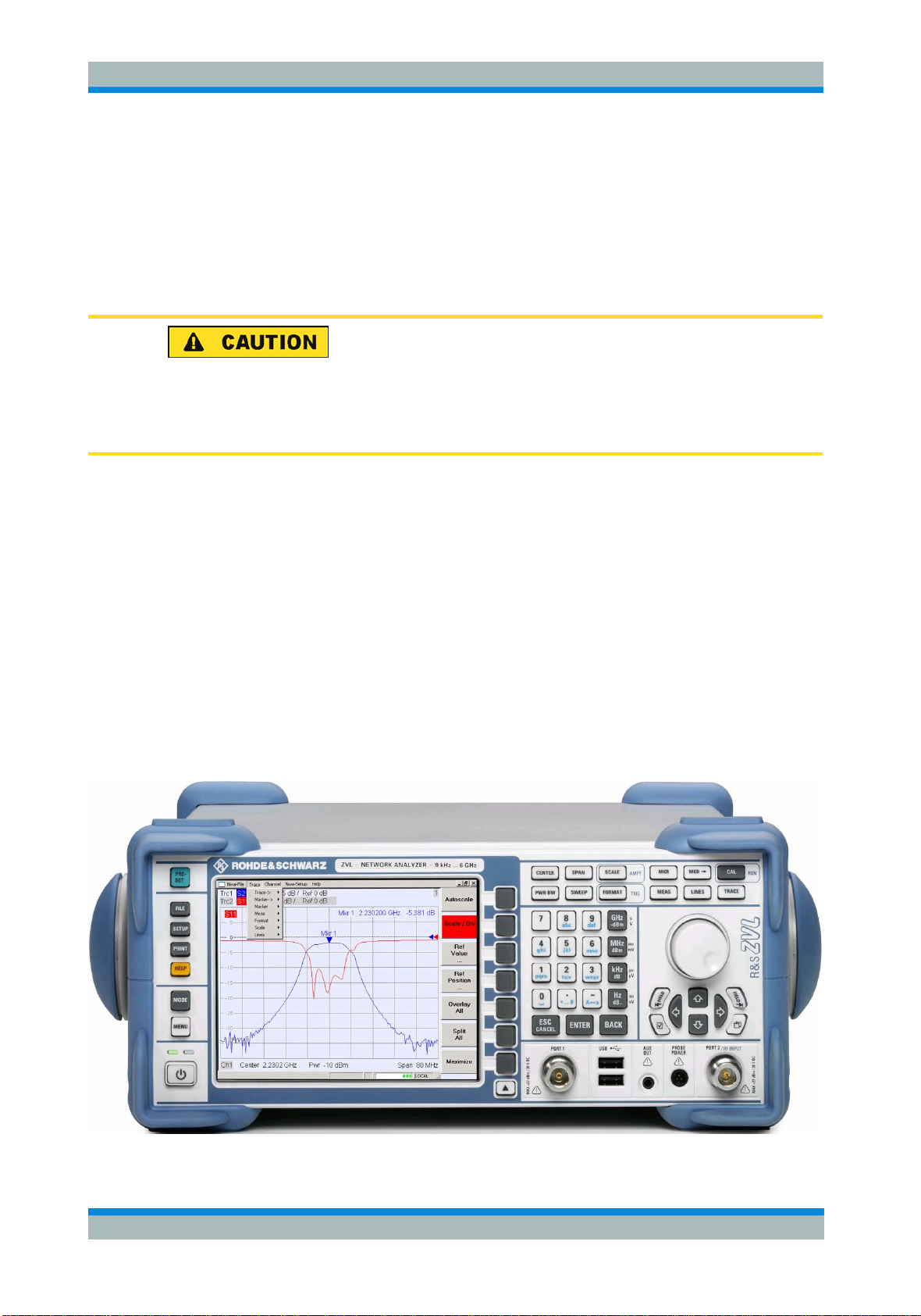
1.1 Front Panel Tour
The front panel of the network analyzer consists of the VGA display with the softkey
area, the hardkey areas, and the connectors area. Brief explanations on the controls
and connectors, the hardkey area and the rear panel can be found on the next pages.
Quick Start Guide 1303.6538.62 - 06
11
R&S ZVL Preparing for Use
Front Panel Tour
1.1.1 Display
The analyzer is equipped with a color display providing all control elements for the
measurements and the diagram areas for the results.
C Refer to section Navigation T ools of the Screen in Chapter 3 to learn how to use
menus, keys and softkeys.
C Refer to section Dis play El ements in Chapter 3 to obtain information about the
results in the diagram area.
C Refer to section Dis play Menu in the online help system and learn how to
customize the screen.
C Refer to the data sheet for the technical specifications of the display.
Screen saver
The screen saver function of the operating system switches off the display if the
analyzer receives no command for more than a specified period of time. It is switched
on again if any front panel key is pressed. To change the screen saver properties,
press SETUP – General Setup – More – Open Start Menu (or connect an external
keyboard and press CTRL + ESC) to open the start menu, and click Control Panel –
Display – Screen Saver.
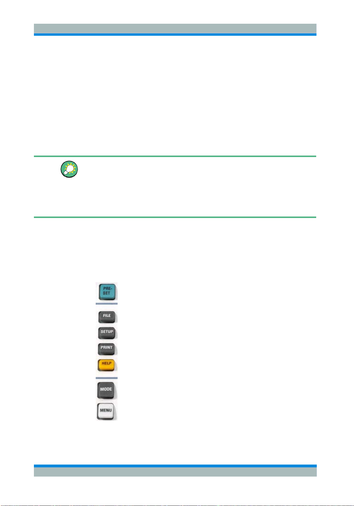
1.1.2 Setup Keys
The front panel keys to the left of the display provide utility functions, assistance, and
alternative measurement modes. Some of the keys are related to the spectrum
analyzer mode (with option R&S ZVL-K1), irrespective of the active mode.
C PRESET performs a general factory preset or user preset,
depending on the "Preset Scope" selected in the System
Configuration menu.
C FILE provides standard Windows™ functions to create, save,
and recall spectrum analyzer settings and results. For detailed
information refer to the spectrum analyzer help system (HELP).
Alternatively, use the functions in the Nwa-File menu of the
network analyzer mode.
C SETUP provides basic instrument configurations. For detailed
information refer to the spectrum analyzer help system (HELP).
Alternatively, use the functions in the Nwa-Setup menu of the
network analyzer mode, in particular the System Config. settings.
C PRINT customizes the printout, selects and configures the
printe
r. For detailed information refer to the spectrum analyzer
help system (HELP). Alternatively, use the functions in the NwaFile menu of the network analyzer mode
Quick Start Guide 1303.6538.62 - 06
C HELP calls the help system, depending on the active context.
The network analyzer and spectrum analyzer modes are
12
R&S ZVL Preparing for Use
Front Panel Tour
described in two separate help systems.
C MO
C MENU activates the highest softkey menu level of the current
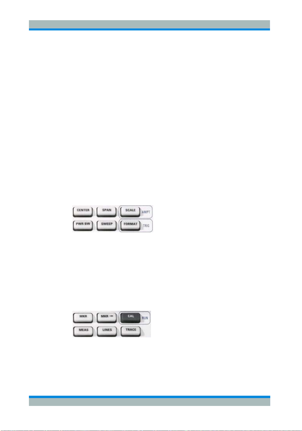
1.1.3 Function Keys
The keys in the upper right part of the front panel provide direct access to the most
important measurement settings. Each key opens a drop-down menu (softkey menu)
or activates a menu command (softkey) of the graphical user interface. The softkeys
are hidden after a while to make room for the display and the measurement results.
The links in the short descriptions below will take you to the detailed description for the
network analyzer mode. If the spectrum analyzer option (R&S ZVL-K1) is active, the
keys have a similar function. The network analyzer keys SCALE, FORMAT, and CAL
have no direct equivalent in spectrum analysis; they are replaced by the AMPT, TRIG,
and RUN keys, respectively.
DE ope
and spectrum analyzer modes.
spectrum analyzer context. For detailed information refer to the
spectrum analyzer help system (HELP). In network analyzer
mode, use the Function Keys or the menus across the top of the
main application window.
ns a dialog to switch between the network analyzer
C CENTER or SPAN define the center frequency and the width of the sweep range.
C SCALE defines how the current trace is presented in the diagram. If the spectrum
analyzer option (R&S ZVL-K1) is active, the key provides additional functions
affecting the displayed signal amplitude (AMPT).
C PWR BW defines the power of the internal signal source, sets the step attenuators
and the IF bandwidths.
C SWEEP defines the scope of measurement, including the sweep type, the number
of points, the measurement delay and the periodicity of the measurement.
C FORMAT defines how the measured data is presented in the graphical display. If
the spectrum analyzer option (R&S ZVL-K1) is active, the key provides trigger
settings (TRIG).
C MKR positions markers on a trace, configures their properties and selects the
format of the numerical readout.
C MARKER-> provides marker functions that allow you to search for values on
traces, define the sweep range, scale the diagram, and introduce an electrical
length offset.
Quick Start Guide 1303.6538.62 - 06
13
R&S ZVL Preparing for Use
become inactive or switches to the previous (next)
Front Panel Tour
C CAL provides all functions that are necessary to perform a system error correction
bration). If the spectrum analyzer option (R&S ZVL-K1) is active, the key starts
(cali
a new measurement (RUN).
C MEAS selects the quantity to be measured and displayed.
C LINES defines limits for measured values and activates the limit check.
C TRACE provides functions to handle traces in diagram areas, evaluate trace
statistics, and store trace data.
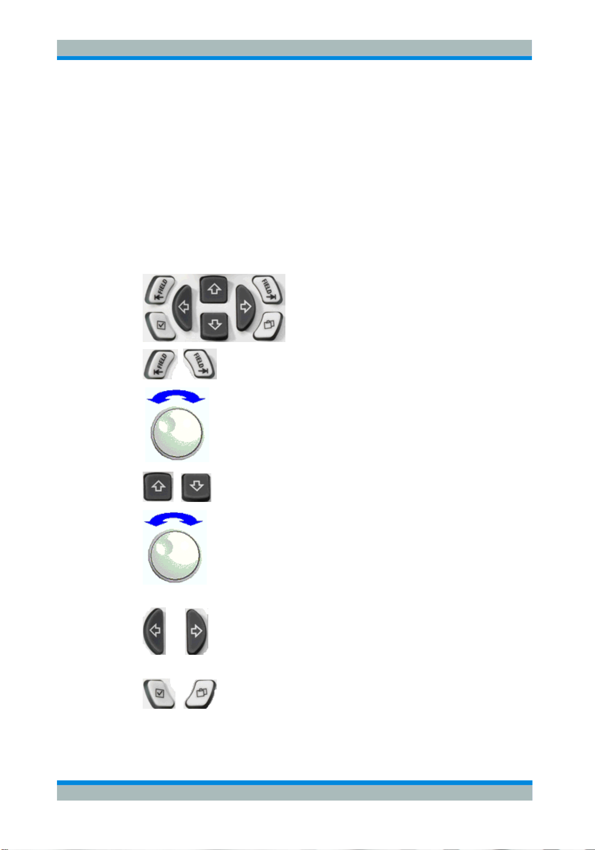
1.1.4 Navigation Keys
The navigation keys below the rotary knob are used to navigate within the analyzer
screen and the Help system, to access and control active elements.
The Left Field (= Tab) or Right Field (= Shift Tab) keys switch
between several active elements in dialogs and panes, e.g. in order
to access:
C All control elements (e.g. buttons, numerical or text input fields,
radio buttons, checkmarks, combo boxes etc.) in a dialog
C All links in a Help topic (not possible with the rotary knob)
The Cursor Up and Cursor Down keys are used to:
C Scroll up and down in lists, e.g. in pull-down lists, among menu
items, in a list of keywords, in the Help table of contents, or in
the Help topic text
C Increase and decrease numeric input values
Cursor Up (Down)
dialog element as soon as the beginning of the list is reached.
Cursor Up (Down) is equivalent to a rotation of the rotary knob to the
right (left).
The Cursor Left and Cursor Right keys are used to:
C Move the cursor to the left or right within input fields
C Compress or expand menus or the Help table of contents
Quick Start Guide 1303.6538.62 - 06
C Access the previous (next) menu in the menu bar
The Checkmark (= Space) key can be used to
C Insert a space character into character entry fields
C Switch a checkmark control in a dialog on or off
C Activate the selected active control element, e.g. a button in a
14
R&S ZVL Preparing for Use
or 1 and add the appropriate
Front Panel Tour
dialog or a link in the Help system
croll
C S
down in Help topic
The Next Tab key opens the next tab of a dialog, e.g. in the Help
navigation pane or in some of the spectrum analyzer dialogs.
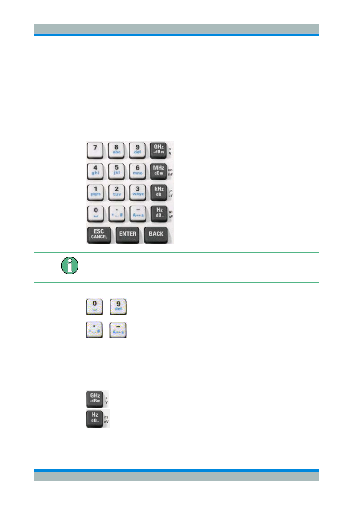
1.1.5 Data Entry Keys
The data entry keys are used to enter numbers and units.
Key activation
The data entry keys are only enabled while the cursor is placed on a data input field in
a dialog or in the Help navigation pane.
The keys 0 to 9 enter the corresponding numbers. In addition, these
...
keys can be used to insert characters in character input fields; see
section Data Entry in chapter 2.
The function of the . and – keys depends on the data type of the active
input field:
C In numeric input fields, the keys enter the decimal point and
change the sign of the entered numeric value. Multiple decimal
points are not allowed; pressing – for a second time cancels the
effect of the first entry.
C In character input fields, the keys enter a dot and a hyphen,
respectively. Both entries can be repeated as often as desired.
The function of the four unit keys depends on the data type of the
active input field; see Data Entry section in Chapter 3.
...
C In numeric input fields (e.g. in the numeric entry bar), the GHz / -
dBm, MHz / dBm, kHz / dB or Hz / dB.. keys multiply the entered
value with factors of 10
(-)9
, 10
(-)6
, 10
(-)3
physical unit.
Quick Start Guide 1303.6538.62 - 06
15
 Loading...