

Rohde&Schwarz R&S®ZVH Quick Start Guide Getting started

R&S®ZVH
Cable and Antenna Analyzer
Quick Start Guide
1309.6900.12 – 06

The Quick Start Guide describes the following R&S®ZVH models and options
● R&S ZVH4 (1309.6800.24)
● R&S ZVH8 (1309.6800.28)
● R&S ZVH-K1 (1309.6823.02)
● R&S ZVH-K9 (1309.6852.02)
● R&S ZVH-K39 (1309.6830.02)
The contents of this manual correspond to firmware version 1.90 and higher.
© 2021 Rohde & Schwarz GmbH & Co. KG
Muehldorfstr. 15, 81671 Munich. Germany
Phone: +49 89 4129-0
E-mail: info@rohde-schwarz.com
Internet: http://www.rohde-schwarz.com
81671 Munich, Germany
Subject to change – Data without tolerance limits is not binding.
R&S® is a registered trademark of Rohde & Schwarz GmbH & Co. KG.
Trade names are trademarks of the owners.
The following abbreviations are used throughout this manual:
R&S®ZVH is abbreviated as R&S ZVH.

R&S ZVH Table of Contents
Quick Start Guide 1309.6900.12 - 06 1
Table of Contents
Safety Instructions.............................................................................. 4
Instrucciones de seguridad ............................................................... 5
Sicherheitshinweise ........................................................................... 6
Consignes de sécurité ........................................................................ 7
Documentation Overview ................................................................... 8
Contacting Customer Support ......................................................... 10
1 Putting into Operation ...................................................................... 11
1.1 Unpacking the R&S ZVH ...........................................................................................12
1.2 Overview of Controls .................................................................................................13
1.3 Setting up the R&S ZVH ............................................................................................14
1.3.1 Using the AC Adapter ..................................................................................................15
1.3.2 Battery Operation .........................................................................................................16
1.3.3 Battery Maintenance ....................................................................................................18
1.3.3.1 Handling .......................................................................................................................18
1.3.3.2 Storage ........................................................................................................................18
1.3.3.3 Transportation ..............................................................................................................19
1.3.3.4 End of Life ....................................................................................................................19
1.4 Connectors on the R&S ZVH ....................................................................................20
1.4.1 RF Input .......................................................................................................................21
1.4.2 Tracking Generator Output ..........................................................................................22
1.4.3 Power Sensor Port .......................................................................................................22
1.4.4 Headphone Jack ..........................................................................................................23
1.4.5 AUX Input .....................................................................................................................23
1.4.6 BNC Connectors ..........................................................................................................24
1.4.6.1 EXT TRIG / EXT REF ..................................................................................................24
1.4.6.2 BIAS Port 1 / BIAS Port 2 ............................................................................................24
1.4.6.3 IF Output ......................................................................................................................25
1.4.7 Mini USB and LAN Ports .............................................................................................26
1.4.8 Mechanical Locking Device .........................................................................................26

R&S ZVH Table of Contents
Quick Start Guide 1309.6900.12 - 06 2
1.4.9 DC Port ........................................................................................................................27
1.4.10 USB Port ......................................................................................................................27
1.4.11 SD Card Slot ................................................................................................................27
1.5 Managing Options......................................................................................................28
1.5.1 Enabling Options..........................................................................................................28
1.5.2 Checking Installed Options ..........................................................................................28
1.5.3 Managing Options with the R&S License Manager .....................................................29
1.6 Configuring the R&S ZVH .........................................................................................31
1.6.1 Configuring the Hardware ............................................................................................32
1.6.2 Configuring Antennas ..................................................................................................34
1.6.3 Using the GPS Receiver ..............................................................................................35
1.6.4 Configuring Date and Time ..........................................................................................37
1.6.5 Selecting Regional Attributes .......................................................................................38
1.6.6 Configuring the Display ................................................................................................40
1.6.7 Configuring Audio Output ............................................................................................41
1.6.8 Configuring Power Supply ...........................................................................................42
1.6.9 Self Alignment ..............................................................................................................43
1.6.10 Using a PIN Code ........................................................................................................43
1.6.11 Resetting the R&S ZVH ...............................................................................................44
1.7 Connecting the R&S ZVH to a PC ............................................................................45
1.7.1 Connecting the R&S ZVH in a LAN .............................................................................45
1.7.2 Connecting the R&S ZVH in an existing LAN ..............................................................48
1.7.3 Connecting the R&S ZVH via USB ..............................................................................49
2 Getting Started .................................................................................. 50
2.1 Using the Measurement Wizard ...............................................................................51
2.1.1 Defining Measurement Sets ........................................................................................51
2.1.2 Uploading Measurement Sets .....................................................................................52
2.1.3 Performing Measurements ..........................................................................................53
2.1.4 Evaluating the Results .................................................................................................55
2.2 Identifying Cable Faults ............................................................................................56
2.3 Measuring Transmissions (Option R&S ZVH-K39) .................................................61
2.4 Using the Spectrum Analyzer (Option R&S ZVH-K1) .............................................63
2.4.1 Attenuating the Signal ..................................................................................................63

R&S ZVH Table of Contents
Quick Start Guide 1309.6900.12 - 06 3
2.4.2 Using the Preamplifier .................................................................................................65
2.4.3 Measuring CW Signals ................................................................................................66
2.5 Using a Power Sensor (Option R&S ZVH-K9) .........................................................68
2.5.1 Measuring the Power with a Power Sensor .................................................................69
2.5.2 Measuring Power and Return Loss .............................................................................71
2.6 Saving and Recalling Results and Settings ............................................................73
2.6.1 Saving Measurement Results ......................................................................................73
2.6.2 Recalling Measurement Results ..................................................................................74
Index .................................................................................................. 75

R&S ZVH Safety Instructions
Quick Start Guide 1309.6900.12 - 06 4
Safety Instructions
Risk of injury and instrument damage
The instrument must be used in an appropriate manner to prevent personal injury or
instrument damage.
● Do not open the instrument casing.
● Read and observe the "Basic Safety Instructions" delivered as printed brochure
with the instrument or in electronic format on the documentation CD-ROM.
● Read and observe the safety instructions in the following sections. Note that the
data sheet may specify additional operating conditions.
● Keep the "Basic Safety Instructions" and the product documentation in a safe place
and pass them on to the subsequent users.
The R&S ZVH has been designed for lab operation as well as for service and
maintenance applications in outdoor areas. Thus, the following safety instructions
apply in addition to or contrary to the “Basic Safety Instructions” leaflet.
1. The R&S ZVH is protected against dripping water and dust (IP degree 51) and can
thus be used in outdoor areas to a certain degree.
2. The R&S ZVH’s max. operating altitude is 4600 m above sea level and its max.
transport altitude is 12000 m above sea level.

R&S ZVH Instrucciones de seguridad
Quick Start Guide 1309.6900.12 - 06 5
Instrucciones de seguridad
Riesgo de lesiones y daños en el instrumento
El instrumento se debe usar de manera adecuada para prevenir descargas eléctricas,
incendios, lesiones o daños materiales.
● No abrir la carcasa del instrumento.
● Lea y cumpla las "Instrucciones de seguridad elementales" suministradas con el
instrumento como folleto impreso o en formato electrónico en el CD-ROM de
documentación.
● Lea y cumpla las instrucciones de seguridad incluidas en las siguientes secciones.
Se debe tener en cuenta que las especificaciones técnicas pueden contener
condiciones adicionales para su uso.
● Guarde bien las instrucciones de seguridad elementales, así como la
documentación del producto, y entréguelas a usuarios posteriores.
El R&S ZVH está diseñado tanto para el uso en el laboratorio como para aplicaciones
de servicio y mantenimiento al aire libre. En consecuencia, las instrucciones de
seguridad siguientes son aplicables de manera adicional a las “Informaciones
elementales de seguridad” (folleto) o en lugar de estas en los puntos en los que
diverjan.
1. El R&S ZVH está protegido contra las salpicaduras de agua y contra el polvo (IP
51), por lo que hasta cierto punto se puede usar en exteriores sin problemas.
2. La altitud máxima de funcionamiento del R&S ZVH es de 4600 m sobre el nivel del
mar, mientras que su altitud máxima de transporte es de 12 000 m sobre el nivel
del mar.

R&S ZVH Sicherheitshinweise
Quick Start Guide 1309.6900.12 - 06 6
Sicherheitshinweise
Gefahr von Verletzungen und Schäden am Gerät
Betreiben Sie das Gerät immer ordnungsgemäß, um elektrischen Schlag, Brand,
Verletzungen von Personen oder Geräteschäden zu verhindern.
● Öffnen Sie das Gerätegehäuse nicht.
● Lesen und beachten Sie die "Grundlegenden Sicherheitshinweise", die als
gedruckte Broschüre dem Gerät beiliegen oder elektronisch auf der
Dokumentation CD-ROM zu finden sind.
● Lesen und beachten Sie die Sicherheitshinweise in den folgenden Abschnitten;
möglicherweise enthält das Datenblatt weitere Hinweise zu speziellen
Betriebsbedingungen.
● Bewahren Sie die "Grundlegenden Sicherheitshinweise" und die
Produktdokumentation gut auf und geben Sie diese an weitere Benutzer des
Produkts weiter.
Der R&S ZVH wurde für den Einsatz im Labor sowie für Service- und
Wartungseinsätze im Freien entwickelt. Deshalb gelten zusätzlich oder im Gegensatz
zur Broschüre „Grundlegende Sicherheitshinweise‟ die folgenden Sicherheitshinweise.
1. Der R&S ZVH ist gegen Spritzwasser und Staub geschützt (IP-Schutzart 51) und
kann daher bis zu einem gewissen Grad im Freien verwendet werden.
2. Die maximale Betriebshöhe des R&S ZVH beträgt 4600 m ü. NN und die maximale
Transporthöhe 12000 m ü. NN

R&S ZVH Consignes de sécurité
Quick Start Guide 1309.6900.12 - 06 7
Consignes de sécurité
Risque de blessures et d'endommagement de l'appareil
L'appareil doit être utilisé conformément aux prescriptions afin d'éviter les
électrocutions, incendies, dommages corporels et matériels.
● N'ouvrez pas le boîtier de l'appareil.
● Lisez et respectez les "consignes de sécurité fondamentales" fournies avec
l’appareil sous forme de brochure imprimée ou disponibles en format électronique
sur le CD-ROM de documentation.
● Lisez et respectez les instructions de sécurité dans les sections suivantes. Il ne
faut pas oublier que la fiche technique peut indiquer des conditions d’exploitation
supplémentaires.
● Gardez les consignes de sécurité fondamentales et la documentation produit dans
un lieu sûr et transmettez ces documents aux autres utilisateurs.
Le R&S ZVH a été conçu pour le fonctionnement en laboratoire ainsi que pour les
applications de service et de maintenance en extérieur. Par conséquent, les
instructions de sécurité suivantes s’appliquent en plus de la fiche « Consignes
fondamentales de sécurité » ou s’opposent à elles.
1. Le R&S ZVH est protégé contre les projections d’eau et la poussière (niveau de
protection IP 51) et peut par conséquent être utilisé en extérieur dans une certaine
mesure.
2. Le R&S ZVH est utilisable jusqu’à une altitude maximale de 4600 m au-dessus du
niveau de la mer, et peut être transporté à une altitude maximale de 12000 m audessus du niveau de la mer.

R&S ZVH Documentation Overview
Quick Start Guide 1309.6900.12 - 06 8
Documentation Overview
The user documentation for the R&S ZVH is divided as follows:
Quick Start Guide
The Quick Start Guide provides basic information on the instrument's functions.
It covers the following topics:
● overview of all elements of the front and rear panels
● basic information on how to set up the R&S ZVH
● information on how to operate the R&S ZVH in a network
● instructions on how to perform measurements
Operating Manual
The Operating Manual provides a detailed description on the instrument's functions
It covers the following topics:
● instructions on how to set up and operate the R&S ZVH in its various operating
modes
● instructions on how to perform measurements with the R&S ZVH
● instructions on how to work with the available software options and applications
Manual for Remote Control Operation
The software manual for the R&S ZVH-K40 provides a detailed description of the
remote control option.
It covers the following topics:
● introduction to the operation of the R&S ZVH via remote control
● detailed description of the remote control commands available with the R&S ZVH-
K40 software application.
● description of the status reporting system
Service Manual
The Service Manual provides information on maintenance.
It covers the following topics:
● instructions on how to perform a performance test
● instructions on how to repair the R&S ZVH including a spare parts list
● mechanical drawings
Release Notes
The release notes describe the installation of the firmware, new and modified
functions, eliminated problems, and last minute changes to the documentation. The
corresponding firmware version is indicated on the title page of the release notes. The
current release notes are provided on the internet.

R&S ZVH Documentation Overview
Quick Start Guide 1309.6900.12 - 06 9
Internet Site
The internet site at: http://www.rohde-schwarz.com/product/zvh.html provides the most
up to date information on the R&S ZVH. The most recent manuals are available as
printable PDF files in the download area.
Also provided for download are firmware updates including the corresponding release
notes, instrument drivers, current data sheets, application notes and image versions.
Calibration certificates
The calibration certificates of your device are available online. Visit the R&S ZVH
product page and select the item to download the calibration certificate. You will be
forwarded to a Gloris page.
https://gloris.rohde-schwarz.com/calcert
Enter the device ID of your R&S ZVH and download the certificate. You can find the
device ID either in the "Setup" menu or on the label on the rear panel.

R&S ZVH Putting into Operation
Unpacking the R&S ZVH
Quick Start Guide 1309.6900.12 - 06 10
Contacting Customer Support
Technical support – where and when you need it
For quick, expert help with any Rohde & Schwarz product, contact our customer
support center. A team of highly qualified engineers provides support and works with
you to find a solution to your query on any aspect of the operation, programming or
applications of Rohde & Schwarz products.
Contact information
Contact our customer support center at www.rohde-schwarz.com/support, or follow this
QR code:

R&S ZVH Putting into Operation
Unpacking the R&S ZVH
Quick Start Guide 1309.6900.12 - 06 11
1 Putting into Operation
This chapter assists you in using the R&S ZVH for the first time.
It contains general information about the R&S ZVH as well as information about the
available connectors and the general system configuration.
Contents
● Unpacking the R&S ZVH (p. 12)
● Overview of Controls (p. 13)
● Setting up the R&S ZVH (p. 14)
● Connectors on the R&S ZVH (p. 20)
● Managing Options (p. 28)
● Configuring the R&S ZVH (p. 31)
● Connecting the R&S ZVH to a PC (p. 45)
R&S ZVH Putting into Operation
Unpacking the R&S ZVH
Quick Start Guide 1309.6900.12 - 06 12
1.1 Unpacking the R&S ZVH
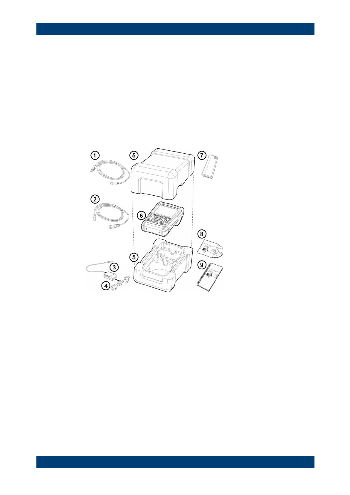
The R&S ZVH is delivered in formfitting packaging. It consists of an upper and a lower
shell. The two shells are held together by tape.
The packaging contains all accessories that are supplied with the instrument.
► Remove the tape and open the packaging.
► Remove the R&S ZVH and its accessories.
► Remove the protective film from the screen.
1 USB cable
2 LAN cable
3 AC adapter
4 AC plug (country specific)
5 Upper and lower shell
6 R&S ZVH
7 Lithium ion battery
8 CD-ROM
9 Quick Start manual

R&S ZVH Putting into Operation
Overview of Controls
Quick Start Guide 1309.6900.12 - 06 13
1.2 Overview of Controls
1 RF input (N-connector)
2 Headphone jack
3 BNC connectors (behind protective cap)
4 LAN and Mini USB ports (behind protective cap)
5 Softkey labels (on display)
6 Softkeys
7 Function keys
8 Alphanumeric keypad
9 Kensington lock
10 DC port
11 On/Off key
12 Entry keys
13 Unit keys
14 Cursor keys
15 Preset key
16 Rotary knob
17 Screenshot key
18 Setup key
19 Display
20 SD card slot / USB port (behind protective cap)
21 Tracking generator output (N-connector)
22 Power sensor jack
R&S ZVH Putting into Operation
Setting up the R&S ZVH
Quick Start Guide 1309.6900.12 - 06 14
1.3 Setting up the R&S ZVH
The R&S ZVH has been designed for lab operation as well as for service and
maintenance applications on-site.
Depending on the environment, you can adjust the viewing angle of the display and
either lay it out flat or prop it up using the support on the back of the R&S ZVH.
When laid out flat for operation from above, the R&S ZVH is still tilted slightly because
of the grip on its top. This position provides the optimum viewing angle for the display.
To allow easy operation from the front and still be able to read the display, you can
swing out the support on the back of the R&S ZVH.
For use on site or service measurements, it is best to hold the instrument in both
hands. All controls are easy to reach. It is also recommended to use the R&S HA-Z222
carrying bag in order to leave both hands free for work on the device under test (DUT).
You can also use the grip on the top of the R&S ZVH to hang it from cabinet doors, for
example.
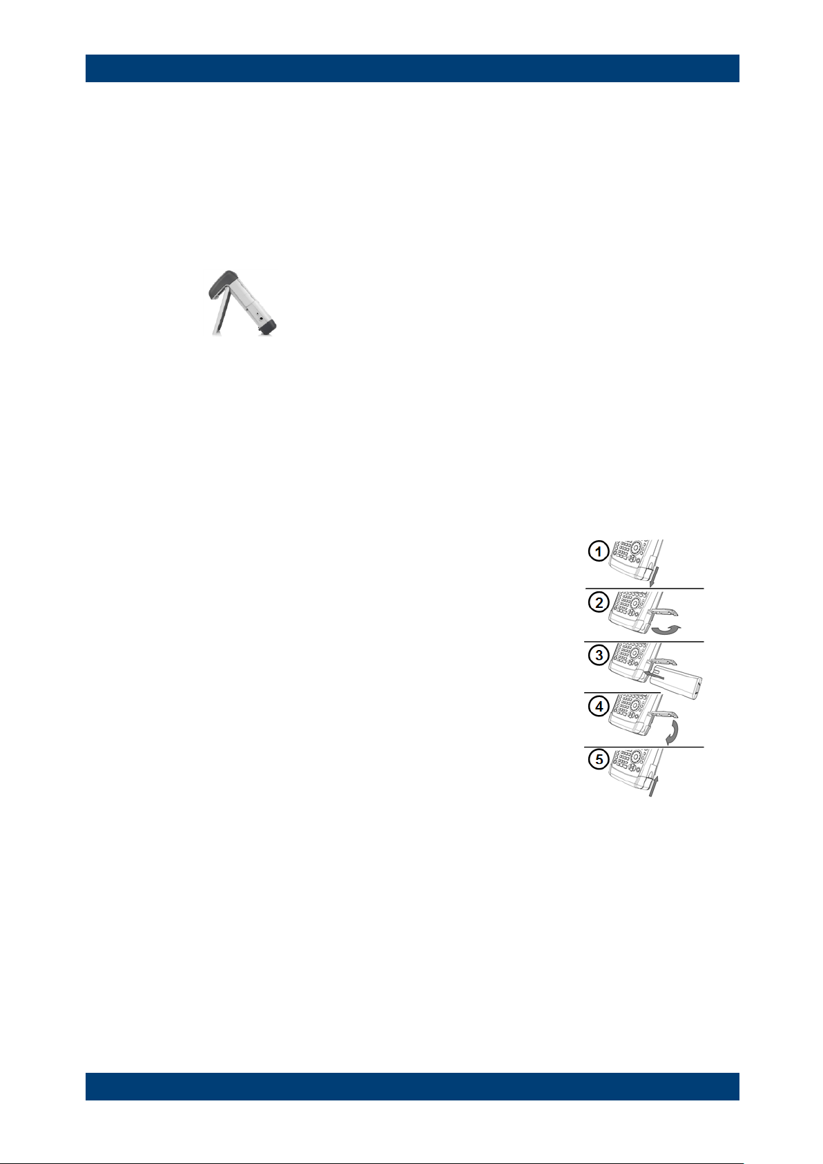
Before you turn on the R&S ZVH, you should insert the
lithium ion battery included in the delivery into the battery
compartment. The battery compartment is located on the
bottom right of the R&S ZVH.
(1) Press a finger against the recessed grip and push the
cover down.
(2) Open the cover.
(3) Insert the battery into the compartment with the round
side facing upwards and the handle facing outwards.
(4) Close the cover.
(5) Push the cover up until it clicks fully into place.
You can operate the R&S ZVH with the AC adapter or the battery. Both are included in
the delivery.

R&S ZVH Putting into Operation
Setting up the R&S ZVH
Quick Start Guide 1309.6900.12 - 06 15
1.3.1 Using the AC Adapter
Connect the AC adapter (R&S HA-Z201) to the DC port on the left side of the
R&S ZVH (1). Make sure to fully insert the plug into the port.
Depending on the system you need, firmly connect the appropriate plug included in the
delivery (2) to the AC adapter.
Finally, connect the plug to an AC power outlet.
The voltage range of the AC power supply is 100 V to 240 V AC.
When the R&S ZVH is supplied with power, you can turn it on with the button on the
front panel.
Risk of instrument damage
To avoid instrument damage,
● only use the power supply included in the delivery (R&S HA-Z201).
● make sure that AC supply voltage is compatible to the voltage specified on the
power supply unit.
● attach the appropriate adapter to the power supply.

R&S ZVH Putting into Operation
Setting up the R&S ZVH
Quick Start Guide 1309.6900.12 - 06 16
1.3.2 Battery Operation
The lithium ion battery has a capacity of approximately 4 Ah and allows operation of up
to three hours when it is fully charged.
The actual operation time depends on the current charge status, the ambient
temperature and the operating mode of the R&S ZVH.
The R&S ZVH shows the current charge status at the top of the display.
When fully charged, the battery icon is completely white. As the battery loses power,
the white color in the battery icon fades away until it turns red and starts to blink. When
the icon starts to blink, the battery low level has been reached. For more information
see "Configuring Power Supply" on page 42.
Note that the battery is not fully charged when it is dispatched. For battery operation
you have to charge it first.
To charge the battery, connect the AC power adapter included in the delivery. For
more information see "Using the AC Adapter" on page 15.
Charging time is about 2.5 hours when the R&S ZVH is switched off. If it is switched
on, the charging time is extended to about 3.5 hours, because the charging current is
reduced by the power drain of the R&S ZVH.
During operation in the field, you can also charge the battery with the R&S HA-Z202
car adapter (order no. 1309.6117.00). You can connect the car adapter to the DC port.
With the car adapter, you are able to charge the R&S ZVH via the car's cigarette lighter
socket.
While charging, the R&S ZVH displays an arrow within the battery charge status
indicator at the top right of the display to show that it is connected to the power supply
and is charging.
When the battery is fully charged (or when you use the R&S ZVH without a battery), a
plug icon is displayed instead of the battery icon.
You can set up the R&S ZVH to automatically turn off if no input is made after a
particular time period. The possible range is from 0 to 99 minutes. For more
information see "Configuring the Display" on page 40.
In the default state, the automatic cut-off is inactive.
A replacement battery (R&S FSH-Z206) with a capacity of approximately 6 Ah and an
operating time of 4.5 hours is available as an accessory. Charging time for the
replacement battery is about 3.5 hours if the R&S ZVH is switched off and about 4.5
hours if the R&S ZVH is switched on.

R&S ZVH Putting into Operation
Setting up the R&S ZVH
Quick Start Guide 1309.6900.12 - 06 17
Using an external battery charger
You can also use an external battery charger (R&S HA-Z203, order no. 1309.6123.00)
to charge an additional replacement battery.
To charge the battery externally, put the battery into the external charger and supply it
with power via the AC power adapter.
An orange LED (CHARGE) on the charger indicates the charging process. The orange
LED turns off when the battery is fully charged. When the battery is fully charged, a
green LED (READY) turns on instead.
1 External charger R&S HA-Z203
2 Lithium ion battery R&S HA-Z204 or HA-Z206
3 Power supply unit R&S Z201 or car adapter R&S HA-Z202
Turn off the R&S ZVH while driving or while the engine is on.
Operation of the R&S ZVH via the cigarette lighter socket while driving or while the
engine is on is prohibited.

R&S ZVH Putting into Operation
Setting up the R&S ZVH
Quick Start Guide 1309.6900.12 - 06 18
1.3.3 Battery Maintenance
The R&S ZVH comes with a lithium-ion battery. In general, these batteries are easy to
handle. When you handle the battery, mind the things mentioned in the safety
instructions and those in this chapter.
1.3.3.1 Handling
● The battery has been designed for a specific application. Do not use it for any
other application
● Do not connect batteries in series or parallel as it can cause serious damage.
● Observe correct polarities during installation and charging.
● Do not heat over 70°C. The battery contains thermal fuses that could activate and
render the battery inoperable.
● The battery contains an electronic device for protection against deep discharge,
overcharge and short-circuiting between the terminals.
- If you cannot discharge the battery, it may be deep discharged. Charge the
battery for 0.5 hours and check again.
- If you cannot charge the battery, it may be overcharged. Discharge the battery
and check again.
- If the battery has been short-circuited, charge it to reset the electronics.
- If the battery still does not work, contact the Rohde & Schwarz customer
support.
● Do not allow metallic objects to come into contact with the terminals.
● Do not solder directly to the battery.
1.3.3.2 Storage
The battery self-discharges while not in use. When storing the battery for an extended
period of time, make sure to
● handle the battery carefully to avoid short circuits. Make sure that leads and
terminals are insulated.
● keep the battery in the supplied packaging prior to use. The temperature must be
between -20°C and +50°C.
● store the battery at an initial state of charge between 15% and 50% of its capacity.
When calculating the initial state of charge, consider
- the maximum consumption of electronic devices
- the self-discharge of the battery - the higher the state of charge, the higher the
rate of self-discharge
● avoid a deep discharge of the battery. A deep discharge occurs when the state of
charge falls below 5% of the battery's capacity.
● recharge the battery at least every three months.
Should the battery voltage be low or even 0 V, the battery protection circuit may have
gone into a sleep mode. In that case, reset the battery with an approved charger.

R&S ZVH Putting into Operation
Setting up the R&S ZVH
Quick Start Guide 1309.6900.12 - 06 19
1.3.3.3 Transportation
No special regulations apply for transporting the battery. The battery cells contain no
metallic lithium.
1.3.3.4 End of Life
The capacity of the battery decreases after it has gone through numerous charge
cycles and nears its end of life. When the battery is dead, do not open the battery.
Dispose of .it at a suitable collection point.

R&S ZVH Putting into Operation
Connectors on the R&S ZVH
Quick Start Guide 1309.6900.12 - 06 20
1.4 Connectors on the R&S ZVH
The R&S ZVH has several connectors. The connectors are either on the upper, left or
right side.
Contents
● RF Input (p. 21)
● Tracking Generator Output (p. 22)
● Power Sensor Port (p. 22)
● Headphone Jack (p. 23)
● AUX Input (p. 23)
● BNC Connectors (p. 24)
● Mini USB and LAN Ports (p. 26)
● Mechanical Locking Device (p. 26)
● DC Port (p. 27)
● USB Port (p. 27)
● SD Card Slot (p. 27)

R&S ZVH Putting into Operation
Connectors on the R&S ZVH
Quick Start Guide 1309.6900.12 - 06 21
1.4.1 RF Input
The RF input is located on the top of the R&S ZVH.
Connect a cable or DUT to the RF input with an N connector. Use a cable to connect
the DUT to the R&S ZVH, if necessary.
Make sure not to overload the R&S ZVH when a DUT is connected.
The maximum power that is permissible at the RF input is 20 dBm (or 100 mW).
The R&S ZVH may be loaded with up to 30 dBm (or 1 W) for up to three minutes. If
you apply 1 W for a longer period, the R&S ZVH may be destroyed.
The RF input is protected from static discharges and voltage pulses by a limiting
circuit.
Risk of electrical shock
In order to avoid electrical shock, the DC input voltage must never exceed the value
specified on the housing.
Risk of instrument damage
To avoid damage to the coupling capacitor, input attenuator or the mixer, the DC input
voltage must never exceed the value specified in the data sheet.

R&S ZVH Putting into Operation
Connectors on the R&S ZVH
Quick Start Guide 1309.6900.12 - 06 22
1.4.2 Tracking Generator Output
The tracking generator output is located on the top of the R&S ZVH.
The tracking generator output power of the R&S ZVH is 0 dBm nominal.
With an integrated step attenuator, you can reduce the tracking generator output power
by a maximum of 40 dB in 1 dB steps.
Risk of instrument damage
To avoid damage to the tracking generator output, the reverse voltage up to the voltage
stated on the R&S ZVH housing must not be exceeded.
1.4.3 Power Sensor Port
The connector for power sensors is located on the top of the R&S ZVH.
The connector is configured especially for power sensors. It is used for both the power
supply and data transfer via the power sensor interface.
Additionally, you can connect accessories like the R&S TS-EMF isotropic antenna
(order no. 1158.9295.13) to the power sensor port.
 Loading...