

Rohde&Schwarz R&S®ZVH-K40 Remote Control Operation User Manual
R&S®ZVH
Remote Control via LAN or USB
Software Manual
1173.9005.12 – 11

The Software Manual describes the following R&S®ZVH models and options
● R&S ZVH-K40 (1309.7013.02)
for the R&S®ZVH models:
● R&S ZVH4 (1309.6800.24)
● R&S ZVH8 (1309.6800.28)
The contents of this manual correspond to firmware version 1.90 or higher.
© 2021 Rohde & Schwarz GmbH & Co. KG
Muehldorfstr. 15, 81671 Munich. Germany
Phone: +49 89 4129-0
E-mail: info@rohde-schwarz.com
Internet: http://www.rohde-schwarz.com
81671 Munich, Germany
Subject to change – Data without tolerance limits is not binding.
R&S® is a registered trademark of Rohde & Schwarz GmbH & Co. KG.
Trade names are trademarks of the owners.
Throughout this manual, products from Rohde & Schwarz are indicated without the ® symbol , e.g. R&S®ZVH is indicated as
R&S ZVH.

R&S ZVH Table of Contents
Software Manual 1173.9005.12 - 11 1
Table of Contents
Documentation Overview ................................................................... 6
Conventions Used in the Documentation ......................................... 7
1 Introduction ......................................................................................... 8
2 Interfaces and Protocols .................................................................... 9
2.1 LAN Interface ..............................................................................................................11
2.2 USB Interface .............................................................................................................11
2.3 Protocols ....................................................................................................................12
3 Setting Up the Remote Control Connection ................................... 14
3.1 Preparing for Remote Control ..................................................................................14
4 Instrument Model and Command Processing ................................ 15
4.1 Input Unit ....................................................................................................................15
4.2 Command Recognition .............................................................................................16
4.3 Data Base and Instrument Hardware .......................................................................16
4.4 Status Reporting System ..........................................................................................17
4.5 Output Unit .................................................................................................................17
5 SCPI Command Structure and Syntax ............................................ 18
5.1 Structure of a Command ...........................................................................................19
5.1.1 Common Commands ...................................................................................................19
5.1.2 Device-Specific Commands .........................................................................................20
5.1.2.1 Hierarchy ......................................................................................................................20
5.1.2.2 Multiple Keywords ........................................................................................................20
5.1.2.3 Optional Keywords .......................................................................................................21
5.1.2.4 Long and Short Form ...................................................................................................21
5.1.2.5 Parameter ....................................................................................................................22
5.1.2.6 Special Characters.......................................................................................................22
5.1.2.7 Numeric Suffix ..............................................................................................................23
5.1.3 Overview of Syntax Elements ......................................................................................24
5.2 Parameters .................................................................................................................25
5.2.1 Numeric Values ............................................................................................................25

R&S ZVH Table of Contents
Software Manual 1173.9005.12 - 11 2
5.2.2 Special Numeric Values ...............................................................................................26
5.2.3 Boolean Parameters ....................................................................................................26
5.2.4 Text ..............................................................................................................................27
5.2.5 Strings ..........................................................................................................................27
5.2.6 Block Data ....................................................................................................................27
5.3 Structure of a Program Message .............................................................................28
5.4 Responses to Queries ...............................................................................................29
6 Command Sequence and Command Synchronization .................. 30
7 Remote Control – Commands ......................................................... 31
7.1 Common Commands .................................................................................................32
7.2 Remote Commands of the Cable and Antenna Analyzer ......................................35
7.2.1 Configuring the Horizontal Axis ...................................................................................36
7.2.2 Configuring the Vertical Axis ........................................................................................41
7.2.3 Setting the Bandwidth ..................................................................................................47
7.2.4 Performing and Triggering Measurements ..................................................................48
7.2.4.1 Performing the Measurement ......................................................................................48
7.2.4.2 Triggering Measurements ............................................................................................48
7.2.5 Working with Traces ....................................................................................................50
7.2.6 Using Markers ..............................................................................................................55
7.2.7 Using Limit Lines..........................................................................................................64
7.2.8 Configuring and Using Measurement Functions .........................................................65
7.2.8.1 Selecting the Measurement Port .................................................................................65
7.2.8.2 Selecting the Cable Characteristics .............................................................................66
7.2.8.3 Selecting the Measurement Mode ...............................................................................66
7.2.8.4 Selecting the Measurement Format.............................................................................67
7.2.8.5 Reading Out Measurement Results.............................................................................68
7.2.8.6 Calibrating the Measurement .......................................................................................69
7.2.8.7 Working with a DTF List ...............................................................................................73
7.3 Remote Commands of the Spectrum Analyzer ......................................................75
7.3.1 Configuring the Horizontal Axis ...................................................................................76
7.3.2 Configuring the Vertical Axis ........................................................................................81
7.3.3 Setting the Bandwidths ................................................................................................87
7.3.4 Performing and Triggering Measurements ..................................................................89

R&S ZVH Table of Contents
Software Manual 1173.9005.12 - 11 3
7.3.4.1 Performing the Measurement ......................................................................................89
7.3.4.2 Capturing I/Q Data .......................................................................................................92
7.3.4.3 Triggering Measurements ............................................................................................94
7.3.5 Working with Traces ....................................................................................................97
7.3.6 Using Markers ............................................................................................................102
7.3.6.1 Markers and Delta Markers .......................................................................................102
7.3.6.2 Marker Functions .......................................................................................................102
7.3.7 Using Display Lines and Limit Lines ..........................................................................109
7.3.7.1 Display Lines ..............................................................................................................109
7.3.7.2 Limit Lines ..................................................................................................................110
7.3.8 Configuring and Using Measurement Functions .......................................................115
7.3.8.1 Working with Channel Tables ....................................................................................115
7.3.8.2 Power Measurements ................................................................................................118
7.3.8.3 Measuring the Channel Power ..................................................................................121
7.3.8.4 Measuring the Occupied Bandwidth ..........................................................................123
7.3.8.5 TDMA Measurements ................................................................................................124
7.3.8.6 Measuring the Adjacent Channel Leakage Ratio ......................................................125
7.3.8.7 Measuring the Harmonic Distortion ...........................................................................137
7.3.8.8 Measuring the AM Modulation Depth ........................................................................139
7.3.8.9 Measuring the Spectrum Emission Mask ..................................................................140
7.3.8.10 Measuring Spurious Emissions .................................................................................142
7.3.8.11 Using an Isotropic Antenna ........................................................................................143
7.4 Remote Commands of the Network Analyzer Mode ............................................145
7.4.1 Configuring the Horizontal Axis .................................................................................145
7.4.2 Configuring the Vertical Axis ......................................................................................146
7.4.3 Setting the Bandwidths ..............................................................................................151
7.4.4 Performing and Triggering the Measurement ............................................................151
7.4.5 Working with Traces ..................................................................................................152
7.4.6 Using Markers and Deltamarkers ..............................................................................154
7.4.6.1 Markers and Deltamarkers ........................................................................................154
7.4.6.2 Marker Functions .......................................................................................................156
7.4.7 Configuring the Measurement ...................................................................................158
7.4.7.1 Selecting the Measurement Port ...............................................................................158

R&S ZVH Table of Contents
Software Manual 1173.9005.12 - 11 4
7.4.7.2 Selecting the Measurement Mode .............................................................................158
7.4.7.3 Calibrating the Measurement .....................................................................................159
7.4.7.4 Selecting the Result Display ......................................................................................160
7.4.7.5 Selecting the Measurement Format...........................................................................161
7.4.7.6 Configuring the Vector Voltmeter (option R&S ZVH-K45) .........................................163
7.5 Remote Commands of the Power Meter ................................................................166
7.5.1 Using Power Sensors ................................................................................................166
7.5.1.1 Setting the Frequency ................................................................................................166
7.5.1.2 Configuring Power Level Readout .............................................................................167
7.5.1.3 Defining the Measurement Time ................................................................................169
7.5.1.4 Zeroing of the Power Sensor .....................................................................................169
7.5.1.5 Forward Power Display ..............................................................................................170
7.5.1.6 Defining the Video Bandwidth ....................................................................................170
7.5.1.7 Reading Out Measurement Results...........................................................................171
7.5.1.8 Selecting a Telecommunication Standard .................................................................172
7.6 File Management ......................................................................................................173
7.7 Making and Storing Screenshots ...........................................................................181
7.8 Configuring Data Capture .......................................................................................183
7.9 Saving Events ..........................................................................................................185
7.10 Configuring the Instrument ....................................................................................188
7.10.1 Mode Selection ..........................................................................................................188
7.10.2 Controlling the GPS Receiver ....................................................................................190
7.10.3 Display Configuration .................................................................................................195
7.10.4 Audio Settings ............................................................................................................197
7.10.5 Setting up a Network Connection ..............................................................................199
7.10.6 System Settings .........................................................................................................201
7.11 Status Reporting System ........................................................................................211
7.11.1 Structure of an SCPI Status Register ........................................................................211
7.11.1.1 CONDition part ...........................................................................................................211
7.11.1.2 PTRansition part ........................................................................................................212
7.11.1.3 NTRansition part ........................................................................................................212
7.11.1.4 EVENt part .................................................................................................................212
7.11.1.5 ENABle part ...............................................................................................................212

R&S ZVH Table of Contents
Software Manual 1173.9005.12 - 11 5
7.11.1.6 Sum bit .......................................................................................................................213
7.11.2 Overview of the Status Register ................................................................................213
7.11.3 Status Byte (STB) & Service Request Enable Register (SRE) .................................214
7.11.4 Event Status Register (ESR) and Event Status Enable Register (ESE) ...................215
7.11.4.1 STATus:OPERation Register ....................................................................................216
7.11.4.2 STATus:QUEStionable Register ................................................................................216
7.11.4.3 STATus:QUEStionable:FREQuency Register ...........................................................217
7.11.4.4 STATus:QUEStionable:LIMit Register .......................................................................217
7.11.4.5 STATus:QUEStionable:POWer Register ...................................................................217
7.11.5 Application of the Status Reporting Systems ............................................................218
7.11.5.1 Service Request .........................................................................................................218
7.11.5.2 Serial Poll ...................................................................................................................218
7.11.5.3 Query by Means of Commands .................................................................................219
7.11.5.4 Error Queue Query ....................................................................................................219
7.11.6 Reset Values of the Status Reporting System ..........................................................220
7.11.7 Remote Commands of the Status Reporting System ................................................221
Alphabetical List of Remote Commands ...................................... 226
Index ................................................................................................ 235

R&S ZVH Documentation Overview
Software Manual 1173.9005.12 - 11 6
Documentation Overview
The user documentation for the R&S ZVH is divided as follows:
Quick Start Guide
The Quick Start Guide provides basic information on the instrument's functions.
It covers the following topics:
● overview of all elements of the front and rear panels
● basic information on how to set up the R&S ZVH
● information on how to operate the R&S ZVH in a network
● instructions on how to perform measurements
Operating Manual
The Operating Manual provides a detailed description on the instrument's functions
It covers the following topics:
● instructions on how to set up and operate the R&S ZVH in its various operating
modes
● instructions on how to perform measurements with the R&S ZVH
● instructions on how to work with the available software options and applications
Service Manual
The Service Manual provides information on maintenance.
It covers the following topics:
● instructions on how to perform a performance test
● instructions on how to repair the R&S ZVH including a spare parts list
● mechanical drawings
Release Notes
The release notes describe the installation of the firmware, new and modified
functions, eliminated problems, and last minute changes to the documentation. The
corresponding firmware version is indicated on the title page of the release notes. The
current release notes are provided on the internet.
Internet Site
The internet site at: http://www.rohde-schwarz.com/product/zvh.html provides the most
up to date information on the R&S ZVH. The most recent manuals are available as
printable PDF files in the download area.
Also provided for download are firmware updates including the corresponding release
notes, instrument drivers, current data sheets, application notes and image versions.

R&S ZVH Conventions Used in the Documentation
Software Manual 1173.9005.12 - 11 7
Conventions Used in the Documentation
The following conventions are used throughout the R&S R&S ZVH Software Manual:
Typographical conventions
Convention
Description
“Graphical user interface elements”
All names of graphical user interface elements both on the screen
and on the front and rear panels, such as dialog boxes, softkeys,
menus, options, buttons etc., are enclosed by quotation marks.
“KEYS”
Key names are written in capital letters and enclosed by quotation
marks.
Input
Input to be entered by the user is displayed in italics.
File names, commands,
program code
File names, commands, coding samples and screen output are
distinguished by their font.
"Links"
Links that you can click are displayed in blue font.
"References"
References to other parts of the documentation are enclosed by
quotation marks.
Other conventions
● Remote commands: Remote commands may include abbreviations to simplify
input. In the description of such commands, all parts that have to be entered are
written in capital letters. Additional text in lower-case characters is for information
only.

R&S ZVH Introduction
LAN Interface
Software Manual 1173.9005.12 - 11 8
1 Introduction
With the software application R&S ZVH-K40 installed on the instrument, it is possible
to operate your R&S ZVH via remote control. In this manual you will find all information
necessary to remotely control the R&S ZVH.
Enabling the Option
The Remote Control Option R&S ZVH-K40 is enabled by entering a key code. The key
code is based on the unique serial number of the instrument. To retrofit an option,
enable it with a key code.
► Press the SETUP key.
► Press the "Installed Options" softkey
► Select "Install Option..." under the "Option Administration" header.
► Confirm with ENTER.
An entry box in the lower right corner of the screen is displayed.
► Type in the the appropriate option key.
► Confirm with ENTER.
If the correct key code is entered, the R&S ZVH displays
If an invalid key code is entered, the R&S ZVH displays

R&S ZVH Interfaces and Protocols
LAN Interface
Software Manual 1173.9005.12 - 11 9
2 Interfaces and Protocols
The R&S ZVH supports two different interfaces for remote control.
● LAN Interface: The protocol is based on TCP/IP and supports the VXI-11 standard.
● USB Interface
The connectors are located at the side of the instrument and permit a connection to a
controller for remote control via a local area network (LAN) or directly via USB.
SCPI
SCPI (Standard Commands for Programmable Instruments) commands - messages are used for remote control. Commands that are not taken from the SCPI standard
follow the SCPI syntax rules. The instrument supports the SCPI version 1999. The
SCPI standard is based on standard IEEE 488.2 and aims at the standardization of
device-specific commands, error handling and the status registers. The tutorial
"Automatic Measurement Control - A tutorial on SCPI and IEEE 488.2" from John M.
Pieper (R&S order number 0002.3536.00) offers detailed information on concepts and
definitions of SCPI.
The requirements that the SCPI standard places on command syntax, error handling
and configuration of the status registers are explained in detail in the following
sections. Tables provide a fast overview of the bit assignment in the status registers.
The tables are supplemented by a comprehensive description of the status registers.
VISA
VISA is a standardized software interface library providing input and output functions to
communicate with instruments. The I/O channel (LAN or USB) is selected at
initialization time by means of a channel-specific resource string. For more information
about VISA refer to its user documentation.
The programming examples for remote control are all written in Microsoft® VISUAL
BASIC®. Access to the VISA functions require the declaration of the functions and
constants prior to their use in the project. This can be accomplished either by adding
the modules VISA32.BAS and VPPTYPE.BAS or a reference to the VISA32.DLL to the
project.

R&S ZVH Interfaces and Protocols
LAN Interface
Software Manual 1173.9005.12 - 11 10
The modules visa32.bas and vpptype.bas can be found in the following location:
<VXIpnpPath>\WinNT\include (typically C:\VXIpnp\WinNt\include).
Resetting the R&S ZVH
Manual operation is designed for maximum possible operating convenience. In
contrast, the priority of remote control is the "predictability" of the device status.
Therefore, control programs should always define an initial device status (e.g. with the
command *RST) and then implement the required settings.

R&S ZVH Interfaces and Protocols
LAN Interface
Software Manual 1173.9005.12 - 11 11
2.1 LAN Interface
To be integrated in a LAN, the instrument is equipped with a standard LAN interface,
consisting of a connector, a network interface and protocols (VXI-11).
Instrument access via VXI-11 is usually achieved from high level programming
platforms by using VISA as an intermediate abstraction layer. VISA encapsulates the
low level VXI-11 (LAN) or USB function calls and thus makes the transport interface
transparent for the user. The necessary VISA library is available as a separate product.
For details contact your local R&S sales representative.
2.2 USB Interface
For remote control via the USB connection, the PC and the instrument must be
connected via the USB interface. The required driver comes with the
R&S InstrumentView software package and is automatically installed on the PC with
the software package.
The driver adresses the instrument via the USB interface with the fix IP address
172.16.10.10.
In addition, a remote control connection via the SCPI interface requires the VISA
library to be installed on the PC.
R&S ZVH Interfaces and Protocols
Protocols
Software Manual 1173.9005.12 - 11 12
2.3 Protocols
VXI-11 Basics
The VXI-11 standard is based on the ONC-RPC protocol which in turn relies on TCP/IP
as the network/transport layer. The TCP/IP network protocol and the associated
network services are preconfigured. TCP/IP ensures connection-oriented
communication, where the order of the exchanged messages is adhered to and
interrupted links are identified. With this protocol, messages cannot be lost.
Remote control of an instrument via a network is based on standardized protocols
which follow the OSI reference model (see Fig. below).
Application SCPI
Presentation
Session
Transport
Network
Data Link
Physical
XDR (VXI-11)
ONC-RPC
TCP / UDP
IP
Ethernet/802.3
802.3/10BASE-T
Figure 2-1: Example for LAN remote control based on the OSI reference model
Based on TCP/UDP, messages between the controller and the instrument are
exchanged via open network computing (ONC) - remote procedure calls (RPC). With
XDR (VXI-11), legal RPC messages are known as VXI-11 standard. Based on this
standard, messages are exchanged between the controller and the instrument. The
messages are identical with SCPI commands. They can be organized in four groups:
● program messages (control command to the instrument)
● response messages (values returned by the instrument)
● service request (spontaneous queries of the instrument)
● low-level control messages (interface messages).
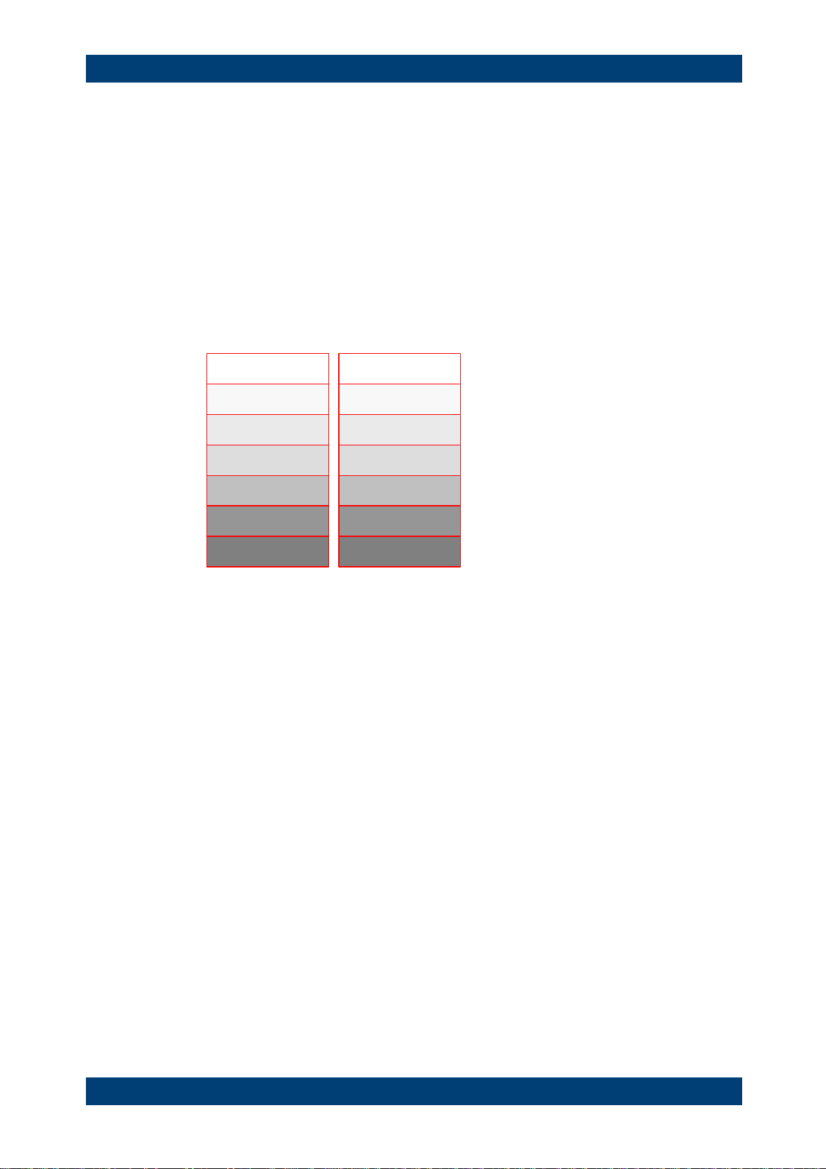
A VXI-11 link between a controller and an instrument uses three channels: core, abort
and interrupt channel. Instrument control is mainly performed on the core channel
(program, response and low-level control messages). The abort channel is used for
immediate abort of the core channel; the interrupt channel transmits spontaneous
service requests of the instrument. Link setup itself is very complex. For more details
refer to the VXI-11 specification.
R&S ZVH Interfaces and Protocols
Protocols
Software Manual 1173.9005.12 - 11 13
Instrument
Core channel
(program, response,
control messages)
Abort channel (abort)
Interrupt channel
(service request)
Controller
Figure 2-2: VXI-11 channels between instrument and controller
The number of controllers that can address an instrument is practically unlimited in the
network. In the instrument, the individual controllers are clearly distinguished. This
distinction continues up to the application level in the controller, i.e. two applications on
a computer are identified by the instrument as two different controllers.
Controller
Controller
Controller
Instrument
Figure 2-3: Remote control via LAN from several controllers
The controllers can lock and unlock the instrument for exclusive access. This regulates
access to the instrument of several controllers.

R&S ZVH Setting Up the Remote Control Connection
Preparing for Remote Control
Software Manual 1173.9005.12 - 11 14
3 Setting Up the Remote Control Connection
3.1 Preparing for Remote Control
The short and simple operating sequence below shows how to put the instrument into
operation and quickly set its basic functions. The current IP address for LAN operation
is shown in the SETUP – Instrument Setup Menu. In case of USB connection the IP
address is fixed to 172.16.10.10.
Refer to the Quick Start Guide for instructions on how to change the IP address.
► Connect the instrument to the LAN or directly to the controller via USB.
► Switch on the instruments.
► Write and start the following program on the controller:
status = viOpenDefaultRM(defaultRM)
'open default resource manager
status = viOpen(DefaultRM, "TCPIP::172.16.10.10", 0, 0, vi)
'in case of USB connection
status = viopen(DefaultRM, "TCPIP::xxx.xxx.xxx.xxx", 0, 0, vi)
'in case of a LAN connection, with xxx.xxx.xxx.xxx = IP address
cmd = "*RST;*CLS"
status = viWrite(vi, Cmd, Len(Cmd), retCount)
'reset instrument and clear status registers
cmd = "FREQ:CENT 100MHz"
status = viWrite(vi, Cmd, Len(Cmd), retCount)
'set center frequency to 100 MHz
cmd = "FREQ:SPAN 10MHz"
status = viWrite(vi, Cmd, Len(Cmd), retCount)
'set span to 10 MHz
cmd = "DISP:TRAC:Y:RLEV -10dBm"
status = viWrite(vi, Cmd, Len(Cmd), retCount)
'set reference level to -10 dBm
viclose vi
viclose default RM
The instrument now performs a sweep in the frequency range of 95 MHz to 105 MHz.
Changing the IP Address
In order to operate the instrument via remote control, it must be accessed via LAN (IP
address) or USB (fixed IP address). If the factory-set remote control address does not
fit in the network environment, it can be changed. Refer to the Quick Start Guide,
chapter "Setting up a LAN or USB Connection to a PC", for instructions on how to
change the IP address.
R&S ZVH Instrument Model and Command Processing
Input Unit
Software Manual 1173.9005.12 - 11 15
4 Instrument Model and Command
Processing
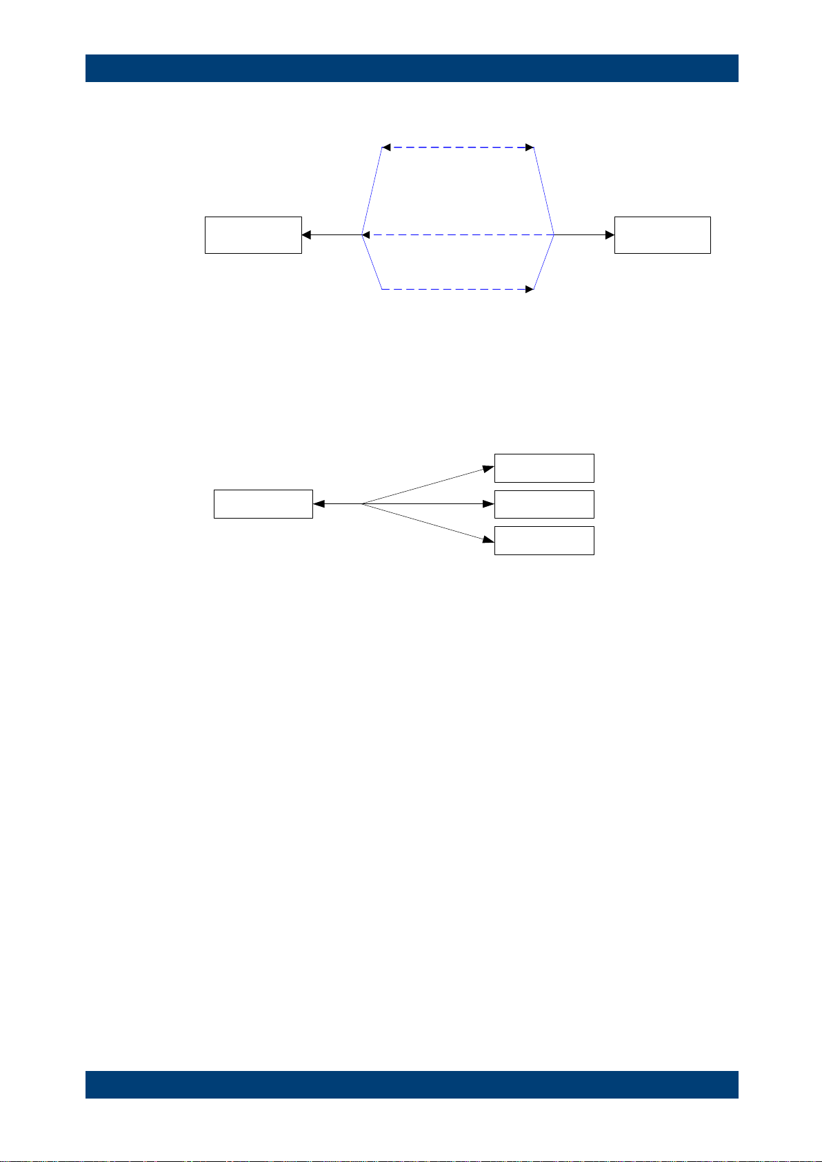
The block diagram in Fig. 1-2 shows how SCPI commands are serviced in the
instrument. The individual components work independently and simultaneously. They
communicate with each other by means of so-called "messages".
Input unit with
input buffer
Command
recognition
Instrument
hardware
Instrument
settings database
Output unit with
output buffer
Status reporting
system
USB interface
Ethernet
USB interface
Ethernet
Figure 4-1: Instrument model in the case of remote control
4.1 Input Unit
The input unit receives commands character by character from the controller and
collects them in the input buffer. The input unit sends a message to the command
recognition as soon as the input buffer is full or as soon as it receives a delimiter,
<PROGRAM MESSAGE TERMINATOR>, as defined in IEEE 488.2, or the interface
message DCL.
If the input buffer is full, the traffic is stopped and the data received up to then are
processed. Subsequently the traffic is continued. If, however, the buffer is not yet full
when receiving the delimiter, the input unit can already receive the next command
during command recognition and execution. The receipt of DCL clears the input buffer
and immediately resets the command recognition.

R&S ZVH Instrument Model and Command Processing
Command Recognition
Software Manual 1173.9005.12 - 11 16
4.2 Command Recognition
The command recognition analyses the data received from the input unit. It proceeds
in the order in which it receives the data. Only DCL is serviced with priority, for
example GET (Group Execute Trigger) is only executed after the commands received
before. Each recognized command is immediately transferred to the internal instrument
settings data base but not executed immediately.
The command recognition detects syntax errors in the commands and transfers them
to the status reporting system. The rest of a program message after a syntax error is
analyzed further if possible and serviced. After the syntax test, the value range of the
parameter is checked, if required.
If the command recognition detects a delimiter, it passes the command to an execution
unit that performs the instrument settings. In the meantime, the command recognition
is ready to process new commands (overlapping execution). A DCL command is
processed in the same way.
4.3 Data Base and Instrument Hardware
Here the expression "instrument hardware" denotes the part of the instrument fulfilling
the actual instrument function - signal generation, measurement etc. The controller is
not included. The term "data base" denotes a database that manages all the
parameters and associated settings required for setting the instrument hardware.
Setting commands lead to an alteration in the data set. The data set management
enters the new values (e.g. frequency) into the data set, however, only passes them on
to the hardware when requested by the command recognition. This only takes place at
the end of a program message.
The data are checked for compatibility with the current instrument settings before they
are transmitted to the instrument hardware. If the execution is not possible, an
"execution error" is signaled to the status reporting system. The corresponding settings
are discarded.
Before passing on the data to the hardware, the settling bit in the STATus:OPERation
register is set (refer to section "STATus:OPERation Register"). The hardware executes
the settings and resets the bit again as soon as the new state has settled. This fact can
be used to synchronize command servicing.
Queries induce the data set management to send the desired data to the output unit.

R&S ZVH Instrument Model and Command Processing
Status Reporting System
Software Manual 1173.9005.12 - 11 17
4.4 Status Reporting System
For detailed information refer to section "Status Reporting System".
4.5 Output Unit
The output unit collects the information requested by the controller, which it receives
from the data base management. It processes it according to the SCPI rules and
makes it available in the output buffer.
If the instrument is addressed as a talker without the output buffer containing data or
awaiting data from the data base management, the output unit sends error message
"Query UNTERMINATED" to the status reporting system. No data are sent to the
controller, the controller waits until it has reached its time limit. This behavior is defined
by IEEE 488.2 and SCPI.

R&S ZVH SCPI Command Structure and Syntax
Output Unit
Software Manual 1173.9005.12 - 11 18
5 SCPI Command Structure and Syntax
SCPI (Standard Commands for Programmable Instruments) describes a standard
command set for programming instruments, irrespective of the type of instrument or
manufacturer. The goal of the SCPI consortium is to standardize the device-specific
commands to a large extent. For this purpose, a model was developed which defines
the same functions inside a device or for different devices. Command systems were
generated which are assigned to these functions. Thus it is possible to address the
same functions with identical commands. The command systems are of a hierarchical
structure.
SCPI is based on standard IEEE 488.2, i.e. it uses the same syntactic basic elements
as well as the common commands defined in this standard. Part of the syntax of the
device responses is defined with greater restrictions than in standard IEEE 488.2 (see
section "Responses to Queries").
Remote command examples
Not all commands used in the following examples are implemented in the instrument.

R&S ZVH SCPI Command Structure and Syntax
Structure of a Command
Software Manual 1173.9005.12 - 11 19
5.1 Structure of a Command
The commands consist of a so-called header and, in most cases, one or more
parameters. Header and parameter are separated by a "white space" (ASCII code 0 to
9, 11 to 32 decimal, e.g. blank). The headers may consist of several key words.
Queries are formed by directly appending a question mark to the header.
5.1.1 Common Commands
Common commands consist of a header preceded by an asterisk "*" and one or
several parameters, if any.
Examples
*RST
RESET, resets the device
*ESE 253
EVENT STATUS ENABLE, sets the bits of the event status enable
register
*ESR?
EVENT STATUS QUERY, queries the contents of the event status
register.
R&S ZVH SCPI Command Structure and Syntax
Structure of a Command
Software Manual 1173.9005.12 - 11 20
5.1.2 Device-Specific Commands
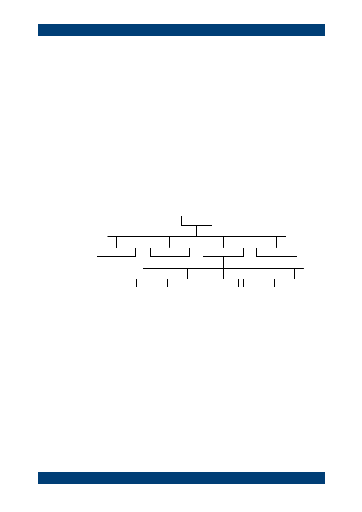
5.1.2.1 Hierarchy
Device-specific commands are of hierarchical structure. The different levels are
represented by combined headers. Headers of the highest level (root level) have only
one key word. This key word denotes a complete command system.
Example
SENSe
This key word denotes the SENSe command system.
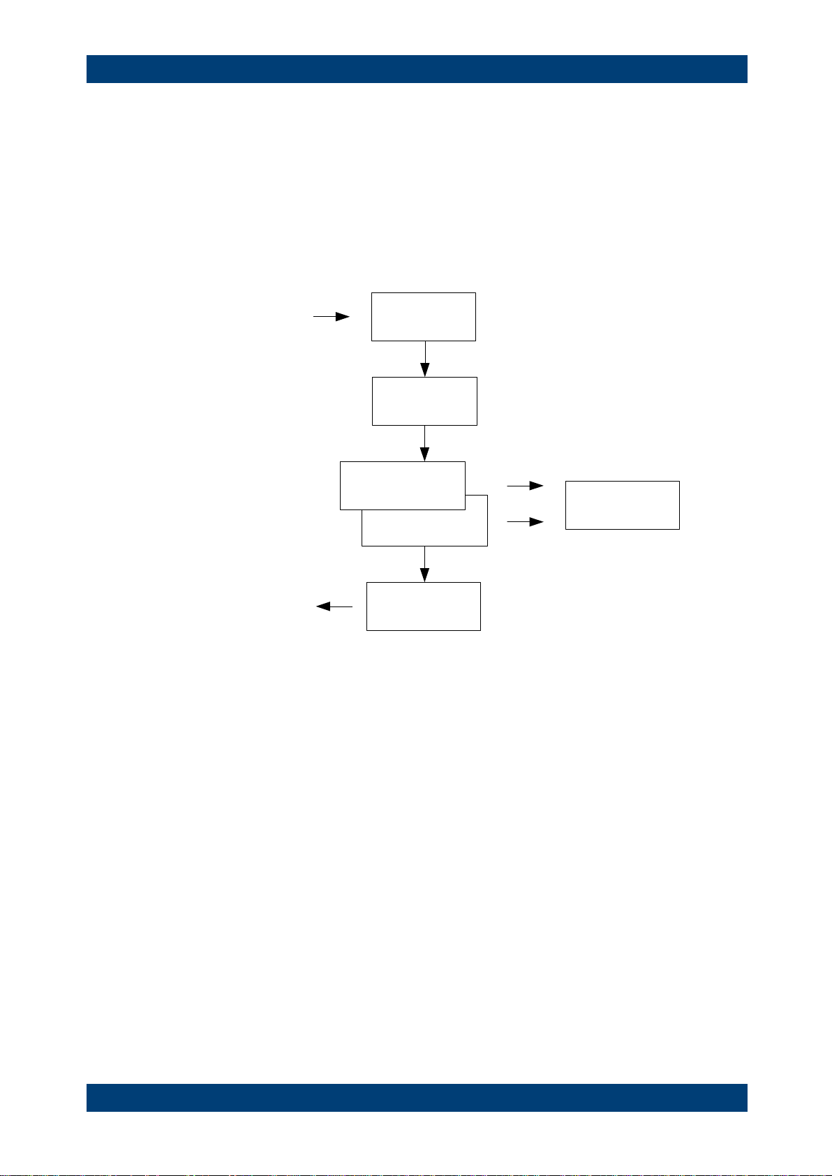
For commands of lower levels, the complete path has to be specified, starting on the
left with the highest level, the individual key words being separated by a colon ":".
Example
SENSe:FREQuency:SPAN 10MHZ
This command lies in the third level of the SENSe system. It sets the frequency span.
SENSe
BANDwidth
FUNCtion
FREQuency DETector
STARt STOP CENTer SPAN OFFSet
Figure 5-1: Tree structure the SCPI command systems using the SENSe system as example
5.1.2.2 Multiple Keywords
Some key words occur in several levels within one command system. Their effect
depends on the structure of the command, i.e. at which position in the header of a
command they are inserted.
Examples
SOURce:FM:POLarity NORMal
This command contains key word POLarity in the third command level. It defines the
polarity between modulator and modulation signal.
SOURce:FM:EXTernal:POLarity NORMal
This command contains key word POLarity in the fourth command level. It defines the
polarity between modulation voltage and the resulting direction of the modulation only
for the external signal source indicated.

R&S ZVH SCPI Command Structure and Syntax
Structure of a Command
Software Manual 1173.9005.12 - 11 21
5.1.2.3 Optional Keywords
Some command systems permit certain key words to be inserted into the header or
omitted. These key words are marked by square brackets in the description. The full
command length must be recognized by the instrument for reasons of compatibility
with the SCPI standard. Some commands are considerably shortened by these
optional key words.
Example
[SENSe]:BANDwidth[:RESolution]:AUTO
This command couples the resolution bandwidth of the instrument to other parameters.
The following command has the same effect:
BANDwidth:AUTO
Optional keywords with numeric suffixes
Do not omit an optional keyword if it includes a numeric suffix that is relevant for the
effect of the command.
Example
DISPlay[:WINDow<1...4>]:MAXimize <Boolean>
Command DISP:MAX ON refers to window 1.
In order to refer to a window other than 1, you must include the optional WINDow
parameter with the suffix for the required window.
DISP:WIND2:MAX ON refers to window 2.
5.1.2.4 Long and Short Form
The key words feature a long form and a short form. Either the short form or the long
form can be entered, other abbreviations are not permitted.
Example
STATus:QUEStionable:ENABle 1
is equivalent to
STAT:QUES:ENAB 1
Upper and lower case notation of commands
Upper-case and lower-case notation only serves to distinguish the two forms in the
manual, the instrument itself does not distinguish upper-case and lower-case letters.

R&S ZVH SCPI Command Structure and Syntax
Structure of a Command
Software Manual 1173.9005.12 - 11 22
5.1.2.5 Parameter
The parameter must be separated from the header by a "white space". If several
parameters are specified in a command, they are separated by a comma ",". A few
queries permit the parameters MINimum, MAXimum and DEFault to be entered. Refer
to "Parameters" for a detailed description of the various parameters.
Example
SENSe:FREQuency:STOP? MAXimum
Response: 3.5E9
This query requests the maximal value for the stop frequency.
5.1.2.6 Special Characters
|
A vertical stroke in parameter definitions indicates alternative possibilities in the
sense of "or". The effect of the command differs, depending on which parameter
is used.
Example
DISPlay:FORMat SINGle | SPLit
If parameter SINGle is selected, full screen is displayed, in the case of SPLit,
split screen is displayed.
A selection of key words with an identical effect exists for several commands.
These keywords are indicated in the same line; they are separated by a vertical
stroke. Only one of these keywords needs to be included in the header of the
command. The effect of the command is independent of which of the keywords is
used.
Example
SENSe:BANDwidth|BWIDth[:RESolution]
The two following commands with identical meaning can be created. They set the
frequency of the fixed frequency signal to 1 kHz:
SENSe:BAND 1
SENSe:BWID 1
[ ]
Key words in square brackets can be omitted when composing the header. The
full command length must be accepted by the instrument for reasons of
compatibility with the SCPI standards.
Example
[SENSe:]BANDwidth|BWIDth[:RESolution]
SENS:BAND:RES
is equivalent to
BAND
Parameters in square brackets can be incorporated optionally in the command or
omitted as well.

R&S ZVH SCPI Command Structure and Syntax
Structure of a Command
Software Manual 1173.9005.12 - 11 23
Example
MMEMory:NETWork:MAP
<string>,<string>[,string>,<string>,<boolean>]
Entries in square brackets are optional or can be omitted.
{ }
Parameters in curly brackets are optional and can be inserted once or several
times, or omitted.
Example
SENSe:LIST:FREQuency <numeric_value>{,<numeric_value>}
The following are valid commands:
SENS:LIST:FREQ 10
SENS:LIST:FREQ 10,20
SENS:LIST:FREQ 10,20,30,40
5.1.2.7 Numeric Suffix
If a device features several functions or features of the same kind, e.g. inputs, the
desired function can be selected by a suffix added to the command. Entries without
suffix are interpreted like entries with the suffix 1. Optional keywords must be specified
if they select a function with the suffix.
Example
SYSTem:COMMunicate:SERial2:BAUD 9600
This command sets the baud rate of a second serial interface.
Suffix counting
In case of remote control, suffix counting may differ from the numbers of the
corresponding selection used in manual operation. SCPI prescribes that suffix counting
starts with 1. Suffix 1 is the default state and used when no specific suffix is specified.
Some standards define a fixed numbering, starting with 0. With GSM, for instance,
slots are counted from 0 to 7. In the case of remote control, the slots are selected with
the suffixes 1 to 8. If the numbering differs in manual operation and remote control, it is
indicated with the respective command.

R&S ZVH SCPI Command Structure and Syntax
Structure of a Command
Software Manual 1173.9005.12 - 11 24
5.1.3 Overview of Syntax Elements
The following table offers an overview of the syntax elements.
:
The colon separates the key words of a command. In a program message the
separating semicolon marks the uppermost command level.
;
The semicolon separates two commands within a program message. It does not
alter the path.
,
The comma separates several parameters of a command.
?
The question mark forms a query.
*
The asterisk marks a common command.
"
Quotation marks introduce a string and terminate it.
#
The hash symbol # introduces binary, octal, hexadecimal and block data.
● Binary: #B10110
● Octal: #O7612
● Hexa: #HF3A7
● Block: #21312
A "white space" (ASCII-Code 0 to 9, 11 to 32 decimal, e.g. blank) separates
header and parameter.

R&S ZVH SCPI Command Structure and Syntax
Parameters
Software Manual 1173.9005.12 - 11 25
5.2 Parameters
For most commands a parameter needs to be supplemented. The parameter has to be
separated from the header by a "white space". Possible parameters are:
● Numeric values
● Special numeric values
● Boolean parameters
● Text
● Character strings
● Block data.
The type of parameter required for each command and the allowed range of values are
specified in the command description.
5.2.1 Numeric Values
Numeric values can be entered in any form, i.e. with sign, decimal point and exponent.
Values exceeding the resolution of the instrument are rounded up or down. The
mantissa may comprise up to 255 characters, the exponent must lie inside the value
range -32000 to 32000. The exponent is introduced by an "E" or "e". Entry of the
exponent alone is not permissible. In the case of physical quantities, the unit can be
entered. Permissible unit prefixes are G (giga), MA (mega), MOHM and MHZ are also
possible), K (kilo), M (milli), U (micro) and N (nano). If the unit is missing, the basic unit
is used.
Example
SENSe:FREQuency:STOP 1.5GHz = SENSe:FREQuency:STOP 1.5E9

R&S ZVH SCPI Command Structure and Syntax
Parameters
Software Manual 1173.9005.12 - 11 26
5.2.2 Special Numeric Values
The texts MINimum, MAXimum, DEFault, UP and DOWN are interpreted as special
numeric values. In case of a query, the numeric value is returned.
● MIN/MAX
MINimum and MAXimum denote the minimum and maximum value.
● DEF
DEFault denotes a preset value which has been stored in the EPROM. This value
conforms to the default setting, as it is called by the *RST command
● UP/DOWN
UP, DOWN increases or reduces the numerical value by one step. The step width
can be specified via an allocated step command for each parameter which can be
set via UP, DOWN.
● INF/NINF
INFinity, Negative INFinity (NINF) Negative INFinity (NINF) represent the
numerical values -9.9E37 or 9.9E37, respectively. INF and NINF are only sent as
device reponses.
● NAN
Not A Number (NAN) represents the value 9.91E37. NAN is only sent as device
response. This value is not defined. Possible causes are the division of zero by
zero, the subtraction of infinite from infinite and the representation of missing
values.
Example:
Setting command: SENSe:FREQuency:STOP MAXimum
Query: SENSe:FREQuency:STOP?, Response: 3.5E9
5.2.3 Boolean Parameters
Boolean parameters represent two states. The ON state (logically true) is represented
by ON or a numerical value unequal to 0. The OFF state (logically untrue) is
represented by OFF or the numerical value 0. The numerical values are provided as
response for query.
Example
Setting command: CALCulate:MARKer:STATe ON
Query: CALCulate:MARKer:STATe?, Response: 1

R&S ZVH SCPI Command Structure and Syntax
Parameters
Software Manual 1173.9005.12 - 11 27
5.2.4 Text
Text parameters observe the syntactic rules for key words, i.e. they can be entered
using a short or long form. Like any parameter, they have to be separated from the
header by a white space. In the case of a query, the short form of the text is provided.
Example
Setting command: INPut:COUPling GROund
Query: INPut:COUPling?, Response: GRO
5.2.5 Strings
Strings must always be entered in quotation marks (' or ").
Example
SYSTem:LANGuage "SCPI" or SYSTem:LANGuage 'SCPI'
5.2.6 Block Data
Block data are a transmission format which is suitable for the transmission of large
amounts of data. A command using a block data parameter has the following structure:
Example
HEADer:HEADer #45168xxxxxxxx
ASCII character # introduces the data block. The next number indicates how many of
the following digits describe the length of the data block. In the example the 4 following
digits indicate the length to be 5168 bytes. The data bytes follow. During the
transmission of these data bytes all end or other control signs are ignored until all
bytes are transmitted.

R&S ZVH SCPI Command Structure and Syntax
Structure of a Program Message
Software Manual 1173.9005.12 - 11 28
5.3 Structure of a Program Message
A program message may consist of one or several commands. It is terminated by the
program message terminator which is the NL (New Line) charcter for LAN and USB
connections.
Several commands in a program message must be separated by a semicolon ";". If the
next command belongs to a different command system, the semicolon is followed by a
colon. A colon ":" at the beginning of a command marks the root node of the command
tree.
Example:
CALL InstrWrite(analyzer, "SENSe:FREQuency:CENTer
100MHz;:INPut:ATTenuation 10")
This program message contains two commands. The first one is part of the SENSe
command system and is used to determine the center frequency of the instrument. The
second one is part of the INPut command system and sets the input signal attenuation.
If the successive commands belong to the same system, having one or several levels
in common, the program message can be abbreviated. For that purpose, the second
command after the semicolon starts with the level that lies below the common levels
(see also Fig. 1-1). The colon following the semicolon must be omitted in this case.
Example:
CALL InstrWrite(analyzer, "SENSe:FREQuency:STARt
1E6;:SENSe:FREQuency:STOP 1E9")
This program message is represented in its full length and contains two commands
separated from each other by the semicolon. Both commands are part of the SENSe
command system, subsystem FREQuency, i.e. they have two common levels.
When abbreviating the program message, the second command begins with the level
below SENSe:FREQuency. The colon after the semicolon is omitted. The abbreviated
form of the program message reads as follows:
CALL InstrWrite(analyzer, "SENSe:FREQuency:STARt 1E6;STOP 1E9")
However, a new program message always begins with the complete path.
Example:
CALL InstrWrite(analyzer, "SENSe:FREQuency:STARt 1E6")
CALL InstrWrite(analyzer, "SENSe:FREQuency:STOP 1E9")
 Loading...