

Rohde&Schwarz R&S®ZVA110 Getting Started Getting started
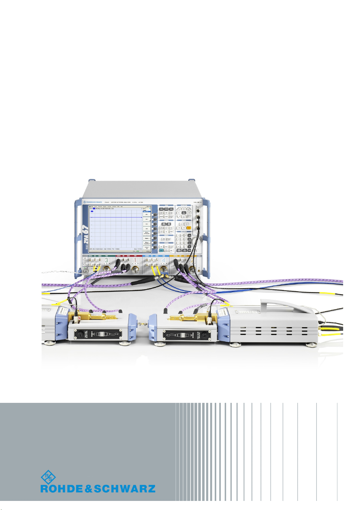
R&S®ZVA110
Broadband Measurements Using the
1 mm External Test Sets
Getting Started
(=>]2Ì)
1314450262
Version 03
Getting Started

This Getting Started guide describes the following network analyzer types:
●
R&S® ZVA110 complete system based on R&S®ZVA67
– regular power, stock number 1312.7004.03
– regular power, without RF cables, stock number 1312.7004.05
– high power, stock number 1312.7004.13
– high power, without RF cables, stock number 1312.7004.15
●
R&S® ZVA110 modular system
– regular power, stock number 1312.7004.04
– high power, stock number 1312.7004.14
It complements the Getting Started guide for all R&S®ZVA network analyzers, stock number 1145.1090.62
and the Getting Started guide for frequency converters with electronic attenuators R&S®ZVA-ZxxxE, stock
number 1307.7197.62. It describes the operation of the R&S®ZVA110 with external test sets.
© 2018 Rohde & Schwarz GmbH & Co. KG
Mühldorfstr. 15, 81671 München, Germany
Phone: +49 89 41 29 - 0
Fax: +49 89 41 29 12 164
Email: info@rohde-schwarz.com
Internet: www.rohde-schwarz.com
Subject to change – Data without tolerance limits is not binding.
R&S® is a registered trademark of Rohde & Schwarz GmbH & Co. KG.
Trade names are trademarks of the owners.
1314.4502.62 | Version 03 | R&S®ZVA110
Throughout this document, R&S® is abbreviated as R&S.
1
Safety Instructions
Risk of injury and instrument damage
The instrument must be used in an appropriate manner to prevent
electric shock, fire,
●
●
●
●
Keep the "Basic Safety Instructions" and the product documentation
Riesgo de lesiones y daños en el instrumento
El instrumento se debe usar de manera adecuada para p
descargas eléctricas, incendios, lesiones o daños materiales.
●
●
●
especificaciones técnicas pueden contener condiciones adicionales
●
Instrucciones de seguridad
Sicherheitshinweise
Consignes de sécurité
personal injury or instrument damage.
Do not open the instrument casing.
Read and observe the "Basic Sa fety Instructions" delivered as
printed brochure with the instrument.
Read and observe the safety instructions in the following sections.
Note that the data sheet may specify additional operating conditions.
in a safe place and pass them on to the subsequent users.
No abrir la carcasa del instrumento.
Lea y cumpla las "Instrucciones de seguridad elementales"
suministradas con el instrumento como folleto impreso.
Lea y cumpla las instrucciones de seguridad incluidas en las
siguientes secciones. Se debe tener en cuenta que las
para su uso.
Guarde bien las instrucciones de seguridad elementales, así como
la documentación del producto, y entréguelas a usuarios
posteriores.
revenir
1171.1307.42 - 05
2
Gefahr von Verletzungen und Schäden am Gerät
Betreiben Sie das Gerät immer ordnungsgemäß, um elektrischen
Schlag, Brand, Verletzungen von Personen oder Geräteschäden zu
verhindern.
●
●
●
●
Risque de blessures et d'endommagement de l'appareil
L'ap
les électrocutions, incendies, dommages corporels et matériels.
●
●
●
suivantes. Il ne faut pas oublier que la fiche technique peut indiquer
●
Öffnen Sie das Gerätegehäuse nicht.
Lesen und beachten Sie die "Grundlegenden Sicherheitshinweise",
die als gedruckte Broschüre dem Gerät beiliegen.
Lesen und beachten Sie die Sicherheitshinweise in den folgenden
Abschnitten; möglicherweise enthält das Datenblatt weitere
Hinweise zu speziellen Betriebsbedingungen.
Bewahren Sie die "Grundlegenden Sicher h ei t s hinweise" und die
Produktdokumentation gut auf und geben Sie diese an weitere
Benutzer des Produkts weiter.
pareil doit être utilisé conformément aux prescriptions afin d'éviter
N'ouvrez pas le boîtier de l'appareil.
Lisez et respectez les "consignes de sécurité fondamentales"
fournies avec l’app ar eil sous forme de brochure imprimée.
Lisez et respectez les instructions de sécurité dans les sections
des conditions d’exploitation supplémentaires.
Gardez les consignes de sécurité fondamentales et la
documentation produit dans un lieu sûr et transmettez ces
documents aux autres utilisateurs.
1171.1307.42 - 05

R&S®ZVA110
2.2.1 Test Port Connectors ......................................................................................................8
2.3.1 Test Port........................................................................................................................ 10
2.3.2 H/L SWITCH Connector................................................................................................10
2.3.3 Rear Panel.................................................................................................................... 10
2.3.4 Fuse Holder...................................................................................................................12
Contents
Contents
1 Safety Instructions.................................................................................5
2 Preparing the Analyzer for Use.............................................................7
2.1 Operation with External Test Sets...............................................................................7
2.2 R&S ZVA110 Network Analyzer Connectors...............................................................8
2.3 Diplexer Connectors..................................................................................................... 9
2.4 Frequency Converter Connectors............................................................................. 12
2.4.1 Waveguide Flange........................................................................................................ 12
2.4.2 Rear Panel.................................................................................................................... 12
2.4.2.1 Standby Switch............................................................................................................. 13
2.4.2.2 Power Supply Connector.............................................................................................. 13
2.4.2.3 Fuse Holder...................................................................................................................14
2.4.2.4 RF Connectors – Input.................................................................................................. 14
2.4.2.5 IF Connectors – Output.................................................................................................15
2.4.2.6 Power Control Connector..............................................................................................15
2.5 Putting the Analyzer into Operation.......................................................................... 15
2.5.1 Unpacking and Checking the Instrument...................................................................... 15
2.5.2 Positioning the Instrument.............................................................................................16
2.5.3 Adjusting the Feet of the Test Set................................................................................. 16
2.5.4 Connecting the Control Cable....................................................................................... 17
2.5.5 Connecting the Power Control Cable............................................................................17
2.5.6 Connecting RF Cables.................................................................................................. 17
2.5.7 Connecting the Converter to the DC Supply................................................................. 21
2.5.8 Switching On the External Test Set...............................................................................21
2.5.9 Mounting a DUT............................................................................................................ 22
2.5.10 Replacing Fuses........................................................................................................... 22
2.6 Maintenance................................................................................................................ 22
3Getting Started 1314.4502.62 ─ 03

R&S®ZVA110
3.10 Additional Information................................................................................................30
Contents
2.7 Storing and Packing................................................................................................... 22
3 Basic Operation....................................................................................24
3.1 Required Equipment................................................................................................... 24
3.2 Measurement Principle...............................................................................................24
3.3 Activating the ZVA110-BU Measurement Mode........................................................24
3.4 Entering Power Coefficients...................................................................................... 25
3.5 Connecting the External Test Sets............................................................................26
3.6 Power and Frequency Settings..................................................................................27
3.7 Calibration................................................................................................................... 28
3.8 Measurement............................................................................................................... 28
3.9 Troubleshooting..........................................................................................................29
4 Dismounting Frequency Converters.................................................. 31
4.1 Service Re-Calibration................................................................................................32
Index......................................................................................................33
4Getting Started 1314.4502.62 ─ 03

R&S®ZVA110
Safety Instructions
1 Safety Instructions
The vector network analyzer R&S ZVA110 has been designed and tested in accordance with the EC Certificate of Conformity. It has left the manufacturer’s plant in a condition fully complying with safety standards.
Risk of instrument damage
To prevent instrument damage, make sure to read through and observe the following
safety instructions.
ESD protective measures
Protect the vector network analyzer and the external test sets against damage due to
electrostatic discharge (ESD). Use the wrist strap and grounding cord supplied with the
analyzer and connect yourself to the GND connector at the front panel of the analyzer.
For details, refer to the R&S ZVA Getting Started guide, stock no. 1145.1090.62.
Input powers RF IN and LO IN
The RF input power at the connectors RF IN and LO IN must not exceed the maximum
values quoted in the data sheet. The maximum values are below the maximum RF
source power of the network analyzer. The "ZVA110-BU" mode ensures compatible
source powers.
Before you connect your external test set to the network analyzer, always activate the
"ZVA110-BU" mode using the "Frequency Converter" dialog (see Chapter 3.3, "Activat-
ing the ZVA110-BU Measurement Mode", on page 24).
Avoid heavy shocks
Heavy shocks can damage inner parts of the devices. Shockproof packing must be
used for storing or dispatching the analyzer and the external test sets.
Opening the instrument
Do not open the frequency converter and diplexer elements of the external test sets. It
can only be repaired at the manufacturer's servicing department.
Using frequency converters separately
The frequency converters can be dismounted from the external test sets and used separately (see Chapter 4, "Dismounting Frequency Converters", on page 31). The
waveguide flanges of the dismounted converters and of the test port adapters must be
protected against mechanical damage. Furthermore, the waveguides must be shielded
from dust.
Protect the waveguide flange of the dismounted converter by leaving a test port
adapter connected. When the converter is not in use, attach one of the included pro-
5Getting Started 1314.4502.62 ─ 03

R&S®ZVA110
Safety Instructions
tective caps to the adapter. Avoid scratching the contact surfaces of the waveguide
flanges.
6Getting Started 1314.4502.62 ─ 03
R&S®ZVA110
Preparing the Analyzer for Use
Operation with External Test Sets
2 Preparing the Analyzer for Use
The R&S ZVA110 vector network analyzer supports two different measurement modes:
●
Measurements with internal test sets cover a frequency range between 10 MHz
and approx. 67 GHz.
The R&S ZVA110 is based on a four-port R&S ZVA67 vector network analyzer. The
DUT can be connected to any of the four test ports of the R&S ZVA67. One- to
four-port measurements are supported as described in the R&S ZVA Getting Started guide, stock number 1145.1090.62, and in the network analyzer's help system.
●
Measurements with external test sets cover an extended frequency range between
10 MHz and 110 GHz. The DUT is connected to the 1 mm connectors at the front
of the diplexers R&S ZVA-ZD110. This measurement mode is described in the
present manual.
This chapter describes the external test sets and their connection to the DUT and to
the R&S ZVA110 vector network analyzer. A typical measurement example is presented in Chapter 3, "Basic Operation", on page 24.
The measurement mode is selected in the "Frequency Converter" tab of the "System
Configuration" dialog: "<NONE>" for measurements with internal test sets, "ZVA110BU" for external test sets. See Chapter 3.3, "Activating the ZVA110-BU Measurement
Mode", on page 24.
2.1 Operation with External Test Sets
The external test sets enable a frequency range between 10 MHz and 110 GHz. The
analyzer combines two different measurement methods to achieve this extended
range.
●
At frequencies below approx. 67 GHz (i.e. in "low frequency" mode), the frequency
converter in the external test set is bypassed. The source signals of analyzer ports
PORT 1 / 2 are directly fed to the 1 mm test port connectors of the diplexers. The
network analyzer measures the a-waves and b-waves from the REF OUT and
MEAS OUT on the diplexers, respectively. Analyzer ports PORT 3 / 4 and the RF
connectors LO IN, RF IN, REF OUT, and MEAS OUT on the rear panel of the converters are not used.
●
To achieve frequencies above approx. 67 GHz (i.e. to measure in "high frequency"
mode), the frequency converter in the external test set is used. The source signals
of analyzer ports PORT 1 / 2 are fed to the frequency converters, the converted
signals are routed to the 1 mm test port connectors of the diplexers. The frequency
converters use frequency multipliers to transform the source signal into a high-frequency stimulus signal. An additional Local Oscillator (LO) signal from PORT 4 of
the analyzer is used for down-conversion of the reference and measurement channels. A power divider feeds the LO signal to both the left and the right converter.
This test setup ensures a stable phase relationship between both LO signals.
7Getting Started 1314.4502.62 ─ 03
R&S®ZVA110
2.2 R&S ZVA110 Network Analyzer Connectors
Preparing the Analyzer for Use
ZVA110 Network Analyzer Connectors
R&S
The analyzer measures the a-waves from REF OUT and the b-waves from MEAS
OUT on the converters. The RF connectors REF OUT, MEAS OUT on the rear
panel of the diplexers are not used.
The network analyzer automatically switches between low frequency and high frequency mode, depending on the stimulus frequency; see Chapter 2.3.2, "H/L SWITCH
Connector", on page 10. There is no need to change the test setup and cabling.
The R&S ZVA110 is based on a four-port R&S ZVA67 vector network analyzer.
The front and rear panel controls and the connectors of the analyzer are described in
the R&S ZVA Getting Started guide, stock number 1145.1090.62 and in the analyzer's
help system. The following sections describe special aspects for measurements with
external test sets.
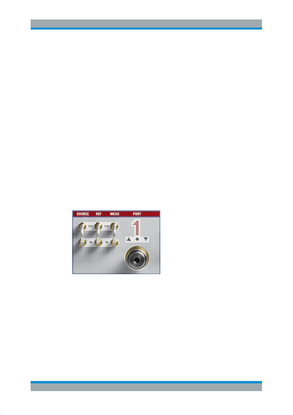
2.2.1 Test Port Connectors
The R&S ZVA67 of the R&S ZVA110 is equipped with four complete test port connector
groups. The PORT 1 to PORT 4 connector groups are similar. Each of them consists of
a bidirectional, ruggedized 1.85 mm connector and 3 pairs of 1.85 mm (V) connectors
for direct generator and receiver access.
The connectors are used alternatively:
●
The ruggedized 1.85 mm connector serves as a test port connector for one- to
four-port measurements with internal test set. In this operating mode, the three
1.85 mm connector pairs are not needed. However, they can provide an extended
measurement functionality (see R&S ZVA Getting Started guide, stock number
1145.1090.62, and the network analyzer's help system). Unused OUT/IN loops
must be jumpered as shown in the figure above.
●
The SOURCE OUT connector provides the RF source signal for the external test
set. SOURCE OUT is connected to the rear panel of the diplexer. In the low frequency range below approx. 67 GHz, REF IN and MEAS IN receive the reference
waves and measured waves from the diplexer, respectively. The 1 mm connector
of the diplexer serves as a test port connector; the ruggedized 1.85 mm connectors
at PORT 1 / 2 are not needed.
8Getting Started 1314.4502.62 ─ 03

R&S®ZVA110
2.3 Diplexer Connectors
Preparing the Analyzer for Use
Diplexer Connectors
See also Chapter 2.1, "Operation with External Test Sets", on page 7 and Chap-
ter 2.5.6, "Connecting RF Cables", on page 17.
Maximum input levels
The maximum RF input levels at the ruggedized 1.85 mm connectors, and the
SOURCE, REF, and MEAS inputs (according to the front panel labeling or the data
sheet) must not be exceeded.
Furthermore, it is important that the signals fed in at the SOURCE, REF, and MEAS
inputs contain no DC offset. A DC offset can impair the measurements and even damage the instrument.
The R&S ZVA110 is delivered with two fully assembled external test sets, each consisting of a diplexer R&S ZVA-ZD110 and a frequency converter R&S ZVA-Z110E.
Figure 2-1: Connection between diplexer (right) and frequency converter (left)
The connection of the diplexer and the frequency converter includes conducting lines
for waves and power supply:
●
The RF HIGH OUT connector on the top side of the diplexer is connected to RF IN
on the rear panel of the converter using a semi-rigid RF cable.
●
The waveguide connector on the top side of the diplexer is connected to the waveguide flange of the converter.
●
The connection underneath the waveguide flange ensures the power supply of the
diplexer.
An additional metal clamp at the bottom ensures mechanical stability.
9Getting Started 1314.4502.62 ─ 03
 Loading...