

Rohde&Schwarz R&S®ZCxxx Converters Getting Started Getting started
®
R&S
ZCxxx
Converters
Getting Started
(;ÛÁÆ2)
1177515602
Version 05

This manual describes the R&S®ZCxxx family of frequency converters, jointly
manufactured by Rohde & Schwarz and RPG-Radiometer Physics, a Rohde &
Schwarz company:
●
R&S®ZC75, millimeterwave converter WR15 (order no. 1323.8259.02)
●
R&S®ZC90, millimeterwave converter WR12 (order no. 1323.7600.02)
●
R&S®ZC90E, millimeterwave converter WR12 with electronic attenuator
(order no. 1323.7600.04)
●
R&S®ZC110, millimeterwave converter WM-2540 (order no. 1323.7617.02)
●
R&S®ZC140, millimeterwave converter WM-2032 (order no. 1323.7623.02)
●
R&S®ZC170, millimeterwave converter WM-1651 (order no. 1323.7630.02)
●
R&S®ZC220, millimeterwave converter WM-1295 (order no. 1323.7646.02)
●
RPG ZC260, millimeterwave converter WM-1092 (order no. 3628.5682.02)
●
R&S®ZC330, millimeterwave converter WM-864 (order no. 1323.7669.02)
●
RPG ZC400, millimeterwave converter WM-710 (order no. 3656.9220.02)
●
R&S®ZC500, millimeterwave converter WM-570 (order no. 1323.7681.02)
●
RPG ZC750, millimeterwave converter WM-380 (order no. 1323.7717.02)
●
RPG ZC1100, millimeterwave converter WM-250 (order no. 1323.7723.02)
Throughout this manual, the converter R&S®ZC330 is used as a representation
for converters of the R&S®ZCxxx family.
© 2022 Rohde & Schwarz GmbH & Co. KG
Muehldorfstr. 15, 81671 Muenchen, Germany
Phone: +49 89 41 29 - 0
Email: info@rohde-schwarz.com
Internet: www.rohde-schwarz.com
Subject to change – data without tolerance limits is not binding.
R&S® is a registered trademark of Rohde & Schwarz GmbH & Co. KG.
Trade names are trademarks of the owners.
1177.5156.02 | Version 05 | R&S®ZCxxx
Throughout this manual R&S® is abbreviated as R&S.

R&S®ZCxxx
Contents
1 Safety and regulatory information....................................... 5
1.1 Labels on the product.......................................................................... 5
1.2 Warning messages in the documentation..........................................6
1.3 Korea certification class B...................................................................6
2 Key features........................................................................... 7
3 Preparing for use................................................................... 9
3.1 Unpacking and checking......................................................................9
3.2 Choosing the operating site.............................................................. 10
Contents
3.3 Setting up the converter.....................................................................10
3.4 Considerations for test setup............................................................ 10
3.5 Connecting the converter to the DC supply..................................... 11
3.6 Switching the converter on................................................................ 11
3.7 Connecting the converter to the VNA via USB................................ 12
4 Instrument tour.................................................................... 13
4.1 Test port adapter (waveguide flange)................................................13
4.2 Output power-adjusting knob............................................................15
4.3 Rear panel............................................................................................16
5 RF connections....................................................................20
5.1 Connection procedure........................................................................22
5.2 Input connectors (RF IN, LO IN)........................................................ 23
5.3 Output connectors (MEAS OUT, REF OUT)......................................24
5.4 Adaption kits R&S ZCAKN................................................................. 24
6 Basic operation....................................................................26
6.1 Required equipment........................................................................... 26
3Getting Started 1177.5156.02 ─ 05

R&S®ZCxxx
6.2 Configuration and measurement steps............................................ 27
6.3 Configuring the converter setup....................................................... 27
6.4 Establishing the RF connections...................................................... 30
6.5 Scalar power calibration and leveling (optional)............................. 30
6.6 System error correction..................................................................... 34
6.7 Measurement.......................................................................................34
6.8 Additional information........................................................................35
Contents
7 Maintenance and disposal.................................................. 36
7.1 Cleaning...............................................................................................36
7.2 Disposal............................................................................................... 36
8 Contacting customer support............................................ 37
Annex....................................................................................38
A Setup and operation with R&S ZVA/ZVT........................... 38
A.1 Connecting the RF cables..................................................................38
A.2 Basic Operation.................................................................................. 42
Index..................................................................................... 48
4Getting Started 1177.5156.02 ─ 05

R&S®ZCxxx
Safety and regulatory information
Labels on the product
1 Safety and regulatory information
The product documentation helps you use the product safely and efficiently. Follow the instructions provided here and in the following chapters.
Intended use
Millimeterwave converters R&S ZCxxx are designed to be used with Rohde &
Schwarz vector network analyzers R&S ZNA, R&S ZVA or R&S ZVT. They are
intended for the development, production and verification of electronic components and devices in industrial, administrative, and laboratory environments. Only
use them for their designated purpose. Observe the operating conditions and performance limits stated in the data sheet.
Where do I find safety information?
Safety information is part of the product documentation. It warns you of potential
dangers and gives instructions on how to prevent personal injury or damage
caused by dangerous situations. Safety information is provided as follows:
●
Multilingual safety information is delivered with the converter power supply
R&S ZCPS and your Rohde & Schwarz vector network analyzer.
●
Throughout the documentation, safety instructions are provided when you
need to take care during setup or operation.
1.1 Labels on the product
Labels on the casing inform about:
●
Product and environment safety
●
Identification of the product
Table 1-1: Labels regarding environment safety
Labeling in line with EN 50419 for disposal of electrical and electronic equipment after
the product has come to the end of its service life. For more information, see "Dispos-
ing electrical and electronic equipment" on page 36.
5Getting Started 1177.5156.02 ─ 05

R&S®ZCxxx
Safety and regulatory information
Korea certification class B
1.2 Warning messages in the documentation
A warning message points out a risk or danger that you need to be aware of. The
signal word indicates the severity of the safety hazard and how likely it will occur
if you do not follow the safety precautions.
NOTICE
Potential risks of damage. Could result in damage to the supported product or to
other property.
1.3 Korea certification class B
이 기기는 가정용(B급) 전자파 적합기기로서 주로 가정에서 사용하는 것을 목적으
로 하며, 모든 지역에서 사용할 수 있습니다.
6Getting Started 1177.5156.02 ─ 05

R&S®ZCxxx
Key features
2 Key features
Intended use
Millimeterwave converters R&S ZCxxx extend the frequency range of a
R&S ZNA, R&S ZVA or R&S ZVT up to 1.1 THz.
They feature wide dynamic range and high output power. Except for R&S ZC90,
R&S ZC90E, R&S ZC110 and RPG ZC1100, the R&S ZCxxx converters have an
integrated variable mechanical attenuator.
Thanks to their unique USB interface, all relevant operating parameters of an individual converter are automatically transferred to the base VNA without the need
to enter these parameters manually.
When used together with an R&S ZNA, the R&S ZCxxx converters can play to
their strength:
●
They seamlessly integrate into the user interface of the base VNA.
●
The R&S ZNA supports mixed configurations with different converter models
and native test ports without converter, which is particularly useful for frequency-converting measurements.
●
Automatic level control (ALC), in conjunction with the integrated output power
linearization ("leveling") functionality, allow the converters to provide precise
and stable source power over a wide power range.
Millimeterwave converters R&S ZCxxx supervise their own health state regarding
temperature, fan operation and DC supply.
7Getting Started 1177.5156.02 ─ 05

R&S®ZCxxx
The R&S ZC90E is equipped with an electronic attenuator and a corresponding control interface.
●
The R&S ZVA supports this control interface via hardware option
R&S ZVA-B8.
For a description of the corresponding connectors, their cabling and
operational aspects, see the Getting Started of the predecessor
R&S ZVA-Z90E. It can be downloaded from the manual page of the
R&S ZVA-Zxxx converter family (https://www.rohde-schwarz.com/
manual/zvaz/).
●
R&S ZNA and R&S ZVT do not offer the external attenuator control
interface. With these analyzers, you can use the R&S ZC90E like a regular R&S ZC90, but with lower maximum output power and dynamic
range. See the data sheet of the R&S ZCxxx family for details.
Key features
8Getting Started 1177.5156.02 ─ 05

R&S®ZCxxx
Unpacking and checking
Preparing for use
3 Preparing for use
Here, you can find basic information about setting up the product for the first time.
3.1 Unpacking and checking
When you receive the converter, please take the following steps:
1. Unpack the converter and the other contents from the cardboard shipping box.
2. Retain the original packing material. Use it when transporting or shipping the
product later.
3. Using the delivery notes, check the equipment for completeness.
The shipment must include the following items:
● Converter
● DC supply cable
● USB cable
● IF cable EXT REF
● IF cable EXT MEAS
● External attenuator control cable (R&S ZC90E only)
● Plastic case with 8 flange screws 4-40 UNC 7.6 and 4 flange screws 4-40
UNC 9.24
● Plastic case with 8 precision dowels 1.566 mm ± 0.001 mm
● 3/32” hex ball driver
● Getting Started (this document)
4. Inspect the frequency converter, especially the test port adapter and the test
port flange surface, to make sure that no damages occurred during shipment.
If you observe any damages, immediately notify the shipping company and
keep the packing material.
9Getting Started 1177.5156.02 ─ 05

R&S®ZCxxx
Considerations for test setup
Preparing for use
3.2 Choosing the operating site
Specific operating conditions ensure proper operation and avoid damage to the
product and connected devices. For information on environmental conditions
such as ambient temperature and humidity, see the data sheet.
3.3 Setting up the converter
The frequency converter is designed for use under laboratory conditions on a flat
bench top or mounted on a wafer probe station. Four M8 threads are provided on
all long sides of the converter to allow for mounting the converter on a flat surface. Some on-wafer measurement applications can require the converter to be
tilted to bring the test port closer to the chuck. In these cases, an additional bent
waveguide adapter can be necessary in front of the test port adapter to compensate for the tilt angle.
Adjusting the feet of the converter
The instrument can be used with four feet attached to the respective bottom side
(depending on the orientation). When the DUT is mounted between two converters (see "Mounting a DUT" on page 14), use the feet for alignment of the complete setup. A bubble level can help you to align each converter horizontally
before fitting the DUT.
3.4 Considerations for test setup
Cable selection and electromagnetic interference (EMI)
Electromagnetic interference (EMI) can affect the measurement results.
To suppress electromagnetic radiation during operation:
●
Use high-quality shielded RF cables.
●
Always terminate open cable ends.
10Getting Started 1177.5156.02 ─ 05

R&S®ZCxxx
Switching the converter on
Signal input and output levels
Information on signal levels is provided in the data sheet. Keep the signal levels
within the specified ranges to avoid damage to the product and connected devices.
Preventing electrostatic discharge (ESD)
Electrostatic discharge is most likely to occur when you connect or disconnect a
DUT.
► NOTICE! Risk of electrostatic discharge. Electrostatic discharge can damage
the electronic components of the product and the device under test (DUT).
Ground yourself to prevent electrostatic discharge damage:
a) Use a wrist strap and cord to connect yourself to ground.
b) Use a conductive floor mat and heel strap combination.
Preparing for use
3.5 Connecting the converter to the DC supply
The converter power supply R&S ZCPS has been designed for use with converters of the R&S ZCxxx family. Do not use other power supplies.
1. Switch the converter power supply R&S ZCPS off.
2. Connect the R&S ZCxxx to either output CONVERTER 1 or CONVERTER 2
of the R&S ZCPS, using the enclosed DC supply cable.
3.6 Switching the converter on
Before switching on the connected converter power supply, make sure that the
following conditions are fulfilled:
●
Converter covers are in place and all fasteners are tightened.
●
Ventilation openings are unobstructed.
●
The converter is dry and does not show condensation.
11Getting Started 1177.5156.02 ─ 05

R&S®ZCxxx
Connecting the converter to the VNA via USB
To power up the converter:
► Switch on the connected converter power supply R&S ZCPS
After a short time, both the LED of the power output to which the converter is
connected and the LED on the rear panel of the converter should light up
green.
If the converter LED lights up red, at least one supply voltage is missing. Contact
R&S service in this case. For the meaning of the LED colors, refer to Chap-
ter 4.3.1, "Power supply connector and status LED", on page 17.
After power-up, a warm-up time of one hour is required to ensure accurate
measurements.
Preparing for use
3.7 Connecting the converter to the VNA via USB
Connect the R&S ZCxxx to the VNA using the enclosed USB cable.
A R&S ZCxxx must be connected to the VNA at least once to transfer the characteristic data of the converter to the VNA. After that, the converter remains known
to the VNA and can be selected (by type and serial number) in the corresponding
converter configuration GUI.
12Getting Started 1177.5156.02 ─ 05
R&S®ZCxxx
Test port adapter (waveguide flange)
Instrument tour
4 Instrument tour
This chapter gives an overview of the controls and connectors of the frequency
converter.
4.1 Test port adapter (waveguide flange)
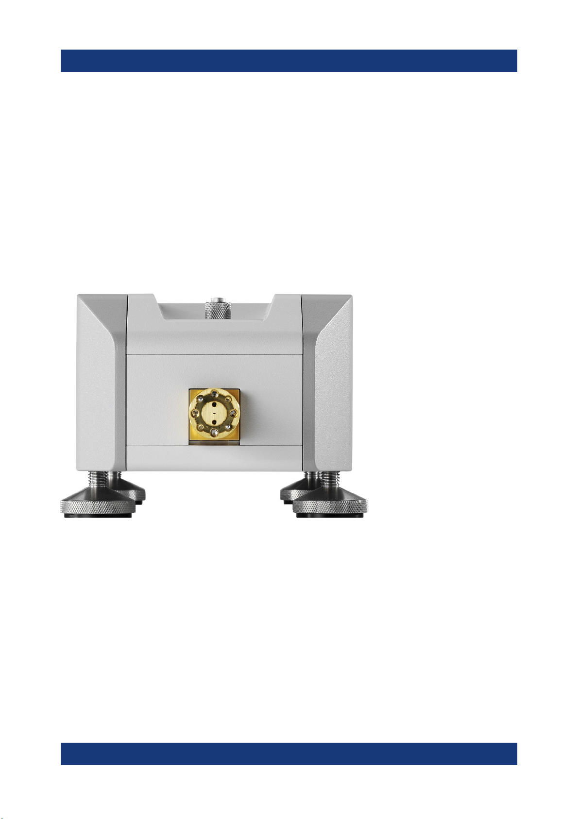
The test port with a mounted test port adapter is located at the front of the instrument. The device under test (DUT) has to be connected to the test port adapter.
Figure 4-1: Front of the converter R&S ZC330
The precision waveguide flange of the test port adapter, which is compatible to
standard IEEE 1785, consists of an outer ring and a protruding inner contacting
surface with the waveguide. On the outer ring there are four UNC 4-40 threads,
two dowels and two holes as counterparts of the DUT dowels (see Figure 4-2).
Two additional holes in the inner flange surface allow the insertion of precision
dowels (delivered with the converter). To enhance the accuracy of the connection,
use additional dowels if the flange of the DUT also has holes for them.
13Getting Started 1177.5156.02 ─ 05
R&S®ZCxxx
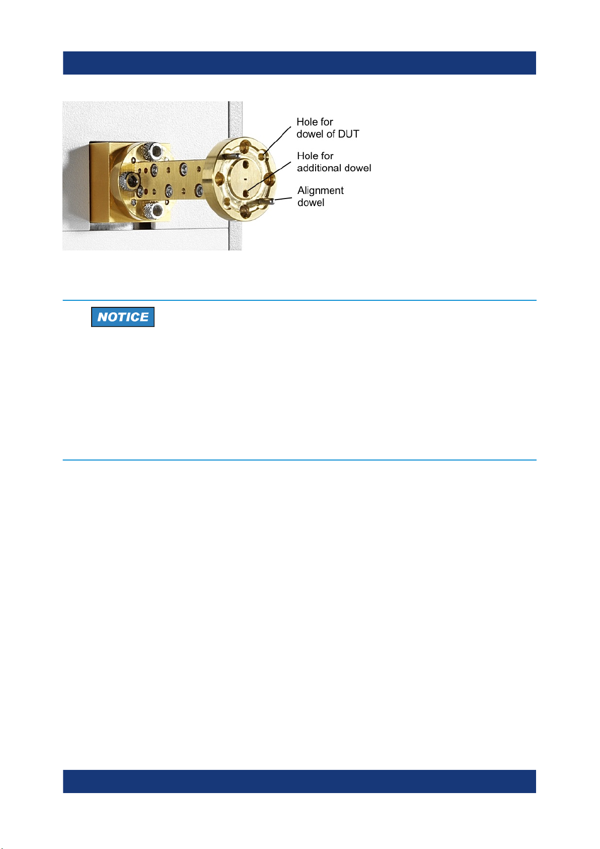
Figure 4-2: Test port adapter of R&S ZC330
Risk of damaging waveguide flanges
Instrument tour
Test port adapter (waveguide flange)
The waveguide flanges of the converter and of the test port adapters must
be protected against scratches and other mechanical damages. Furthermore the waveguides must be shielded from dust.
Protect the waveguide flange of the converter by leaving the test port
adapter mounted. When the converter is not in use, slip a protective cap
onto the adapter.
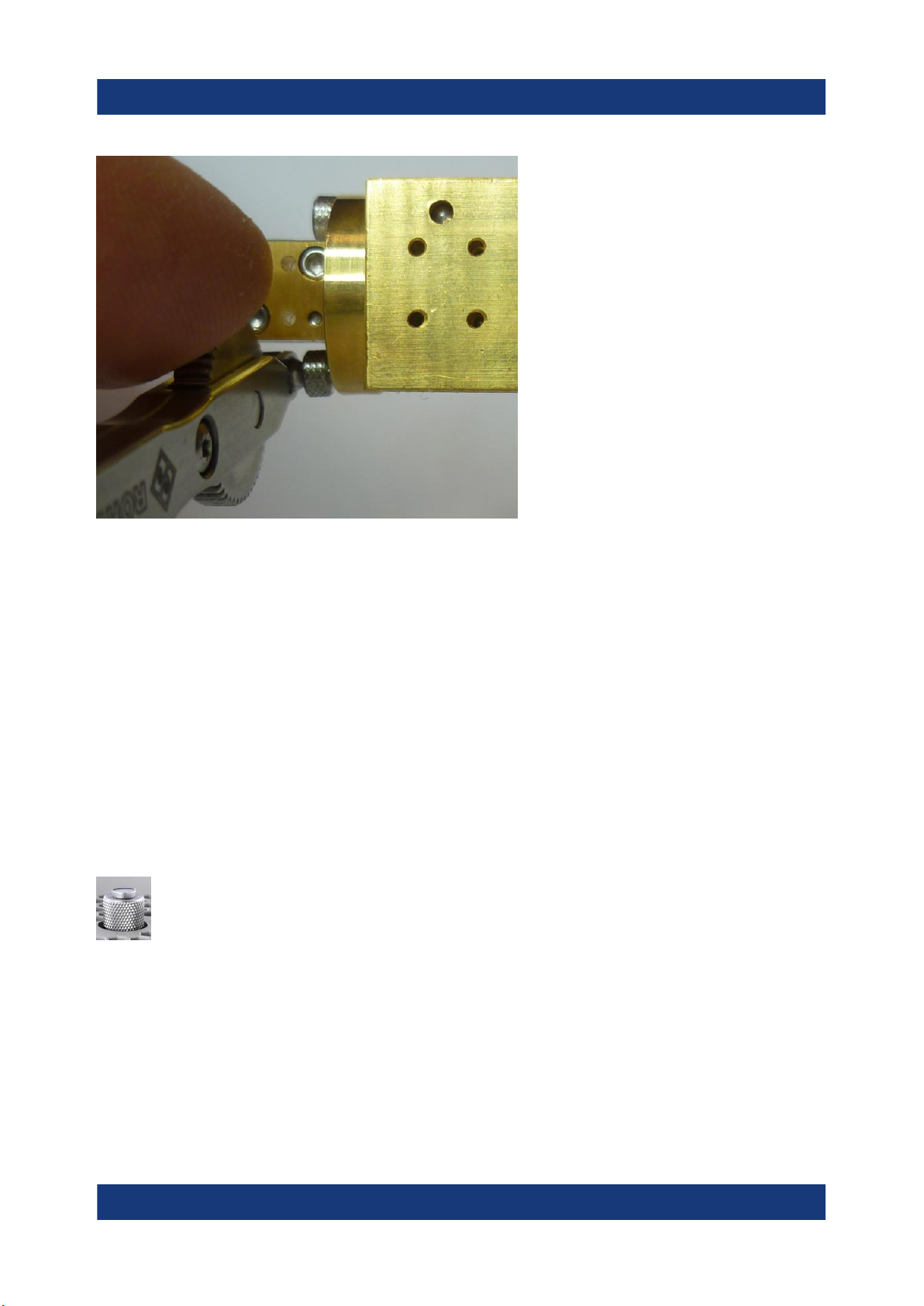
Mounting a DUT
Mount the DUT to the test port adapter at the front of the converter. Use the included screws and hex ball driver. For higher precision, a torque-controlled hex ball
driver R&S ZV-Z1000 is available as an accessory (order number 1314.5467.02).
An angled hex ball driver facilitates working in the tight space between rear side
of the test port adapter flange and converter front side (see Figure 4-3).
Rohde&Schwarz offers three variants:
●
R&S ZCAW (order number 1175.1960.00) without torque control
●
R&S ZCTW with 0.58 N·m torque limit (order no. 1175.2014.02)
●
R&S ZCTW with 0.2 N·m torque limit (order no. 1175.2014.03)
14Getting Started 1177.5156.02 ─ 05
R&S®ZCxxx
Instrument tour
Output power-adjusting knob
Figure 4-3: Angled hex ball driver R&S ZCAW (accessory)
For precision calibrations and measurements, use the inner dowels at the test
port adapter. A tight and accurate connection is important to ensure precise measurement results.
For a two- or n-port measurement, setup converters and DUT have to be aligned
accurately, using the adjustable instrument feet. Use a bubble level for proper
alignment.
4.2 Output power-adjusting knob
The knurled knob steeped in the upper surface of the converter housing
adjusts an integrated variable mechanical attenuator that allows you to
control the output power at the waveguide test port manually. Such an
attenuator is available for all R&S ZCxxx converters, except the R&S ZC90,
R&S ZC90E, R&S ZC110 and RPG ZC1100.
Turning the knob clockwise reduces the output power while turning it counterclockwise increases the output power. The minimum power is reached at the stop
in clockwise direction while maximum power is reached at the stop in counterclockwise direction. The knob cannot be turned so far in counter-clockwise sense
that it protrudes the upper surface of the R&S ZCxxx. So there is no danger that
the mechanism of the variable attenuator is damaged when the frequency con-
15Getting Started 1177.5156.02 ─ 05
 Loading...