

Rohde&Schwarz R&S®VENICE User Manual
R&S®VENICE S800/812/824-G2
User Manual
2906.0984.02
Version 11

VENICE S
© 2022 Rohde & Schwarz GmbH & Co. KG
Hanomaghof 4, 30449 Hanover, Germany
Phone: +49-511-67807-0
Support: https://www.rohde-schwarz.com/support
Internet: https://www.rohde-schwarz.com
Subject to change – Data without tolerance limits is not binding.
R&S® is a registered trademark of Rohde & Schwarz GmbH & Co. KG.
Trade names are trademarks of the owners.
Throughout this manual, products from Rohde & Schwarz are indicated without the ® symbol,
e.g. R&S®VENICE S is indicated as VENICE S.
2
User Manual | 2906.0984.02 - 11

VENICE S
Contents
General .............................................................................................................7
About this Documentation....................................................................................................... 8
Required Reading ................................................................................................................8
Target Group ........................................................................................................................ 8
Additional Documentation .................................................................................................... 8
Safety ................................................................................................................9
For your Safety ....................................................................................................................... 10
General Notes ......................................................................................................................... 11
Product Description ......................................................................................13
Function .................................................................................................................................. 14
Models ..................................................................................................................................... 15
Features................................................................................................................................... 16
Channel Configuration ........................................................................................................ 16
Workflow-based Metadata .................................................................................................. 17
Audio Routing ..................................................................................................................... 24
Image Processing ............................................................................................................... 24
Timecode ............................................................................................................................ 25
Play After Write .................................................................................................................. 26
Type Plate and Serial Number ............................................................................................... 27
Type Plate .......................................................................................................................... 27
Serial Number .................................................................................................................... 28
Scope of Delivery ................................................................................................................... 29
The Front of the System ........................................................................................................ 30
Front Plate .......................................................................................................................... 30
Chassis Front ..................................................................................................................... 30
Left Control Panel ............................................................................................................... 31
Right Control Panel ............................................................................................................ 31
Hard Drives ........................................................................................................................ 32
The Rear of the System..........................................................................................................34
Back Panel ......................................................................................................................... 34
LTC In/Out .......................................................................................................................... 35
Power Supply Unit .............................................................................................................. 36
Power Supply Indicator ...................................................................................................... 36
Out- or Input of Primary/Secondary Control Signals .......................................................... 37
Downconvert Video Output ................................................................................................ 38
In-/Output of Digital Video Signals ..................................................................................... 39
Network Interface Card (NIC) Connectors.......................................................................... 43
NIC Indicator ...................................................................................................................... 43
Inside the System ................................................................................................................... 45
System Cover ..................................................................................................................... 45
Cooling Fan Assembly ....................................................................................................... 46
Cooling Fans ...................................................................................................................... 47
Rescue Stick ...................................................................................................................... 48
User Manual | 2906.0984.02 - 11
3

VENICE S
Pin Assignment ...................................................................................................................... 49
HD Sub-D Connector (LTC In/Out) .................................................................................... 49
RJ45 Connector ................................................................................................................. 50
Serial Connector ................................................................................................................. 51
Video Connector .................................................................................................................52
Lynx CBL-AES1604 Cable ................................................................................................. 54
Network Ports ......................................................................................................................... 55
VENICE S Server Ports (Information) ................................................................................ 55
VENICE S Server Ports (Configuration) ............................................................................. 59
VENICE S Client Ports (Information) .................................................................................. 61
VENICE S Client Ports (Configuration) .............................................................................. 63
Installation and Configuration ..................................................................... 65
Installing the System .............................................................................................................. 66
Starting the System ................................................................................................................ 70
Configuring the System ......................................................................................................... 71
Network Configuration ........................................................................................................ 71
Using a Static IP ................................................................................................................. 71
Using a Dynamic IP ............................................................................................................ 71
Integrating Software Service .............................................................................................. 72
System Update ...................................................................................................................72
Management Tool R&S®Device Manager ......................................................................... 72
Shutting Down the System .................................................................................................... 73
Operation ....................................................................................................... 75
Operating the System ............................................................................................................76
Usable Software and Protocols .......................................................................................... 76
VENICE UI ......................................................................................................................... 76
Playing Content .................................................................................................................. 77
Ingesting Content ...............................................................................................................77
Transforming Content ......................................................................................................... 78
File Management ................................................................................................................ 78
Configuring VENICE S Services ........................................................................................ 79
Configuring the Subtitles .................................................................................................... 82
Administration............................................................................................... 85
User Management................................................................................................................... 86
Changing the Passwords ................................................................................................... 86
Changing the User ID ......................................................................................................... 87
Adding Samba Users ......................................................................................................... 88
Creating a Backup Image ....................................................................................................... 89
Restoring the System............................................................................................................. 92
System Update ........................................................................................................................ 95
SNMP System Monitoring ...................................................................................................... 97
SNMP MIB files location ..................................................................................................... 97
Understanding SNMP Naming ........................................................................................... 97
Basic System Monitoring via SNMP ................................................................................... 98
Advanced System Monitoring via SNMP .......................................................................... 100
4
User Manual | 2906.0984.02 - 11

VENICE S
Integration into an IP Network ............................................................................................. 110
Preconditions .................................................................................................................... 110
General Network Settings ................................................................................................ 111
Installing the IP Software .................................................................................................. 114
Channel Configuration ...................................................................................................... 114
Activating the SMPTE 2110 IP Interfaces ........................................................................ 115
Configuring the PTP Sync Mode ...................................................................................... 116
Configuring the PTP Parameters ..................................................................................... 118
Configuring the NMOS Node Settings .............................................................................. 119
NMOS Stream Configuration ............................................................................................ 119
Maintenance .................................................................................................133
Safety Instructions ............................................................................................................... 134
Removing and Mounting the System Cover ...................................................................... 136
Removing the System Cover ............................................................................................ 136
Installing the System Cover .............................................................................................. 137
Replacing a Power Supply Unit ........................................................................................... 138
Replacing a Hot Swappable Hard Drive ............................................................................. 140
Replacing a Cooling Fan Assembly .................................................................................... 142
Replacing a Cooling Fan .................................................................................................. 143
Replacing the Internal USB Memory Key ........................................................................... 145
Working with the R&S Installer (RSI) .........................................................147
Types of RSI Packages ........................................................................................................ 148
Using an RSI ......................................................................................................................... 149
RSI Troubleshooting ............................................................................................................ 151
Logs .................................................................................................................................. 151
Error Codes ......................................................................................................................151
Transport ......................................................................................................155
Safety Notes .......................................................................................................................... 156
Packing the System..............................................................................................................157
Troubleshooting ..........................................................................................159
Safety First - For you and your System .............................................................................. 160
Troubleshooting External Connections ............................................................................. 161
Troubleshooting the Video Subsystem .............................................................................. 162
Troubleshooting a USB Device ........................................................................................... 163
Troubleshooting a Wet System ........................................................................................... 164
Troubleshooting Power Supply Units ................................................................................ 165
Troubleshooting Power Source Problems ........................................................................ 165
Power Supply Unit Problems ............................................................................................ 165
Troubleshooting Cooling Problems ................................................................................... 166
Troubleshooting Cooling Fans ......................................................................................... 166
Troubleshooting an Internal USB Key ................................................................................ 167
Restarting a Single Channel ................................................................................................ 168
Disk Space Limit ................................................................................................................... 169
Technical Data .............................................................................................171
Declaration of Conformity (CE) ........................................................................................... 183
Index .............................................................................................................185
User Manual | 2906.0984.02 - 11
5

VENICE S
6
User Manual | 2906.0984.02 - 11

General
This chapter includes the following section:
GeneralVENICE S
● "About this Documentation" (page 8)
User Manual | 2906.0984.02 - 11
7

General
About this Documentation
About this Documentation
This documentation informs you about the installation of the VENICE S hardware, a video server system by Rohde & Schwarz, its operation as well as all
connection possibilities. Furthermore, it describes maintenance tasks that
you may carry out on your own.
Required Reading
Each person who is responsible for installation, operation, maintenance or
setting of the system has to read and understand this manual.
Target Group
To use this manual you should have experience in handling video and
computer equipment.
When performing maintenance tasks on the hardware, you must be qualified
to work on, repair and test electrical equipment.
VENICE S
Additional Documentation
Following documents have to be heeded while working with VENICE S:
● Data Sheet
● Safety, Environment and Regulatory Information
● Software Integration Guide
● Supported File Formats for Software Version 3.5
● Supported File Formats for Software Version 4
The complete documentation can be downloaded from
https://gloris.rohde-schwarz.com after registering/logging in to access
restricted information. There you may find updated manuals and further
information as well.
8
User Manual | 2906.0984.02 - 11

Safety
SafetyVENICE S
This chapter is divided into the following sections:
● "For your Safety" (page 10)
● "General Notes" (page 11)
User Manual | 2906.0984.02 - 11
9

Safety
For your Safety
For your Safety
The product documentation helps you to use VENICE S safely and efficiently. Keep the product documentation in a safe place and pass it on to the
subsequent users. Use VENICE S only in its designated purpose as
described in the product documentation. Observe the performance limits and
operating conditions stated in the specification (data sheet).
Safety information is part of the product documentation. It warns you about
the potential dangers and gives instructions how to prevent personal injury or
damage caused by dangerous situations.
Safety information is provided as follows:
● In the "Basic Safety Instructions", safety issues are grouped according to
subjects.
● Throughout the documentation, safety instructions are provided when
you must pay attention during setup or operation.
Always read the safety instructions carefully. Make sure to fully comply with
them. Do not take risks and do not underestimate the potential danger of
small details such as a damaged power cable.
VENICE S
10
User Manual | 2906.0984.02 - 11

VENICE S
General Notes
Please observe the following general important notes:
● Computer hardware contains components that are sensitive to electro-
static discharge. If you touch them without precautionary measures, they
can be destroyed. Use a wrist strap connected to ground when
accessing electronic parts and take care of grounding the system. Avoid
touching the internal components of VENICE S whenever possible.
● Performance Loss:
VENICE S has been delivered to you fully preconfigured and optimized
for a real-time in- and output of video streams. Changing any of the
settings (e.g. the hardware, software and/or BIOS settings) may lead to a
loss of performance or may even render the system unusable. Reconfiguring VENICE S anew in most cases is a lengthy procedure. Modifications of settings i.e. BIOS settings shall be done with Rohde &
Schwarz.
● Data loss/Corrupt data
In the event of a power failure the device will be abruptly switched off.
This can result in corrupt data, loss of data, and equipment damage.
Connect the system to an uninterruptible power supply (UPS) redundantly on two phases.
● Third-party Software:
VENICE is built for the most demanding realtime operations. Third-party
software might have unpredictable influences to the overall performance
and stability of the system. Do not install any third-party software that
has not been tested and approved by Rohde & Schwarz on your system.
● Real-time performance:
Use only the optional internal storage or external storage solutions which
are tested and released by Rohde & Schwarz to store video and audio
data. Other storage locations and solutions will be too slow for real-time
operations.
● Storage capacity exceeded:
In case of a full storage performance losses may occur. Leave about 10
to 15 % of the overall main storage capacity empty of data for performance reasons.
● It is recommended to set up an e-mail notification, to ensure you get
informed when a hardware malfunction occurs.
Safety
General Notes
Authentication Security
To ensure the safety of systems connected in a network and/or to the
Internet, we highly recommend to change the default password on both the
VENICE S server as well as the on the web UI of R&S®Device Manager as
soon as the initial setup is completed.
For more information, see section "Changing the Passwords"
(page 86)
User Manual | 2906.0984.02 - 11
11

Safety
General Notes
VENICE S
12
User Manual | 2906.0984.02 - 11

Product Description
This chapter is divided into the following sections:
● "Function" (page 14)
● "Models" (page 15)
● "Features" (page 16)
● "Type Plate and Serial Number" (page 27)
● "Scope of Delivery" (page 29)
● "The Front of the System" (page 30)
● "The Rear of the System" (page 34)
● "Inside the System" (page 45)
● "Pin Assignment" (page 49)
● "Network Ports" (page 55)
Product DescriptionVENICE S
User Manual | 2906.0984.02 - 11
13

Product Description
Function
Function
VENICE S is a media server especially designed for studio production as
well as channel playout. It offers ingest, playout and transforming functions
in one single box. The open software structure allows to combine video and
IT workflows in broadcast environments.
In playout mode VENICE S assumes the role of a player. For a remote
controlled playout set VENICE S in VDCP or MOS mode via VENICE web
service or the R&S
In ingest mode VENICE S assumes the role of a recorder. For a remote
controlled ingest set VENICE S in FIMS or VDCP mode via VENICE web
service or the R&S
In transform mode VENICE S transforms video and audio material to
different file formats. If possible, the file conversion (transcoding) will be
performed in hardware at a faster render speed. For a remote controlled
transform set VENICE S in FIMS mode via VENICE web service or the
R&S
®
Device Manager.
®
Device Manager.
®
Device Manager.
VENICE S
For more information about the integration of VENICE S by VDCP, MOS,
FIMS and the VENICE web service please see the Software Integration
Guide, available at:
https://gloris.rohde-schwarz.com.
There's no graphical Desktop on the VENICE-S, so you got to talk to it via
either:
● text console on locally connected monitor and keyboard (front or rear
connectors)
● remote SSH console („Putty“ or „MobaX“ on Windows PC or laptop)
● remote R&S
®
Device Manager (via browser on Windows PC or laptop)
14
User Manual | 2906.0984.02 - 11

VENICE S
Models
Product Description
Models
The following models are available:
● VENICE S800 (no internal media storage)
● VENICE S812 (12 TB internal media storage)
● VENICE S824 (24 TB internal media storage)
User Manual | 2906.0984.02 - 11
15

Product Description
Features
Features
● On-air reliability: The entire system has no single point of failure due to
● SDI and IP functionality: Equipped with a new video I/O board,
● Flexible system design: VENICE S can be scaled to meet your require-
● UHD and HDR ready: VENICE S supports up to two UHD p60 channel
● Standard server platform: VENICE S uses a standard IT server whose
● Comprehensive software-based codec support: VENICE S minimizes
● Service-oriented architecture: FIMS and web services communica-
● Storage options: VENICE S can be equipped with up to 24 terabyte
VENICE S
the redundancy of every system-relevant component.
VENICE S offers SDI and IP functionality.
ments, no matter how many channels and how much storage capacity or
bandwidth you need.
(bidirectional) and eight HD p60 channels (bidirectional) and handles
HDR material with ease.
reliability and performance has proven itself a thousand times over in
data centers worldwide.
the need for transcoding by supporting a variety of software-based
codecs that can be expanded via future software updates.
tions allow the greatest possible interoperability, flexibility and integrability in the broadcast value chain. VENICE S is easy to integrate into
existing infrastructures and can be dynamically adapted to meet any
requirement.
internal RAID storage and connected to external storage solutions.
Channel Configuration
VENICE can be set to HD/SD or UHD-1 operation via the R&S®Device
Manager.
HD/SD:
● eight bidirectional HD/SD channels
● optional transform functionality per channel
● automatic aspect ratio conversion (ARC) with active format descriptor
(AFD) support
UHD:
● two bidirectional UHD-1 channel
● optional transform functionality
● one HD downconversion output per channel (locked to UHD-1 channel)
16
User Manual | 2906.0984.02 - 11
VENICE S
Workflow-based Metadata
VENICE S enables you to use the process of closed captioning (CC) and
subtitling (STL), so that it can be decoded and displayed on a television,
video screen, or other visual displays.
.
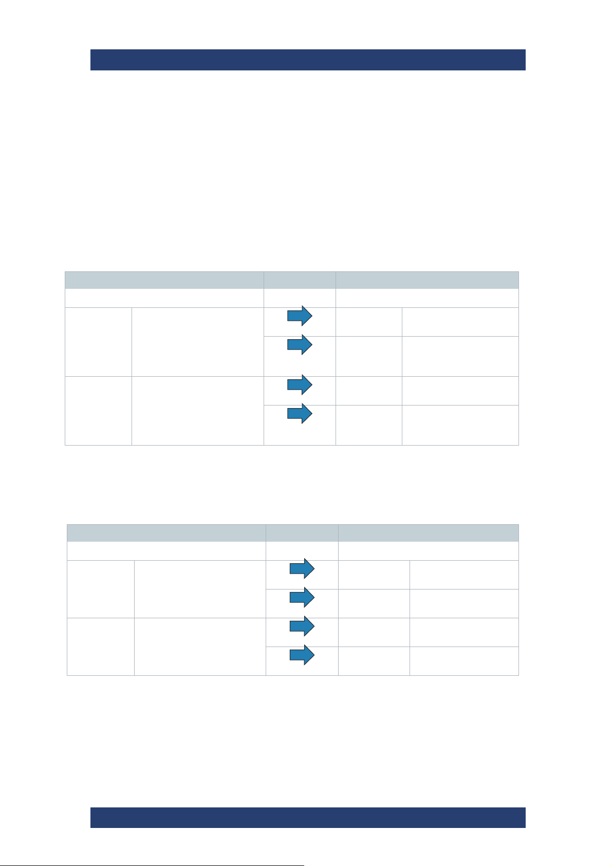
VBI-ANC Handling
VENICE S supports the read out of VBI (vertical blanking interval) information. VBI information will be converted to ANC on any output raster.
INPUT OUTPUT
ANC & VBI Closed Caption
PLAYOUT ANC Closed Caption
Product Description
Features
SD-SDI
V-Lines: 525
HD-SDI ANC Closed captioning (CEA-
1.particular case
INPUT OUTPUT
ANC & VBI Closed Caption
SD-SDI
V-Lines: 625
HD-SDI ANC OP-47 SD-SDI
VBI CEA-608 data
ANC CEA-608 data
ANC & VBI CEA-608 data
708) (CDP)
ANC CEA-608 data
VBI OP-42
ANC OP-47
ANC & VBI OP-47/42
1
SD-SDI
1
V-Lines: 625
HD-SDI ANC Closed captioning
SD-SDI
V-Lines: 625
HD-SDI ANC Closed captioning
PLAYOUT ANC Closed Caption
SD-SDI
V-Lines: 625
HD-SDI ANC OP-47
V-Lines: 625
ANC CEA-608 data
(SMPTE 334-1)
(CEA-708) (CDP)
(SMPTE 334-1)
ANC CEA-608 data
(SMPTE 334-1)
(CEA-708) (CDP)
(SMPTE 334-1)
ANC OP-47
(SMPTE 2031)
(SMPTE 2031)
ANC OP-47
(SMPTE 2031)
1.particular case
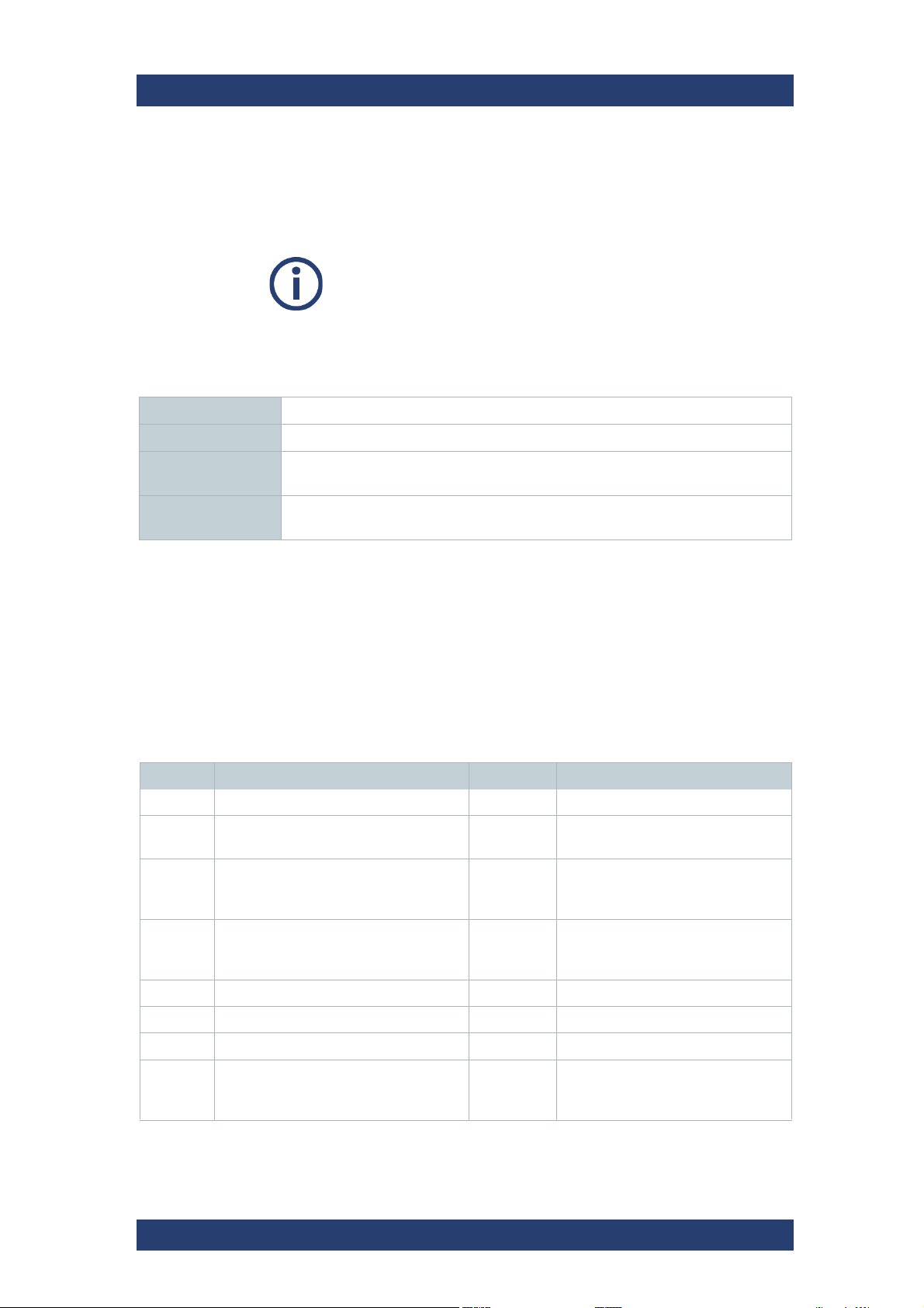
The following VBI information will be converted to ANC:
User Manual | 2906.0984.02 - 11
HD-SDI ANC OP-47
(SMPTE 2031)
17

Product Description
Features
VBI ANC (SMPTE 291)
WSS (Wide Screen Signaling,
ETSI EN 300 294)
VBI OP-42
(Teletext/Subtitles)
VENICE S
AFD (Active Format Description,
SMPTE 2016)
ANC OP-47
(SMPTE 2031)
Line 21 (VBI CEA-608 data)
(CC)
ANC CEA -608/708
(SMPTE 334-1)
ANC packages can be saved in QuickTime (CC only) and MXF OP1a files
according to SMPTE 436.
Closed Caption
VENICE S allows pass through of embedded closed captions, insertion from
closed caption files and SD/HD up and down conversion. Thereby SD closed
captions conforms to the CEA-608. HD closed captions uses CEA-608
captions encapsulated within CEA-708 packets.
VENICE S supports embedded closed caption information stored in QuickTime (MOV). It records embedded CEA-708 information from the incoming
SDI signal in digital SD and HD.
When writing QuickTime files (ingest or transform) the closed caption data
are preserved in the following order whereas the first type found is written
into the files:
1 CEA-708 ANC (digital)
2 CEA-608 ANC (digital)
By default it is a QuickTime CEA-708 track ('c708').
A closed caption track will only be added to QuickTime files if valid closed
caption data is detected on the first frame of the provided input or if writing of
®
such a track has been enforced in the R&S
®
software version 3.5), in the R&S
Device Manager (available with software
VENICE software (available with
version 4) or via VENICE web service command
configureCodecRequest.
Furthermore, closed captions are stored in MXF OP-1a files as defined in the
SMPTE 436M standard. The closed captions are preserved with a head and
tail trim. Then they can be played out to SDI again.
Multiple languages can be inserted into four data channels on line 21 from
separate closed caption files. The first and the second closed caption track
will be placed into field 1 of the video frame. If more tracks
will be necessary
closed caption information also can be written in a separate *.scc file. For
this additional scc 3 files have to be enabled in the video settings of the
®
Device Manager. Field 2 of a video frame then transfer closed caption
R&S
tracks three and four.
For playout purposes external *.scc files can be inserted to the SDI signal.
18
User Manual | 2906.0984.02 - 11

VENICE S
Product Description
Features
If transcoding one file format into another file format during ingest
as well as transcoding the closed caption information could be lost
with the following format: MXF (OP Atom, Sony XDCam IMX,
AS02, AS11, IMF).
Closed Captions cannot be lost with the following formats: MOV,
MXF (OP1a Generic, RDD09, Sony XDCam DV, XAVC) and
MPEG-2.
Subtitles
VENICE S allows pass-through of embedded subtitles, insertion from subtitle
files and SD/HD up and down conversion.
VENICE S supports embedded subtitling information in MXF OP1a files or
additional in separate *.stl files. Subtitles can be read and written according
to EBU Tech 3264-E.
For playout purposes, external *.stl files for multiple languages
can be
inserted into the SDI signal.
®
The subtitles configuration for VENICE is done in the R&S
Device Manager
tool. If the respective "Record Subtitle Type" is enabled in the Subtitle
Settings, the system automatically uses subtitles, if available. The "Subtitle
File Path" setting in the "VDCP Settings" section is used to specify the directory where the system looks for subtitle files.
For working instructions on how to perform these settings, see section "Configuring the Subtitles" on page 82.
Currently VENICE S supports Latin and Greek character sets.
Aspect Ratio
There are many technical issues while dealing with SD and HD content. SD
content can be available in 16:9 or 4:3. HD content is always 16:9. A broadcaster must be able to playout all three types of material and switch seamlessly between them all. The aspect ratio can be changed at various points
in the broadcast chain.
To get an optimal picture it is important that the format bring accurate information with it. Outside the US, WSS (Wide Screen Signaling) was sometimes used with SD signals to define the aspect ratio. The information was
stored on VBI line 20 for NTSC and line 23 for PAL. Meanwhile AFD has
replaced WSS for both, SD and HD material.
AFD (Active Format Description) describes the video picture in terms of the
aspect ratio and other characteristics of the active image within the coded
frame.
User Manual | 2906.0984.02 - 11
19
Product Description
VENICE S
Features
®
With one of the following values in the "AFD Data Mode" in the R&S
Device
Manager or via the VENICE web service it can be determined, if the existing
AFD data file should be used or if this data should be overwritten:
If transcoding one file format into another file format during ingest
as well as transcoding the AFD information could be lost with the
following format: MXF (OP Atom, Sony XDCam IMX, AS02, AS11,
IMF).
AFD data couldn‘t be lost with following formats: MXF (OP1a Generic, RDD09, Sony XDCam DV, XAVC) and MPEG-2.
Strip All AFD data is removed.
PassThrough The existing AFD data is passed through.
Generate The existing AFD data is passed through. If no AFD data is present, AFD data is
generated based on the current settings.
Replace The AFD data is always generated based on the current settings. Existing AFD
data is replaced.
The „AFD Reset Mode“ can used to determine whether the AFD overwrite
should be valid only for this clip or until further notice.
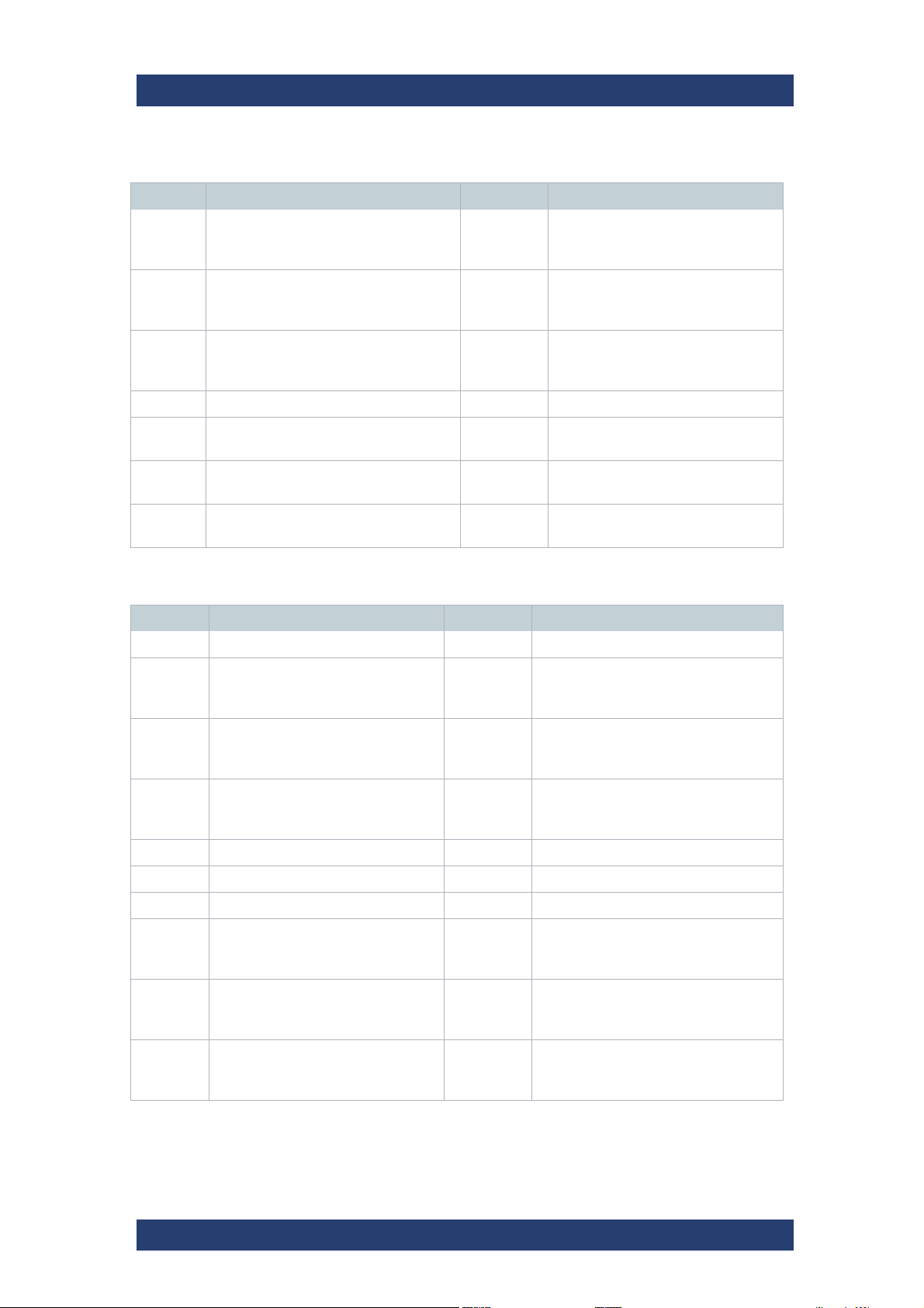
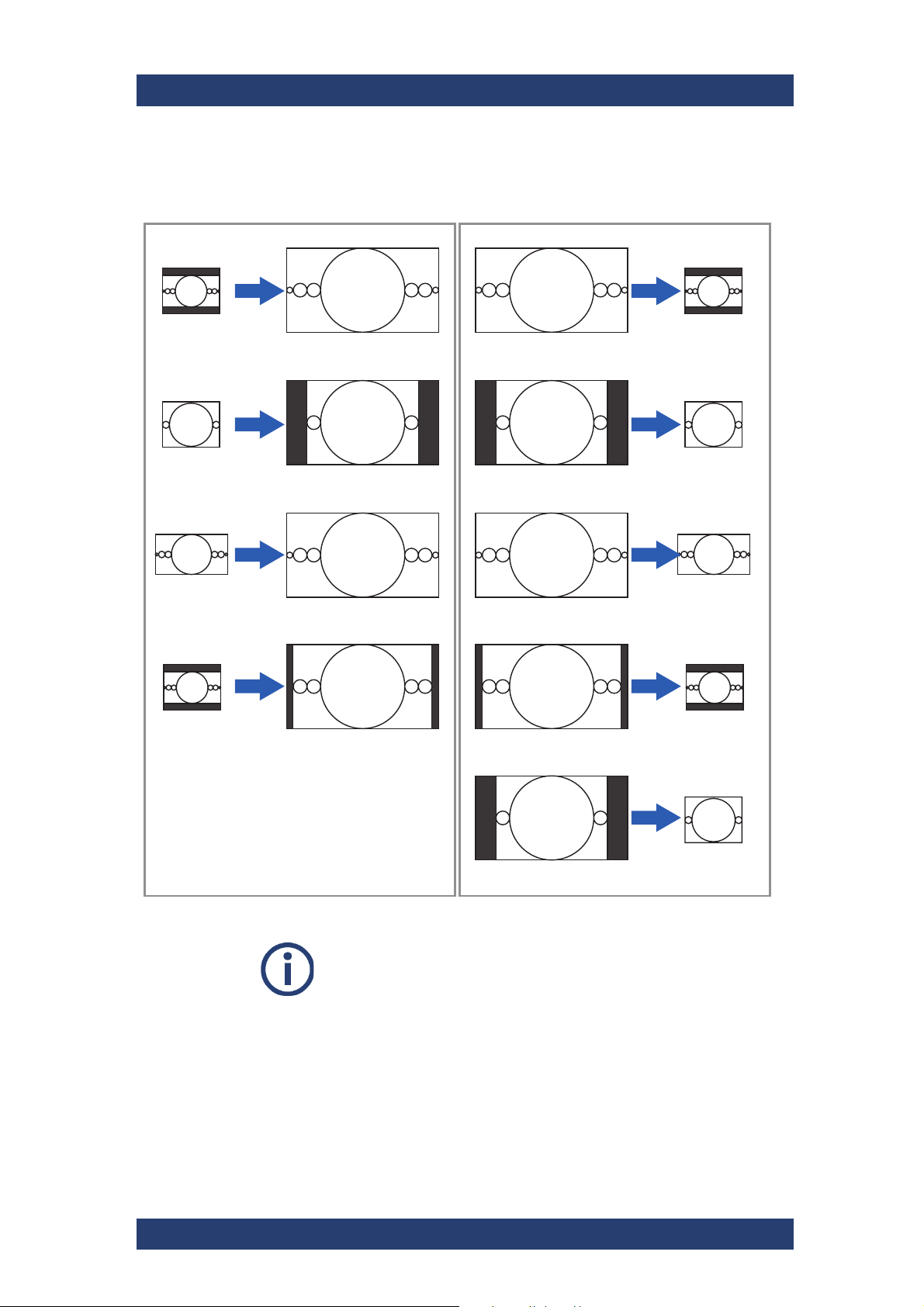
Supported Conversion Using AFD
VENICE S can be configured for SD, HD and UHD playout. So the server
supports many different clip-related aspect ratio conversions (ARC) as
shown in the following:
AFD In Input (4:3) AFD Out Output (16:9)
0001 Reserved - Invalid
0010 Letterbox 16:9 image,
at the top of the coded frame
0011 Letterbox 14:9 image,
at the top of the coded frame
0100 Letterbox image with an aspect ratio
greater than 16:9, vertically centered in
the coded frame
0101 Reserved - Invalid
0110 Reserved - Invalid
1000 Full frame 16:9 image,
the same as the coded frame
1011 Pillarbox 14:9 image,
horizontally centered in the coded
frame
0100 Letterbox image with an aspect ratio
greater than 16:9, vertically
centered in the coded frame
0111 Reserved - Invalid
1000 Full frame 4:3 image,
the same as the coded frame
20
1001 Pillarbox 4:3 image,
horizontally centered in the coded
frame
User Manual | 2906.0984.02 - 11
VENICE S
AFD In Input (4:3) AFD Out Output (16:9)
1001 Full frame 4:3 image,
the same as the coded frame
1010 Letterbox 16:9 image, vertically
centered in the coded frame with all
image areas protected
1011 Letterbox 14:9 image,
vertically centered in the coded frame
1100 Reserved - Invalid
1001 Pillarbox 4:3 image,
horizontally centered in the coded
frame
1010 Full frame 16:9 image,
with all image areas protected
1011 Pillarbox 14:9 image,
horizontally centered in the coded
frame
Product Description
Features
1101 Full fame 4:3 image,
with alternative 14:9 center
1110 Letterbox 16:9 image,
with alternative 14:9 center
1111 Letterbox 16:9 image,
with alternative 4:3 center
AFD In Input (16:9) AFD Out Output (4:3)
0001 Reserved - Invalid
0010 Full frame 16:9 image,
the same as the coded frame
0011 Pillarbox 14:9 image,
horizontally centered in the coded
frame
0100 Letterbox image with an aspect ratio
greater than 16:9, vertically
centered in the coded frame
0101 Reserved - Invalid
0110 Reserved - Invalid
1101 Pillarbox 4:3 image
1110 Full frame 16:9 image
1111 Full frame 16:9 image
1010 Letterbox 16:9 image, vertically
centered in the coded frame with all
image areas protected
1011 Letterbox 14:9 image,
vertically centered in the coded frame
0100 Letterbox image with an aspect ratio
greater than 16:9, vertically centered in
the coded frame
0111 Reserved - Invalid
1000 Full frame 16:9 image,
the same as the coded frame
1001 Pillarbox 4:3 image,
horizontally centered in the coded
frame
1010 Full frame 16:9 image, with all
image areas protected
1010 Letterbox 16:9 image,
vertically centered in the coded frame
with all image areas protected
1000 Full frame 4:3 image,
the same as the coded frame
1010 Letterbox 16:9 image, vertically
centered in the coded frame with all
image areas protected
User Manual | 2906.0984.02 - 11
21

Product Description
Features
AFD In Input (16:9) AFD Out Output (4:3)
1011 Pillarbox 14:9 image,
horizontally centered in the coded
frame
1100 Reserved - Invalid
1011 Letterbox 14:9 image, vertically
centered in the coded frame
VENICE S
1101 Pillarbox 4:3 image,
with alternative 14:9 center
1110 Full frame 16:9 image,
with alternative 14:9 center
1111 Full frame 16:9 image,
with alternative 4:3 center
1101 Full frame 4:3 image,
with alternative 14:9 center
1110 Letterbox 16:9 image,
with alternative 14:9 center
1111 Letterbox 16:9 image,
with alternative 4:3 center
22
User Manual | 2906.0984.02 - 11
VENICE S
AFD = 1010
AR = 16:9
AFD = 1001
AR = 16:9
AFD = 1000 or 1010
AR = 16:9
AFD = 1011
AR = 16:9
AFD = 1000 or 1010
AR = 16:9
AFD = 1001
AR = 16:9
AFD = 1000 or 1010
AR = 16:9
AFD = 1011
AR = 16:9
AFD = 1111
AR = 16:9
AFD = 1010
AR = 4:3
AFD = 1000 or 1001
AR = 4:3
AFD = 1000 or 1010
AR = 16:9
AFD = 1011
AR = 4:3
AFD = 1010
AR = 4:3
AFD = 1001
AR = 4:3
AFD = 1000 or 1010
AR = 16:9
AFD = 1011
AR = 4:3
AFD = 1001
AR = 4:3
HD to SDSD to HD
3
9
P
9
3
9
9
F
3
Product Description
Features
In the following figure represent the most common conversions.
Full Frame 16:
Letterbox 16:
Pillarbox 4:
Full Frame 14:
Full Frame 4:3
Full Frame 16:
At any time AFD values might be overwritten with the VENICE web service
command ActiveFormatBase. This setting is also possible in the
R&S
material if output format and the format of the video material are different.
Therefor the following parameter are available:
illarbox 14:9
Letterbox 14:
Incorrectly set AFD‘s are ignored.
®
Device Manager. Furthermore you can scale and resize the video
ull Frame 4:
User Manual | 2906.0984.02 - 11
23

Product Description
Features
Off The material will maintain its original size.
Box The original material will be scaled to its maximum allowable width
Crop The images will be scaled to their maximum allowable width or
Fit The aspect ratio will not be preserved. The resulting images will be
VENICE S
or height so that no information gets lost. If the aspect ratio is
different, you will receive black bars in the output.
height so that you receive a full image at the output. If the aspect
ratio is different, parts of the images will be cropped.
stretched or compressed if the aspect ratio is different and you will
always receive a full image in the output.
Active
Format
Based
The scaling will be performed based on the "Supported Conversion
Using AFD" on page 20.
Audio Routing
The R&S®Device Manager allows an easy audio routing of every video
channel.
DolbyE
VENICE S supports the pass trough of DolbyE audio. Thereby DolbyE tracks
will be handled as PCM audio. For example: if an MXF file has 8 channels of
PCM audio, it is possible that the first two channels (1 and 2) transfer DolbyE
while the other channels (3 -6) transfer normal PCM audio. It is also possible
the other way around, so that the first six channels transfer PCM audio and
the last two channels DolbyE.
Image Processing
VENICE supports upscaling during playout and transform operations.
24
User Manual | 2906.0984.02 - 11

VENICE S
480i29.97
Product Description
OUTPUT
480i29.97
576i25
720p50
720p59.94
1080p25
1080p/9.97
1080i25
1080p50
x x
1080i29.97
Features
1080p59.94
2160p50
2160p59.94
576i25
720p50
720p59.94
1080p25
1080p29.97
1080i25
INPUT
1080p50
1080i29.97
1080p59.94
2160p50
2160p59.94
x x
x x x x
x x x x
x x x x
x x x x x
x x
x x x x
x x
x x x x
x x x x
x x x x
Timecode
VENICE S supports a wide range of timecode types:
● Internal
● Generic (Timecode of media file)
● LTC (Longitudinal Timecode)
● VITC (Vertical Interval Timecode)
● VTRTC (RS-422 Timecode)
● DVITC (Digital Vertical Interval Timecode
● DLTC (Digital Longitudinal Timecode)
● Time of day
On video tapes the VITC is basically stored for each frame in one video line
of the vertical blanking interval. While the LTC is recorded along the tape,
mostly for this, an audio track is used. In opposite to VITC, the LTC can be
read out during a fast forward and written later. Certainly during a still image
(paused) or during a slow forward the LTC can not be read out. With VITC
it‘s possible.
User Manual | 2906.0984.02 - 11
25

Product Description
Features
DLTC and DVITC is inserted in the vertical blanking interval of the SDISignal. It won’t be published in the video image. DVITC replaces the previously used VITC of analog systems. DVITC will be recorded most preferably
in line 9 and 10 of the SDI signal at the output of MAZ devices.
VTRTC (RS-422) is a via RS-422 transferred timecode of a controlled video
source.
Time of day is the actual time of the device.
Play After Write
The automated play after write functionality allows a true visual quality
check. It reads the open file being currently recorded directly from the disk.
The operator can see the file and can judge its quality directly after the video
has passed the encoding process and has been written to the storage.
VENICE S
Please note that for the play after write feature an additional channel for playout is needed. Furthermore, the ingest and playout
channels need to be on the same VENICE server.
26
User Manual | 2906.0984.02 - 11
VENICE S
Typ e pl at e
Type Plate and Serial Number
The serial number of the system is located on the type plate.
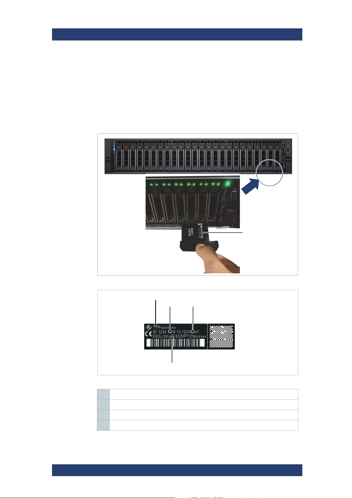
Type Plate
The type plate itself is located on the slide-out panel (information tag) which
can be accessed on the front of the system (bottom right).
Product Description
Type Plate and Serial Number
Location of the type plate on the slide-out panel
1
23
4
Type plate
1 Type
2 Article number
3 Serial number, see also "Serial Number" (page 28)
4 Product description
2
User Manual | 2906.0984.02 - 11
27
Product Description
Type Plate and Serial Number
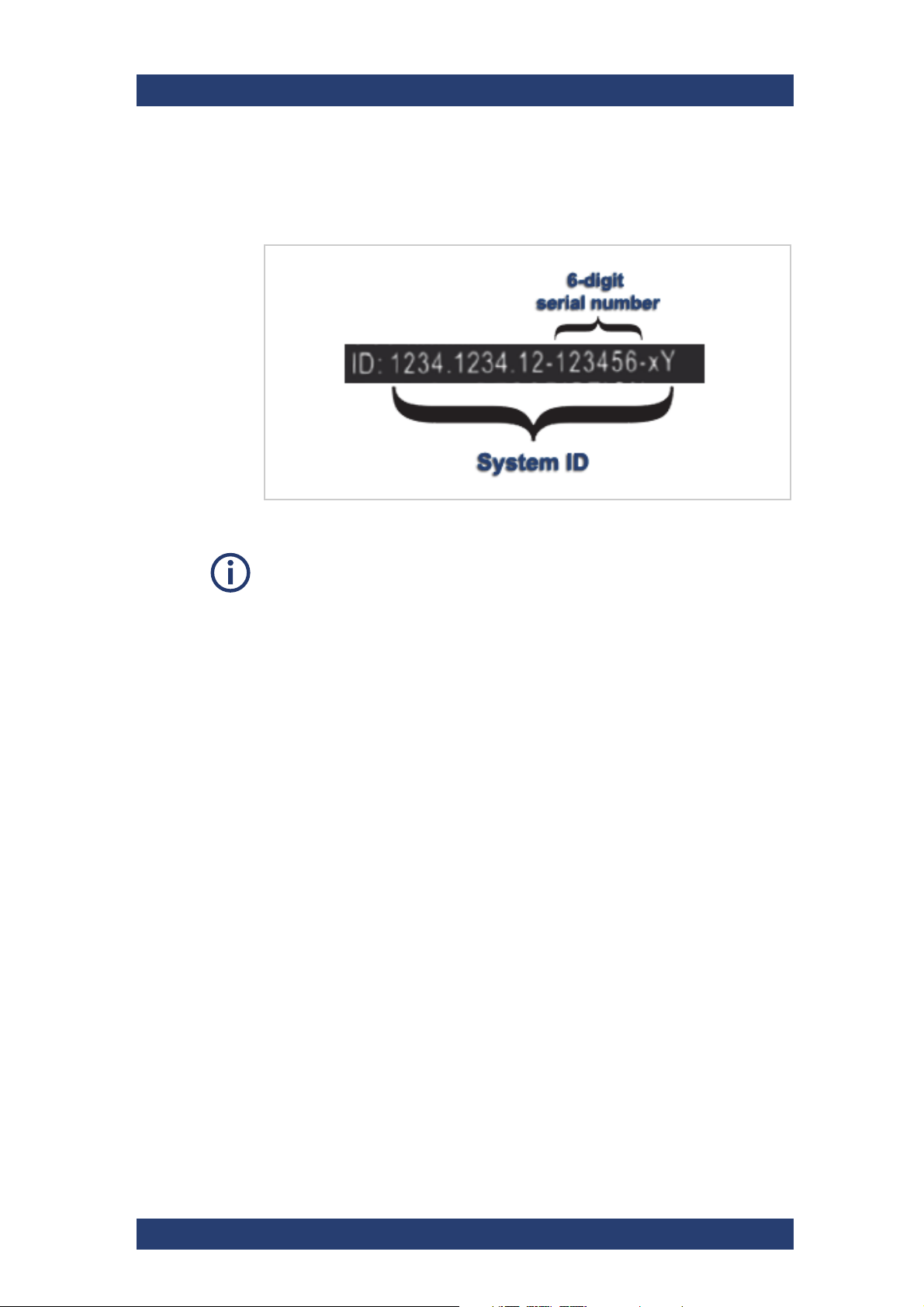
Serial Number
The serial number is part of the system ID. It is the 6-digit number that
comes after the article number:
Serial number as part of the system ID
VENICE S
This 6-digit serial number is used as password when logging in to:
● R&S
● VENICE S server (username: "root")
● iDRAC login (username: "root"). For systems built after April 2022
®
Device Manager web frontend (username: "administrator")
prepend "rs" to the beginning of the serial number (e.g "rs123456").
28
User Manual | 2906.0984.02 - 11

VENICE S
Scope of Delivery
The following components are included:
● VENICE S chassis
● Rack mount kit
● Cable management kit
● Power cable (rack)
● 2x SR SFP+ 10GbE optical transceiver
● 8x SDI 3G SFP bundle: SDI 3G combined input and output SFPs for 8
bidirectional HD/SDI channels (includes 4x 3G dual receiver and 4x 3G
dual transmitter)
● Product documentation
Optional:
● 2x VENICE accessory kit: 8x HD-BNC to BNC adapter cables, 4x RJ45
to DB9-adapter cables (RS422), 1x HD-D-SUB 26 male to 8 x XLR
female/male breakout cables.
Product Description
Scope of Delivery
User Manual | 2906.0984.02 - 11
29
Product Description
12 3
4
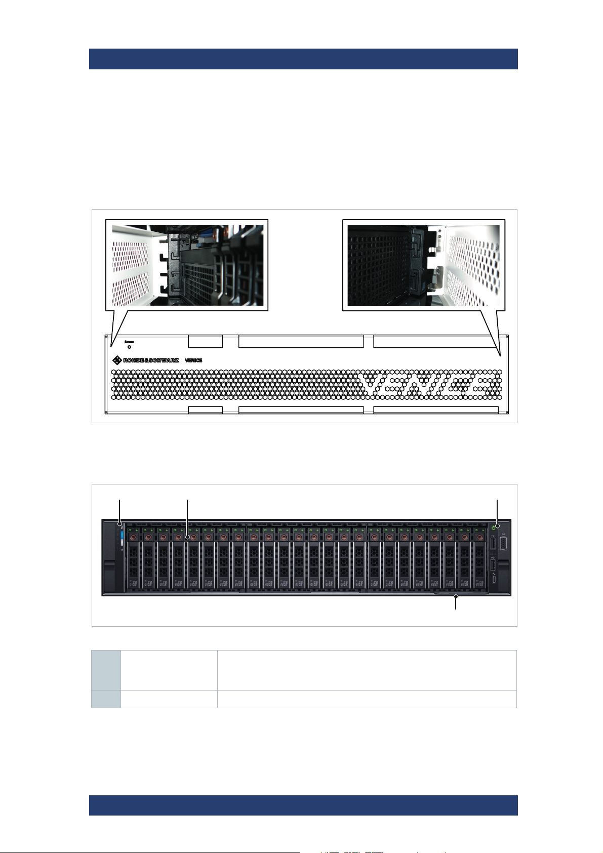
The Front of the System
The Front of the System
Front Plate
The front plate covers all operation items and the disk array. It is attached on
mounting on the left and on the right side in the front.
VENICE S
Front plate
Chassis Front
Chassis front
1 Left control panel Contains system health and system ID, status LED and optional iDRAC
Quick Sync 2 (wireless).
For more information see chapter “Left Control Panel” on page 31
2 Hard drives Up to 30 2.5-inch hot-swappable hard drives.
30
User Manual | 2906.0984.02 - 11
 Loading...