

Rohde&Schwarz R&S®TSME6 User Manual
R&S®TSME6
Ultracompact Drive Test Scanner
User Manual
(a00Q2)
4900003302
Version 06

This manual applies to the following R&S®TSME6 models and options:
●
R&S®TSME6 (4900.0004.02)
●
Block IQ data R&S®TSME6-K10 (4900.2459.02)
●
WCDMA scanning R&S®TSME6-K21 (4900.2188.02)
●
CDMA2000® scanning R&S®TSME6-K22 (4900.2165.02)
●
GSM scanning R&S®TSME6-K23 (4900.2194.02)
●
1xEVDO Rev. A scanning R&S®TSME6-K24 (4900.2142.02)
●
CW scanning R&S®TSME6-K25 (4900.2242.02)
●
TETRA scanning R&S®TSME6-K26 (4900.2142.02)
●
RF power scan R&S®TSME6-K27 (4900.2120.02)
●
WiMAX™ scanning R&S®TSME6-K28 (4900.2136.02)
●
LTE scanning R&S®TSME6-K29 (4900.2171.02)
●
LTE MIMO 2x2, 4x2, 4x4 R&S®TSME6-K30 (4900.2113.02)
●
LTE eMBMS scanning R&S®TSME6-K32 (4900.2288.02)
●
NB-IoT/Cat NB1 scanning R&S®TSME6-K34 (4900.2207.02)
●
LTE-M scanning R&S®TSME6-K35 (4900.2465.02)
●
C-V2X LTE scanning R&S®TSME6-K36 (4900.2707.02)
●
Automatic Channel Detection R&S®TSME6-K40 (4900.2259.02)
●
5G NR scanning R&S®TSME6-K50 (4900.2436.02)
●
5G NR scanning add-on R&S®TSME6-K51 (4900.2488.02)
●
BTS PE Enabler R&S®TSME6-K80 (4900.2442.02)
© 2022 Rohde & Schwarz GmbH & Co. KG
Muehldorfstr. 15, 81671 Muenchen, Germany
Phone: +49 89 41 29 - 0
Email: info@rohde-schwarz.com
Internet: www.rohde-schwarz.com
Subject to change – data without tolerance limits is not binding.
R&S® is a registered trademark of Rohde & Schwarz GmbH & Co. KG.
Trade names are trademarks of the owners.
4900.0033.02 | Version 06 | R&S®TSME6
Throughout this manual, products from Rohde & Schwarz are indicated without the ® symbol , e.g. R&S®TSME6 is indicated as
R&S TSME6.

R&S®TSME6
2.1.1 Getting started manual.................................................................................................. 11
2.1.2 User manuals and help..................................................................................................11
2.1.3 Tutorials.........................................................................................................................11
2.1.4 Basic safety instructions................................................................................................11
Contents
Contents
1 Safety and regulatory information........................................................7
1.1 Safety instructions........................................................................................................7
1.2 Labels on the product...................................................................................................9
1.3 Korea certification class B......................................................................................... 10
2 Welcome................................................................................................11
2.1 Documentation overview............................................................................................11
2.1.5 Brochures...................................................................................................................... 11
2.1.6 Application notes, application cards, white papers, etc.................................................12
2.2 Key features.................................................................................................................12
3 Getting Started..................................................................................... 13
3.1 Preparing for use........................................................................................................ 13
3.1.1 Unpacking and checking............................................................................................... 13
3.1.2 Setting up indoors......................................................................................................... 13
3.1.2.1 Placing the product on a bench top...............................................................................13
3.1.2.2 Mounting the product in a rack......................................................................................13
3.1.3 Considerations for test setup........................................................................................ 15
3.1.4 Connecting to power..................................................................................................... 16
3.1.4.1 Connecting to a vehicle DC power supply via cigarette lighter..................................... 16
3.1.4.2 Connecting to the vehicle power supply via terminal.................................................... 16
3.1.4.3 Connecting to an AC power supply...............................................................................17
3.1.5 Putting into operation.................................................................................................... 17
3.1.5.1 Setting up the LAN connection to the host PC..............................................................18
3.1.5.2 Connecting external devices......................................................................................... 23
3.1.5.3 Connecting a kensington lock....................................................................................... 24
3.1.5.4 Enabling untethered dead reckoning............................................................................ 25
3.1.6 Connecting multiple R&S TSME6s to one host PC.......................................................25
3.1.6.1 Using two R&S TSME6s in parallel...............................................................................26
3User Manual 4900.0033.02 ─ 06

R&S®TSME6
3.1.6.2 LTE MIMO setups with two R&S TSME6s.................................................................... 26
3.1.6.3 LTE MIMO setups with four R&S TSME6s....................................................................29
3.1.7 Connecting R&S TSME6 with R&S TSMA6/6B-BP...................................................... 32
3.1.8 Switching on or off R&S TSME6................................................................................... 32
3.1.9 Connecting the R&S TSME6 to a software application for the first time....................... 32
3.2.1 Front panel view............................................................................................................35
3.2.2 Rear panel view............................................................................................................ 36
Contents
3.2 Instrument tour............................................................................................................35
4 Option concept.....................................................................................40
4.1 Technology options.................................................................................................... 40
4.2 Band options............................................................................................................... 41
4.3 Licensing..................................................................................................................... 41
4.4 Option sharing concept..............................................................................................42
5 Vibration-proofed stacking................................................................. 43
5.1 Cascading R&S TSMA6/6B and R&S TSME6............................................................43
5.2 Connecting R&S TSMA6/6B-BP with R&S TSME6 and R&S TSMExxDC...............44
6 Configuring the R&S TSME6...............................................................46
6.1 Using the R&S TSME device manager...................................................................... 46
6.1.1 Obtaining device information - "Device Info".................................................................47
6.1.2 Changing IP addresses - "Network Configuration"........................................................50
6.1.3 Installing and managing software license keys - "Options"...........................................51
6.1.4 Configuring measurement bands - "Band Configuration"............................................. 53
6.1.5 Obtaining firmware and correction data updates - "Updates"....................................... 55
6.1.6 Aligning R&S TSME6 manually - "Self Alignment"........................................................56
6.1.7 Configuring downconverter R&S TSME30DC/TSME44DC - "Downconverter Configura-
tion"............................................................................................................................... 57
6.2 Interacting with R&S ROMES, R&S NESTOR, and R&S ViCom..............................59
6.2.1 Interacting with R&S ROMES....................................................................................... 59
6.2.2 Interacting with R&S NESTOR......................................................................................60
6.2.3 Interacting with R&S ViCom..........................................................................................60
7 Troubleshooting................................................................................... 62
7.1 Guide to solve instrument connection problems.................................................... 62
4User Manual 4900.0033.02 ─ 06

R&S®TSME6
Contents
7.2 Solving other miscellaneous problems.................................................................... 65
7.3 Contacting customer support....................................................................................69
8 Transporting.........................................................................................70
9 Maintenance, storage and disposal................................................... 71
9.1 Cleaning....................................................................................................................... 71
9.2 Storage.........................................................................................................................71
9.3 Disposal....................................................................................................................... 71
Annex.................................................................................................... 73
A Available cellular bands...................................................................... 73
Index......................................................................................................80
5User Manual 4900.0033.02 ─ 06

R&S®TSME6
Contents
6User Manual 4900.0033.02 ─ 06

R&S®TSME6
Safety and regulatory information
Safety instructions
1 Safety and regulatory information
The product documentation helps you use the product safely and efficiently. Follow the
instructions provided here and in the following chapters.
Intended use
The R&S TSME6 is intended for efficient drive and walk tests with a maximum degree
of freedom and upgradeability. With the ultracompact design and multiband and multitechnology support for simultaneous measurements, the scanner fulfills all requirements for a state-of-the-art measurement tool.
Observe the operating conditions and performance limits stated in the data sheet.
Where do I find safety information?
Safety information is part of the product documentation. It warns you of potential dangers and gives instructions on how to prevent personal injury or damage caused by
dangerous situations. Safety information is provided as follows:
●
In Chapter 1.1, "Safety instructions", on page 7. The same information is provided in many languages as printed "Safety Instructions". The printed "Safety
Instructions" are delivered with the product.
●
Throughout the documentation, safety instructions are provided when you need to
take care during setup or operation.
1.1 Safety instructions
Products from the Rohde & Schwarz group of companies are manufactured according
to the highest technical standards. To use the products safely, follow the instructions
provided here and in the product documentation. Keep the product documentation
nearby and offer it to other users.
Use the product only for its intended use and within its performance limits. Intended
use and limits are described in the product documentation such as the data sheet,
manuals and the printed "Safety Instructions". If you are unsure about the appropriate
use, contact Rohde & Schwarz customer service.
Using the product requires specialists or specially trained personnel. These users also
need sound knowledge of at least one of the languages in which the user interfaces
and the product documentation are available.
Never open the casing of the product. Only service personnel authorized by
Rohde & Schwarz are allowed to repair the product. If any part of the product is damaged or broken, stop using the product. Contact Rohde & Schwarz customer service at
http://www.customersupport.rohde-schwarz.com.
7User Manual 4900.0033.02 ─ 06

R&S®TSME6
Safety and regulatory information
Safety instructions
Operating the product
The product is intended for mobile use. The maximum weight of the product is provided in the data sheet. If the product casing is not waterproof, use an adequate weather
protection to carry the product outdoors with you.
When using the product in a vehicle or aircraft, make sure that the product is properly
secured. If stacking is possible, secure the whole stack of products so that they cannot
fall over and cause injury.
Observe the ambient conditions such as altitude, operating temperature and climatic
loads; see the data sheet.
Due to their exposed location, mobile communications systems are at risk of damage
from lightning. This also poses a risk to persons nearby. Vehicles carrying mobile communications systems require an electrically conductive body, a grounded antenna and
also equipotential bonding that includes the cables routed into the vehicle.
Connecting to power
The product runs on DC voltage. For the specifications of the supply voltage for the
product, refer to the data sheet. Under normal conditions, contact with DC voltage in
this range poses a low risk of electric shock.
Take the following measures for your safety:
●
If you connect the product to an external power supply, use one recommended in
the product documentation.
●
If you connect the product to a battery, observe the safety information delivered
with the battery.
●
Before switching on the product, ensure that the voltage and frequency indicated
on the product match the available power source.
●
Only use intact cables and route them carefully so that they cannot be damaged.
Also ensure that nobody can trip over loose cables.
Handling batteries safely
The product contains exchangeable or built-in lithium polymer or lithium ion cells or
batteries. The use of the word battery in the following always means all types. Only the
battery contents are potentially hazardous. As long as a battery is undamaged and the
seals remain intact, there is no danger.
Impact, shock or heat can cause damage such as dents, punctures and other deformations. A damaged battery poses a risk of personal injury. Handle a damaged or leaking
battery with extreme care. Immediately ventilate the area since the battery releases
harmful gases. If you come into contact with the battery fluid, immediately remove all
contaminated clothing. Irritation can occur if the battery fluid comes in contact with your
skin or eyes. Immediately and thoroughly rinse your skin or eyes with water and seek
medical aid.
For safe handling, follow these rules:
●
Do not short-circuit the battery.
●
Do not mechanically damage the battery. Do not open or disassemble the battery.
8User Manual 4900.0033.02 ─ 06
R&S®TSME6
Safety and regulatory information
Labels on the product
●
Do not expose the battery to high temperatures such as open flames, hot surfaces
and sunlight.
●
Only use the battery with the designated Rohde & Schwarz product.
●
Only use the appropriate Rohde & Schwarz charger to charge the batteries. If the
batteries are improperly charged, there is a risk of explosion. For charging and discharging temperature ranges, see the product documentation.
●
Replace exchangeable batteries only with the same battery type.
●
Store the battery in the product or use the product packaging.
●
Dispose of exchangeable batteries separately from normal household waste as
specified by the local waste disposal agency.
If you disregard these rules, you risk serious personal injury or even death due to
explosion, fire or hazardous chemical substances. The product documentation provides further details.
If exchangeable batteries or products with built-in batteries are defective, contact the
Rohde & Schwarz customer service. Rohde & Schwarz classifies the severity of the
defect. When returning batteries or Rohde & Schwarz products containing batteries,
use a carrier qualified to transport dangerous goods and notify the carrier of this classification. Follow the carrier’s transport stipulations in line with IATA-DGR, IMDG-Code,
ADR or RID.
Meaning of safety labels
Safety labels on the product warn against potential hazards.
Potential hazard
Read the product documentation to avoid personal injury or product damage.
DC - direct current
Connect to a DC power supply of the specified voltage range.
1.2 Labels on the product
Labels on the casing inform about:
●
Personal safety, see "Meaning of safety labels" on page 9
●
Product and environment safety, see Table 1-1
●
Identification of the product, see bottom label of the R&S TSME6.
9User Manual 4900.0033.02 ─ 06

R&S®TSME6
1.3 Korea certification class B
Safety and regulatory information
Korea certification class B
Table 1-1: Labels regarding product and environment safety
Labeling in line with EN 50419 for disposal of electrical and electronic equipment after the product has come to the end of its service life. For more information, see "Disposing electrical and
electronic equipment" on page 71.
Labeling in line with directive 2006/66/EC for disposal of batteries after they have come to the
end of their service life. For more information, see "Disposing batteries" on page 71.
이 기기는 가정용(B급) 전자파 적합기기로서 주로 가정에서 사용하는 것을 목적으로 하
며, 모든 지역에서 사용할 수 있습니다.
10User Manual 4900.0033.02 ─ 06

R&S®TSME6
2.1 Documentation overview
2.1.1 Getting started manual
Welcome
Documentation overview
2 Welcome
This section provides an overview of the R&S TSME6 user documentation. Unless
specified otherwise, you find the documents on the R&S TSME6 product page at:
www.rohde-schwarz.com/manual/tsmx
Introduces the R&S TSME6 and describes how to set up and start working with the
product. Includes basic operations, typical measurement examples, and general information, e.g. safety instructions, etc. A printed version is delivered with the instrument.
2.1.2 User manuals and help
Contains the description of all instrument modes and functions. It also provides information on maintenance, instrument interfaces and error messages. Includes the contents of the getting started manual.
2.1.3 Tutorials
Tutorials offer guided examples and demonstrations on operating the R&S TSME6.
They are provided on the internet page of the product.
2.1.4 Basic safety instructions
Contains safety instructions, operating conditions and further important information.
The printed document is delivered with the instrument.
2.1.5 Brochures
The brochure provides an overview of the instrument and deals with the specific characteristics and contains the technical specifications of the R&S TSME6. It also lists the
firmware applications and their order numbers, and optional accessories.
See www.rohde-schwarz.com/brochure-datasheet/tsmx
11User Manual 4900.0033.02 ─ 06

R&S®TSME6
2.1.6 Application notes, application cards, white papers, etc.
2.2 Key features
Welcome
Key features
These documents deal with special applications or background information on particular topics.
See www.rohde-schwarz.com/application/tsmx
The R&S TSME6 sets standards in RF performance and usability. Outstanding key
features are:
●
Support of frequency range 350 MHz to 6.0 GHz, integrated multi GNSS
●
Support of following technologies: GSM, WCDMA, CDMA2000, EVDO, WiMAX,
LTE FDD/TDD, TETRA, RF power scan, CW, NB-IoT/Cat NB1, C-V2X LTE, LTE-M,
including 5G NR
●
Scan of all technologies in all bands at the same time at highest rates including
SIB/Layer 3 demodulation
●
Easy software upgrade for new features or technologies and downward compatibility to R&S TSME
●
Compact and lightweight design with customized mechanical concept for cascading
●
Low power consumption
●
Support of LTE MIMO 2x2 and MIMO 4x4
●
Network synchronization measurements in 5G NR
●
Support of 5G NR mm-wave measurements with additional downconverter R&S
TSME30DC / 44DC (24 GHz to 44 GHz)
For a detailed specification refer to the data sheet.
12User Manual 4900.0033.02 ─ 06

R&S®TSME6
3.1 Preparing for use
3.1.1 Unpacking and checking
Getting Started
Preparing for use
3 Getting Started
Here, you can find basic information about setting up the product for the first time.
1. Unpack the product carefully.
2. Retain the original packing material. Use it when transporting or shipping the prod-
uct later.
3. Using the delivery notes, check the equipment for completeness.
4. Check the equipment for damage.
If the delivery is incomplete or equipment is damaged, contact Rohde & Schwarz.
3.1.2 Setting up indoors
3.1.2.1 Placing the product on a bench top
If you want to set up the R&S TSME6 on a benchtop or prepare the R&S TSME6 for
mobile use, proceed as follows.
To place the product on a bench top
1. Place the R&S TSME6 on a stable, flat and level surface.
2. If you want to stack TSMx products, proceed as described in Chapter 5, "Vibration-
proofed stacking", on page 43.
3. If you want to stack the R&S TSME6 together with other products:
a) Follow the instructions given for the other products.
b) Place the R&S TSME6 on top.
3.1.2.2 Mounting the product in a rack
To mount the product in a rack
1. Use an adapter kit to prepare the product for rack mounting.
13User Manual 4900.0033.02 ─ 06
R&S®TSME6
Getting Started
Preparing for use
a) Order the rack adapter kit designed for the product. For the order number, see
data sheet.
b) Mount the adapter kit. Follow the assembly instructions provided with the
adapter kit.
2. Grab the product by the handles and push it onto the shelf until the rack brackets fit
closely to the rack.
3. Tighten all screws on the rack brackets with a tightening torque of 1.2 Nm to
secure the product in the rack.
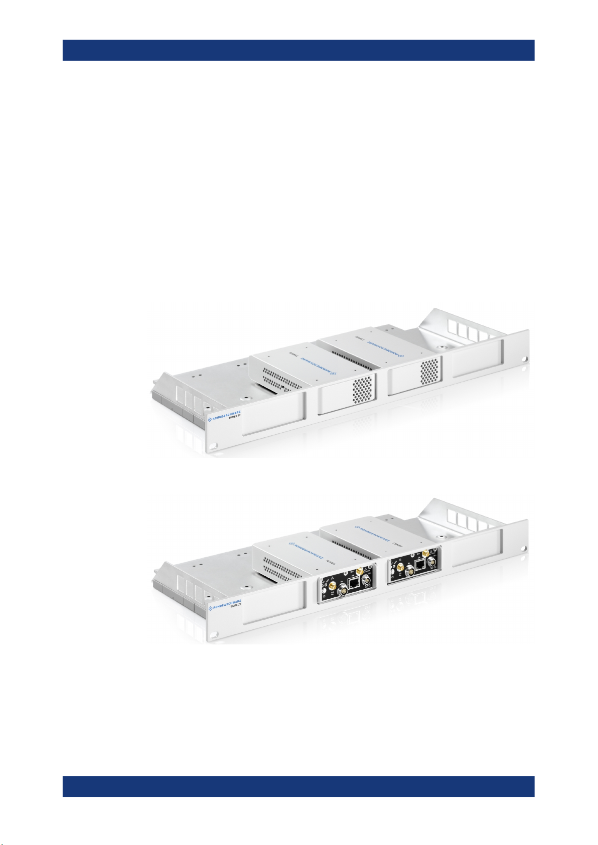
Rackmounting
The R&S TSME6 can be installed in a 19 inch rack using a rack adapter kit for one to
four R&S TSME6s (option R&S TSME6-Z2, R&S no. 4900.1030.02). The installation
instructions are part of the adapter kit.
Figure 3-1: Rackmounting of 2 R&S TSME6s
Figure 3-2: Rackmounting of 2 R&S TSME6s (reverse orientation of R&S TSME6s)
14User Manual 4900.0033.02 ─ 06

R&S®TSME6
Getting Started
Preparing for use
Figure 3-3: Rackmounting of 4 R&S TSME6s
Figure 3-4: Rackmounting of 4 R&S TSME6s (reverse orientation of R&S TSME6s)
3.1.3 Considerations for test setup
Electromagnetic interference (EMI) can affect the measurement results.
To suppress electromagnetic radiation during operation:
●
Use high-quality shielded cables, for example, double-shielded RF and LAN
cables.
●
Always terminate open cable ends.
●
Ensure that connected external devices comply with EMC regulations.
Signal input and output levels
Information on signal levels is provided in the data sheet. Keep the signal levels within
the specified ranges to avoid damage to the product and connected devices.
15User Manual 4900.0033.02 ─ 06

R&S®TSME6
3.1.4 Connecting to power
Getting Started
Preparing for use
Electromagnetic compatibility classes
The electromagnetic compatibility (EMC) class indicates where you can operate the
product. The EMC class of the product is given in the data sheet.
●
Class B equipment is suitable for use in:
– Residential environments
– Environments that are directly connected to a low-voltage supply network that
supplies residential buildings
●
Class A equipment is intended for use in industrial environments. It can cause
radio disturbances in residential environments due to possible conducted and radiated disturbances. It is therefore not suitable for class B environments.
If class A equipment causes radio disturbances, take appropriate measures to
eliminate them.
This section describes how to connect the R&S TSME6 to a power supply unit.
3.1.4.1 Connecting to a vehicle DC power supply via cigarette lighter
The R&S TSME6 is delivered with a 12 V DC power supply cable with a cigarette
lighter connector.
1. Check the rating of the vehicle DC power supply. It has to be 12 V.
2. Connect the 4-pin connector to DC IN.
3. Connect the cigarette lighter adapter to the 12 V outlet of the vehicle.
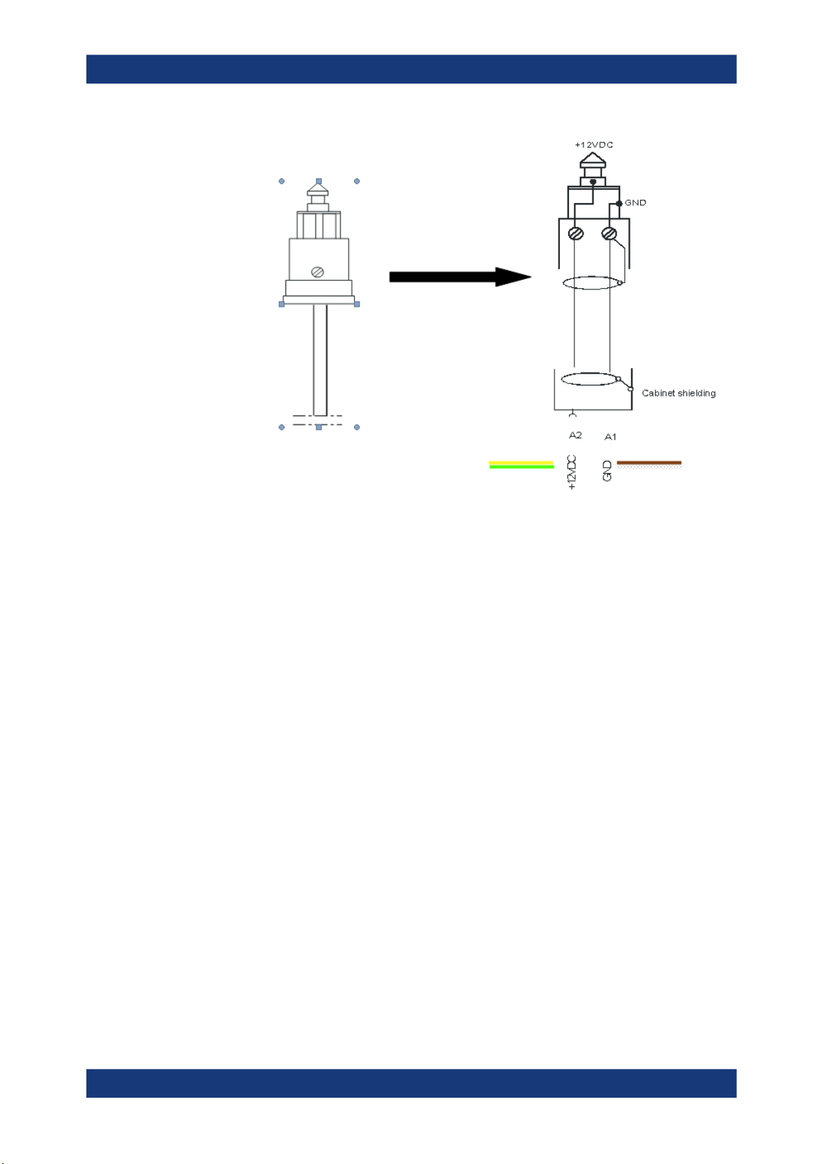
3.1.4.2 Connecting to the vehicle power supply via terminal
To connect vehicle power supply via terminal
1. Demount the cigarette lighter adapter from the cable.
2. Connect the open ends of the cable to the DC supply.
Ensure that the polarity is correct. (see Figure 3-5).
16User Manual 4900.0033.02 ─ 06
R&S®TSME6
Getting Started
Preparing for use
Figure 3-5: Supplied power cable with cigarette lighter adapter
+12 V DC = green/yellow cabling
GND = brown/white cabling
3.1.4.3 Connecting to an AC power supply
If you operate the product with an external power supply, you can use it indoors only in
pollution degree 2 environments where nonconductive contamination can occur. Suitable AC power supplies are listed in the data sheet. They differ in the output power:
●
R&S TSME-Z1 has an output power of about 30 W, sufficient for up to two products, one TSME6 and one TSME30/44DC.
●
R&S TSMA6-Z1 has an output power of 105 W and is suitable for multiple TSMx
products.
1. Ensure that the required ratings listed in the data sheet are matched.
2. Connect the round connector to DC IN.
3. Insert the AC power plug into a power outlet with ground contact.
3.1.5 Putting into operation
This section describes the basic steps to be taken when setting up the R&S TSME6 for
the first time.
17User Manual 4900.0033.02 ─ 06

R&S®TSME6
3.1.5.1 Setting up the LAN connection to the host PC
Getting Started
Preparing for use
EMI Suppression
Electromagnetic interference (EMI) may affect the measurement results.
To suppress generated electromagnetic interference (EMI):
●
Use only double shielded cables for RF and GPS connection when not using the
standard accessory.
●
Always terminate open cable ends.
●
DC-based lab networks are not allowed to be used for power supply.
●
LAN cable length to the next PC or switch must be < 30m.
●
Note the EMC classification in the data sheet.
To control and run measurements with the R&S TSME6, a host PC or notebook with
LAN interface is required.
The R&S TSME6 is equipped with a network interface and can be connected to an
Ethernet LAN (local area network). The interface can be used to connect the R&S
TSME6 to a host PC.
The following scenarios are possible.
●
Connection between PC and R&S TSME6(s) using static IP addresses.
●
Connection between PC and R&S TSME6(s) using dynamical generated IP
addresses (Auto-IP).
Operating Modes
●
"Full auto-IP" operating mode
IP addresses are automatically generated on PC and R&S TSME6(s) if the following conditions are met:
– PC network interface is configured to obtain an IP address automatically
– IP address stored in R&S TSME6(s) is not in range 169.254.0.1 –
169.254.255.254 (inclusive).
Note: This is the IP address set by the R&S TSME Device Manager.
●
"Partial auto-IP" operating mode
IP address is automatically generated on PC and a static IP address is used on
R&S TSME6 if the following conditions are met:
– PC network interface is configured to obtain an IP address automatically
– IP address stored in R&S TSME6 is in range 169.254.0.1 – 169.254.255.254
(inclusive).
Note: This is the IP address set by the R&S TSME Device Manager.
●
"Static IP" operating mode
IP address is manually set on PC and a static IP used on R&S TSME6 if the following conditions are met:
– PC LAN interface is configured to use a user-defined IP address, not in range
169.254.0.1 – 169.254.255.254 (inclusive).
18User Manual 4900.0033.02 ─ 06

R&S®TSME6
Getting Started
Preparing for use
Recommendations/Limitations of Operating Modes
●
"Full auto-IP" operating mode
– Only 1 PC and 1 or more R&S TSME6 devices per LAN interface, either con-
nected directly or via a L2 switch. (This operating mode shall not be used when
more than 1 PC is physically connected to the same subnetwork, e.g. via the
switch.)
– PC’s LAN interface shall not receive an IP from a DHCP server. (The IP
address generated for PC shall be matching following pattern:
169.254.X.Y.)
– All R&S TSME6 devices on the same LAN interface shall be configured with
stored IP addresses not in the range 169.254.1.0 – 169.254.254.255 (inclusive)
to prevent conflicts.
Note: R&S TSME6 devices with stored IP addresses in ranges 169.254.0.1 –
169.254.0.255 (inclusive) or 169.254.255.0 – 169.254.255.254 (inclusive) are
effectively operating in "partial auto-IP" operating mode.
– Depending on software accessing the R&S TSME6 devices, it may be manda-
tory to configure the stored IP addresses in all R&S TSME6 devices to be
unique.
Example: R&S TSME Device Manager does not have this requirement, R&S
ROMES / R&S Nestor may have such requirements depending on the use
made internally of the stored IP address as unique identifier.
●
"Partial auto-IP" operating mode
This mode shall only be used for specific cases, "full auto-IP" or "static IP" operating modes shall be preferred.
– 1 or more PCs and 1 or more R&S TSME6 devices per LAN interface, either
connected directly or via a L2 switch
– Each of the PC’s LAN interface physically connected to the sub network shall
not receive an IP from a DHCP server. (The IP address generated for PC shall
be matching following pattern: 169.254.X.Y.)
– All R&S TSME6 devices on the same LAN interface shall be configured with
stored IP addresses in the ranges 169.254.0.1 – 169.254.0.255 (inclusive) or
169.254.255.0 – 169.254.255.254 (inclusive), and use unique IP addresses.
These ranges are important to prevent conflicts with IP addresses dynamically
generated for the PC LAN interfaces.
Note: If a R&S TSME6 is shared with 2 or more PCs, and its stored IP address
is not in the defined range above, this may lead in rare cases to IP conflicts. It
is therefore recommended to respect this rule.
●
"Static IP" operating mode
– 1 or more PCs and 1 or more R&S TSME6(s), either connected directly or via a
L2 switch.
– Other network devices are permitted, as long as all IP addresses used are
unique.
This section describes how to configure the LAN interface for a single R&S TSME6. It
includes the following topics:
19User Manual 4900.0033.02 ─ 06
R&S®TSME6
Getting Started
Preparing for use
● Configuring the LAN interface on the host PC........................................................ 20
● Firewall configuration.............................................................................................. 22
● Connecting the R&S TSME6 to the host PC...........................................................23
Configuring the LAN interface on the host PC
Each R&S TSME6 has the default IP address 192.168.0.2. It is recommended that you
define the fixed IP address 192.168.0.1 to the host PC or configure the host PC to
obtain an IP address automatically ("Auto-IP").
To control the R&S TSME6 from the host PC, the LAN interface of the host PC must be
configured as follows:
1. Press the "Windows" key or the [CTRL + ESC] key combination on your keyboard
to access the Windows "Start" menu.
2. Type "Control Panel" and select this application.
3. Select "Control Panel > Network and Internet > Network and Sharing Center".
4. Select "Change adapter settings".
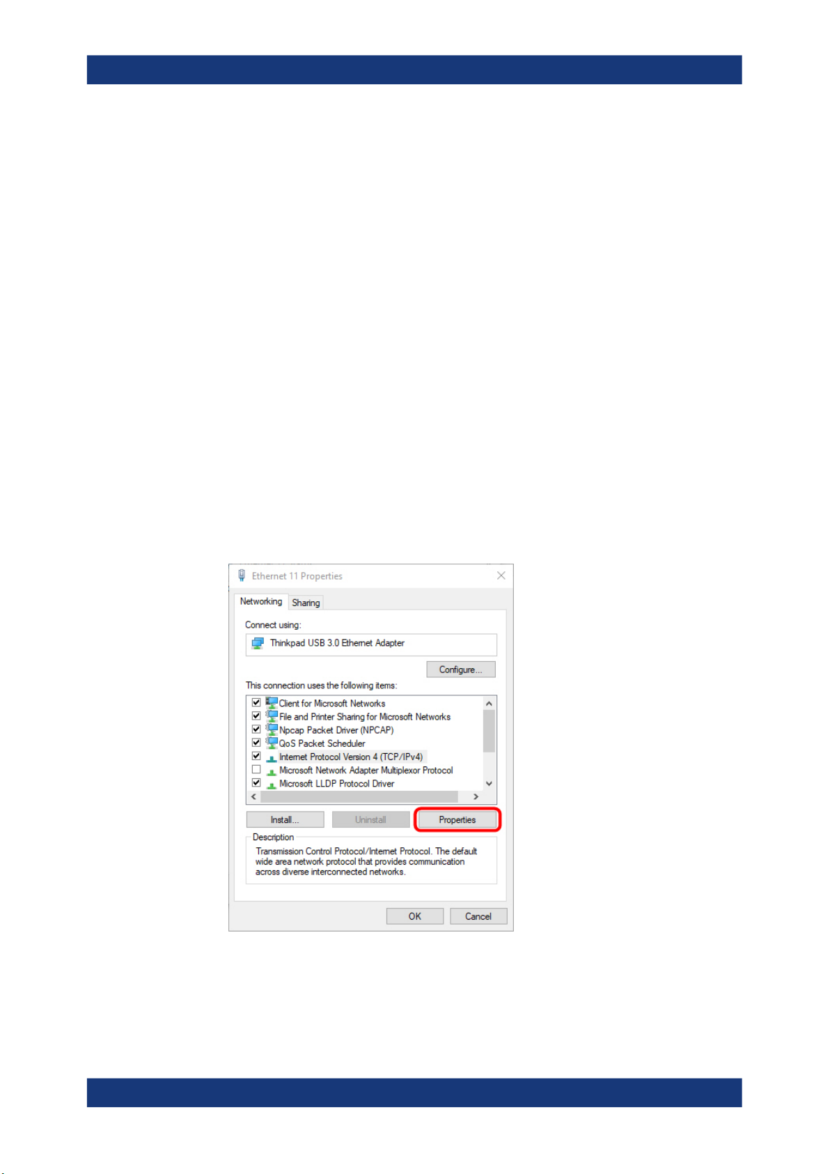
5. Double-click the LAN interface with which the R&S TSME6 is connected.
The items used by the LAN connection are displayed.
6. Select the entry named "Internet Protocol Version 4 (TCP/IPv4)".
7. Select the "Properties" button.
8. Configure the following TCP/IP settings:
20User Manual 4900.0033.02 ─ 06

R&S®TSME6
Getting Started
Preparing for use
a) Use any "Auto-IP" operating mode.
Select "Obtain an IP address automatically".
b) Use "Static IP" operating mode.
● Select "Use the following IP address" (fixed IP, no dynamic range)
● IP address: 192.168.0.1 (recommended)
● Subnet mask: 255.255.255.0
● No Default Gateway
9. Enable the use of 9-kB-jumbo frames:
a) Return to the "Local Area Connection Properties" dialog box.
b) Select the entry for the LAN adapter and then "Properties".
21User Manual 4900.0033.02 ─ 06

R&S®TSME6
Getting Started
Preparing for use
c) Switch to the "Advanced" tab.
d) Select the "Jumbo Frames" property and the "Value":"9014 Bytes".
Note: This setting may cause problems in Windows, but it is an important prerequisite for correct operation of the R&S TSME6.
See "Does the host provide a Gbit LAN connector and support 9k jumbo
frames?" on page 64.
10. Close the control panel, reboot the host PC and check if the connection can be
established successfully (see Chapter 7.1, "Guide to solve instrument connection
problems", on page 62).
If your firewall is active, make sure that it is configured as described in "Firewall config-
uration" on page 22.
Firewall configuration
The firewall can be turned off on the LAN interface or on with all the mandatory configurations.
If your firewall is active, make sure that your program is allowed to communicate
through the firewall. Following ports should be available:
●
RxPort (TSME6->PC): Port 17476
●
TxPort (PC->TSME6): Port 5140 and 16962
Also, the following parameters must be configured to decide if a specific program is
allowed to pass the firewall.
●
Multicast IP address for TSME: 224.17.4.76
●
Multicast Address for TSME6: 239.192.1.7
●
IP-Address of TSME6 has to be allowed as well: 192.168.0.2 (example)
Note: In "full auto-IP" operating mode, the IP address generated for the R&S
TSME6 has to be allowed.
●
Allow UDP Protocol
22User Manual 4900.0033.02 ─ 06

R&S®TSME6
Getting Started
Preparing for use
●
Allow Multicast Protocol
●
Allow executed application (ROMES, NESTOR, TsmeDeviceManager for examples)
●
Allow Network-Interface TSME(s) are connected to
●
Allow Network-Profile active on Network-IF TSME is connected to
Even if all these parameters are set properly, this rule can be overwritten in Windows
Firewall by a blocking rule. Furthermore on first execution of a program, windows ask
the user to decide on which network profiles communication through the firewall shall
be allowed. If it is set correct by user, the firewall is in a good state.
Connecting the R&S TSME6 to the host PC
The R&S TSME6 has a built-in 1000BASE-T (802.3ab), 1 Gbit/s Ethernet interface.
The host PC must have a separate 1 Gbit network interface card with an independent
LAN connection.
Dedicated LAN adapter and IP address for host PC
It is important for the host PC to have its own dedicated LAN adapter for the connection to one or more R&S TSME6s (or a switch), rather than being integrated in a regular office network.
If multiple R&S TSME6s are connected to one host PC, following rules are valid.
●
Using "static IP" or "partial auto-IP" operating mode, it is important to define unique
IP addresses for each instrument using the R&S TSME Device Manager (see R&S
TSME6 User Manual, chapter Configuring the R&S TSME6).
●
Using "full auto-IP" operating mode, it is recommended to define unique IP
addresses for each instrument, but depending on software run, it may not be mandatory.
► Connect the supplied LAN cable to the LAN connector on the rear panel of the
R&S TSME6, and to the host PC.
Windows 10 automatically detects the network connection and all devices in the
same subnet when the R&S TSME6 is switched on.
3.1.5.2 Connecting external devices
The SMA connector is sensitive to mechanical stress. Use the following handling precautions.
●
Always use a torque wrench and mount the cable end with 60 Ncm.
●
Do not stack adapters directly at the SMA connector. If you need to use adapters
(e.g: SMA to N), then always use a specific adapter cable (order no.
4900.1700.00).
23User Manual 4900.0033.02 ─ 06
R&S®TSME6
Getting Started
Preparing for use
The following external devices are required for standard operation.
●
Connect the instrument to the power supply as described in Chapter 3.1.4, "Con-
necting to power", on page 16.
●
Connect the PC or notebook LAN port to the LAN port of the R&S TSME6 as
described in Chapter 3.1.5.1, "Setting up the LAN connection to the host PC",
on page 18.
●
Connect the (optional) antenna's SMA-connector to the RF IN connector.
NOTE: Do not overload the input power at the RF input connector, otherwise the
input stage could be severely damaged. For maximum allowed values, see the
data sheet.
●
Connect the GPS antenna to the GPS ANT connector of the instrument for time
synchronization to a GPS signal (3 V, max. 25 mA for active antenna). To ensure
time synchronization of the R&S TSME6, it is required to have a GPS antenna connected.
NOTE: A missing GPS antenna will lead over time to the point that signals cannot
be detected anymore. We recommend to connect a GPS antenna at least once per
month.
●
Connect the R&S TSME30DC / R&S TSME44DC according to the measurement
setup description in R&S TSME30DC / R&S TSME44DC Ultracompact Downconverters manual.
Do not overload the input power at the RF input connector, otherwise the input stage
could be severely damaged. For maximum allowed values, see the data sheet.
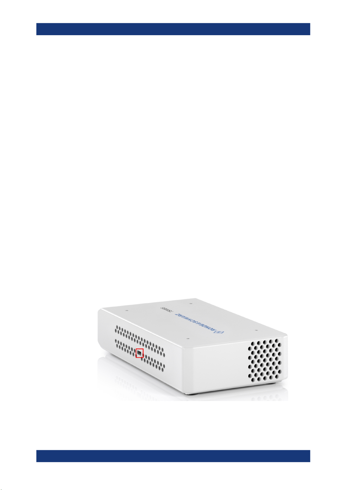
3.1.5.3 Connecting a kensington lock
The R&S TSME6 provides a connector for a Kensington lock, which can be used to
secure a mobile device against theft. The connector is on the side panel of the instrument.
Figure 3-6: Connector for a Kensington lock on theR&S TSME6
24User Manual 4900.0033.02 ─ 06
 Loading...