

Rohde&Schwarz R&S®TS7124M User Manual

R&S®TS7124M
RF Shielded Box
User Manual
(?IÃì2)
1525539402
User Manual
Version 04

This user manual describes the following R&S®TS7124M models and options:
●
R&S®TS7124M (1525.8564.02) RF Shielded Box without Front Feedthrough Ports
●
R&S®TS7124M (1525.8564.12) RF Shielded Box with two Front Feedthrough Ports
●
R&S®TS-F24ABS (1525.8593.02) Basic Absorber
●
R&S®TS-F24P1 (1525.8664.02 / .04) DUT Holder Tray with Raster
●
R&S®TS-F24-AH1 (1525.8887.02) Half Antenna Ring
●
R&S®TS-F24-AH3 (1530.5999.02 / .04) Half Antenna Ring with three Vivaldi Antennas
●
R&S®TS-F24-AR (1525.8906.02) Full Antenna Ring
●
R&S®TS-F24-AR3 (1530.6008.02 / .04) Full Antenna Ring with three Vivaldi Antennas
●
R&S®TS-F24-AH2 (1525.8893.02 / .12 / .22) Antenna Holder
●
R&S®TS-F24FN1 (1525.8870.02) Twin N-SMA Feedthrough
●
R&S®TS-F24FS1 (1530.1058.02) 4x SMA-SMA Feedthrough
●
R&S®TS-F24FK2 (1530.6372.02/.04) 2x / 4x PC 2.92 mm Feedthrough
●
R&S®TS-F24FV1 (1532.0836.02) 2x PC 1.85 mm Feedthrough
●
R&S®TS-F24FD1 (1525.8835.02) D-Sub Feedthrough (25 pin + 9 pin)
●
R&S®TS-F24FU1 (1525.8735.02) USB 2.0 Feedthrough
●
R&S®TS-F24FET (1525.8729.02) Gigabit Ethernet (LAN) Feedthrough
●
R&S®TS-F24FP1 (1525.8864.02) 4x FSMA Fiberoptic Feedthrough
●
R&S®TS-F24FF1 (1525.8858.02) 4x Pneumatic Feedthrough
●
R&S®TS-F24FAC1 (1526.4840.02) Power Feedthrough
●
R&S®TS-F24-V1 (1525.8964.02) Vivaldi Antenna V1 (0.7 - 14 GHz)
●
R&S®TS-F24-V2 (1525.8970.02) Vivaldi Antenna V2 (2.4 - 16 GHz)
●
R&S®TS-F24-V3 (1525.8987.02) Cross-Polarized Vivaldi Antenna V3 (1.7 - 20 GHz)
●
R&S®TS-F24NB2 (1525.8793.02) Narrowband Antenna (0.7 - 0.96 GHz)
●
R&S®TS-F24WA1 (1525.8670.02) Wideband Antenna (0.3 - 6 GHz)
●
R&S®TS-F2X-VH4 (1525.8758.02) 45° Adapter for Lateral Antenna Tilt
●
R&S®TS-F24HML1 (1530.8430.02) 3D Magnetic Helmholtz Coil (20 kHz - 1 MHz)
●
R&S®TS-F24HLF1 (1530.8446.02) Low Frequency Loop Antenna (20 kHz - 1 MHz)
●
R&S®TS-F24-Z1 (1526.6942.02) 19'' Rack Mounting Kit
© 2018 Rohde & Schwarz GmbH & Co. KG
Mühldorfstr. 15, 81671 München, Germany
Phone: +49 89 41 29 - 0
Fax: +49 89 41 29 12 164
Email: info@rohde-schwarz.com
Internet: www.rohde-schwarz.com
Subject to change – Data without tolerance limits is not binding.
R&S® is a registered trademark of Rohde & Schwarz GmbH & Co. KG.
Trade names are trademarks of the owners.
1525.5394.02 | Version 04 | R&S®TS7124M
Throughout this manual, products from Rohde & Schwarz are indicated without the ® symbol , e.g. R&S®TS7124M is indicated as
R&S TS7124M.

R&S®TS7124M
1 Preface.................................................................................................... 7
1.1 Key Features..................................................................................................................7
1.2 Documentation Overview............................................................................................. 8
2 Specific Safety Instructions..................................................................9
2.1 Explanation of Symbols............................................................................................. 10
2.2 Intended Use................................................................................................................11
2.3 Authorized Operators................................................................................................. 11
2.4 Safety Instructions for Unpacking, Transport and Mounting..................................11
2.5 Safety Instructions for Operation.............................................................................. 13
2.6 Safety Instructions for Maintenance......................................................................... 15
Contents
Contents
3 System Overview and Usage.............................................................. 16
4 Hardware Description..........................................................................17
4.1 Hardware Overview.....................................................................................................17
4.1.1 Front Tour......................................................................................................................17
4.1.2 Rear Tour...................................................................................................................... 20
5 Accessories..........................................................................................23
5.1 Basic Absorber R&S TS-F24ABS.............................................................................. 23
5.2 DUT Holder Tray R&S TS-F24P1................................................................................25
5.3 Half Antenna Ring R&S TS-F24-AH1......................................................................... 26
5.4 Half Antenna Ring with Three Vivaldi Antennas R&S TS-F24-AH3........................ 31
5.5 Full Antenna Ring R&S TS-F24-AR............................................................................32
5.6 Full Antenna Ring with Three Vivaldi Antennas R&S TS-F24-AR3.........................35
5.7 Antenna Holder R&S TS-F24-AH2............................................................................. 36
5.8 Twin N-SMA Feedthrough R&S TS-F24FN1.............................................................. 37
5.9 Four Times SMA-SMA Feedthrough R&S TS-F24FS1..............................................38
5.10 PC 2.92 mm Feedthrough R&S TS-F24FK2.............................................................. 39
5.11 Twin PC 1.85 mm Feedthrough R&S TS-F24FV1......................................................40
5.12 D-Sub Feedthrough R&S TS-F24FD1........................................................................ 40
5.13 USB 2.0 Feedthrough R&S TS-F24FU1..................................................................... 42
5.14 Ethernet (LAN) Feedthrough R&S TS-F24FET..........................................................42
3User Manual 1525.5394.02 ─ 04

R&S®TS7124M
5.15 Fiber-optic Feedthrough R&S TS-F24FP1................................................................ 43
5.16 Pneumatic Feedthrough R&S TS-F24FF1................................................................. 44
5.17 Power Feedthrough R&S TS-F24FAC1......................................................................45
5.18 Vivaldi Antenna R&S TS-F24-V1................................................................................ 47
5.19 Vivaldi Antenna R&S TS-F24-V2................................................................................ 49
5.20 Cross-Polarized Vivaldi Antenna R&S TS-F24-V3....................................................50
5.21 Narrowband Antenna R&S TS-F24NB2..................................................................... 52
5.22 Wideband Antenna R&S TS-F24WA1........................................................................ 55
5.23 45° Adapter for Lateral Antenna Tilt R&S TS-F2X-VH4............................................56
5.24 Magnetic Coil R&S TS-F24HML1............................................................................... 57
5.25 LF Loop Antenna R&S TS-F24HLF1.......................................................................... 63
5.26 Rack Mounting Kit R&S TS-F24-Z1............................................................................64
Contents
6 Putting into Operation......................................................................... 68
6.1 Setup............................................................................................................................ 68
6.1.1 ESD Requirements....................................................................................................... 69
6.1.2 Unpacking and Checking.............................................................................................. 69
6.1.3 Positioning the Chamber...............................................................................................70
6.1.4 Grounding the RF Shielded Box................................................................................... 71
6.1.5 RF Interfaces.................................................................................................................72
6.1.6 Mounting a Feedthrough............................................................................................... 72
6.1.7 Mounting a DUT Holder Tray........................................................................................ 73
7 Configuration........................................................................................77
7.1 Opening and Closing the Top Cover......................................................................... 78
7.1.1 Opening the Top Cover................................................................................................. 79
7.1.2 Closing the Top Cover...................................................................................................80
7.1.3 Adjusting the Locking Force of the Cover..................................................................... 83
7.2 Installation of an Antenna Ring or Holder................................................................ 85
7.2.1 Taking the Half Antenna Ring out of the Chamber........................................................86
7.2.2 Mounting the Half Antenna Ring into the Chamber.......................................................90
7.2.3 Taking the Full Antenna Ring out of the Chamber........................................................ 97
7.2.4 Mounting the Full Antenna Ring into the Chamber..................................................... 102
7.2.5 Taking the Antenna Holder out of the Chamber...........................................................111
4User Manual 1525.5394.02 ─ 04

R&S®TS7124M
7.2.6 Mounting the Antenna Holder into the Chamber......................................................... 113
7.3 Configuration of Vivaldi Antennas...........................................................................118
7.3.1 Definition of Rail and Antenna Positions on an Antenna Ring.................................... 120
7.3.2 Definition of Antenna Positions on the Antenna Holder.............................................. 126
7.4 Installation of Narrowband Antennas..................................................................... 128
7.4.1 Mounting Narrowband Antennas Into the Chamber....................................................129
7.4.2 Taking Narrowband Antennas Out of the Chamber.................................................... 138
7.5 Installation of the Wideband Antenna.....................................................................141
7.5.1 Mounting the Wideband Antenna Into the Chamber................................................... 141
7.5.2 Taking the Wideband Antenna Out of the Chamber....................................................145
7.6 Installation of the LF Loop Antenna........................................................................147
7.6.1 Mounting the LF Loop Antenna Into the Chamber...................................................... 148
7.6.2 Taking the LF Loop Antenna Out of the Chamber.......................................................151
Contents
8 Maintenance....................................................................................... 153
8.1 Safety Instructions for Maintenance....................................................................... 153
8.2 Compliant Maintenance............................................................................................153
8.3 Maintenance Intervals...............................................................................................153
8.4 Checking.................................................................................................................... 154
8.5 Cleaning..................................................................................................................... 156
8.5.1 Cleaning the Chamber................................................................................................ 156
8.5.2 Cleaning the Gasket Contact Area..............................................................................157
8.6 Storage.......................................................................................................................157
Glossary: List of Frequently Used Terms and Abbreviations........158
Index....................................................................................................160
5User Manual 1525.5394.02 ─ 04

R&S®TS7124M
Contents
6User Manual 1525.5394.02 ─ 04

R&S®TS7124M
1 Preface
1.1 Key Features
Preface
Key Features
The high-performance RF Shielded Box R&S TS7124M was developed to meet
demanding measurement requirements in radiated and conducted RF testing.
Figure 1-1: RF Shielded Box with front door / drawer opened
The use of a RF Shielded Box is a prerequisite for reliable and reproducible RF interface performance tests. It ensures that Devices under Test (DUTs) are not affected by
interference from external test systems that would distort the measurement results.
The shielding also prevents other external instruments or test systems from being
affected by the radiation tests.
To meet these requirements, the RF Shielded Box R&S TS7124M features:
●
A wide frequency range from 300 MHz to 6 GHz
●
A rugged mechanical design for reproducible results and long lifetime
●
A good antenna coupling factor
●
High shielding efficiency
●
Low reflection due to use of absorbent material
●
Multiple integrated and exchangeable RF connectors and filtered feedthroughs
●
A customer-configurable DUT holder and measurement tray
●
Flexible configurations of antenna ring and antennas
7User Manual 1525.5394.02 ─ 04

R&S®TS7124M
1.2 Documentation Overview
Preface
Documentation Overview
●
Extended modularity
The RF Shielded Box is exclusively intended for the use as a measurement equipment
in RF interface performance tests. It is intended to be used in conjunction with RF
measurement instruments and an RF test system. You must not use the RF Shielded
Box for any other purposes.
Risk of injury
Operation and handling of an RF Shielded Box implies risks.
To reduce these risks and prevent accidents, carefully read the user manual.
Especially read Chapter 2, "Specific Safety Instructions", on page 9.
The technical documentation for the RF Shielded Box consists of the following parts:
●
This user manual including important Specific Safety Instructions (printed or in
electronic format)
●
General safety instructions (separate, printed or in electronic format)
●
A CD-ROM that contains user manual, certificates, product brochure & data sheet
The entire user manual must be carefully read, understood and observed by:
●
Operators, tasked with working on the RF Shielded Box, prior to operating it for the
first time
●
Service engineers, prior to performing any maintenance or service tasks
Observing the user manual ensures the following:
●
Prevent hazards during transport, positioning and assembly
●
Prevent hazards during operation
●
Prevent hazards during configuration, maintenance and repair
●
Increase operation efficiency
●
Avoid downtime
●
Increase the reliability and lifetime of the RF Shielded Box
The operating instructions must always be available in the location where the RF Shielded Box is used. The operating organization is to supplement the operating instructions, as appropriate, with information on national health, safety and environmental
regulations.
8User Manual 1525.5394.02 ─ 04

R&S®TS7124M
2 Specific Safety Instructions
Specific Safety Instructions
Risk of injury
Setup and operation of an RF Shielded Box implies risks.
To reduce these risks and prevent accidents, carefully read the following chapter and
the rest of the user manual as well as the general safety instructions.
The RF Shielded Box has been manufactured in accordance with accepted engineering practices and the latest scientific and technical findings. Nevertheless, any RF
Shielded Box generates risks that cannot be prevented by design. To provide sufficient
safety for personnel using the RF Shielded Box, additional safety instructions have
been defined. A satisfactory level of safety while using the RF Shielded Box is assured
only if these instructions are observed.
For handling and operating the RF Shielded Box, some in-depth knowledge and skills
are required.
Personnel assigned to work with the RF Shielded Box must first read and understand
the entire user manual, particularly this chapter, before starting to work.
Operators must be trained and instructed on safety aspects and have to comply with:
●
National law and local regulations on health, safety, and environmental protection
●
Applicable standard procedures for health and safety
●
Technical standards, rules and instructions for the safe operation of test systems
●
Specific organizational obligations (e.g. regarding supervision, reporting, the organization of work, schedules, human resources, etc.)
The operating organization must, by means of internal precautions, ensure the following:
●
Only authorized persons are allowed to work on the RF Shielded Box, see Chap-
ter 2.3, "Authorized Operators", on page 11.
●
During operation of the RF Shielded Box, all safety regulations and operating
instructions must be adhered to strictly.
●
It is not permitted to make any changes, modifications or additions to the RF Shielded Box that could affect safety.
● Explanation of Symbols...........................................................................................10
● Intended Use........................................................................................................... 11
● Authorized Operators.............................................................................................. 11
● Safety Instructions for Unpacking, Transport and Mounting....................................11
● Safety Instructions for Operation.............................................................................13
● Safety Instructions for Maintenance........................................................................15
9User Manual 1525.5394.02 ─ 04

R&S®TS7124M
2.1 Explanation of Symbols
Specific Safety Instructions
Explanation of Symbols
Labels with the following symbols point out areas of risk on the chamber. In addition,
sections in this chapter which describe a specific risk are marked with the associated
symbol in the margin. The symbols have the following meaning:
Symbol Explanation
WARNING!
Indicates the risk of personal injury
In order to prevent personal injury observe and follow safety
instructions.
WARNING!
Indicates the risk of contusion of hand and fingers
In order to prevent contusion of the hand and fingers follow the
safety instructions on how to operate the chamber.
WARNING!
Indicates the risk of toes / foot injury due to the heavy chamber and
its door.
In order to prevent toes or foot injury, follow the safety instructions
for transport, unpacking and operation.
CAUTION!
Indicates a weight for heavy units >34 kg
In order to prevent personal injury, follow the safety instructions for
transport, unpacking and operation.
NOTICE
Indicates the risk of ESD
In order to prevent electrostatic discharge effects, follow the instructions in Chapter 6.1.1, "ESD Requirements", on page 69. Electrostatic sensitive devices require special care.
NOTICE
Indicates a risk of damage to the installation
To prevent damage to the RF Shielded Box or incorrect measurement results, follow the safety instructions.
Earth (ground)
10User Manual 1525.5394.02 ─ 04

R&S®TS7124M
2.2 Intended Use
2.3 Authorized Operators
Specific Safety Instructions
Safety Instructions for Unpacking, Transport and Mounting
The RF Shielded Box is intended for radiation testing of electronic devices. Use the
device under test (DUT) only with the appropriate, specially manufactured cables and
adapters. Any other use is regarded as improper use, which can result in safety hazards and damage.
The RF Shielded Box is only permitted to be operated within the permissible parameter
ranges as specified in the data sheet.
The RF Shielded Box is intended for industrial use and must only be installed, operated, configured, maintained and repaired by appropriately trained personnel.
An authorized operator is a person who, as a result of special instruction or training
courses, is familiar with handling the RF Shielded Box. The operator must have read
and understood all operating instructions. Only trained personnel with the proper
instruction is permitted to carry out work on the RF Shielded Box.
The duties of personnel responsible for the following must be clearly defined:
●
Installation
●
Operation
●
Configuration
●
Maintenance
●
Repair
When instructing personnel, particular emphasis should be laid on possible hazards
and on the safety procedures. Proper use also includes the observance of this user
manual and the observance of the inspection and maintenance requirements (see
Chapter 8, "Maintenance", on page 153).
2.4 Safety Instructions for Unpacking, Transport and Mounting
Risk of contusion due to heavy moving parts
For transportation, the RF Shielded Box is originally contained in a special transport
protection packaging. After unpacking, there is no additional protection to prevent
opening of the drawer. Especially when the chamber is tilt, the drawer can slide open
unintentionally. This movement can cause personal injuries, especially contusion.
To avoid this risk, make sure that the RF Shielded Box is always in a horizontal position.
11User Manual 1525.5394.02 ─ 04

R&S®TS7124M
Specific Safety Instructions
Safety Instructions for Unpacking, Transport and Mounting
Figure 2-1: Tipping hazard with the drawer sliding open in an uncontrolled manner
An additional safety measure is implemented by a metal safety latch next to the top left
corner of the front door. This latch prevents unintentional opening of the drawer:
Figure 2-2: Metal safety latch
When you remove this safety latch and especially when the chamber is tilt, the drawer
can slide open unintentionally. This movement can cause personal injuries, especially
contusion.
To avoid this risk, leave the safety latch mounted until the chamber is securely mounted.
Never use the handle for lifting the RF Shielded Box.
Packaging material
To be prepared for later transportation or shipping of the RF Shielded Box, retain the
original special transport protection packaging and the safety latch (Figure 2-2). If the
RF Shielded Box has to be transported or shipped again, attach the safety latch and
repack the chamber in its original packaging, which keeps the drawer closed.
If the original packaging material and the metal safety latch are no longer available,
secure the drawer against unintentional opening in an appropriate way.
Risk of injury due to heavy weight
12User Manual 1525.5394.02 ─ 04

R&S®TS7124M
Specific Safety Instructions
Safety Instructions for Operation
Handling the heavy chamber (e.g. lifting or transporting it) may result in personal injury.
In order to prevent this, at least two persons are required for handling the RF Shielded
Box. Never use the handle for lifting the RF Shielded Box.
The RF Shielded Box must be mounted by fixing it horizontally to a stable bench/
support with screws and four brackets, see Chapter 6.1, "Setup", on page 68.
Risk of injury due to unstable mounting
The support (bench, table, rack, or the like) onto which the RF Shielded Box is to be
mounted, has to be sufficiently stable to bear the chamber's weight and to withstand
the door's momentum during operation. The screws with which the mounting brackets
(see Chapter 6.1.3, "Positioning the Chamber", on page 70) are fixed to the support,
have to be suitable to hold a tight grip in the support's material and strong enough to
withstand a dynamic long-term load. If the support or the screws should fail, the chamber may become destabilized and eventually tip out of place. This could cause personal injuries, especially contusion.
To avoid this risk, make sure that the RF Shielded Box is securely mounted on a stable
support.
2.5 Safety Instructions for Operation
Risk of injury due to door operation
The heavy RF Shielded Box features a solid metal door that can be manually opened
and closed. The heavy weight is required to achieve high levels of electromagnetic
shielding. If the door is closed without caution, this implies some risk of injury for the
operators.
13User Manual 1525.5394.02 ─ 04
R&S®TS7124M
Specific Safety Instructions
Safety Instructions for Operation
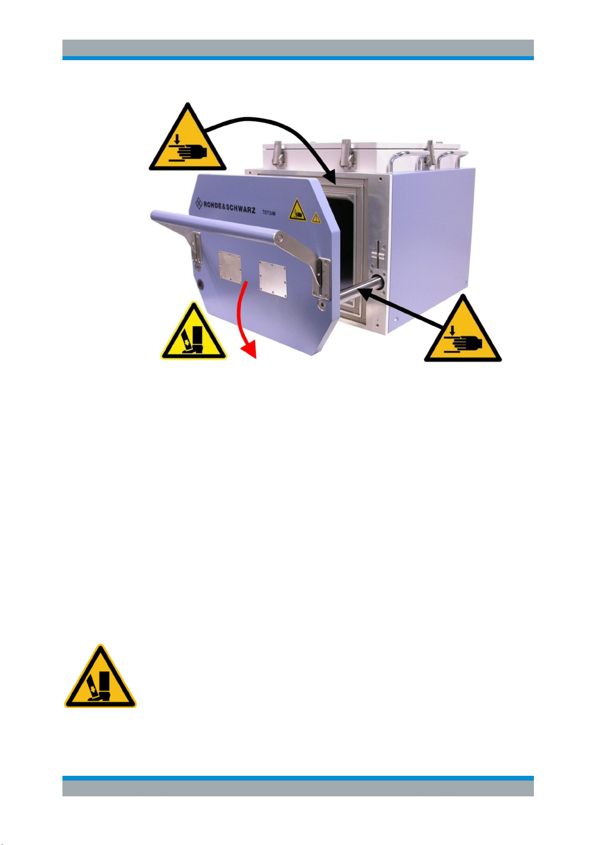
Figure 2-3: Mechanical hazards involved with the moving front door / drawer (left) as well as with the
guide rail. The red arrow indicates the risk of a tipping chamber if it is opened without
being fixed to a stable support
The inertia of the door, if it is closed fast, may be sufficient to cause personal injury,
especially contusion of hands and fingers. To avoid this risk of "fast" contusion, always
keep away from the gap between the chamber's door and wall, while closing the door.
Additionally, there is a risk of "slow" contusion between door and chamber, while locking the door by its handle. To reduce this risk, the locking mechanism is only engaged
if the door is almost closed: Once the locking hooks of the handle are caught in their
counterpart in the chamber wall, the gap between door and chamber is too small to
insert fingers.
However, any mechanism could fail. To avoid potential risks, keep away from the gap
between the door and the chamber, when the door is about to be closed. Also, do not
touch the movable guide rails.
Risk of contusion due to heavy moving parts
Both the chamber and the door are heavy. The weight and the leverage effect of the
open drawer is sufficient to destabilize the whole chamber and make it tilt forward. This
risk is enhanced by the typical situation of the opened door protruding over the edge of
a table or support.
The risk of tilting is especially high during the installation phase, before the RF Shielded Box is securely mounted in a horizontal position (see Figure 2-1). With neither the
special transport protection packaging nor the handle keeping the door closed, the
14User Manual 1525.5394.02 ─ 04

R&S®TS7124M
Specific Safety Instructions
Safety Instructions for Maintenance
combination of a tilting movement of the whole chamber and the drawer sliding open
unintentionally could enhance the risk.
Any of these instability conditions might lead to personal injury, especially contusion.
To avoid this risk, make sure that prior to operation the chamber is securely mounted to
a stable support (see Chapter 6.1, "Setup", on page 68).
Risk of injury in case of malfunction
If the RF Shielded Box is operated without being in proper working order, malfunctions
could lead to unpredictable events.
To avoid risks in the event of a malfunction,
●
immediately take the chamber out of operation,
●
report the malfunction to the responsible department,
●
eliminate any faults before work is continued.
Other Safety Instructions
Persons not trained in handling the RF Shielded Box must be kept out of the range of
operation, as they may not know about all potential hazards of injury.
Observe the site's internal instructions and ensure that the area of operation is always
clear and clean. All areas for operation and maintenance must be kept easy to access.
2.6 Safety Instructions for Maintenance
Risk of injury in case of uninformed maintenance
If maintenance tasks are performed by untrained personnel, this may lead to risks of
personal injury and damage to the equipment.
To avoid these risks, maintenance tasks may only be performed by trained personnel.
Risk of damaging mechanical parts
To avoid malfunction and damage to mechanical parts,especially the drawer guide rails
(3 in Figure 4-1), do not apply liquid cleaning agents such as contact spray.
15User Manual 1525.5394.02 ─ 04

R&S®TS7124M
3 System Overview and Usage
System Overview and Usage
The RF Shielded Box is an adaptation platform, built for the testing of electronic devices with RF interfaces, especially
●
Mobile phones
●
PDAs
●
Radio keys
●
WLAN / Wi-Fi modules
●
Bluetooth® modules, etc.
The R&S TS7124M is used in production, for service, repairs and other applications.
For radiation testing, the DUT is inserted into the chamber by means of a drawer,
which is closed by a tightly sealing door. Antennas installed on the inside of the RF
Shielded Box then interact with the DUT by emitting or receiving electromagnetic radiation. The antennas can be placed and oriented in a customer-specific geometrical
arrangement.
Submitting a DUT to conducted instead of radiated RF signals via feedthroughs for RF
cables (or guiding conducted RF signals away from the DUT) can be applied as an
alternative or supplement to antennas.
The susceptibility and behavior of the DUT can be monitored via USB or D-Sub feedthrough connections, which can also be used to send control commands to the DUT.
For this purpose, it is recommended to use version 1525.8564.12 of the RF Shielded
Box with two feedthrough ports in the front door.
To minimize redundancy in the manual, most of the descriptions refer to this RF Shielded Box version. However, the descriptions apply in a similar way to the basic version
1525.8564.02 that does not feature port openings for front feedthroughs.
Control signals and measured signals may typically be managed by a customer-specific test system. This could be designed to handle one individual RF Shielded Box, or
several, or even a large number of chambers. The test system may typically comprise:
●
Signal generators
●
RF cables
●
Signal switch boxes
●
Signal analyzers
●
Data recorders
●
A computer-based control system
●
Racks for mounting multiple RF Shielded Boxes
16User Manual 1525.5394.02 ─ 04

R&S®TS7124M
4 Hardware Description
4.1 Hardware Overview
4.1.1 Front Tour......................................................................................................................17
4.1.2 Rear Tour...................................................................................................................... 20
Hardware Description
Hardware Overview
This chapter describes all components of the RF Shielded Box. It also provides some
information on their use and function (for more, see Chapter 3, "System Overview and
Usage", on page 16).
For operation issues, see Chapter 6, "Putting into Operation", on page 68.
For configuration issues, see Chapter 7, "Configuration", on page 77.
For maintenance issues, see Chapter 8, "Maintenance", on page 153
4.1.2.1 Rear Feedthroughs....................................................................................................... 21
4.1.1 Front Tour
Figure 4-1: Front view of the opened RF Shielded Box
1 = Front door of the drawer (RF Shielded Box version 1525.8564.12), for DUT exchange
2 = Two grooves filled with elastic gasket for sealing the drawer's door
3 = Drawer guide rail
4 = The door's handle, here lifted up to the "open" position
17User Manual 1525.5394.02 ─ 04

R&S®TS7124M
Hardware Description
Hardware Overview
The front drawer (1) of the RF Shielded Box is used for insertion of the DUT. The
drawer guide rails (3, one on each side) support the drawer when it is manually opened
and closed by means of the handle (4).
The polymeric gasket (2) features a conductive chromated aluminum surface to prevent leakage of RF radiation out of the chamber, and into it. Avoid touching or soiling
the gasket. The front door's gasket is highly elastic for a long life over many opening
and closing cycles (see Chapter 8.3, "Maintenance Intervals", on page 153).
Figure 4-2: Rear view of the drawer door
5 = Profile grooves for sealing the door
6 = RF absorber foam
7 = Upper position inside the drawer door for mounting the DUT holder tray
8 = Two openings in the absorber foam for accessing the feedthroughs (only in RF Shielded Box version
1525.8564.12)
9 = Lower position inside the drawer door for mounting the DUT holder tray
Several profile grooves (5) in the door and an optional absorber plate (6) help to seal
the chamber against leakage of electromagnetic radiation.
On the inside of the drawer door of the RF Shielded Box, it is possible to fix various
optional DUT holder trays:
●
standard or custom-made
●
with or without raster for DUT positioning
●
directly mounted to the door or fixed with the help of an adapter
Such a tray is intended to hold the DUT during insertion into the chamber and during
the test.
18User Manual 1525.5394.02 ─ 04

R&S®TS7124M
Hardware Description
Hardware Overview
Figure 4-3: Front view of the closed RF Shielded Box
10 = Handles for lifting the RF Shielded Box
11 = Only in RF Shielded Box version 1525.8564.12: two openings in the front door for optional feed-
throughs (here covered with two metal plates)
12 = Two front screw holes for mounting brackets (included in shipment)
There are two handles (10) on each side of the RF Shielded Box. If the chamber is lifted or transported (prior to mounting), at least two persons are required for handling it.
Two screw holes (12) at the lower end (and two more at the rear side) serve for fixing
the chamber to a stable support by means of special brackets (see Chapter 6.1,
"Setup", on page 68).
Various filtered control feedthroughs and RF feedthroughs are available (see Chap-
ter 5, "Accessories", on page 23). They can be mounted in the front door after
removing one or both of the metal plates (11) that cover the openings. The interfaces in
the feedthroughs can be used for controlling and monitoring a DUT while it is tested
inside the closed chamber, or for feeding RF signals through the door to or from the
DUT. As the three openings on the rear side of the RF Shielded Box (see Figure 4-4)
are numbered 1 to 3, the numbering convention for the two openings on the front side
of the chamber is 4 to 5 from left to right.
In Figure 4-3, a few small threaded holes on the outside of the front door can be seen
on the lower left side. These are no through holes, the chamber's RF shielding is not
impaired. They are intended to screw on a fixture that guides cables from the front
feedthroughs to an optional energy chain.
19User Manual 1525.5394.02 ─ 04

R&S®TS7124M
4.1.2 Rear Tour
Hardware Description
Hardware Overview
Figure 4-4: Rear side view of the RF Shielded Box
13 = Top cover for configuration and service issues
14 = Warranty seal of the top cover
15 = Six quick clamps of the top cover
16 = Four Rear Feedthroughs for up to four antennas inside the chamber
17 = Three metal plates covering openings in the rear chamber wall for up to three optional feedthroughs,
specified in Chapter 5, "Accessories", on page 23
18 = Earth (ground) contact
19 = Two rear screw holes for mounting brackets (included in shipment)
The top cover (13) of the RF Shielded Box is fixed by six quick clamps (15). It can be
removed for antenna configuration and service issues (see Chapter 7.1, "Opening and
Closing the Top Cover", on page 78).
The warranty seal (14) indicates that the R&S TS7124M is in its original delivery state,
with a shielding effectiveness as specified in the data sheet. For configuration of the
interior of the RF Shielded Box, the top cover has to be opened and the seal has to be
broken. After closing the cover it is in the user's responsibility to restore a good shielding effectiveness. To do so, proceed as described in Chapter 7.1.3, "Adjusting the
Locking Force of the Cover", on page 83.
At the rear side of the RF Shielded Box, there are four shielded RF feedthrough connectors (16, see Chapter 4.1.2.1, "Rear Feedthroughs", on page 21). These can be
used, e.g., for up to four individual antennas (see Chapter 5, "Accessories",
on page 23), or for up to two antennas with dual polarization (see Chapter 5.20,
"Cross-Polarized Vivaldi Antenna R&S TS-F24-V3", on page 50).
20User Manual 1525.5394.02 ─ 04

R&S®TS7124M
4.1.2.1 Rear Feedthroughs
Hardware Description
Hardware Overview
Three metal cover plates (17) at the rear side of the chamber can optionally be
replaced by additional filtered control feedthroughs or RF feedthroughs (see Chapter 5,
"Accessories", on page 23). For example, with each Twin N-SMA Feedthrough
R&S TS-F24FN1 providing two additional RF feedthroughs (from SMA to N connector),
a total of ten individual antennas can be connected inside the RF Shielded Box. For
more details, see Chapter 4.1.2.1, "Rear Feedthroughs", on page 21.
Two screw holes (19) at the lower end (and two more at the front side) serve for fixing
the chamber to a stable support by means of special brackets (see Chapter 6.1,
"Setup", on page 68).
Figure 4-5: Four rear RF feedthroughs and three openings for additional optional feedthroughs
1 = Four N connectors for feeding RF signals through the chamber wall to the antennas
2 = Three metal cover plates for additional exchangeable feedthroughs, specified in Chapter 5, "Accesso-
ries", on page 23. The numbering convention for these openings is 1 to 3 from left to right, when seen
from the rear side.
The numbering convention of the RF feedthrough connectors (1) is anti-clockwise from
1 to 4, when seen from the rear side of the RF Shielded Box, as shown below:
21User Manual 1525.5394.02 ─ 04

R&S®TS7124M
Hardware Description
Hardware Overview
Figure 4-6: Numbering of the RF feedthrough connectors on the rear side of the chamber
When looking from the front into the shielded chamber, the numbering on the inside is
clockwise, as shown in the next figure:
Figure 4-7: Numbering of the RF feedthrough connectors as seen on the inside of the chamber
The three metal cover plates (labeled 2 in
Figure 4-5) can be removed to install addi-
tional optional filter or RF feedthrough connectors. These openings are numbered 1 to
3 from left to right, when seen from the rear side of the chamber.
Risk of reduced shielding efficiency
If the metal cover plates are replaced by feedthrough connectors, care must be taken
to restore the chamber’s shielding efficiency. For correct installation, see mounting
instructions for feedthrough connectors. If a feedthrough is installed incorrectly, the
shielding efficiency may deteriorate dramatically.
22User Manual 1525.5394.02 ─ 04

R&S®TS7124M
5 Accessories
Accessories
Basic Absorber R&S TS-F24ABS
The following accessories are available for the R&S TS7124M:
● Basic Absorber R&S TS-F24ABS........................................................................... 23
● DUT Holder Tray R&S TS-F24P1........................................................................... 25
● Half Antenna Ring R&S TS-F24-AH1..................................................................... 26
● Half Antenna Ring with Three Vivaldi Antennas R&S TS-F24-AH3........................31
● Full Antenna Ring R&S TS-F24-AR........................................................................32
● Full Antenna Ring with Three Vivaldi Antennas R&S TS-F24-AR3........................ 35
● Antenna Holder R&S TS-F24-AH2..........................................................................36
● Twin N-SMA Feedthrough R&S TS-F24FN1...........................................................37
● Four Times SMA-SMA Feedthrough R&S TS-F24FS1...........................................38
● PC 2.92 mm Feedthrough R&S TS-F24FK2...........................................................39
● Twin PC 1.85 mm Feedthrough R&S TS-F24FV1.................................................. 40
● D-Sub Feedthrough R&S TS-F24FD1.................................................................... 40
● USB 2.0 Feedthrough R&S TS-F24FU1................................................................. 42
● Ethernet (LAN) Feedthrough R&S TS-F24FET.......................................................42
● Fiber-optic Feedthrough R&S TS-F24FP1..............................................................43
● Pneumatic Feedthrough R&S TS-F24FF1..............................................................44
● Power Feedthrough R&S TS-F24FAC1..................................................................45
● Vivaldi Antenna R&S TS-F24-V1............................................................................ 47
● Vivaldi Antenna R&S TS-F24-V2............................................................................ 49
● Cross-Polarized Vivaldi Antenna R&S TS-F24-V3..................................................50
● Narrowband Antenna R&S TS-F24NB2..................................................................52
● Wideband Antenna R&S TS-F24WA1.................................................................... 55
● 45° Adapter for Lateral Antenna Tilt R&S TS-F2X-VH4..........................................56
● Magnetic Coil R&S TS-F24HML1........................................................................... 57
● LF Loop Antenna R&S TS-F24HLF1...................................................................... 63
● Rack Mounting Kit R&S TS-F24-Z1........................................................................ 64
5.1 Basic Absorber R&S TS-F24ABS
The R&S TS-F24ABS (1525.8593.02) is the basic absorber material placed on the
inside of all walls of the chamber, including the door, the top cover and the ground.
Optionally, the RF Shielded Box can be ordered without these absorbers, but for most
applications (and for this user manual) it is assumed that it would typically be installed
in the chamber.
23User Manual 1525.5394.02 ─ 04

R&S®TS7124M
Accessories
Basic Absorber R&S
Figure 5-1: Empty chamber with basic absorber material (seen from top, cover removed)
TS-F24ABS
The absorber type Eccosorb LS22 from Emerson and Cuming is used, featuring the
following properties:
Absorber material properties at 3 GHz at 10 GHz
Attenuation (dB/cm) 7.4 14.9
Relative Impedance (|Z|/Z0) 0.55 0.74
Depending on the accessories installed inside the RF Shielded Box, different configurations of absorber material are provided for the chamber's top cover:
Figure 5-2: Different absorber material configurations on the inside of the top cover. In these pic-
1 = Standard absorber for use with Narrowband Antenna R&S TS-F24NB2
2 = Absorber for use with Half Antenna Ring R&S TS-F24-AH1 or Full Antenna Ring R&S TS-F24-AR
3 = Absorber for use with Wideband Antenna R&S TS-F24WA1
tures, the "FRONT" edge of the cover is on the right-hand side
All three absorber material configurations are compatible with antennas mounted on
the Antenna Holder R&S TS-F24-AH2.
If the basic absorber material is damaged, it has to be replaced.
24User Manual 1525.5394.02 ─ 04

R&S®TS7124M
Accessories
5.2 DUT Holder Tray R&S TS-F24P1
The R&S TS-F24P1 (1525.8664.02 or 1525.8664.04) is an optional tray for holding a
DUT in a defined position. The maximum load on the tray is 1 kg.
Variant .02: DUT holder tray pre-mounted in the upper position of the chamber door,
see Figure 5-5.
Variant .04: DUT holder tray pre-mounted in the lower position.
DUT Holder Tray R&S
TS-F24P1
Figure 5-3: DUT holder tray (R&S TS-F24P1)
The DUT holder tray is mounted on the inside of the drawer door with two hexagon
socket screws. To loosen or tighten the screws, use a 5 mm hex key with ball end:
Figure 5-4: Mounting the DUT holder tray on the inside of the drawer door
The DUT holder tray is mounted either in a lower or a higher position on the inside of
the drawer door.
25User Manual 1525.5394.02 ─ 04

R&S®TS7124M
Accessories
Half Antenna Ring R&S
TS-F24-AH1
For an instruction on how to change that position, see Chapter 6.1.7, "Mounting a DUT
Holder Tray", on page 73.
Figure 5-5: DUT holder tray mounted at the drawer door
Top left = Variant 1525.8664.02, tray pre-mounted in the upper position
Lower left = Variant 1525.8664.04, tray pre-mounted in the lower position
Right = Tray with printed raster from A to U and from 1 to 21 for reproducible DUT positioning
If the full antenna ring is placed in the chamber, the DUT holder tray must not be
mounted in the lower position, to avoid a collision.
See "Risk of tray collision with the full antenna ring" on page 74
The DUT holder tray is not a serviceable part. If it is defective or not working correctly,
it has to be replaced.
5.3 Half Antenna Ring R&S TS-F24-AH1
The R&S TS-F24-AH1 (Rohde & Schwarz order number 1525.8887.02) is an optional
antenna mounting structure to be placed inside the RF Shielded Box, in the upper half
of it. Hence, this antenna ring is called "half antenna ring" to differentiate it from the Full
Antenna Ring R&S TS-F24-AR that fills the whole chamber.
It would be possible to place two half antenna rings inside the R&S TS7124M, but this
setup is not recommended, since it is not stable. If necessary, use the full antenna ring
instead.
26User Manual 1525.5394.02 ─ 04

R&S®TS7124M
Accessories
Half Antenna Ring R&S
TS-F24-AH1
The half antenna ring is compatible with the following antennas on their antenna fixtures:
●
Vivaldi Antenna R&S TS-F24-V1
●
Vivaldi Antenna R&S TS-F24-V2
●
Cross-Polarized Vivaldi Antenna R&S TS-F24-V3
●
Additionally, each Vivaldi antenna can be mounted on the 45° Adapter for Lateral
Antenna Tilt R&S TS-F2X-VH4, which is also compatible with the half antenna ring.
Figure 5-6: Half antenna ring with three rails (or antenna ring bars, or cross struts)
1 = Rail 1
2 = Rail 2
3 = Rail 3
4 = Stiffening rib (one on the left, one on the right-hand side)
5 = Half antenna ring plate (one in the front, one rear)
6 = Label "FRONT", indicating the front side of the half antenna ring
The rails (or bars, or cross struts) in the half antenna ring are numbered 1 - 2 - 3 from
left to right as shown in Figure 5-6, seen from the front of the RF Shielded Box.
Various antennas can be mounted to the rails by means of special antenna fixtures:
27User Manual 1525.5394.02 ─ 04

R&S®TS7124M
Accessories
Half Antenna Ring R&S
TS-F24-AH1
Figure 5-7: Half antenna ring with three Vivaldi antennas mounted on 45° adapters (here: not tilted)
Figure 5-8: Expanding rivet
a = Drive pin and expansion peg
b = The drive pin is inserted into the expansion peg
Expanding rivets as shown above serve for keeping the antenna ring components
together, as shown below, and also for mounting antennas onto their fixtures (see Fig-
ure 5-11).
28User Manual 1525.5394.02 ─ 04

R&S®TS7124M
Accessories
Half Antenna Ring R&S TS-F24-AH1
Figure 5-9: Mounting an antenna on the antenna ring bar (or rail)
a = Place the antenna fixture in the desired position and insert the expansion peg (through the rail)
b = Insert the drive pin into the expansion peg
c = Push the drive pin all the way into the expansion peg
For removing an expanding rivet, carefully push back the drive pin from the opposite
side. A small tool tip (flat screw driver) is helpful for this purpose. Alternatively, lift the
cap of the rivet's drive pin with a slim pointed tool.
Figure 5-10: Variable orientation of a Vivaldi antenna on the rails of the half antenna ring
a = Antenna in 0° axial rotation
b = Antenna in 45° axial rotation
c = Antenna in 90° axial rotation
The antenna fixture and antenna ring bar allow changing the rotational orientation of an
antenna in angular steps of 45° as in Figure 5-10.
Figure 5-11: Antenna fixture with expanding rivets
1 = Expanding rivets
2 = Antenna fixture
29User Manual 1525.5394.02 ─ 04

R&S®TS7124M
Accessories
Half Antenna Ring R&S TS-F24-AH1
Figure 5-12: One of the Vivaldi antennas and its fixture
Mounting procedure for Vivaldi antennas and their fixtures
To mount a Vivaldi antenna onto its fixture, proceed as follows:
1. Place the antenna on the fixture, with holes aligned, oriented as in Figure 5-12
(SMP connector on the right).
2. Insert four expansion pegs into the holes.
3. While keeping the antenna and fixture in close contact, insert the drive pins into the
expansion pegs.
4. Push the drive pins all the way into the expansion pegs.
Figure 5-13: Vivaldi antenna with antenna fixture and SMP connection
30User Manual 1525.5394.02 ─ 04
 Loading...