

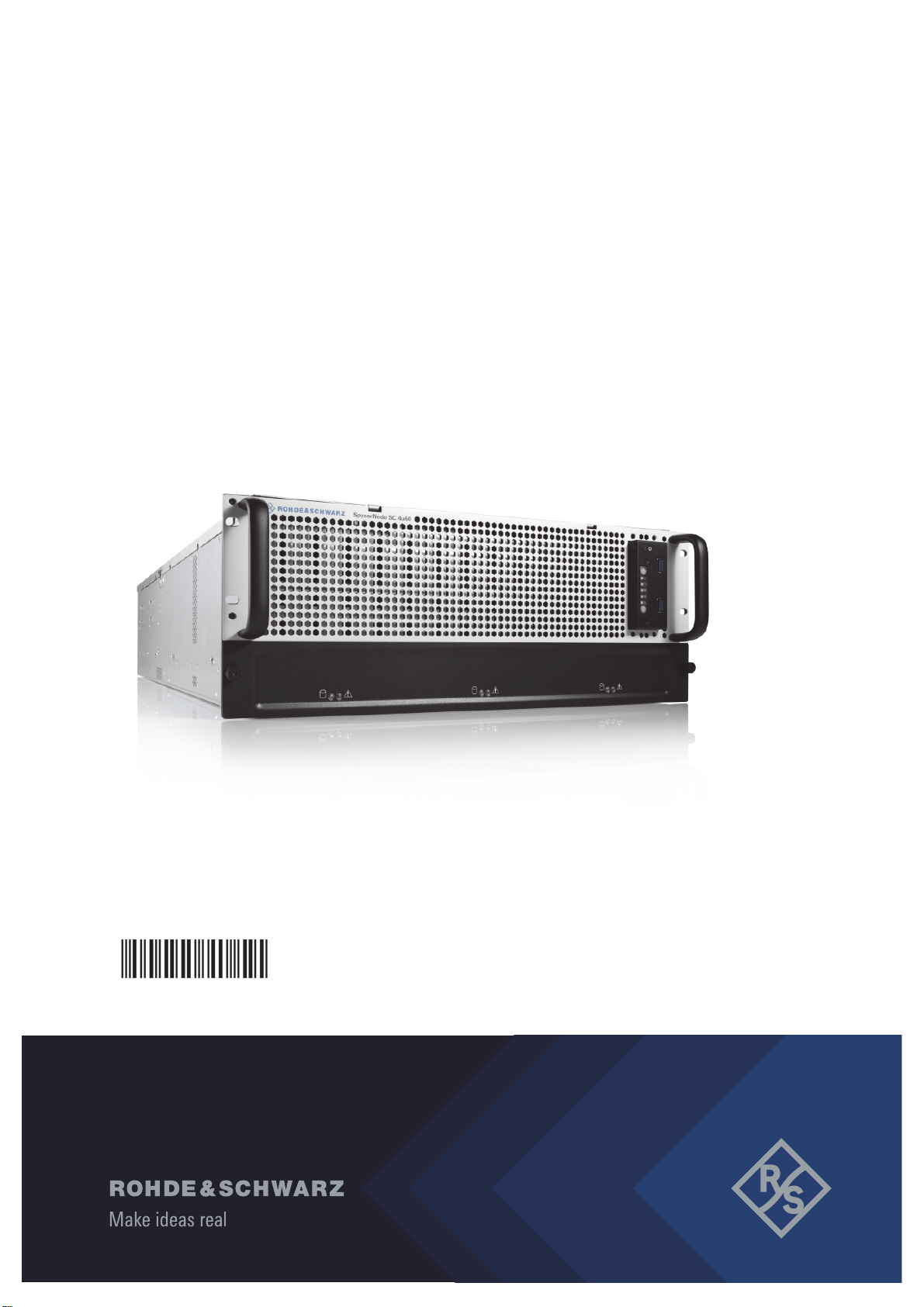
R&S®SpycerNode SC
Storage Solution
User Manual
2902.5569.02
Version 07

SpycerNode SC
© 2022 Rohde & Schwarz GmbH & Co. KG
Hanomaghof 4, 30449 Hanover, Germany
Phone: +49-511-67807-0
Support: https://www.rohde-schwarz.com/support
Internet: https://www.rohde-schwarz.com
Subject to change – Data without tolerance limits is not binding.
R&S® is a registered trademark of Rohde & Schwarz GmbH & Co. KG.
Trade names are trademarks of the owners.
Throughout this manual, products from Rohde & Schwarz are indicated without the ® symbol,
e.g. R&S®SpycerNode SC is indicated as SpycerNode SC.
2
User Manual | 2902.5569.01 - 07

SpycerNode SC
Contents
General .............................................................................................................7
About this Documentation....................................................................................................... 8
Required Reading ................................................................................................................8
Target Groups ...................................................................................................................... 8
Additional Documentation .................................................................................................... 9
Chapters Overview ...............................................................................................................9
Appropriate Use ...................................................................................................................... 10
General ............................................................................................................................... 10
Environmental Conditions .................................................................................................. 11
Safety ..............................................................................................................13
General .................................................................................................................................... 14
Electrical.................................................................................................................................. 15
Network ................................................................................................................................... 16
Lithium Cells or Batteries ......................................................................................................17
Transportation ........................................................................................................................ 19
Product Description ......................................................................................21
Models ..................................................................................................................................... 22
Basic Unit Configuration ..................................................................................................... 22
Storage Capacity Options .................................................................................................. 22
Additional HBA Options ...................................................................................................... 22
Certified Clients for SpycerNode SC .................................................................................... 23
Type Plate and Serial Number ............................................................................................... 24
Type Plate .......................................................................................................................... 24
Serial Number .................................................................................................................... 25
The Front of the System ........................................................................................................ 26
Front Panel ......................................................................................................................... 26
Operating Panel ................................................................................................................27
Backplane Status LEDs ...................................................................................................... 27
Drives....................................................................................................................................... 28
Carriers .............................................................................................................................. 28
Disks Layout ....................................................................................................................... 28
Status LED ......................................................................................................................... 29
The Rear of the System..........................................................................................................30
Power Supply Units ............................................................................................................ 31
ATX Panel .......................................................................................................................... 32
System Disks ...................................................................................................................... 33
Installation ......................................................................................................35
Unpacking the System ........................................................................................................... 36
Mounting the System into a Rack ......................................................................................... 38
Rack System Precautions .................................................................................................. 38
Mounting the System .......................................................................................................... 39
Installing the Drives ............................................................................................................... 42
Connecting the Power Source .............................................................................................. 44
Initial Setup ............................................................................................................................. 45
Using Dynamic Host Configuration Protocol (DHCP) ......................................................... 45
Using Static IP .................................................................................................................... 52
User Manual | 2902.5569.01 - 07
3

SpycerNode SC
Setting Up Mail Notifications in Broadcom UI ..................................................................... 60
Installing the Spectrum Scale Client .................................................................................... 61
Installing under Linux ......................................................................................................... 61
Installing under Windows ................................................................................................... 62
Adding a Native Spectrum Scale Client to an Existing Cluster .......................................... 69
Removing a Native Spectrum Scale Client ........................................................................ 70
Operation ....................................................................................................... 71
Using the R&S®Device Manger............................................................................................. 72
System Monitoring ................................................................................................................. 74
Monitoring through SNMP .................................................................................................. 74
Monitoring through the Device Manager ............................................................................ 77
Monitoring the Drives via Broadcom UI .............................................................................. 79
Shutting down the System .................................................................................................... 83
Maintenance .................................................................................................. 85
Safety Instructions ................................................................................................................. 86
Removing the Top Cover ....................................................................................................... 87
Replacing a Power Supply Unit............................................................................................. 88
Fan Maintenance .................................................................................................................... 90
Monitoring the Fans ............................................................................................................ 90
Replacing a Fan .................................................................................................................91
Replacing a Drive ................................................................................................................... 92
Identifying a Defective Drive .............................................................................................. 92
Removing a Defective Drive ............................................................................................... 95
Installing a New Drive ........................................................................................................ 96
System Update ........................................................................................................................ 98
System Disk Recovery ........................................................................................................... 99
Preparing a Bootable USB Drive ........................................................................................ 99
Creating a Backup Image ................................................................................................. 102
Restoring the System ....................................................................................................... 104
Working with the R&S Installer (RSI) ........................................................ 107
Types of RSI Packages ........................................................................................................ 108
Using an RSI ......................................................................................................................... 109
RSI Troubleshooting ............................................................................................................ 111
Logs .................................................................................................................................. 111
Error Codes ...................................................................................................................... 111
Appendix...................................................................................................... 115
Dimensions ........................................................................................................................... 116
Technical Data ...................................................................................................................... 117
Power Rating ....................................................................................................................117
System Configuration ....................................................................................................... 117
Connection Ports .............................................................................................................. 117
Environmental Conditions ................................................................................................ 118
Weight .............................................................................................................................. 118
Data Sheet ............................................................................................................................. 119
CE Declaration of Conformity ............................................................................................. 121
FC Declaration of Conformity .............................................................................................. 122
Korea Certification Class A ................................................................................................. 123
Index............................................................................................................. 125
4
User Manual | 2902.5569.01 - 07

General
This chapter includes the following sections:
● About this Documentation (page 8)
● Appropriate Use (page 10)
GeneralSpycerNode SC
User Manual | 2902.5569.01 - 07
7

General
About this Documentation
About this Documentation
This documentation describes how to use the hardware of SpycerNode SC,
a storage system by Rohde & Schwarz. It contains installation, operation and
maintenance instructions as well as safety instructions which must be
followed by the client company and the system operator. For this reason, the
manual should always be accessible in the immediate vicinity of the system.
Required Reading
The client company and operator of the system are advised to read this
manual, and to follow the instructions.
Each person who is responsible for installation, operation, maintenance or
setting of the system must read and understand this manual.
Target Groups
SpycerNode SC
To use this manual you should know how to handle computer equipment.
Furthermore, to connect the R&S system to a network you should have
experience as a network administrator and know how to set up the required
network connections on the installation site both in hard- and software.
When performing maintenance tasks on the hardware of the R&S system,
you must be qualified to work on, repair and test electrical equipment.
The target groups are differentiated as follows:
● Client company
● Setup personnel & administrators
● Operators
Client Company
The term "client company" applies to persons who use a product for
commercial or economic purposes or authorize a third party for the use or
application of a product, and during operation have the legal responsibility to
users of their product or other thirds.
Setup Personnel & Administrators
Setup personnel and administrators have corresponding technical skills to
perform installation, setup, maintenance, troubleshooting and decommissioning. Administrators are also responsible for the setup within a network,
integration into existing technical infrastructure and the ongoing communication with the front-end clients over the network.
8
User Manual | 2902.5569.01 - 07

SpycerNode SC
General
About this Documentation
Operators
Operators are responsible for the day-to-day operation of the system, troubleshooting and basic maintenance work. Also, operators must be trained by
the client company to prevent hazards from electrical or mechanical components and to avoid property damage.
Additional Documentation
The complete documentation can be downloaded from
https://gloris.rohde-schwarz.com after registering/logging in to access
restricted information. There you may find updated manuals as well as
further information on your product.
Chapters Overview
The chapters contain the following information:
Chapter "General" on
page 7
Chapter "Safety" on
page 13
Chapter "Product
Description" on
page 21
Chapter "Installation" on page 35
Chapter "Operation"
on page 71
Chapter "Maintenance" on page 85
Chapter "Appendix"
on page 115
Begins with a short introduction to SpycerNode SC,
followed by a note regarding the audience this manual is
written for, and information on additional documentation.
Provides all required safety instructions and important
notes you must adhere to protect your equipment and
avoid personal injury
This chapter gives a front and rear overview of the system
detailing all items, connectors and interfaces.
Describes the necessary steps to install the hardware of
the system and perform the initial software setup.
Explains how to operate the system via the
R&S®Device Manager - a monitoring and setup tool for all
Rohde & Schwarz devices connected within the same
network.
Details maintenance work, for example, in case of a disk,
an or power supply unit failure.
Provides technical details and general information about
the hardware of the system.
.
User Manual | 2902.5569.01 - 07
9
General
Appropriate Use
Appropriate Use
The R&S system may only be used according to its intended function. Any
other use or extension of this function is considered inappropriate. Inappropriate use may lead to situations resulting in personal injury or property
damage.
General
SpycerNode SC has been built according to the applying safety regulations.
Inappropriate use
If the R&S system is not used in compliance with the safety instructions,
the warranty and all resulting liability claims will be void.
Carefully read the following safety instructions before attempting any
installation and/or performing any work on the system hardware
SpycerNode SC
To correctly use the R&S system heed the following:
● To minimize the possibility of a faulty operation of the device you must
have access at all times to all manuals and guides at the operation site.
Before installing and/or using the R&S system it is strongly recommended to read the manuals and follow the instructions.
● The hardware of the R&S system works with voltages that can be
hazardous to your health. Never work on the system or access its interior
with the power cable(s) being plugged in. Make sure the power supply is
disconnected from the components you intend to work on.
● Computer hardware contains components that are sensitive to electro-
static discharge. If you touch them without precautionary measures, they
can be destroyed. Use a wrist strap connected to ground when
accessing electronic parts and take care of grounding the system. Avoid
touching the internal components of the R&S system whenever possible.
● Computer hardware contains components that are sensitive to changing
voltages. Connecting or disconnecting the R&S system to or from peripheral hardware while any of them is switched on may damage the hardware. Switch off all peripheral hardware before connecting or
disconnecting anything.
● Use, store and transport the R&S system only in compliance with the
technical data laid out in chapter "Appendix" on page 115.
● If fluids or solid objects get inside the casing, the R&S system must be
disconnected from the power supply immediately. Before using the
system again, it has to be checked by authorized service personnel.
● Only use a damp tissue without any cleaning agents to clean the casing.
● The R&S system must not be misused, abused, physically damaged,
neglected, exposed to fire, water or excessive changes in the climate or
temperature, or operated outside maximum rating.
10
User Manual | 2902.5569.01 - 07

SpycerNode SC
General
Appropriate Use
● Do not perform any changes or extensions to the R&S system whatso-
ever.
Environmental Conditions
For error-free working and a long service life SpycerNode SC needs some
basic environmental conditions:
● Do not expose the R&S system to sources of heat, such as direct
sunlight or a radiator.
● Do not cover or obstruct the ventilation holes of the system.
● When installing the R&S system in a rack, take care that warmed up air
is conducted to the rear of the rack and properly vented away.
● Avoid areas with high humidity or dust. Best operating conditions are
given in an air-conditioned site.
● Do not expose the R&S system to strong electric or magnetic fields.
● Avoid areas where the R&S system will be subject to vibrations or
shocks.
Observe also the environmental data provided in "Appendix" > "Environmental Conditions" (page 118).
User Manual | 2902.5569.01 - 07
11

General
Appropriate Use
SpycerNode SC
12
User Manual | 2902.5569.01 - 07

Safety
SafetySpycerNode SC
The product documentation helps you use SpycerNode SC safely and efficiently. Provide access to this product documentation and pass it on to the
subsequent users. Use SpycerNode SC only in its designated purpose as
described in the product documentation. Observe the performance limits and
operating conditions stated in the specification (data sheet).
Safety information is part of the product documentation. It warns you about
the potential dangers and gives instructions how to prevent personal injury or
damage caused by dangerous situations. In this chapter you will find information on basic safety issues grouped according to subjects. Throughout the
documentation, safety instructions will be provided to specific topics that
require your attention during setup or operation.
Always read the safety instructions carefully. Make sure to fully comply with
them. Do not take risks and do not underestimate the potential danger of
small details.
This chapter is divided into the following sections concerning different safety
topics:
● General (page 14)
● Electrical (page 15)
● Network (page 16)
● Lithium Cells or Batteries (page 17)
● Transportation (page 19)
User Manual | 2902.5569.01 - 07
13

Safety
General
General
SpycerNode SC
Please observe the following important safety notes:
● If this equipment is used in a manner not specified by the manufacturer,
the protection provided by the equipment may be impaired.
● This equipment is to be installed for operation in an environment with
ambient temperature below 35°C, see also "Environmental Conditions"
(page 118).
● All plug-in modules and blank plates are part of the fire enclosure and
must only be removed when a replacement can be immediately added.
The system must not be run without all modules or blanks in place.
● Unplug the system before you move it or if you think it has become
damaged in any way.
● In order to comply with applicable safety, emission and thermal require-
ments no covers should be removed, and all bays must be populated
with plug-in modules or blanks.
● Do not remove cooling fans, PSUs or I/O Modules unless you have a
replacement model of the correct type ready for insertion.
● The system is to be operated only when mounted and mechanically
secured into a 19-inch rack.
● The storage drives are to be installed only after having mounted the
system into the rack. Also, the storage drives must be removed prior to
dismounting the system from the rack.
● It is recommended that you wear a suitable anti-static wrist or ankle strap
and observe all conventional ESD precautions when handling plug-in
modules and components. Avoid contact with backplane components
and module connectors, etc.
14
User Manual | 2902.5569.01 - 07
SpycerNode SC
Electrical
Safety
Electrical
Electric Shock
Opening or removing the system cover while the system is powered on may
expose you to a risk of electric shock.
Maintenance inside the system should only be performed by
personnel qualified for handling and testing electrical equipment.
Exercise utmost care when performing any kind of work inside the
system while it is on.
Please observe also the following:
● The enclosure must only be operated from a power supply input voltage
range of 200-240 VAC. The power supply units, as well as the cooling
fans are hot-swappable.
● The plug on the power supply cord is used as the main disconnect
device. Ensure that the socket outlets are located near the equipment
and are easily accessible.
● When powered by multiple AC sources, disconnect all supply power for
complete isolation.
● A safe electrical earth connection must be provided to the power supply
cords. Check the grounding of the casing before applying power.
● Provide a suitable power source with electrical overload protection to
meet the requirements laid down in the technical specification.
● A faulty PSU must be replaced with a fully operational module within 24
hours.
● The power ratings are: voltage: 200 to 240 VAC; frequency: 50 to 60 Hz.
User Manual | 2902.5569.01 - 07
15

Safety
Network
Network
SpycerNode SC
Before connecting the product to a local area network (LAN), consider the
following:
● Install the latest firmware to reduce security risks.
● For Internet or remote access, use secured connections if applicable,
such as HTTPS, SFTP, FTPS instead of HTTP, FTP.
● Ensure that the network settings comply with the security policies of your
company. Contact your local system administrator or IT department
before connecting your product to your company LAN.
● When connected to the LAN, the product may potentially be accessed
from the Internet, which may be a security risk. For example, attackers
might misuse or damage the product.
16
User Manual | 2902.5569.01 - 07
SpycerNode SC
Lithium Cells or Batteries
The product contains lithium polymer or lithium ion cells or batteries. The use
of the word battery in the following always means all types. Only the battery
contents are potentially hazardous. As long as a battery is undamaged and
the seals remain intact, there is no danger.
Impact, shock or heat can cause damage such as dents, punctures and
other deformations. A damaged battery poses a risk of personal injury.
Handle a damaged or leaking battery with extreme care. Immediately ventilate the area since the battery releases harmful gases. If you come into
contact with the battery fluid, immediately remove all contaminated clothing.
Irritation can occur if the battery fluid comes in contact with your skin or
eyes. Immediately and thoroughly rinse your skin or eyes with water and
seek medical aid.
For safe handling, follow these rules:
● Do not short-circuit the battery.
● Do not mechanically damage the battery. Do not open or disassemble
the battery.
● Do not expose the battery to high temperatures such as open flames, hot
surfaces and sunlight.
● Only use the battery with the designated product.
● Only use the appropriate charger to charge the batteries. If the batteries
are improperly charged, there is a risk of explosion.
● Store the battery at room temperature (approximately 20°C | 68°F)
enclosed in the original packaging.
● Dispose of batteries separately from normal household waste as speci-
fied by the local waste disposal agency.
Safety
Lithium Cells or Batteries
Safety Regulations
If you disregard these safety regulations, you risk serious personal
injury or even death due to explosion, fire or hazardous chemical
substances.
When replacing a defective battery, only use the same battery type. When
returning batteries to Rohde & Schwarz subsidiaries, choose a carrier qualified to transport dangerous goods and follow the carrier’s transport stipulations in line with IATA-DGR, IMDG-Code, ADR or RID. If you need
assistance, contact the carrier or customer service.
User Manual | 2902.5569.01 - 07
17
Safety
Lithium Cells or Batteries
California, USA Only
The Lithium battery adopted on the motherboard of this system contains
Perchlorate, a toxic substance controlled in Perchlorate Best Management
Practices (BMP) regulations passed by the California Legislature.
When you discard the Lithium battery in California, USA, please follow
the related regulations in advance. Perchlorate Material-special
handling may apply, see www.dtsc.ca.gov/hazardouswaste/ perchlorate.
SpycerNode SC
18
User Manual | 2902.5569.01 - 07

SpycerNode SC
Transportation
Risk of Injury
Lifting the system by yourself may result in serious injury and property
damage.
Do not attempt to lift the system by yourself, always get others to
assist you.
Please observe the following general important notes:
● When lifting or moving the casing, only use the transportation handles
provided in the delivery box, and the front handles to lift the system.
● Important: The casing must be mounted in a rack.
● An unpopulated casing can weigh up to 48kg (106lbs). Use appropriate
lifting methods.
● A fully populated casing weighs 95kg/210lbs (60 x HDDs) or 72kg/159lbs
(60 x SSDs). Do not attempt to lift the casing when populated with
drives. Mount the system into a rack prior to installing the drives.
● When closing any drawers, do so firmly, ensuring the latches are
engaged.
Safety
Transportation
User Manual | 2902.5569.01 - 07
19

Safety
Transportation
SpycerNode SC
20
User Manual | 2902.5569.01 - 07

Product Description
The R&S®SpycerNode SC is a storage server for media and entertainment
applications. With its ideal size as a building block, it is easy to lift, install and
deploy. It provides features such as advanced PCI4.0 technology, activity
and status indicators for all key components, alarms and lockable carriers.
With the compact design, and advanced file system functionality the
R&S®SpycerNode SC is ready to fulfill a wide range of applications while
offering you the stability, scalability, and performance you need to keep up
with your customers’ requirements.
This chapter is divided into the following sections:
● Models (page 22)
● Certified Clients for SpycerNode SC (page 23)
● Type Plate and Serial Number (page 24)
● The Front of the System (page 26)
● Drives (page 28)
● The Rear of the System (page 30)
Product DescriptionSpycerNode SC
User Manual | 2902.5569.01 - 07
21
Product Description
Models
Models
SpycerNode SC configurations may differ in terms of storage capacity and
additional connection options.
Basic Unit Configuration
Each SpycerNode SC system consists of the following components:
● 16-core/32-thread CPU
● 128GB RAM
● PCIe4 slot architecture
● 2 x 10GBECu on board
● 1 x 1GbE IPMI I/F
● CentOS operating system
A SpycerNode SC basic unit has 60 media drive bays organized in two
LUNs (30 drives per LUN).
SpycerNode SC
Storage Capacity Options
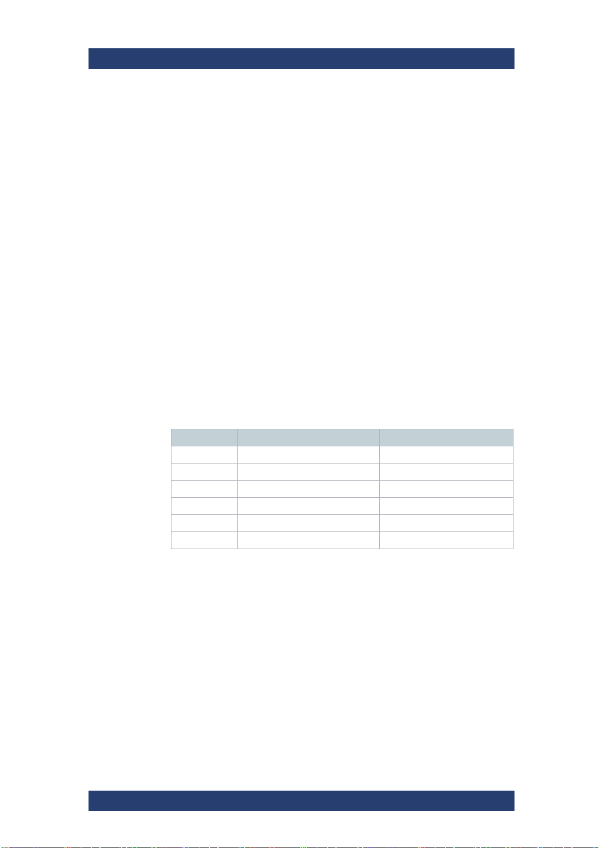
The following drive bundle options are available:
Name Bundle content Usable size estimate in TB
SBO-B130 HDD bundle 4TB (30 drives) 99
SBO-B131 HDD bundle 8TB (30 drives) 198
SBO-B132 HDD bundle 16TB (30 drives) 396
SBO-B140 SSD bundle 1.92TB (30 drives) 47
SBO-B141 SSD bundle 3.84TB (30 drives) 95
SBO-B142 SSD bundle 7.68TB (30 drives) 190
Additional HBA Options
The following HBA options (backbone and networking) are also available:
● 100GbE Dual Port Ethernet Card
● 200GbE Dual Port Ethernet Card
22
User Manual | 2902.5569.01 - 07
SpycerNode SC
Certified Clients for SpycerNode SC
Certified Clients for SpycerNode SC
There are different ways to connect clients to SpycerNode SC.
SpycerNode SC exposes the storage via the NSD (Network Shared Disk)
protocol to the ethernet network. A NSD client is any server or workstation
that has the native Spectrum Scale protocol installed and is designated to
operate as a client. Physically reading or writing user data to the SAN disks
is done on behalf of the NSD clients that trigger the disk operations
The following operating systems are supported for native Spectrum Scale 5
clients:
● Windows 10
● RHEL/CentOS 7.7 (or later)
● SLES12 SP1 (or later)
● Ubuntu 16.04 and 18.04.1
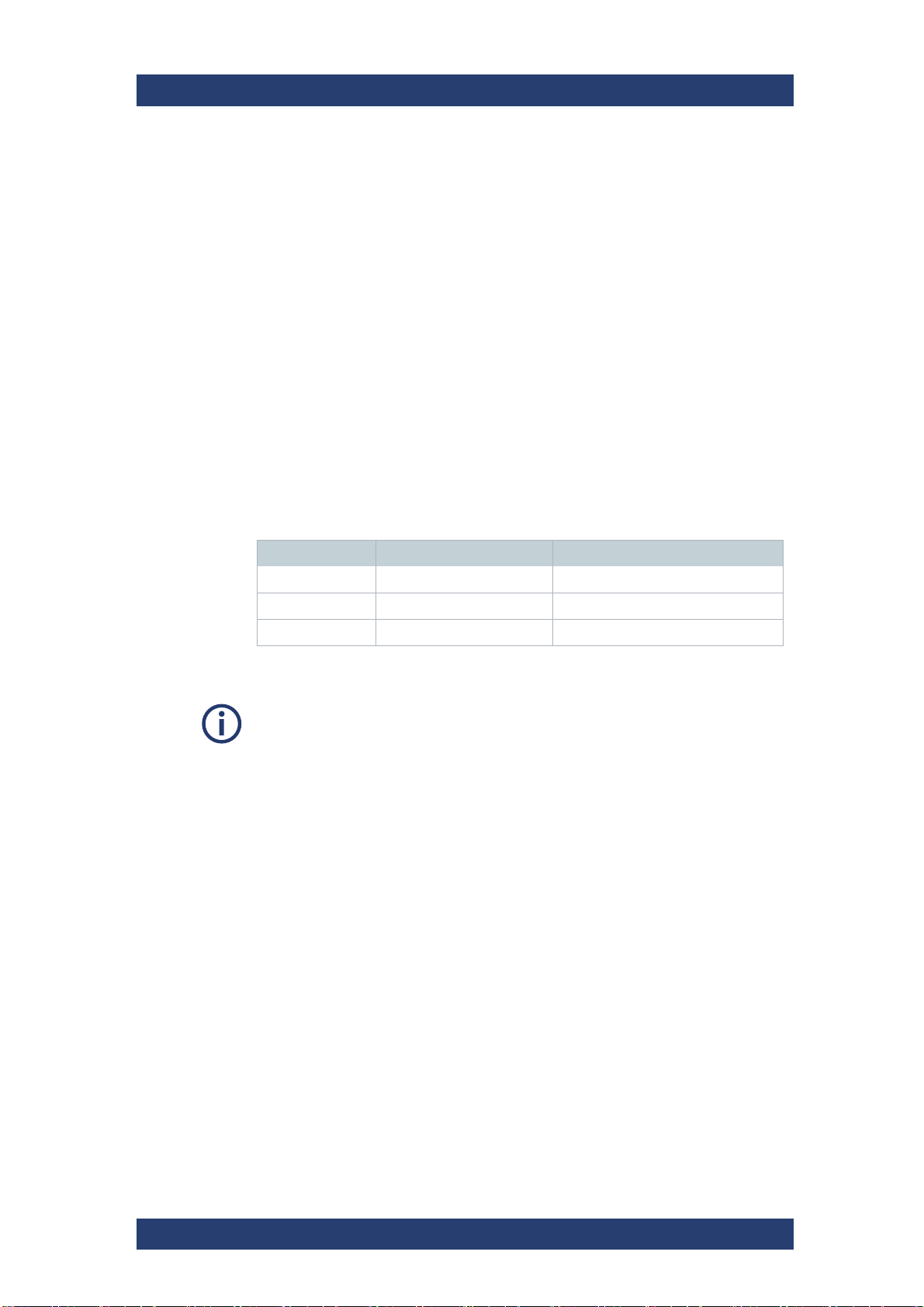
Besides the native clients the following file sharing protocols are supported:
Product Description
Protocol Version Operating System
Samba SMBv2, SMBv3 Linux/Windows/OSX
NFS NFSv4 Linux/OSX
FTP - Linux/Windows/OSX
Performance values may differ for individual client configuration.
User Manual | 2902.5569.01 - 07
23
Product Description
Type plate
Type Plate and Serial Number
Type Plate and Serial Number
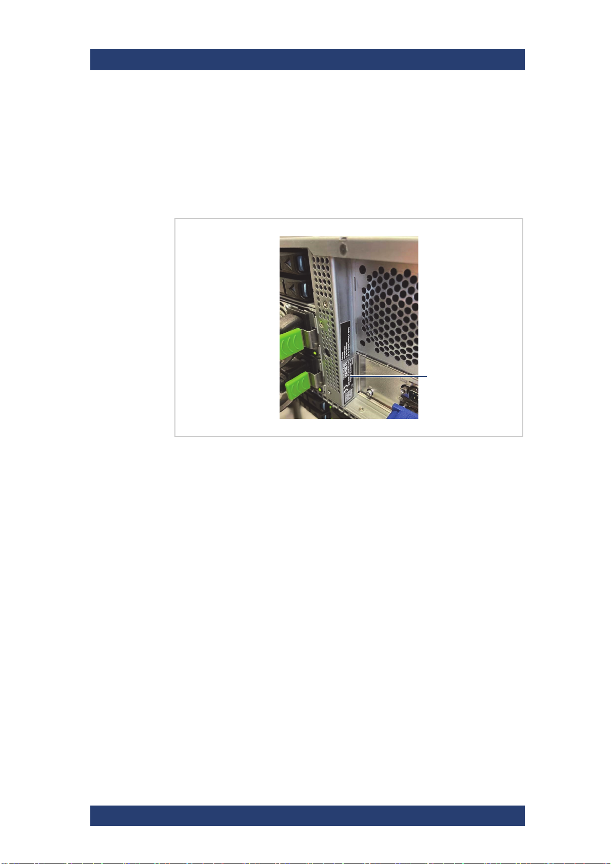
The serial number of the system is located on the type plate.
Type Plate
The type plate itself is located on the back panel of the system (bottom left).
SpycerNode SC
Location of the type plate
The type plate contains the following information:
● Type
● Article number
● Serial number, see also "Serial Number" (page 25)
● Product description
24
User Manual | 2902.5569.01 - 07
SpycerNode SC
Product Description
Type Plate and Serial Number
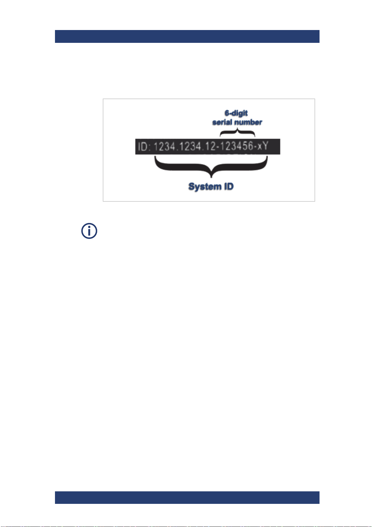
Serial Number
The serial number is part of the system ID. It is the 6-digit number that
comes after the article number:
Serial number as part of the system ID
This 6-digit serial number is used as password when logging in to:
● R&S
● IPMI login (username: "admin"). For systems built after April 2022
®
Device Manager web frontend (username: "administrator")
prepend "rs" to the beginning of the serial number (e.g "rs123456").
User Manual | 2902.5569.01 - 07
25
Product Description
Operating panel &
system status LEDs
Backplane status
LEDs
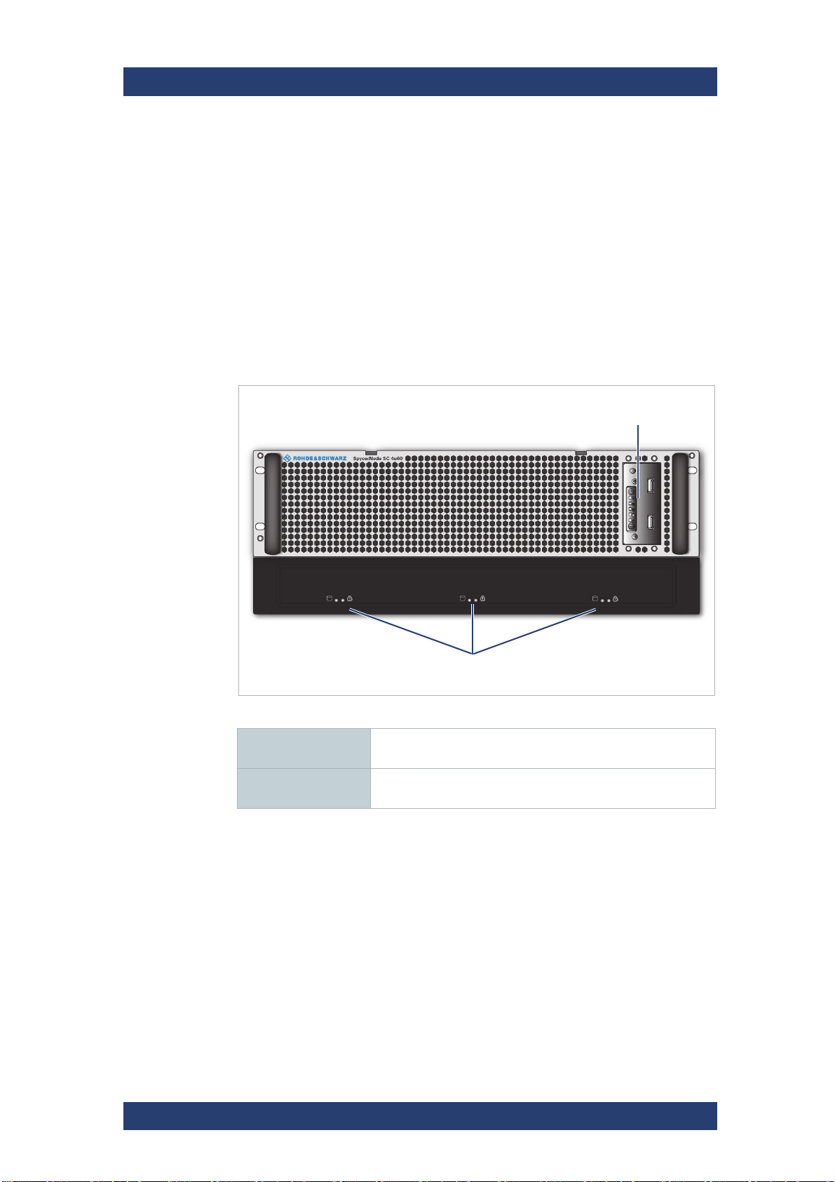
The Front of the System
The Front of the System
This section gives an overview of the front of the system.
The following topics are covered:
● Front Panel (page 26)
● Operating Panel (page 27)
Front Panel
The front of the system is equipped with a front cover for mechanical protection and sufficient air circulation.
SpycerNode SC
Front Panel
Operating panel &
system status LEDs
Backplane status
LEDs
See "Operating Panel" (page 27).
See "Backplane Status LEDs" (page 27).
26
User Manual | 2902.5569.01 - 07
SpycerNode SC
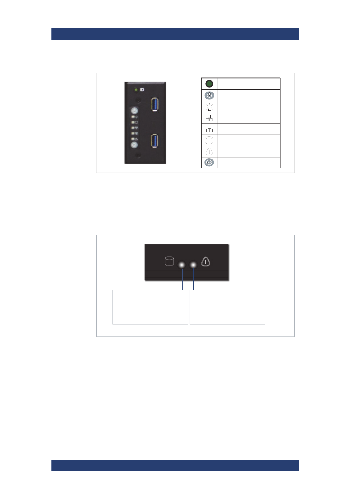
Power On/Off
System Power LED
!
H
System HDD Activity LED
Service ID LED On/Off
System Reset
LAN 1 LED
LAN 2 LED
ID System Indicator
LED11:
Blue (ON) - Drive OK
OFF - Drive not connected or
power is off.
LED12:
Red (ON) - Drive failure
OFF - Normal operation
Product Description
The Front of the System
Operating Panel
Operating Panel & Status LEDs
Backplane Status LEDs
There are three drive backplanes hosting the storage drives (with 20 drive
trays each). The status of each backplane is displayed on the lower front
panel of the system.
Backplane Status LEDs
User Manual | 2902.5569.01 - 07
27
Product Description
Drives
Drives
Drives in SpycerNode SC are protected by RAID 6. RAID 6 uses two parity
stripes to distribute data across the set of drives. It allows for two disk failures within the RAID set before any data is lost. All drives provide error
detection and correction capabilities. These are reported to the application in
line with the SCSI specifications.
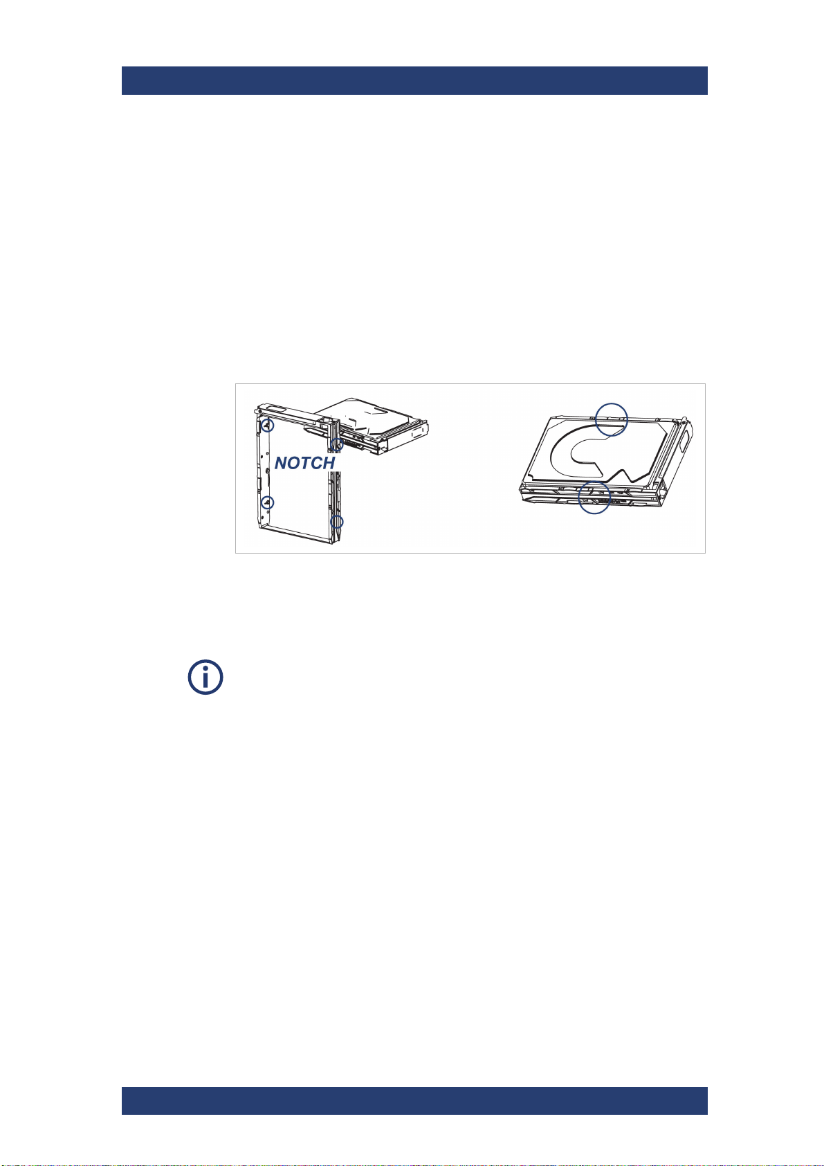
Carriers
Drive carriers are used to hold the storage disks. A drive carrier houses a
single 3.5 SAS drive or, with an adapter, a 2.5 inch SAS SSD.
SpycerNode SC
Drive carrier (SAS drive)
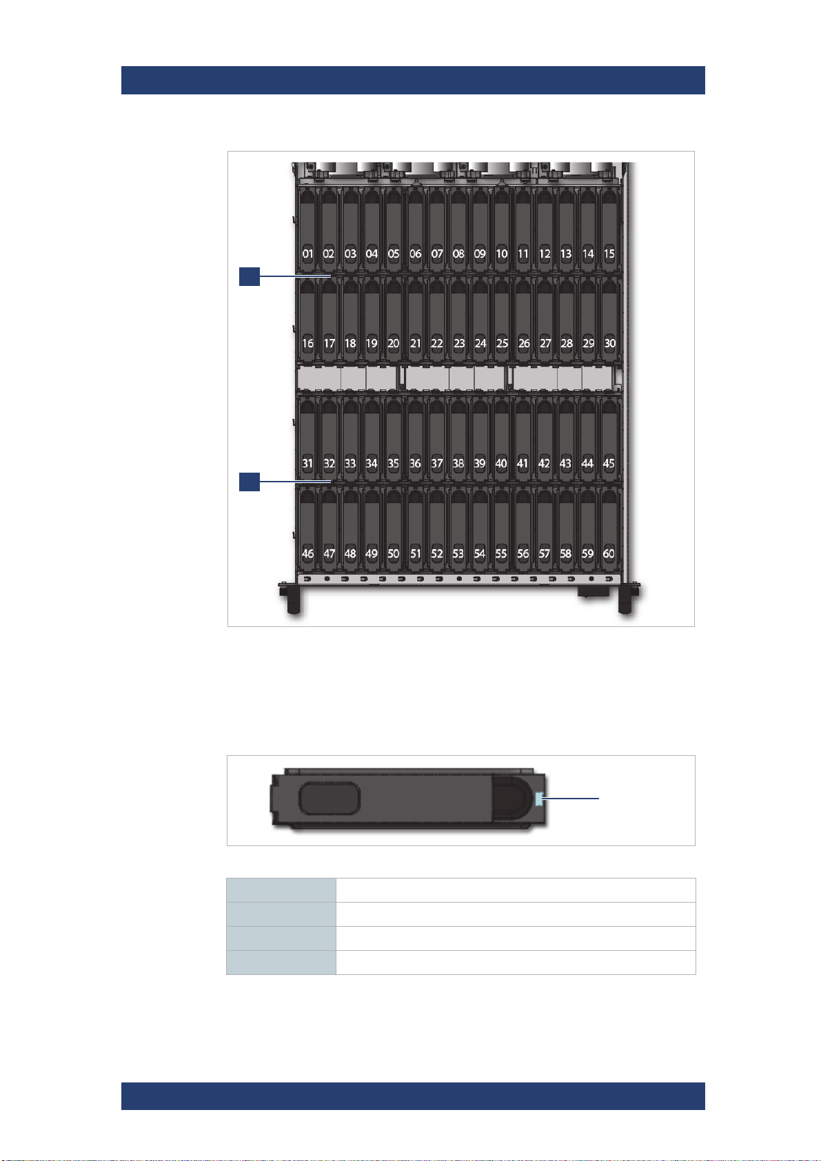
Disks Layout
At shipment, the hard disks are delivered separately and therefore have to be
installed before putting the system into operation, see also "Installing the
Drives" (page 42).
The drives are divided into two drives sets (01 - 30 and 31 - 60) for a total of
60 drives. A system with half capacity will have only the first set populated.
The layout of the drive sets is as follows:
28
User Manual | 2902.5569.01 - 07
SpycerNode SC
2
1
Disk status LED
Product Description
Drives
Drive mapping
Status LED
The drive carriers have a status LED to indicate the current state of the
drive.
HB and EB drive carrier LEDs
Blue (ON) Disk connected
Blue (blinking) Disk activity
Red (blinking) Rebuild status for RAID
Red Disk failure
User Manual | 2902.5569.01 - 07
29
Product Description
10bay HDD cage
ATX connector
pannel
Power supply units
Storage network
The Rear of the System
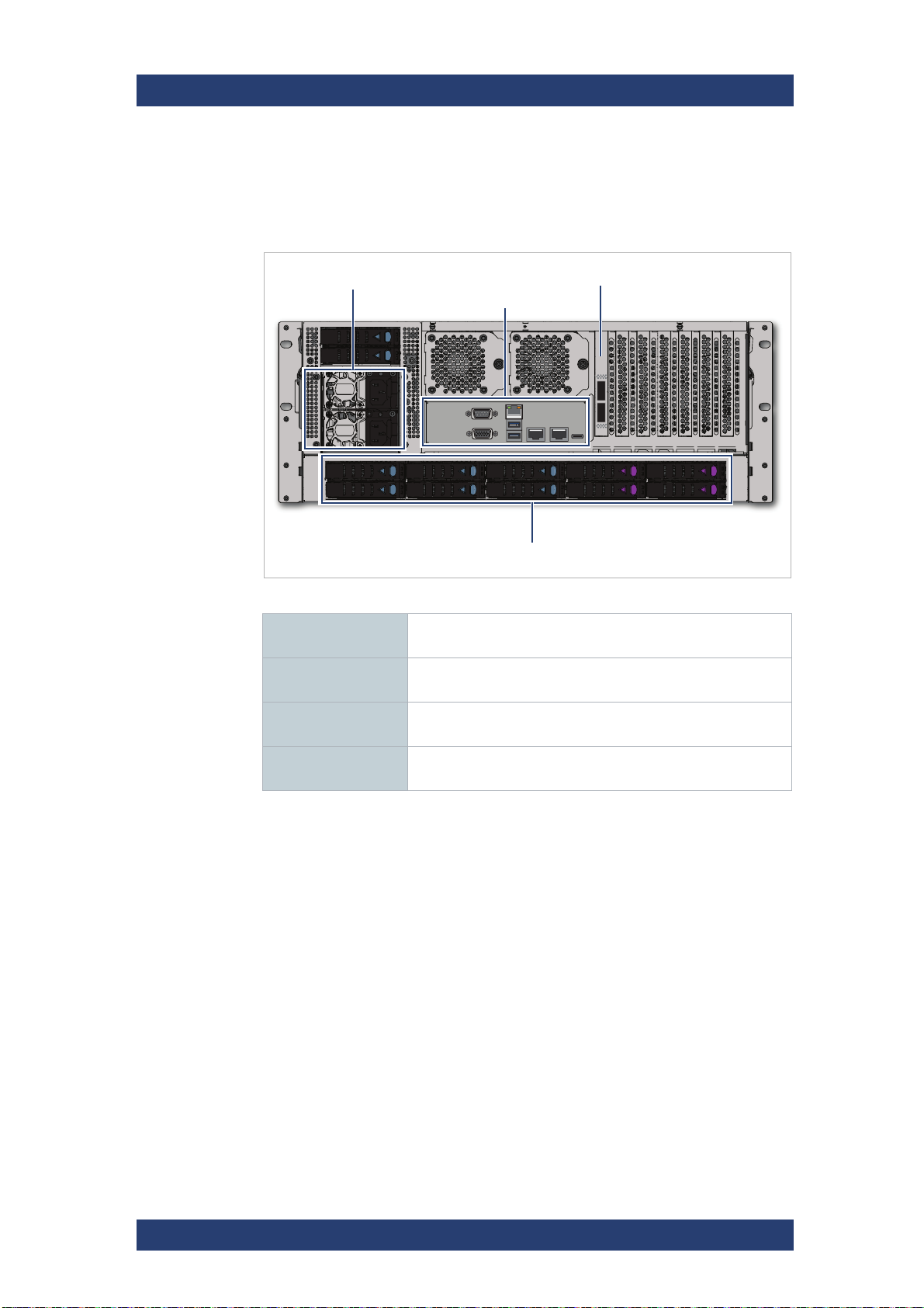
The Rear of the System
The rear of the chassis provides access to the I/O modules, the power
supply units, and the system drives.
SpycerNode SC
Back panel
Power supply units Dual redundant power supply units, see also "Power Supply
ATX connector
panel
Storage network
connection
10bay HDD cage Hosts the system disks for the operating system and meta-
Units" (page 31)
Provides the standard connectors of the computer system,
see also "ATX Panel" (page 32)
Provides (optional) connection to external storage devices
with either a 100GbE or a 200GbE Dual Port Ethernet Card.
data, see also "System Disks" (page 33).
30
User Manual | 2902.5569.01 - 07
SpycerNode SC
Product Description
The Rear of the System
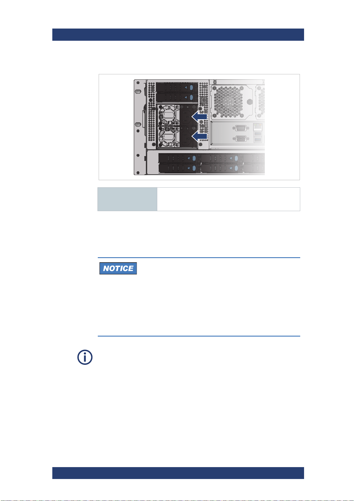
Power Supply Units
Power connectors Power is provided by two 1600 W PSU‘s These require an
input of 200 to 240 VAC at 50 to 60 Hz. The IEC C14 AC
connector requires a C13 AC jack.
Dual PSUs provide redundant power for the system: if one PSU fails, the
other will keep the system running while you replace the faulty module. The
PSUs are hot-swappable.
System Damage
Replacement of a PSU can be performed while the system is running, but
the procedure must be completed immediately after the removal of the
defective PSU, otherwise a continued operation of the system cannot be
guaranteed.
Change a failed power supply unit immediately. Ensure you have a
replacement PSU before you remove the defective unit.
For information on how to exchange a PSU see "Replacing a Power Supply
Unit" (page 88).
User Manual | 2902.5569.01 - 07
31
Product Description
VGA
2 x USB 3.1 Gen1
2 x LAN RJ-45, 10Gbit
COM1 port
LAN RJ-45 (IPMI), 1Gbit
USB 3.1 Gen2 (type C)
ID System
Indicator
The Rear of the System
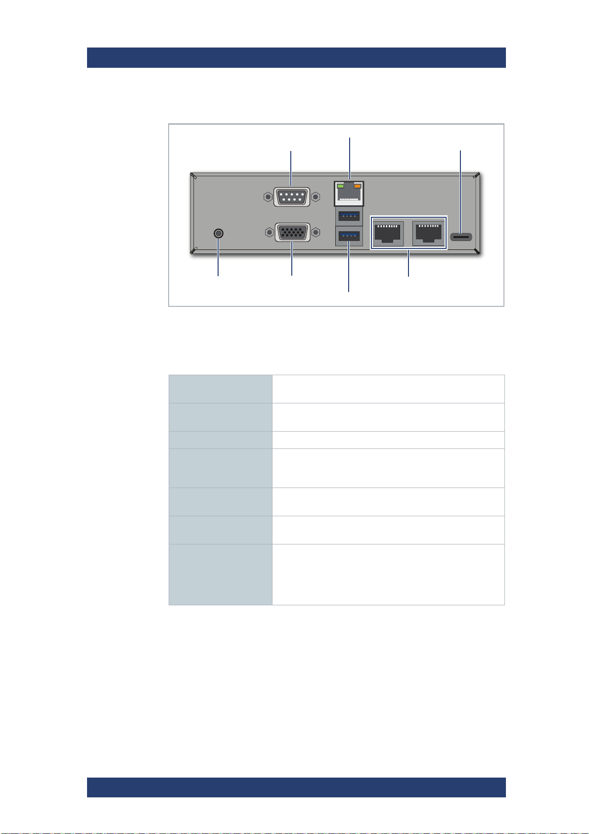
ATX Panel
ATX Panel Connectors
The ATX connector panel on the rear of the R&S system holds the connectors of the computer system. It provides the following connections:
SpycerNode SC
COM1 Port RS232 connector for the connection of serial interface
devices.
LAN RJ-45 (IPMI) 1 Gb Ethernet connection port to connect the system to a
network.
USB 3.1 Gen2 (type C) A type-C USB to connect external devices to the system.
ID System Indicator Press to trigger the green ID LED located on the front of
the system. Useful e.g. to locate the system within a rack
among many other systems.
VGA DB-15 connector (female) to connect a monitor to the
system.
USB 3.1 Gen1 USB connectors to connect external devices to the
system.
2 x LAN RJ-45 2 x 10 Gb Ethernet connection ports to connect the
system to a network. By default, the left network port is
DHCP
set to
whereas the left one is pre-configured to a static 10.0.0.4
IP address.
(Dynamic Host Configuration Protocol),
32
User Manual | 2902.5569.01 - 07
 Loading...