

Rohde&Schwarz R&S®SpycerNode User Manual
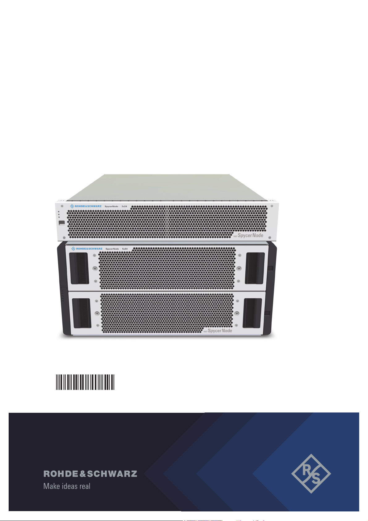
R&S®SpycerNode
User Manual
2902.3266.02 - 10

SpycerNode
© 2022 Rohde & Schwarz GmbH & Co. KG
Hanomaghof 4, 30449 Hanover, Germany
Phone: +49-511-67807-0
Support: https://www.rohde-schwarz.com/support
Internet: https://www.rohde-schwarz.com
Subject to change – Data without tolerance limits is not binding.
R&S® is a registered trademark of Rohde & Schwarz GmbH & Co. KG.
Trade names are trademarks of the owners.
Throughout this manual, products from Rohde & Schwarz are indicated without the ® symbol,
e.g. R&S®SpycerNode is indicated as SpycerNode.
2
User Manual | 2902.3266.02 - 10

SpycerNode
Contents
General .............................................................................................................7
About this Documentation....................................................................................................... 8
Required Reading ................................................................................................................8
Target Group ........................................................................................................................ 8
Additional Documentation .................................................................................................... 8
Safety ................................................................................................................9
For your Safety ....................................................................................................................... 10
General Notes ......................................................................................................................... 11
2U Enclosures .................................................................................................................... 11
5U Enclosure ...................................................................................................................... 12
Product Description ......................................................................................13
Function .................................................................................................................................. 14
Models ..................................................................................................................................... 15
Storage Extensions ............................................................................................................ 15
Enclosure Overview ........................................................................................................... 16
Certified Clients for SpycerNode .......................................................................................... 17
System ID and Serial Number ............................................................................................... 18
System ID ........................................................................................................................... 18
Serial Number .................................................................................................................... 18
The Front of the System ........................................................................................................ 19
Enclosure Front .................................................................................................................. 19
Operating Panel (2U Enclosures) ....................................................................................... 20
Operating Panel (5U Enclosure) ........................................................................................ 22
Drives ................................................................................................................................. 24
Carriers (2U Enclosures) .................................................................................................... 25
Carriers (5U Enclosure) ...................................................................................................... 27
The Rear of the System..........................................................................................................28
I/O Modules ........................................................................................................................ 29
AP-LS I/O Module .............................................................................................................. 29
JBOD I/O Module ............................................................................................................... 31
Power Cooling Module (2U Enclosures)............................................................................. 33
Fan Cooling Modules (5U Enclosure)................................................................................. 34
Power Supply Unit (5U Enclosure) ..................................................................................... 36
Installation ......................................................................................................39
Unpacking the System ........................................................................................................... 40
Mounting the System into a Rack ......................................................................................... 41
Rack System Precautions .................................................................................................. 41
2U Enclosures .................................................................................................................... 43
5U Enclosures .................................................................................................................... 44
Installing the Drives ............................................................................................................... 46
5U Enclosure ...................................................................................................................... 46
2U Enclosures .................................................................................................................... 48
Connecting the Power Source .............................................................................................. 49
2U Enclosures .................................................................................................................... 49
5U Enclosures .................................................................................................................... 49
User Manual | 2902.3266.02 - 10
3

SpycerNode
Connecting the I/O Modules .................................................................................................. 50
2U Enclosures .................................................................................................................... 50
5U Enclosures .................................................................................................................... 51
Connecting to Networks ........................................................................................................ 52
Starting the System ................................................................................................................ 53
Shutting down the System .................................................................................................... 54
Configuration ................................................................................................ 55
R&S Network Switch Configuration ...................................................................................... 56
Configure a static IP for Management Interface ................................................................. 56
Configure MTU ...................................................................................................................57
Optional .............................................................................................................................. 57
Setting the Unit Identification Number ................................................................................. 59
Initial Setup ............................................................................................................................. 60
Using Dynamic Host Configuration Protocol (DHCP) ......................................................... 60
Using Static IP .................................................................................................................... 67
Installing the Spectrum Scale Client .................................................................................... 74
Installing under Linux ......................................................................................................... 74
Installing under Windows ................................................................................................... 75
Adding a Native Spectrum Scale Client to an Existing Cluster .......................................... 82
Removing a Native Spectrum Scale Client ........................................................................ 83
Operation ....................................................................................................... 85
Using the R&S®Device Manger............................................................................................. 86
Administration............................................................................................... 89
System Update ........................................................................................................................ 90
System Monitoring ................................................................................................................. 91
Monitoring through SNMP .................................................................................................. 91
Monitoring through the Device Manager ............................................................................ 92
Monitoring Disk Arrays ....................................................................................................... 94
Maintenance .................................................................................................. 97
Safety Instructions ................................................................................................................. 98
Replacing an I/O Module ........................................................................................................ 99
Removing an I/O Module .................................................................................................... 99
Installing an I/O Module .................................................................................................... 100
2U Enclosures ....................................................................................................................... 101
Removing and Mounting the Front Plate .......................................................................... 101
Replacing a Power Cooling Module ................................................................................. 102
Replacing a Drive Carrier (2u12) ...................................................................................... 104
Replacing a Drive Carrier (2u24) ...................................................................................... 108
Dummy Carrier Removal/Replacement ............................................................................ 111
Replacing a Power Supply Unit ........................................................................................ 111
5U Enclosures ....................................................................................................................... 113
General Procedures ......................................................................................................... 113
Replacing a Drive Carrier ................................................................................................. 115
Replacing a Cooling Module ............................................................................................ 118
Replacing a Power Supply Unit ........................................................................................ 120
Working with the R&S Installer (RSI) ........................................................ 123
Types of RSI Packages ........................................................................................................ 124
4
User Manual | 2902.3266.02 - 10

SpycerNode
Using an RSI ......................................................................................................................... 125
RSI Troubleshooting ............................................................................................................ 127
Logs .................................................................................................................................. 127
Error Codes ...................................................................................................................... 127
Transport ......................................................................................................131
Safety Notes .......................................................................................................................... 132
Packing the System..............................................................................................................133
2U Enclosures .................................................................................................................. 133
5U Enclosures .................................................................................................................. 134
Index .............................................................................................................135
User Manual | 2902.3266.02 - 10
5

SpycerNode
6
User Manual | 2902.3266.02 - 10

General
This chapter includes the following section:
GeneralSpycerNode
● About this Documentation (page 8)
User Manual | 2902.3266.02 - 10
7

General
About this Documentation
About this Documentation
This documentation informs you about the installation of the SpycerNode
hardware, a storage system by Rohde & Schwarz, its operation as well as all
connection possibilities. Furthermore, it describes maintenance tasks that
you may carry out on your own.
Required Reading
Each person who is responsible for installation, operation, maintenance or
setting of the system has to read and understand this manual.
Target Group
To use this manual you should know how to handle computer equipment.
Furthermore, to connect the R&S system to a network you should have
experience as a network administrator and know how to set up the required
network connections on the installation site in hard- as well as software.
SpycerNode
When performing maintenance tasks on the hardware of the R&S system,
you must be qualified to work on, repair and test electrical equipment.
Additional Documentation
Following documents have to be heeded while working with SpycerNode:
● Data Sheet
The complete documentation can be downloaded from
https://gloris.rohde-schwarz.com after registering/logging in to access
restricted information. There you may find updated manuals and further
information as well.
8
User Manual | 2902.3266.02 - 10

Safety
SafetySpycerNode
This chapter is divided into the following sections:
● For your Safety (page 10)
● General Notes (page 11)
User Manual | 2902.3266.02 - 10
9

Safety
For your Safety
For your Safety
The product documentation helps you to use SpycerNode safely and efficiently. Keep the product documentation in a safe place and pass it on to the
subsequent users. Use SpycerNode only in its designated purpose as
described in the product documentation. Observe the performance limits and
operating conditions stated in the specification (data sheet).
Safety information is part of the product documentation. It warns you about
the potential dangers and gives instructions how to prevent personal injury or
damage caused by dangerous situations.
Safety information is provided as follows:
● In the "Basic Safety Instructions", safety issues are grouped according to
subjects.
● Throughout the documentation, safety instructions are provided when
you must pay attention during setup or operation.
Always read the safety instructions carefully. Make sure to fully comply with
them. Do not take risks and do not underestimate the potential danger of
small details such as a damaged power cable.
SpycerNode
10
User Manual | 2902.3266.02 - 10

SpycerNode
General Notes
Please observe the following general important notes:
● Do not lift the enclosure by the handles on the rear modules or the
PCMs. They are not designed to take the weight. Only lift from underneath the main chassis.
● If this equipment is used in a manner not specified by the manufacturer,
the protection provided by the equipment may be impaired.
● The optional RJ45 socket on the I/O module, it is for Ethernet connection
only and must not be connected to a telecommunications network.
● All plug-in modules and blank plates are part of the fire enclosure and
must only be removed when a replacement can be immediately added.
The system must not be run without all modules or blanks in place.
● Unplug the unit before you move it or if you think it has become
damaged in any way.
● The plug on the power supply cord is used as the main disconnect
device. Ensure that the socket outlets are located near the equipment
and are easily accessible.
● When powered by multiple AC sources, disconnect all supply power for
complete isolation.
● In order to comply with applicable safety, emission and thermal require-
ments no covers should be removed and all bays must be populated with
plug-in modules or blanks.
● The power connection should always be disconnected prior to removal of
a PCM/PSU from the enclosure.
● A safe electrical earth connection must be provided to the power supply
cords. Check the grounding of the enclosure before applying power.
● Provide a suitable power source with electrical overload protection to
meet the requirements laid down in the technical specification.
● Do not remove PCMs, Cooling Modules, PSUs or I/O Modules unless
you have a replacement model of the correct type ready for insertion.
● Connect the system to an uninterruptible power supply redundantly on
two phases.
● It is recommended that you fit and check a suitable anti-static wrist or
ankle strap and observe all conventional ESD precautions when
handling plug-in modules and components. Avoid contact with backplane
components and module connectors, etc.
Safety
General Notes
2U Enclosures
Please observe the following general important notes:
● An enclosure can weigh up to to 26 kg (57lb) depending on configura-
tion. Do not try to lift the enclosure by yourself.
● It is advisable to remove all plug-in modules to minimize weight before
lifting the enclosure.
● The enclosure must only be operated from a power supply input voltage
range of 100-240 VAC.
User Manual | 2902.3266.02 - 10
11

Safety
General Notes
SpycerNode
● When bifurcated power cords (‘Y’ leads) are used, they must only be
connected to a supply range of 200-240 V.
● A faulty PCM must be replaced with a fully operational module within 24
hours.
5U Enclosure
Please observe the following general important notes:
● Important: The enclosure must be mounted in a rack.
● An unpopulated enclosure can weigh up to 45kg (100lb). Use appro-
priate lifting methods.
● A fully populated enclosure weighs 135kg (298lb). Only lift the enclosure
when the drawers are empty and latched closed. Do not attempt to lift
the enclosure when populated with drives.
● When closing the drawers, do so firmly, ensuring the latches are
engaged.
● Do not attempt to disassemble the rear sub-chassis from the enclosure.
● Operating temperatures inside the enclosure drawers can reach up to
60°C. Take care when opening drawers and removing drive carriers.
● If any component of the product fails, consult your storage vendor.
● For North American use, each branch circuit must be rated for 20A.
● The equipment is suitable for connection to an IT power system
(Norway), when mounted in a Restricted Access Location where equipotential bonding has been applied by a service person.
● Double pole/neutral fusing in PSUs.
● Risk of explosion if the battery within the RAID controller is replaced with
an incorrect type. Dispose of used batteries according to the instructions.
There are no user serviceable parts within the RAID controller.
● Due to product acoustics it is recommended that users wear ear protec-
tion for any prolonged exposure.
● To prevent over-turning, drawer interlocks stop users from opening both
drawers at the same time. Do not attempt to force open a drawer when
the other drawer is already open.
● The product ratings are: voltage: 200 to 240 VAC; current: 16A or 13A
per inlet; frequency: 50 to 60 Hz. This information can also be found on
the back of the PSUs.
12
User Manual | 2902.3266.02 - 10

Product Description
This chapter is divided into the following sections:
● Function (page 14)
● Models (page 15)
● Certified Clients for SpycerNode (page 17)
● System ID and Serial Number (page 18)
● The Front of the System (page 19)
● The Rear of the System (page 28)
Product DescriptionSpycerNode
User Manual | 2902.3266.02 - 10
13

Product Description
Function
Function
With SpycerNode, Rohde & Schwarz has brought enterprise-class storage
features to the media and entertainment market segment. Today’s exponential growth of data and transactions is demanding larger and larger amounts
of unstructured data storage and management across diverse workloads. As
each department or division attempts to satisfy its own storage and performance needs, your organization can find itself with many disparate systems
isolated from each other. This can result in expensive resource duplication,
complicated management and isolated pools of data. In addition, the
resulting islands of information may hold valuable insights that may not be
accessible in such a fragmented environment. Traditional RAID is no longer
an effective mechanism for data protection for modern disk drives, since it
can take several hours or even days to rebuild a failed drive. Advanced
erasure coding to spread the data and shorten recovery time is required to
avoid the catastrophic results of multi-disk failures with traditional RAID.
The R&S SpycerNode with its ideal physical sizes as a building block is easy
to install and deploy. IT managers appreciate features such as two-digit
front-panel shelf ID, activity and status indicators for all key components,
alarms and lockable carriers. With a “no single point of failure” design and
support for both dual ported NL-SAS and dual ported SSD-drives, the R&S
SpycerNode is ready to fulfill a wide variety of applications.
SpycerNode
14
User Manual | 2902.3266.02 - 10

SpycerNode
Models
Product Description
Models
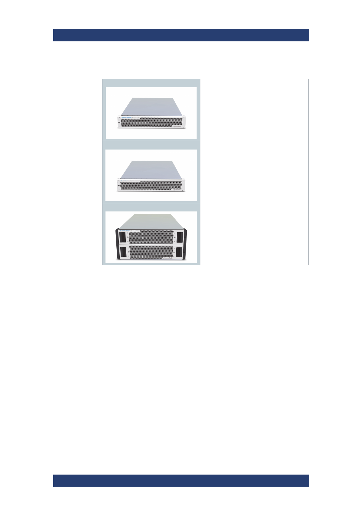
SpycerNode is available in the following hardware platforms with different
configurations:
● SpycerNode 2U12 main unit (including appliance controllers)
● SpycerNode 2U24 main unit (including appliance controllers)
● SpycerNode 5U84 main unit (including appliance controllers)
Storage Extensions
For all systems the following storage extensions are available:
● SpycerNode 2U12JB unit (including SAS expanders)
● SpycerNode 2U24JB unit (including SAS expanders)
● SpycerNode 5U84JB unit (including SAS expanders)
2U12/ 2U12JB
Available drive bundles:
● HDD bundle 96 TB (12 HCS 8TB drives)
● SSD bundle 11TB (12 SAS SSD 960GB drives)
● SSD bundle 23TB (12 SAS SSD 1920GB drives)
● SSD bundle 43TB (12 SAS SSD 3840GB drives)
2U24/ 2U24JB
Available drive bundles:
● SSD Bundle 23TB (24 SAS SSD 960GB drives)
● SSD Bundle 46TB (24 SAS SSD 1920GB drives)
● SSD Bundle 92TB (24 SAS SSD 3840GB drives)
5U84/ 5U84JB
Available drive bundles:
● HDD Bundle 336TB (42 HCS 8TB drives)
● SSD Bundle 40TB (42 SAS SSD 960GB drives)
● SSD Bundle 80TB (42 SAS SSD 1920GB drives)
● SSD Bundle 160TB (42 SAS SSD 3840GB drives)
User Manual | 2902.3266.02 - 10
15
Product Description
Models
Enclosure Overview
SpycerNode
SpycerNode 2U12/2U12JB
• 2U high, 65 cm length
• 12 x 3.5” SAS drives
• 2 x 764W power cooling modules
• LS controllers: 2 x 1U
• SBB 2.0 compliant
SpycerNode 2U24/2U24JB
• 2U high, 65 cm length
• 24 x 2.5” SAS SSD drives
• 2 x 764W power cooling modules
• 2 x controllers
• SBB 2.0 compliant
SpycerNode 5U84/5U84JB
• 5U high, 96cm length
• 84 x 3.5” high capacity SAS drives
• 2 x 2200W power supply units
• 2 controllers
• 5 x fan modules
16
User Manual | 2902.3266.02 - 10

SpycerNode
Certified Clients for SpycerNode
There are different ways to connect clients to SpycerNode.
SpycerNode exposes the storage via the NSD (Network Shared Disk)
protocol to the ethernet network. A NSD client is any server or workstation
that has the native Spectrum Scale protocol installed and is designated to
operate as a client. Physically reading or writing user data to the SAN disks
is done on behalf of the NSD clients that trigger the disk operations
The following operating systems are supported for native Spectrum Scale 5
clients:
● Windows 10
● RHEL/CentOS 7.1 (or later)
● SLES12 SP1 (or later)
● Ubuntu 16.04 and 18.04.1
Besides the native clients following file sharing protocols are supported:
Product Description
Certified Clients for SpycerNode
Protocol Ver sion Operating System
Samba SMBv2, SMBv3 Linux/Windows/OSX
NFS NFSv4 Linux/OSX
FTP - Linux/Windows/OSX
Performance values may differ for individual client configuration.
User Manual | 2902.3266.02 - 10
17
Product Description
System ID
System ID and Serial Number
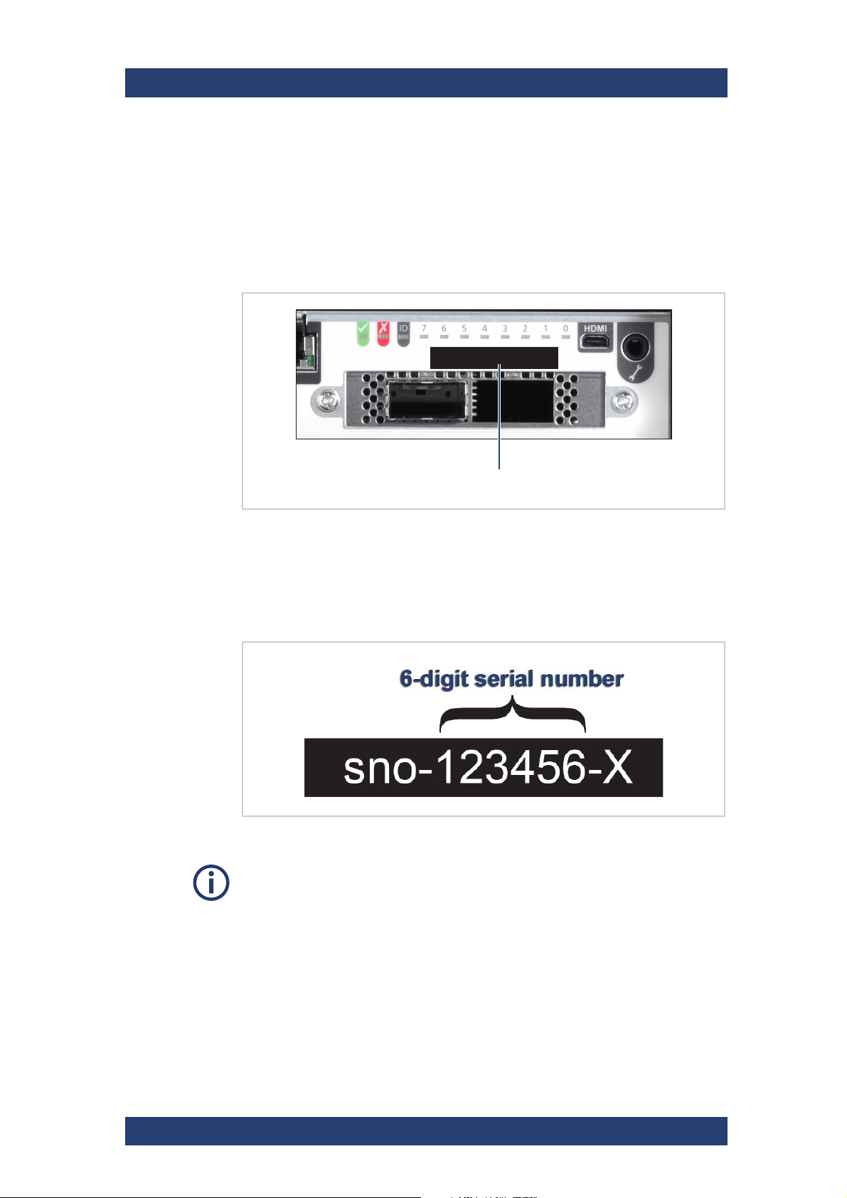
System ID and Serial Number
The system ID and the serial number are located on the back panel of the
system.
System ID
sno-xxxxxx-X
SpycerNode
Location of the system ID
Serial Number
The serial number is part of the system ID and is represented as a 6-digit
number:
Serial number as part of the system ID
This 6-digit serial number is used as password when logging in to:
● R&S
● IPMI login (username: "admin"). For systems built after April 2022
®
Device Manager web frontend (username: "administrator")
prepend "rs" to the beginning of the serial number (e.g "rs123456").
18
User Manual | 2902.3266.02 - 10
SpycerNode
Operating panel
Operating panel
Anti-tamper lock
Drawer status LEDs Drawer status LEDs
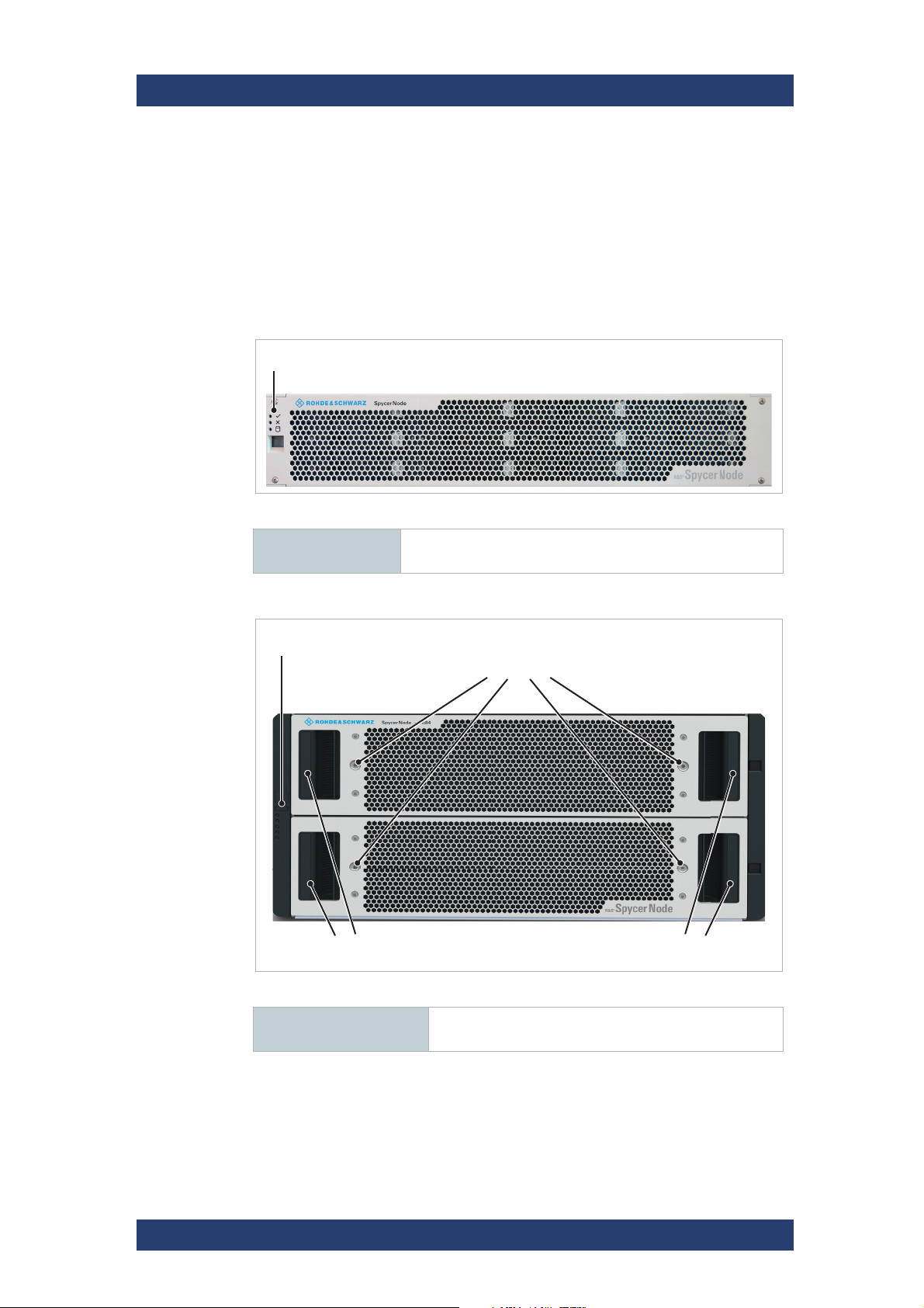
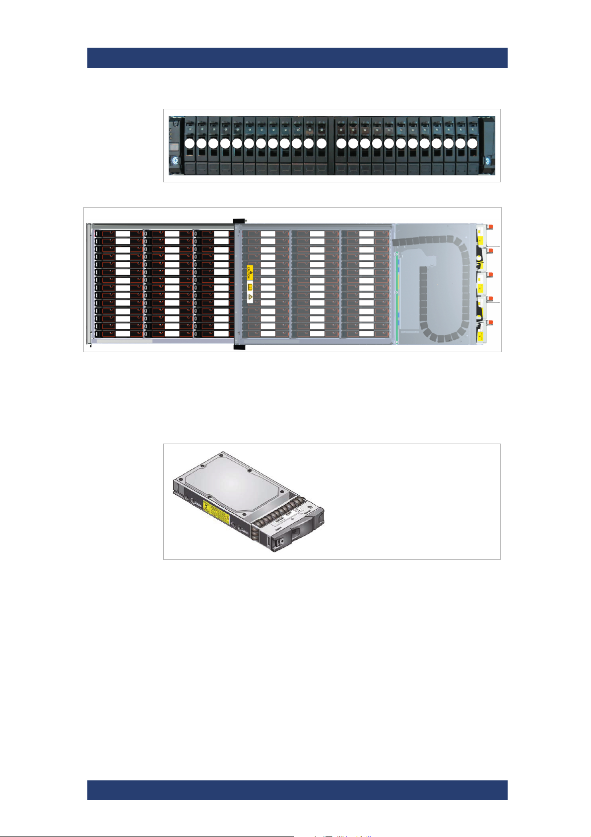
The Front of the System
Enclosure Front
The enclosure has a removable front plate. With a 2U12 and 2U24 enclosure
it is necessary to remove the front plate to get access to the drive slots. For
more information about the drives see chapter “Drives” on page 24.
2u enclosure front
Product Description
The Front of the System
Operating panel For more information see chapter “Operating Panel (2U
5U84 enclosure front
Enclosures)” on page 20
Operating panel For more information see chapter “Operating Panel (5U
User Manual | 2902.3266.02 - 10
Enclosure)” on page 22
19
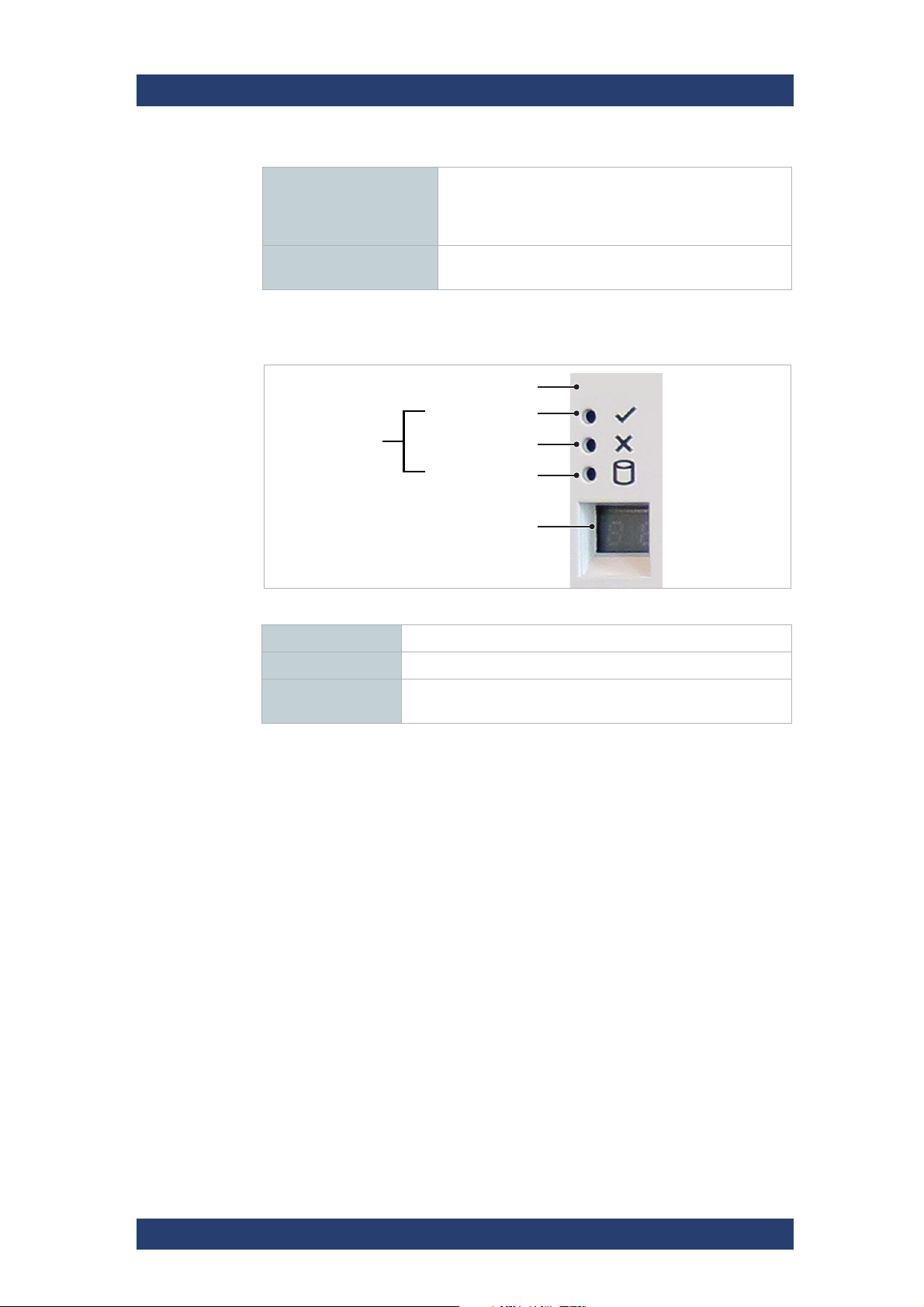
Product Description
System power
Module fault
Logical fault
Unit ID display
Mute Button
LEDs
The Front of the System
Anti-tamper locks The red arrows on the locks will point inwards if the
Drawer 1/2 status For more information see chapter “Drawer LEDs” on
Operating Panel (2U Enclosures)
SpycerNode
locks are disengaged. Unlock them if necessary by
rotating them counterclockwise using a screwdriver with
a torx T20 bit.
page 23.
Operating panel for 2U12 and 2U24
Mute Button (Reserved)
LEDs Fore more information see LEDs.
Unit ID display Displays the enclosure identification number (for use with
multiple enclosure systems).
20
User Manual | 2902.3266.02 - 10

SpycerNode
Product Description
The Front of the System
LEDs
System
power
(green/a
mber)
On On On On Operating panel power on (5s) test
On Off Off X Power on, all functions good
On On X X PCM fault LEDs,
On On X X SBB module
On On X X No module LEDs Enclosure logical fault
On Flash X X Module status
On Flash X X PCM fault LEDs,
On X On X Array in failed or
On X Flash X Arrays in
On Flash X X SES state S1 Enclosure ID setting different from
On X X Flash Enclosure identification or invalid ID
Module
fault
(amber)
Logical
fault
(amber)
LED
display
Associated
LEDs/
alarms
fan fault LEDs
LEDs
LED on SBB
module
fan fault LEDs
degraded state
impacted state
Status
state.
Any PCM fault, fan fault, over or under
temperature
Any SBB module fault
Unknown (invalid or mixed) SBB
module type installed, I
(inter SBB comms) JBOD VPD configuration error
Unknown (invalid or mixed) PCM type
installed, or I2C bus failure (PCM
comms)
Drive failure has occured causing loss
of availability or redundancy
Arrays operating background function
‚start of day‘ setting
selected
2
C bus failure
X = Disregard
User Manual | 2902.3266.02 - 10
21
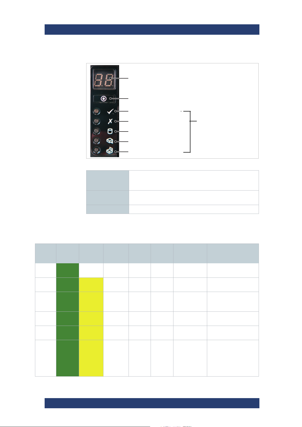
Product Description
Unit ID display
ID switch
Power on / Standby
Module fault
Logical status
Drawer 1 fault
Drawer 2 fault
LEDs
The Front of the System
Operating Panel (5U Enclosure)
Operating panel for 5U Enclosure
Unit ID display Displays the enclosure identification number (for use with
SpycerNode
multiple enclosure systems), but can be configured by the ID
switch.
ID switch Used to set the Unit ID display (refer to chapter “Setting the
Unit Identification Number” on page 59 for details).
LED Fore more information see LEDs.
LEDs
Unit ID
dis-play
Power
(green/
amber)
X On Off Off Off Off Power on, all functions
X On On X X X Single beep,
X On On X Off Off PSU fault
X On On X Off Off SBB module
X On F X Off Off Enclosure logical fault
Module
fault
(amber)
Logical
status
(amber)
Drawer
1 fault
Drawer 2
fault
Associated
LEDs or
Alarms
then double
LEDs, fan fault
LEDs
LEDs
Status
good
Operating panel power
on (5s) test state.
Any PSU fault, fan fault,
over or under temperature
Any SBB module fault
(eg VPD config. error)
X On F X Off Off Module status
22
LED on SBB
module
User Manual | 2902.3266.02 - 10
Unknown (invalid or
mixed) SBB module
type installed, I2C Bus
failure (inter SBB
comms) JBOD VPD
configuration error
SpycerNode
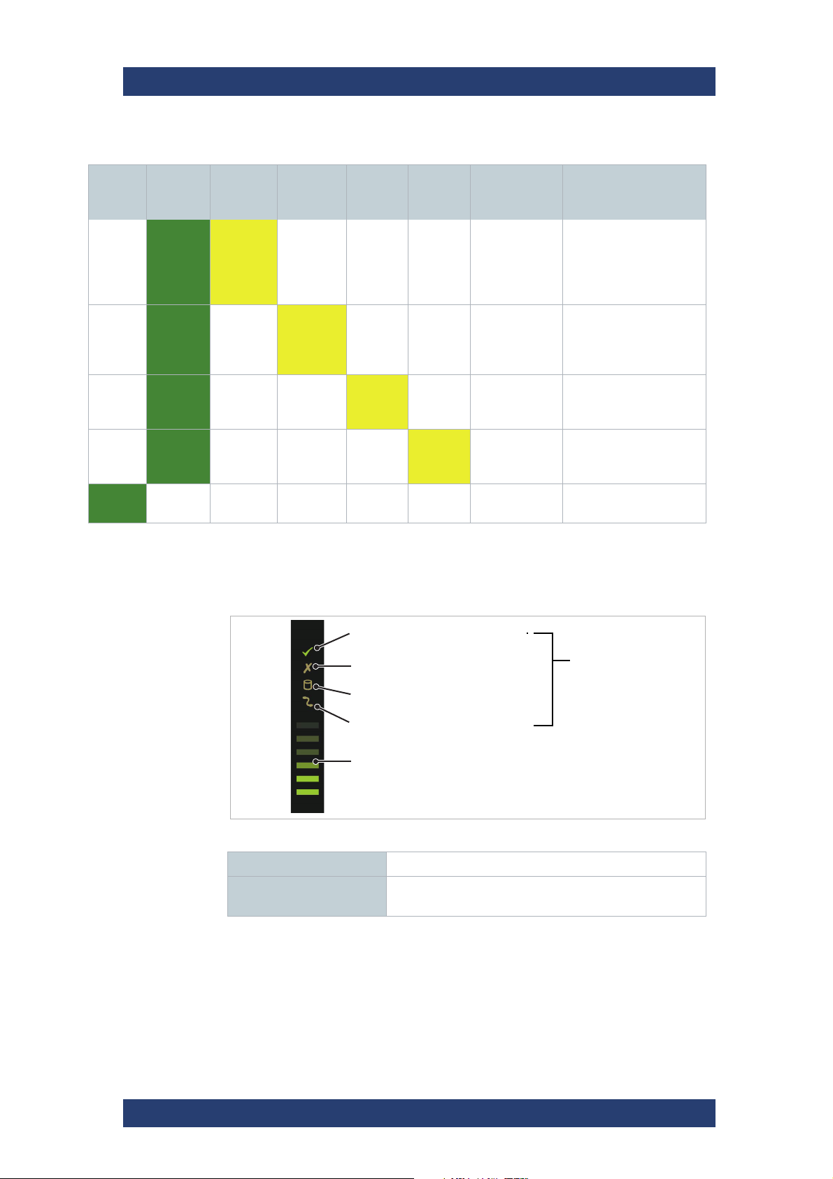
LEDs
Sideplane OK/Power good
Drawer fault
Logical fault
Cable fault
Activity bar graph
Product Description
The Front of the System
Unit ID
dis-play
Power
(green/
amber)
X On F X Off Off PSU fault
X On X On Off Off DDIC fault
X On X X On Off Fault LED on
X On X X Off On Fault LED on
F X X X X X SES controlled enclo-
Module
fault
(amber)
X = Disregard; F = Flashing
Logical
status
(amber)
Drawer
1 fault
Drawer 2
fault
Associated
LEDs or
Alarms
LEDs, fan fault
LEDs
LED, drawer
fault LED
drawer 1
drawer 2
Status
Unknown (invalid or
mixed) PSU module
type installed, or I2C
Bus failure (PSU
comms)
Drive failure has
occurred causing loss
of available or redundancy
Fault present on drawer
1 (drive, cable or fanout
card fault)
Fault present on drawer
2 (drive, cable or fanout
card fault)
sure identify
Drawer LEDs
Drawer LEDs for 5U Enclosure
LEDs Fore more information see the following table.
Activity bar graph Shows the amount of data I/O from zero segments lit
(no I/O) to all six segments lit (maximum I/O).
User Manual | 2902.3266.02 - 10
23
Product Description
01
05
09
02
06
10
03
07
11
04
08
12
The Front of the System
SpycerNode
Sideplane
OK/Power
(green)
On Off Off Off X Sideplane card OK/Ppower
X On X X Off Sideplane card fault
On X On X X Drive fault (host indicated)
Off X X On Off Cable fault
On Off Off Off On* Drive activity
Sideplane
fault (amber)
* The Activity bar graph is a 6-segment drive activity meter, showing activity of the
SAS interface to the sideplane. For zero activity, no segments are lit, scaling lineary
until all segments are lit when the interface is transferring data at full capacity.
X = Disregard
Logical
fault
(amber)
Cable fault
(amber)
Activity bar
graph
(green)
Status
good
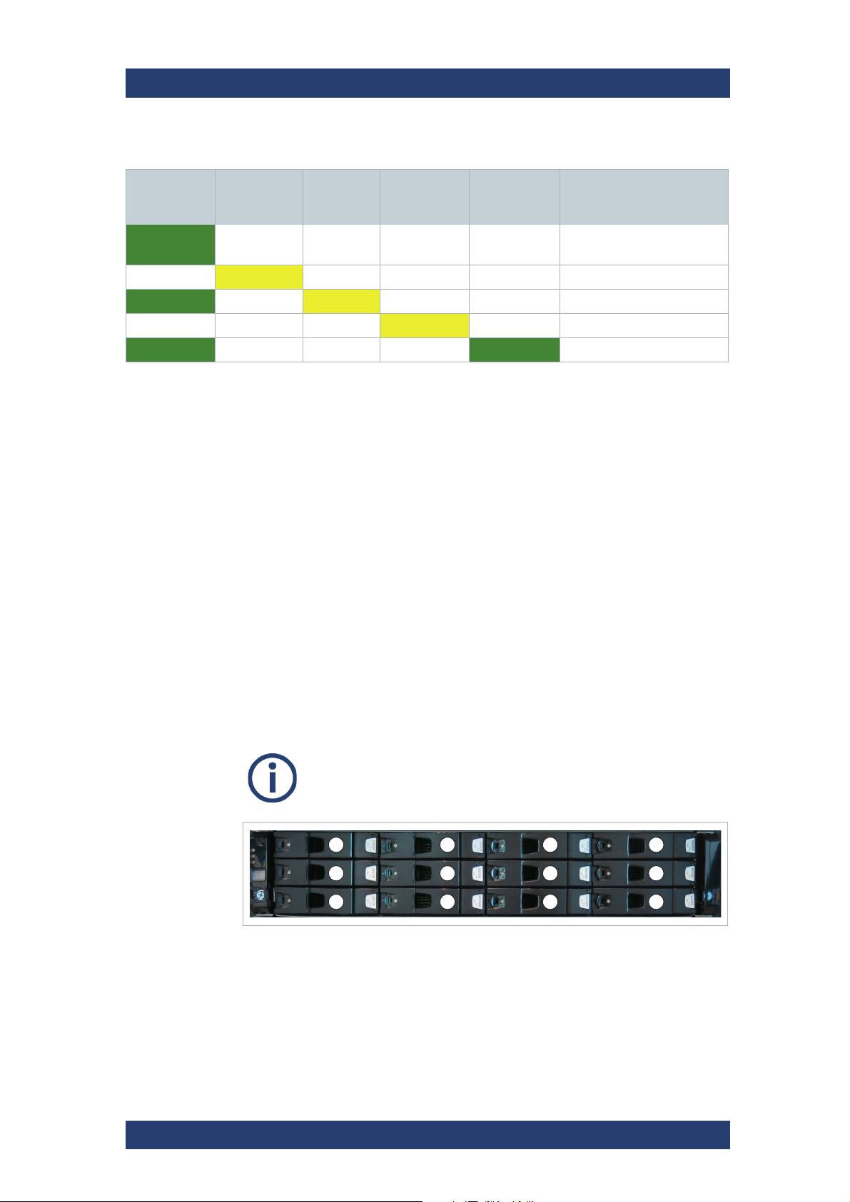
Drives
Drives are provided with dual interfaces and these are connected into separate storage domains. Therefore a fault in one controller does not prevent
the other from operating.
All drives are dual ported, so more than one initiator will be communicating
with the device at any point in time. All drives therefore support SCSI reservations. This is a method to allow a controller to “own” access to a given
device, reserving it for its exclusive use.
All drives provide error detection and correction capabilities. These are
reported to the application in line with the SCSI specifications.
The order of the hard drives in an enclosure is
virtualized, and may bear no resemblance to the order shown here.
Drive mapping for 2U12
24
User Manual | 2902.3266.02 - 10
SpycerNode
Drawer 2 (bottom) Drawer 1 (top)
1-01
1-02
1-03
1-04
1-05
1-06
1-07
1-08
1-09
1-10
1-11
1-12
1-13
1-14
1-15
1-16
1-17
1-18
1-19
1-20
1-21
1-22
1-23
1-24
1-25
1-26
1-27
1-28
1-29
1-30
1-31
1-32
1-33
1-34
1-35
1-36
1-37
1-38
1-39
1-40
1-41
1-42
2-01
2-02
2-03
2-04
2-05
2-06
2-07
2-08
2-09
2-10
2-11
2-12
2-13
2-14
2-15
2-16
2-17
2-18
2-19
2-20
2-21
2-22
2-23
2-24
2-25
2-26
2-27
2-28
2-29
2-30
2-31
2-32
2-33
2-34
2-35
2-36
2-37
2-38
2-39
2-40
2-41
2-42
Product Description
The Front of the System
01 02 03 04 05 06 07 08 09 10 11 12 13 14 15 16 17 18 19 20 21 22 23 24
Drive mapping for 2U24
Drive mapping for 5U Enclosure
Carriers (2U Enclosures)
In 2U12 enclosures a HB carrier is used. It houses a single 3.5 SAS drive or,
with an adapter, a 2.5 inch SAS SSD.
HB drive carrier (SAS drive)
User Manual | 2902.3266.02 - 10
25
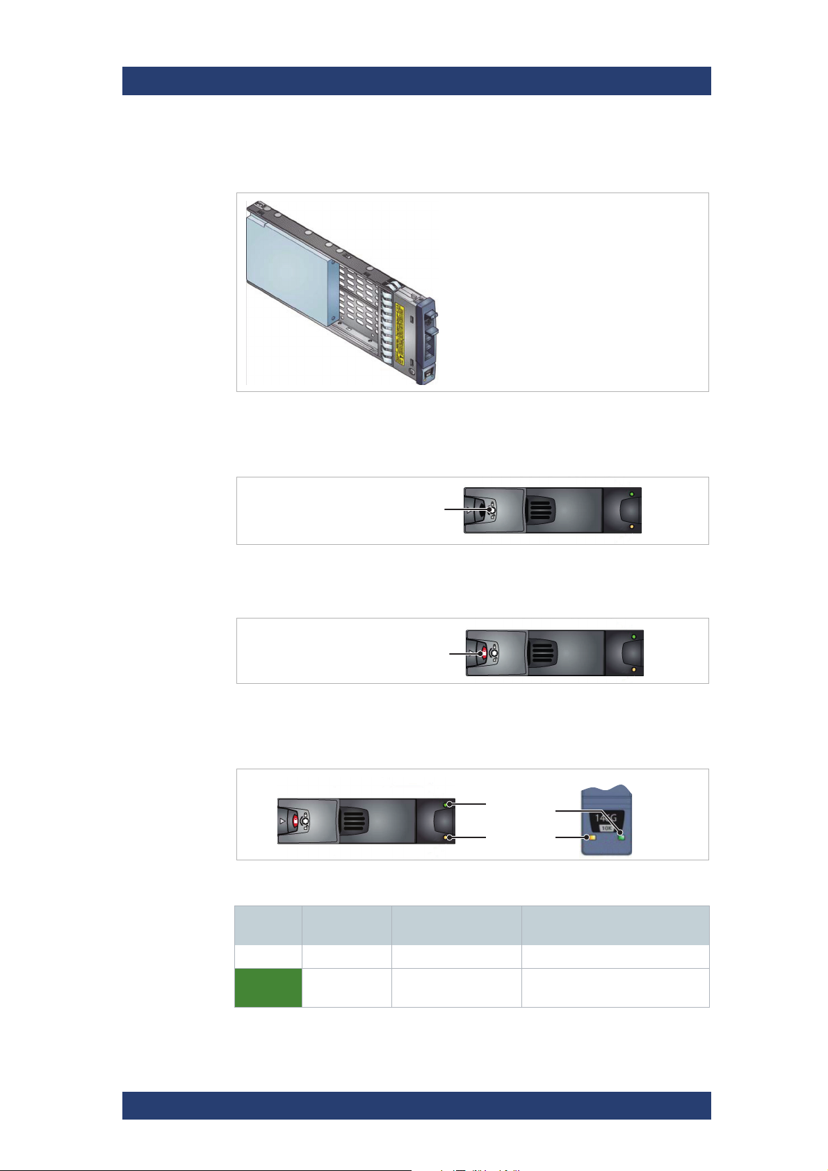
Product Description
Anti-tamper lock
Indicator aperture
HB
EB
Green
Amber
The Front of the System
In 2U24 enclosures a EB carrier is used. It houses a single 2.5 inch SAS or
SATA drive.
EB drive carrier (SAS Drive)
Anti-tamper Locks
The HB and the EB carrier provides anti-tamper locks.
SpycerNode
Anti tamper lock unlocked
When locked, the carrier cannot be removed from the enclosure. This will be
indicated by the indicator aperture.
Anti tamper lock locked / Indicator aperture
LEDs
The HB and EB drive carriers have a green and an amber LED.
HB and EB drive carrier LEDs
Green Amber Associated
operation panel
Off Off None No drive installed
On/
Flashing
Off None Drive installed and
Status
operational
26
User Manual | 2902.3266.02 - 10
SpycerNode
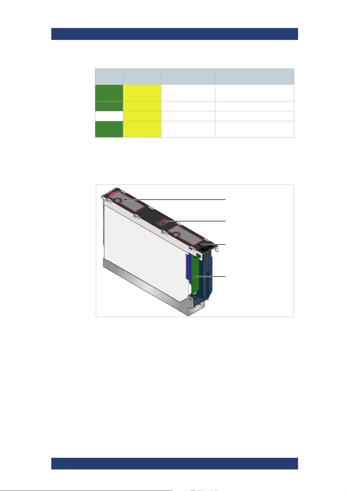
Slide latch
Latch button
Drive fault LED
Dongle
Product Description
The Front of the System
Green Amber Associated
operation panel
On Flash
1s on/1s off
On On Logical fault (amber) SES device fault bit set
Off On Module fault (amber) Power control circuit failure
On Flash
1s on/1s off
Logical fault (amber) RAID event indication
None SES device identify set
Status
Carriers (5U Enclosure)
In the 5U enclosures, each drive is housed in a carrier that enables secure
insertion of the drive into the drawer.
Disk drive in carrier
The following hard disk drives are supported:
● 3.5” 7200rpm SAS drive
Contact your storage vendor for details of other hard disk drives that are
available for use in the SpycerNode 5U storage system.
The following solid state drives are supported:
● 2.5” SAS solid state drive with 3.5” adapter
The drive carrier has a single amber LED which is lit when the drive has a
fault.
User Manual | 2902.3266.02 - 10
27
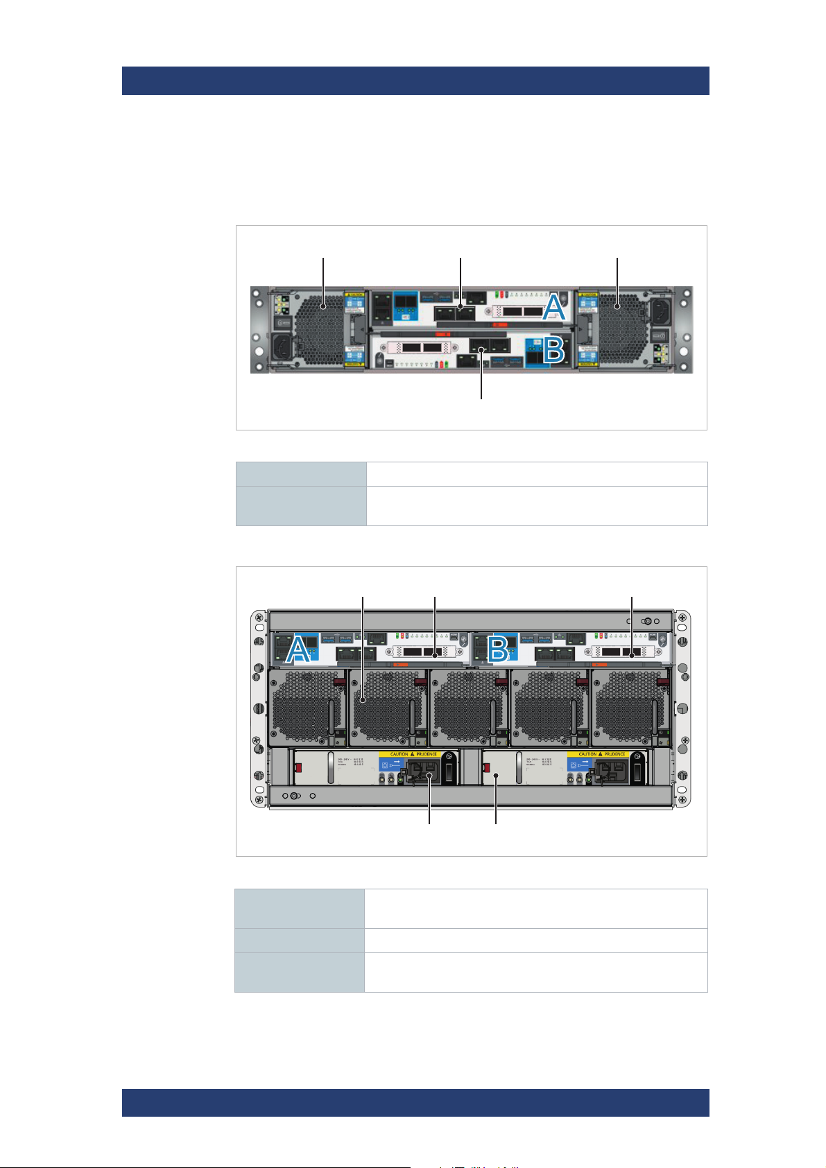
Product Description
Power cooling module
I/O module in slot A
I/O module in slot B
Power cooling module
Cooling module
Power supply unit
I/O module in slot A I/O module in slot B
The Rear of the System
The Rear of the System
The rear of the chassis provides access to the I/O modules and the (power)
cooling modules.
Back panel for 2U12 with 2x AP-LS I/O modules
I/O module (2x) For more information see chapter “I/O Modules” on page 29.
SpycerNode
Power cooling
module (2x)
For more information see chapter “Power Cooling Module
(2U Enclosures)” on page 33.
Back panel for 5U84
Cooling module (5x) For more information see chapter “Fan Cooling Modules (5U
Enclosure)” on page 34
28
I/O module (2x) For more information see chapter “I/O Modules” on page 29.
Power supply unit
(2x)
For more information see chapter “Power Supply Unit (5U
Enclosure)” on page 36.
User Manual | 2902.3266.02 - 10
SpycerNode
12 Gb/s SAS
connectors
USB
connectors
Ethernet
connector
HDMI
port
Serial
port
1 Gbit Ethernet
connectors
100 Gbit Ethernet
connectors
10 Gbit Ethernet connectors
Product Description
The Rear of the System
I/O Modules
A pair of I/O modules (of identical type) are provided in the enclosure so that
the system can operate in HA (high available) mode. Incoming data is
processed and eventually stored on the storage devices within the enclosure
or on expansion enclosures.
Data Integrity is provided by protection of all data buses with at least parity
protection, but more commonly error-correcting memory as provided on the
main DRAM.
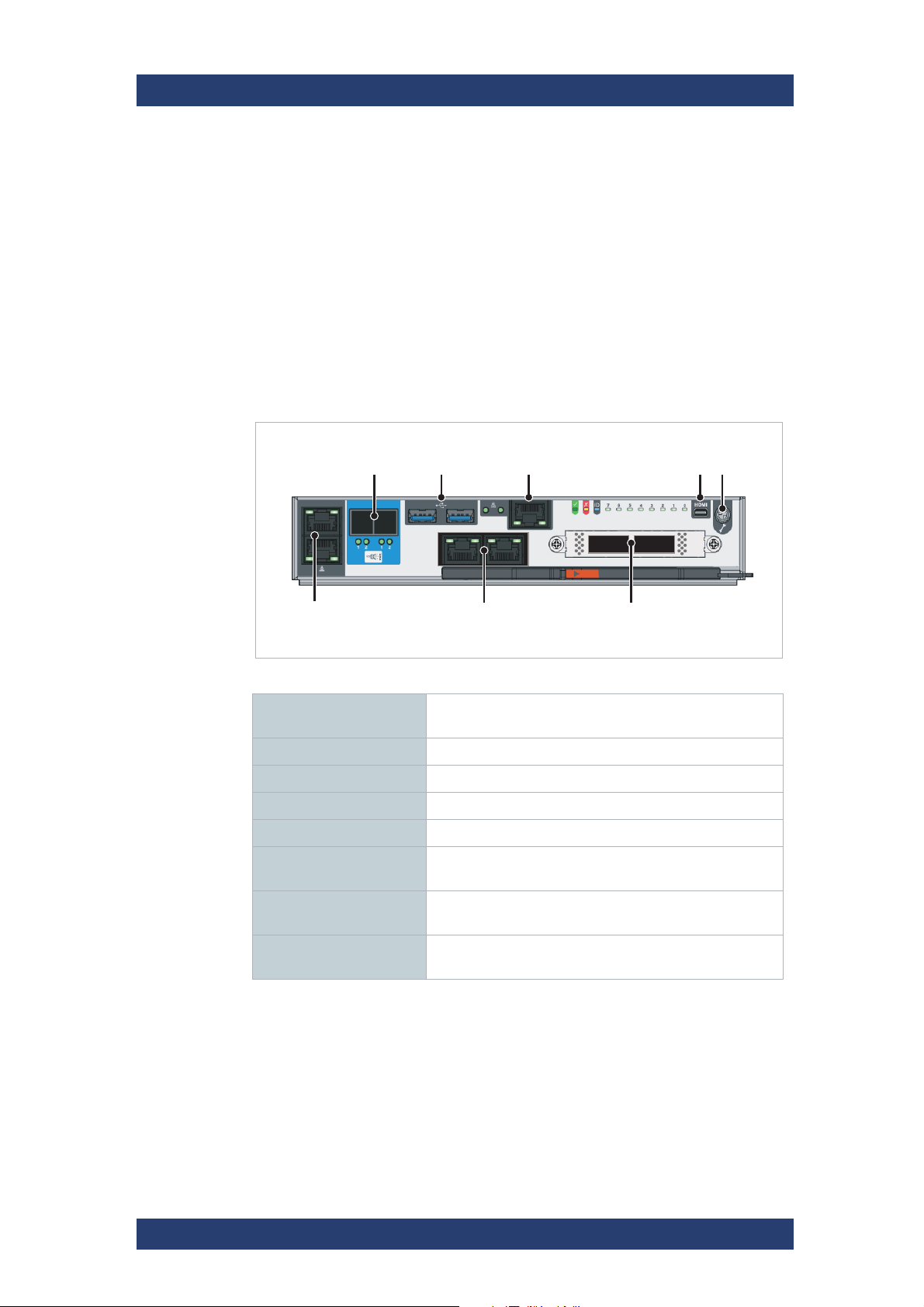
AP-LS I/O Module
AP-LS1 I/O module (12Gb/s)
12 Gb/s SAS
connectors
USB connectors For service purpose only.
Ethernet connector For internal purpose only.
Micro HDMI port For service purpose only.
Serial port For service purpose only.
100 Gbit Ethernet
connectors
10 Gbit Ethernet connectors
1 Gbit Ethernet connectors
Connection for storage extension (e.g. JBODs)
High speed storage network connections. For details
see chapter “Network Ports” on page 30.
LAN connection. For details see chapter “Network
Ports” on page 30.
LAN connection. For details see chapter “Network
Ports” on page 30.
For more information about the configuration see chapter “Initial Setup” on
page 60.
User Manual | 2902.3266.02 - 10
29

Product Description
enp1s0f1
enp1s0f2 ens1f0enp11s0f1
enp1s0f0
enp11s0f0 ens1f1
OK Fault ID Post
SAS activity
Ethernet status (1)
Ethernet
status (4)
Ethernet status (2)Ethernet status (3)
The Rear of the System
Network Ports
AP-LS1 I/O module (12Gb/s)
enp1s0f1 Recommended management port: IPMI configuration and moni-
enp1s0f0 LAN connection (1 Gbit)
SpycerNode
toring
Default configuration: DHCP
For internal purpose only.
enp1s0f2 LAN connection (1 Gbit)
Default configuration: Static IP (10.0.0.4)
enp11s0f0 LAN connection (10 Gbit)
enp11s0f1 LAN connection (10 Gbit)
ens1f0 High speed storage network connections (100 Gbit)
ens1f1 High speed storage network connections (100 Gbit)
LEDs
LEDs for AP-LS1 I/O module
30
OK/ Fault / IDFor more information see the following table.
SAS
activity
Steady green when there is a connection but no activity.
Flashing green when there is a connection and activity.
User Manual | 2902.3266.02 - 10
 Loading...