

Rohde&Schwarz R&S®SMW200A TETRA Release2 user manual User Manual

R&S®SMW-K68
TETRA Release 2
User Manual
(;ÙÒ:2)
1175681002
Version 17

This document describes the following software options:
●
R&S®SMW-K68 TETRA Release 2 (1413.4439.xx)
This manual describes firmware version FW 5.00.044.xx and later of the R&S®SMW200A.
© 2021 Rohde & Schwarz GmbH & Co. KG
Mühldorfstr. 15, 81671 München, Germany
Phone: +49 89 41 29 - 0
Email: info@rohde-schwarz.com
Internet: www.rohde-schwarz.com
Subject to change – data without tolerance limits is not binding.
R&S® is a registered trademark of Rohde & Schwarz GmbH & Co. KG.
Trade names are trademarks of the owners.
1175.6810.02 | Version 17 | R&S®SMW-K68
The following abbreviations are used throughout this manual: R&S®SMW200A is abbreviated as R&S SMW, R&S®WinIQSIM2TM is
abbreviated as R&S WinIQSIM2; the license types 02/03/07/11/13/16/12 are abbreviated as xx.

R&S®SMW-K68
1 Welcome to the TETRA2 digital standard............................................5
1.1 Accessing the TETRA dialog....................................................................................... 5
1.2 What's new.....................................................................................................................6
1.3 Documentation overview..............................................................................................6
1.3.1 Getting started manual....................................................................................................6
1.3.2 User manuals and help................................................................................................... 6
1.3.3 Tutorials...........................................................................................................................7
1.3.4 Service manual............................................................................................................... 7
1.3.5 Instrument security procedures.......................................................................................7
1.3.6 Printed safety instructions............................................................................................... 7
1.3.7 Data sheets and brochures............................................................................................. 7
Contents
Contents
1.3.8 Release notes and open source acknowledgment (OSA).............................................. 7
1.3.9 Application notes, application cards, white papers, etc...................................................8
1.4 Scope............................................................................................................................. 8
1.5 Notes on screenshots...................................................................................................8
2 Required options....................................................................................9
3 TETRA2 configuration and settings................................................... 10
3.1 General settings.......................................................................................................... 10
3.2 Trigger settings........................................................................................................... 15
3.3 Marker settings............................................................................................................19
3.4 Clock settings..............................................................................................................21
3.5 Local and global connectors settings.......................................................................23
3.6 Frame configuration settings.....................................................................................23
3.7 Burst editor..................................................................................................................23
3.8 BSCH / BNCH/T........................................................................................................... 28
3.8.1 TETRA frequency..........................................................................................................29
3.8.2 Contents settings.......................................................................................................... 31
3.8.3 Scrambling.................................................................................................................... 34
3.9 Filter / clipping settings..............................................................................................36
3.9.1 Filter settings.................................................................................................................36
3.9.2 Modulation settings....................................................................................................... 38
3User Manual 1175.6810.02 ─ 17

R&S®SMW-K68
3.9.3 Clipping settings............................................................................................................39
3.10 Power ramp control.................................................................................................... 41
3.10.1 Ramp control.................................................................................................................42
3.10.2 Slot attenuations........................................................................................................... 43
4 Remote control commands.................................................................45
4.1 General commands.....................................................................................................46
4.2 Power ramp commands..............................................................................................52
4.3 Slot configuration commands................................................................................... 54
4.4 BSCH / BNCH/T commands....................................................................................... 62
4.5 Filter/clipping commands...........................................................................................70
4.6 Trigger commands......................................................................................................73
4.7 Marker commands...................................................................................................... 78
Contents
4.8 Clock commands........................................................................................................ 81
List of commands................................................................................ 83
Index......................................................................................................86
4User Manual 1175.6810.02 ─ 17

R&S®SMW-K68
1 Welcome to the TETRA2 digital standard
Welcome to the TETRA2 digital standard
Accessing the TETRA dialog
The R&S SMW-K68 is a firmware application that adds functionality to generate signals in accordance with the standard Terrestrial Trunked Radio Release 2 (TETRA2).
The R&S SMW-K68 main features:
●
Generating of a signal in accordance with ETSI EN 300 392-2.
●
The TETRA frame (bit stream) is generated according to the selected burst type,
i.e. control burst (CB), normal burst (NB) or synchronization burst (SB).
●
The frames are generated for the uplink (mobile station [MS] transmitting) or the
downlink (base station [BS] transmitting).
●
The channel types AACH, BSCH, BNCH, TCH, STCH, SCH as well as the TETRA
Release 2 specific channels like SCH-Q, etc. are generated.
●
Channel coding including scrambling with system code, base color code, mobile
country code and mobile network code are performed for all channels.
●
Frame repetition can be selected via sequence length.
●
The T1 test signal is generated for the V+D (voice and data) test on MS and BS
DUTs.
●
Test channel types can be set for the downlink and for the uplink.
●
The bit stream can be generated either from pseudo-random sequences (CCITT
O.153) or from user-selectable sequences.
●
The R&S SMW calculates the appropriate TETRA2 T1, T2, T3 and T4 signal
according to the specification.
●
Additionally, user-defined test signal can be generated.
This user manual contains a description of the functionality that the application provides, including remote control operation.
All functions not discussed in this manual are the same as in the base unit and are
described in the R&S SMW user manual. The latest version is available at:
www.rohde-schwarz.com/manual/SMW200A
Installation
You can find detailed installation instructions in the delivery of the option or in the
R&S SMW service manual.
1.1 Accessing the TETRA dialog
To open the dialog with TETRA settings
► In the block diagram of the R&S SMW, select "Baseband > TETRA".
A dialog box opens that displays the provided general settings.
5User Manual 1175.6810.02 ─ 17

R&S®SMW-K68
1.2 What's new
1.3 Documentation overview
Welcome to the TETRA2 digital standard
Documentation overview
The signal generation is not started immediately. To start signal generation with the
default settings, select "State > On".
This manual describes firmware version FW 5.00.044.xx and later of the
R&S®SMW200A.
Compared to the previous version there are editorial changes only.
This section provides an overview of the R&S SMW user documentation. Unless specified otherwise, you find the documents on the R&S SMW product page at:
www.rohde-schwarz.com/manual/smw200a
1.3.1 Getting started manual
Introduces the R&S SMW and describes how to set up and start working with the product. Includes basic operations, typical measurement examples, and general information, e.g. safety instructions, etc. A printed version is delivered with the instrument.
1.3.2 User manuals and help
Separate manuals for the base unit and the software options are provided for download:
●
Base unit manual
Contains the description of all instrument modes and functions. It also provides an
introduction to remote control, a complete description of the remote control commands with programming examples, and information on maintenance, instrument
interfaces and error messages. Includes the contents of the getting started manual.
●
Software option manual
Contains the description of the specific functions of an option. Basic information on
operating the R&S SMW is not included.
The contents of the user manuals are available as help in the R&S SMW. The help
offers quick, context-sensitive access to the complete information for the base unit and
the software options.
All user manuals are also available for download or for immediate display on the Internet.
6User Manual 1175.6810.02 ─ 17

R&S®SMW-K68
1.3.3 Tutorials
1.3.4 Service manual
1.3.5 Instrument security procedures
Welcome to the TETRA2 digital standard
Documentation overview
The R&S SMW provides interactive examples and demonstrations on operating the
instrument in form of tutorials. A set of tutorials is available directly on the instrument.
Describes the performance test for checking compliance with rated specifications, firmware update, troubleshooting, adjustments, installing options and maintenance.
The service manual is available for registered users on the global Rohde & Schwarz
information system (GLORIS):
https://gloris.rohde-schwarz.com
Deals with security issues when working with the R&S SMW in secure areas. It is available for download on the Internet.
1.3.6 Printed safety instructions
Provides safety information in many languages. The printed document is delivered with
the product.
1.3.7 Data sheets and brochures
The data sheet contains the technical specifications of the R&S SMW. It also lists the
options and their order numbers and optional accessories.
The brochure provides an overview of the instrument and deals with the specific characteristics.
See www.rohde-schwarz.com/brochure-datasheet/smw200a
1.3.8 Release notes and open source acknowledgment (OSA)
The release notes list new features, improvements and known issues of the current
firmware version, and describe the firmware installation.
The open-source acknowledgment document provides verbatim license texts of the
used open source software.
See www.rohde-schwarz.com/firmware/smw200a
7User Manual 1175.6810.02 ─ 17

R&S®SMW-K68
1.3.9 Application notes, application cards, white papers, etc.
1.4 Scope
Welcome to the TETRA2 digital standard
Notes on screenshots
These documents deal with special applications or background information on particular topics.
See www.rohde-schwarz.com/application/smw200a and www.rohde-schwarz.com/
manual/smw200a
Tasks (in manual or remote operation) that are also performed in the base unit in the
same way are not described here.
In particular, it includes:
●
Managing settings and data lists, like saving and loading settings, creating and
accessing data lists, or accessing files in a particular directory.
●
Information on regular trigger, marker and clock signals and filter settings, if appropriate.
●
General instrument configuration, such as checking the system configuration, configuring networks and remote operation
●
Using the common status registers
For a description of such tasks, see the R&S SMW user manual.
1.5 Notes on screenshots
When describing the functions of the product, we use sample screenshots. These
screenshots are meant to illustrate as many as possible of the provided functions and
possible interdependencies between parameters. The shown values may not represent
realistic usage scenarios.
The screenshots usually show a fully equipped product, that is: with all options installed. Thus, some functions shown in the screenshots may not be available in your particular product configuration.
8User Manual 1175.6810.02 ─ 17

R&S®SMW-K68
2 Required options
Required options
The basic equipment layout for generating TETRA Release 2 signals includes the:
●
Standard or wideband Baseband Generator (R&S SMW-B10/-B9)
●
Baseband main module (R&S SMW-B13) or wideband baseband main module
(R&S SMW-B13XT)
●
Frequency option (e.g. R&S SMW-B1003)
●
Digital standard TETRA release 2 (R&S SMW-K68)
You can generate signals via play-back of waveform files at the signal generator. To
create the waveform file using R&S WinIQSIM2, you do not need a specific option.
To play back the waveform file at the signal generator, you have two options:
●
Install the R&S WinIQSIM2 option of the digital standard, e.g. R&S SMW-K255 for
playing LTE waveforms
●
If supported, install the real-time option of the digital standard, e.g. R&S SMW-K55
for playing LTE waveforms
For more information, see data sheet.
9User Manual 1175.6810.02 ─ 17

R&S®SMW-K68
3 TETRA2 configuration and settings
TETRA2 configuration and settings
General settings
Access:
► Select "Baseband > TETRA".
The remote commands required to define these settings are described in Chapter 4,
"Remote control commands", on page 45.
Contents
● General settings......................................................................................................10
● Trigger settings....................................................................................................... 15
● Marker settings........................................................................................................19
● Clock settings..........................................................................................................21
● Local and global connectors settings......................................................................23
● Frame configuration settings...................................................................................23
● Burst editor..............................................................................................................23
● BSCH / BNCH/T......................................................................................................28
● Filter / clipping settings............................................................................................36
● Power ramp control.................................................................................................41
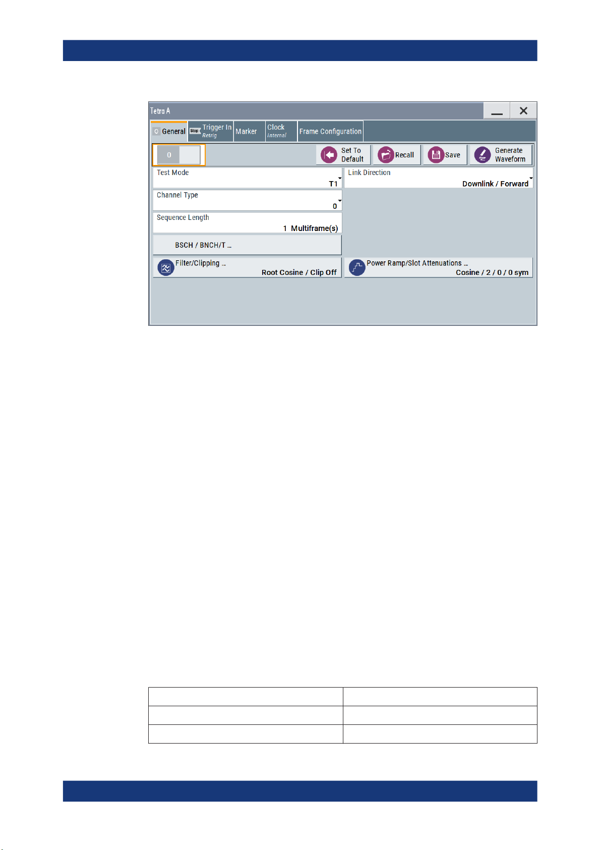
3.1 General settings
Access:
► Select "Baseband > TETRA > General".
This dialog provides access to the default, the "Save/Recall" settings and provides test
mode, channel type and link direction selection. The selected test mode and link direction determine the available parameters.
10User Manual 1175.6810.02 ─ 17
R&S®SMW-K68
TETRA2 configuration and settings
General settings
Settings:
State.............................................................................................................................. 11
Set to Default.................................................................................................................11
Save/Recall...................................................................................................................12
Generate Waveform......................................................................................................12
Test Mode......................................................................................................................12
Link Direction................................................................................................................ 13
Channel Type................................................................................................................14
Modulation Type............................................................................................................14
Downlink Burst Type..................................................................................................... 14
Sequence Length..........................................................................................................14
BSCH / BNCH/T............................................................................................................14
Filter / Clipping ............................................................................................................. 14
Power Ramp/Slot Attenuations..................................................................................... 14
State
Enables or disables the TETRA standard.
Activates the standard and deactivates all the other digital standards and digital modu-
lation modes in the same path.
Remote command:
[:SOURce<hw>]:BB:TETRa:STATe on page 50
Set to Default
Calls the default settings. The values of the main parameters are listed in the following
table.
Parameter Value
State Not affected by "Set to Default"
Test Mode T1
11User Manual 1175.6810.02 ─ 17

R&S®SMW-K68
TETRA2 configuration and settings
General settings
Parameter Value
Link Direction Downlink / Forward
Channel Type 0
Sequence Length 1 Multiframe
Power Ramp/Slot Attenuation cosine/ 2 / 0 / 0sym
Filter/Clipping Root Cosine / clipping Off
Trigger/Marker Auto/Int
Clock Internal
Remote command:
[:SOURce<hw>]:BB:TETRa:PRESet on page 48
Save/Recall
Accesses the "Save/Recall" dialog, that is the standard instrument function for saving
and recalling the complete dialog-related settings in a file. The provided navigation
possibilities in the dialog are self-explanatory.
The settings are saved in a file with predefined extension. You can define the filename
and the directory, in that you want to save the file.
See also, chapter "File and Data Management" in the R&S SMW user manual.
Remote command:
[:SOURce<hw>]:BB:TETRa:SETTing:LOAD on page 49
[:SOURce<hw>]:BB:TETRa:SETTing:STORe on page 50
[:SOURce<hw>]:BB:TETRa:SETTing:CATalog? on page 49
[:SOURce<hw>]:BB:TETRa:SETTing:DELete on page 49
Generate Waveform
With enabled signal generation, triggers the instrument to save the current settings of
an arbitrary waveform signal in a waveform file with predefined extension *.wv. You
can define the filename and the directory, in that you want to save the file.
Using the ARB modulation source, you can play back waveform files and/or process
the file to generate multi-carrier or multi-segment signals.
Remote command:
[:SOURce<hw>]:BB:TETRa:WAVeform:CREate on page 51
Test Mode
Selects the test mode.
Several settings depend on the selected test model.
12User Manual 1175.6810.02 ─ 17

R&S®SMW-K68
TETRA2 configuration and settings
General settings
"T1"
"T4"
"User Defined"
"T2"
"T3"
Remote command:
[:SOURce<hw>]:BB:TETRa:TMODe on page 51
Test signal T1 (TETRA wanted signal, phase modulated)
This test mode enables the generation of test signals that comply with
the TETRA air interface multiframe, frame and slot structure. The T1
test signal is generated according to EN 300 394-1V3.1.1 and is
intended to be the wanted signal transmitted by the test system during frames 1 to 17 in all receiver tests.
The signal is pi/4-DQPSK or pi/8-D8PSK modulated. Frame 18 transmits information for control purposes.
To enable configuration of the T1 signal for different receiver tests,
the channel type for the "T1" signal is user-selectable. Channel types
0 to 4, 21, 22 and 25 are available in the Downlink/Forward "Link
Direction" and channel types 7 to 11, 21, 23 and 24 for the Uplink/
Reverse direction.
The burst types Uplink/Reverse and Downlink/Forward are derived
from the channel types. The instrument generates the Tx data for
complete multiframes for the V+D service (voice and data). The contents of data fields are automatically inserted according to the burst
type. The control block (cb), blocks 1 + 2 (bk), the synchronization
block (sb) and the broadcast block (bb) for test signal T1 are generated according to the frame number and the channel type.
Test signal T4 (TETRA wanted signal, QAM modulated)
The test signal T4 comply with the TETRA air interface multiframe,
frame and slot structure. The T4 test signal is intended to be the wanted signal transmitted by the test system during frames 1 to 17 in all
receiver tests. Except form frame 18, the signal is 4-QAM, 16-QAM or
64-QAM modulated. Frame 18 transmits information for control purposes and is QAM and phase modulated (QAM + pi/4-DQPSK); the
frame is generated according to EN 300 394-1.
Enables the generation of user-defined test signal.
Test signal T2 (TETRA interfere)
The T2 test signal is phase or QAM modulated, depending on the
selected Modulation Type.
Test signal T3 (unmodulated interferer)
The T3 test signal is an unmodulated continuous sinusoidal out-ofband interfering signal.
Link Direction
Selects the transmission direction.
This parameter determines the available "Channel Types".
"Downlink/
Forward"
"Uplink/
Reverse"
Remote command:
[:SOURce<hw>]:BB:TETRa:LDIRection on page 48
The transmission direction selected is from the base station (BS) to
the terminal (MS). The signal corresponds to that of a BS.
The transmission direction selected is from MS to the BS. The signal
corresponds to that of a terminal.
13User Manual 1175.6810.02 ─ 17

R&S®SMW-K68
TETRA2 configuration and settings
General settings
Channel Type
(for "Test Model" set to T1 or T4)
Determines the channel type.
Remote command:
[:SOURce<hw>]:BB:TETRa:CTYPe on page 47
Modulation Type
(for "Test Model" set to "User Defined" or "T2")
Determines the modulation type, "Phase" or "QAM."
"Phase"
"QAM"
Remote command:
[:SOURce<hw>]:BB:TETRa:MTYPe on page 48
Downlink Burst Type
(in Downlink "Link Direction" and for "Test Model" set to "T2" or "User Defined")
Determines whether a discontinuous or continuous downlink burst type is used.
Remote command:
[:SOURce<hw>]:BB:TETRa:DBTYpe on page 47
The T2 test signal is a pi/4-DQPSK modulated continuous radio signal.
The T2 test signal is 4-QAM, 16-QAM or 64-QAM modulated and
spans a bandwidth of 25kHz, 50kHz, 100kHz or 150kHz.
Sequence Length
Selects the sequence length of the arbitrary waveform file in the number of multiframes. One multiframe is the minimum sequence length for a T1 signal.
Remote command:
[:SOURce<hw>]:BB:TETRa:SLENgth on page 50
BSCH / BNCH/T
Accesses the "BSCH / BNCH/T" dialog, used to configure the frequency settings, the
scrambling code and the content of the "Broadcast Synchronization Channel (BSCH)"
and the "Broadcast Network Channel (BNCH/T)", see Chapter 3.8, "BSCH / BNCH/T",
on page 28.
Filter / Clipping
Access to the dialog for setting baseband filtering, clipping and the sequence length of
the arbitrary waveform component, see Chapter 3.9, "Filter / clipping settings",
on page 36.
Power Ramp/Slot Attenuations
Calls the "Power Ramp Control" dialog. This dialog is used to set the power ramping
parameters and for setting values for the level attenuation in dB (see Chapter 3.10,
"Power ramp control", on page 41).
The currently selected ramp function and ramp time are displayed.
14User Manual 1175.6810.02 ─ 17
R&S®SMW-K68
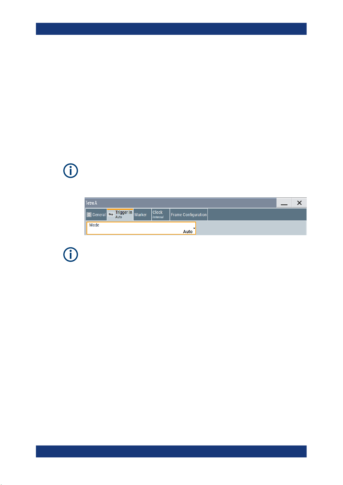
3.2 Trigger settings
TETRA2 configuration and settings
Trigger settings
Access:
► Select "Baseband > Tetra > Trigger In".
This tab provides access to the settings necessary to select and configure the trigger. It
includes the trigger mode, the trigger signal source, trigger delay, trigger suppression,
as well as to arm or trigger an internal trigger manually. The current signal generation
status is displayed in the header of the tab with information on the enabled trigger
mode. As in the "Marker" and "Clock" tabs, this tab provides also access to the settings
of the related connectors.
This section focuses on the available settings.
For information on how these settings affect the signal, refer to section "Basics on ..."
in the R&S SMW user manual.
Routing and enabling a trigger
The provided trigger signals are not dedicated to a particular connector. Trigger signals
can be mapped to one or more USER x or T/M connectors.
Use the Local and global connectors settings to configure the signal mapping, the
polarity, the trigger threshold and the input impedance of the input connectors.
To route and enable a trigger signal, perform the following general steps:
●
Define the signal source and the effect of a trigger event.
Select the "Trigger In > Mode" and "Trigger In > Source".
●
Define the connector where the selected signal is provided.
Use the "Global Connectors" settings.
Settings:
Trigger Settings Common to All Basebands................................................................. 16
└ Trigger Mode...................................................................................................16
└ Signal Duration Unit........................................................................................16
└ Trigger Signal Duration...................................................................................16
└ Running/Stopped............................................................................................ 17
└ Arm................................................................................................................. 17
└ Execute Trigger...............................................................................................17
└ Trigger Source................................................................................................ 17
15User Manual 1175.6810.02 ─ 17

R&S®SMW-K68
TETRA2 configuration and settings
Trigger settings
└ Sync. Output to External Trigger/Sync. Output to Trigger...............................18
└ External Trigger Inhibit....................................................................................18
Trigger Delay.................................................................................................................19
Trigger Settings Common to All Basebands
To enable simultaneous signal generation in all basebands, the R&S SMW couples the
trigger settings in the available basebands in any instrument's configuration involving
signal routing with signal addition. For example, in MIMO configuration, routing and
summing of basebands or of streams.
The icon
You can access and configure the common trigger source and trigger mode settings in
any of the basebands. An arm or a restart trigger event applies to all basebands, too.
You can still apply different delay to each of the triggers individually.
Trigger Mode ← Trigger Settings Common to All Basebands
Selects trigger mode, i.e. determines the effect of a trigger event on the signal generation.
For more information, refer to chapter "Basics" in the R&S SMW user manual.
●
"Auto"
The signal is generated continuously.
●
"Retrigger"
The signal is generated continuously. A trigger event (internal or external) causes a
restart.
●
"Armed Auto"
The signal is generated only when a trigger event occurs. Then the signal is generated continuously.
An "Arm" stops the signal generation. A subsequent trigger event (internal or external) causes a restart.
●
"Armed Retrigger"
The signal is generated only when a trigger event occurs. Then the signal is generated continuously. Every subsequent trigger event causes a restart.
An "Arm" stops signal generation. A subsequent trigger event (internal or external)
causes a restart.
●
"Single"
The signal is generated only when a trigger event occurs. Then the signal is generated once to the length specified at "Signal Duration".
Every subsequent trigger event (internal or external) causes a restart.
Remote command:
[:SOURce<hw>]:BB:TETRa:TRIGger:SEQuence on page 77
indicates that common trigger settings are applied.
Signal Duration Unit ← Trigger Settings Common to All Basebands
Defines the unit for describing the length of the signal sequence to be output in the
"Single" trigger mode.
Remote command:
[:SOURce<hw>]:BB:TETRa:TRIGger:SLUNit on page 75
Trigger Signal Duration ← Trigger Settings Common to All Basebands
Enters the length of the signal sequence to be output in the "Single" trigger mode.
16User Manual 1175.6810.02 ─ 17

R&S®SMW-K68
TETRA2 configuration and settings
Trigger settings
Use this parameter to output part of the signal deliberately, an exact sequence of the
signal, or a defined number of repetitions of the signal.
Remote command:
[:SOURce<hw>]:BB:TETRa:TRIGger:SLENgth on page 75
Running/Stopped ← Trigger Settings Common to All Basebands
With enabled modulation, displays the status of signal generation for all trigger modes.
●
"Running"
The signal is generated; a trigger was (internally or externally) initiated in triggered
mode.
●
"Stopped"
The signal is not generated and the instrument waits for a trigger event.
Remote command:
[:SOURce<hw>]:BB:TETRa:TRIGger:RMODe on page 75
Arm ← Trigger Settings Common to All Basebands
Stops the signal generation until subsequent trigger event occurs.
Remote command:
[:SOURce<hw>]:BB:TETRa:TRIGger:ARM:EXECute on page 74
Execute Trigger ← Trigger Settings Common to All Basebands
For internal trigger source, executes trigger manually.
Remote command:
[:SOURce<hw>]:BB:TETRa:TRIGger:EXECute on page 74
Trigger Source ← Trigger Settings Common to All Basebands
The following sources of the trigger signal are available:
●
"Internal"
The trigger event is executed manually by the "Execute Trigger".
●
"Internal (Baseband A/B)"
The trigger event is provided by the trigger signal from the other basebands.
If common trigger settings are applied, this trigger source is disabled.
●
"External Global Trigger"
The trigger event is the active edge of an external trigger signal provided and configured at the USER x connectors.
●
"External Local Trigger"
The trigger event is the active edge of an external trigger signal provided and configured at the local T/M/C connector.
With coupled trigger settings, the signal has to be provided at the T/M/C1/2/3 connectors.
●
"External Local Clock"
The trigger event is the active edge of an external local clock signal provided and
configured at the local T/M/C connector.
With coupled trigger settings, the signal has to be provided at the T/M/C1 connector.
Remote command:
[:SOURce<hw>]:BB:TETRa:TRIGger:SOURce on page 76
17User Manual 1175.6810.02 ─ 17

R&S®SMW-K68
TETRA2 configuration and settings
Trigger settings
Sync. Output to External Trigger/Sync. Output to Trigger ← Trigger Settings
Common to All Basebands
Enables signal output synchronous to the trigger event.
●
"On"
Corresponds to the default state of this parameter.
The signal calculation starts simultaneously with the trigger event. Because of the
processing time of the instrument, the first samples are cut off and no signal is output. After elapsing of the internal processing time, the output signal is synchronous
to the trigger event.
●
"Off"
The signal output begins after elapsing of the processing time. Signal output starts
with sample 0. The complete signal is output.
This mode is recommended for triggering of short signal sequences. Short sequences are sequences with signal duration comparable with the processing time of the
instrument.
Remote command:
[:SOURce<hw>]:BB:TETRa:TRIGger[:EXTernal<ch>]:SYNChronize:OUTPut
on page 74
External Trigger Inhibit ← Trigger Settings Common to All Basebands
Applies for external trigger signal or trigger signal from the other path.
Sets the duration with that any following trigger event is suppressed. In "Retrigger"
mode, for example, a new trigger event does not cause a restart of the signal generation until the specified inhibit duration does not expire.
For more information, see chapter "Basics" in the R&S SMW user manual.
18User Manual 1175.6810.02 ─ 17

R&S®SMW-K68
TETRA2 configuration and settings
Marker settings
Remote command:
[:SOURce<hw>]:BB:TETRa:TRIGger[:EXTernal]:INHibit on page 76
[:SOURce<hw>]:BB:TETRa:TRIGger:OBASeband:INHibit on page 75
Trigger Delay
Delays the trigger event of the signal from:
●
The external trigger source
●
The other path
●
The other basebands (internal trigger), if common trigger settings are used.
Use this setting to:
●
Synchronize the instrument with the device under test (DUT) or other external devices
●
Postpone the signal generation start in the basebands compared to each other
For more information, see chapter "Basics on ..." in the R&S SMW user manual.
Remote command:
[:SOURce<hw>]:BB:TETRa:TRIGger[:EXTernal]:DELay on page 76
[:SOURce<hw>]:BB:TETRa:TRIGger:OBASeband:DELay on page 74
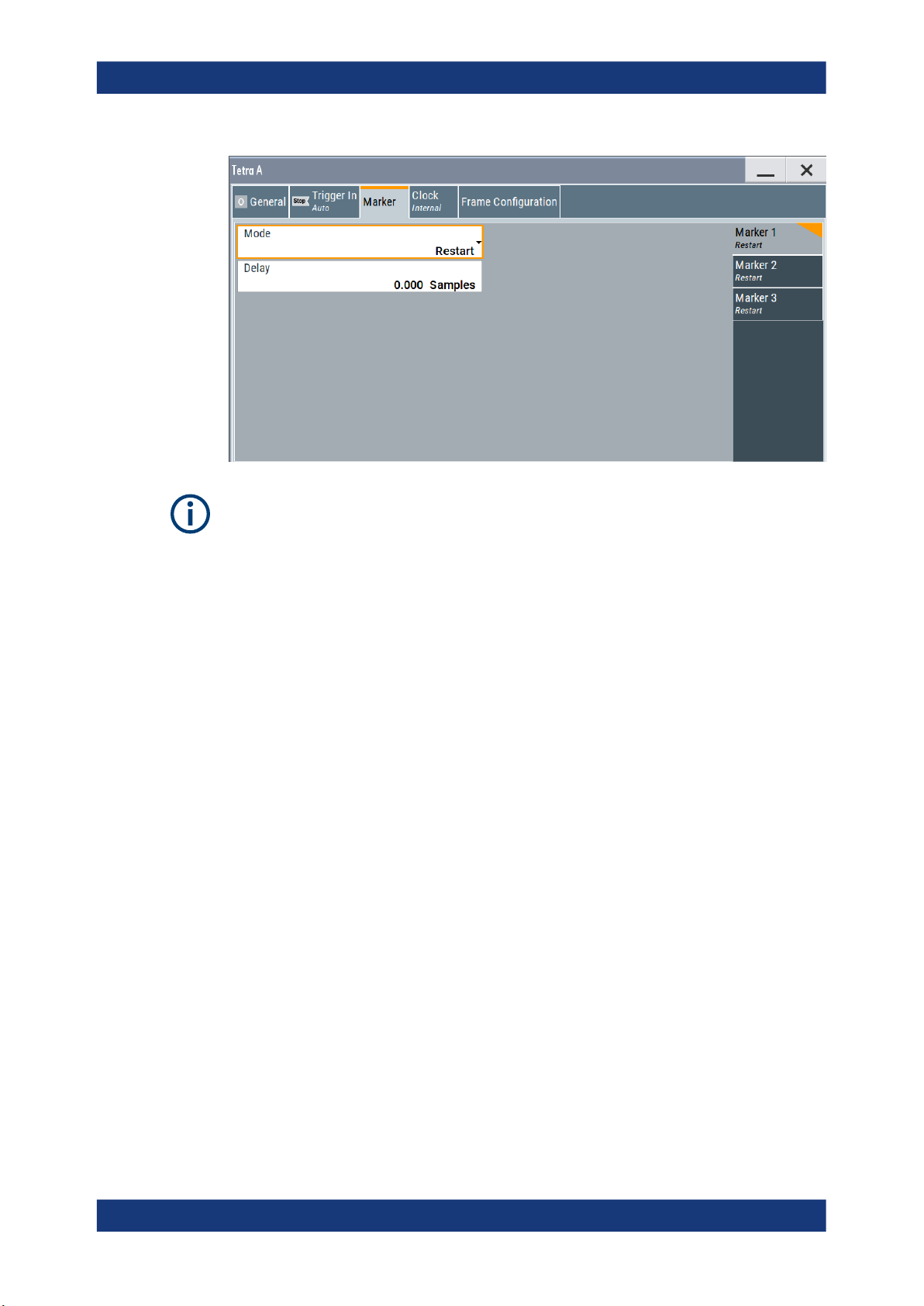
3.3 Marker settings
Access:
► Select "Baseband > Tetra > Marker".
This tab provides access to the settings necessary to select and configure the marker
output signal, like the marker mode or marker delay settings.
This section focuses on the available settings.
For information on how these settings affect the signal, refer to section "Basics on ..."
in the R&S SMW user manual.
19User Manual 1175.6810.02 ─ 17
R&S®SMW-K68
TETRA2 configuration and settings
Marker settings
Routing and enabling a marker
The provided marker signals are not dedicated to a particular connector. They can be
mapped to one or more USER x or T/M connectors.
To route and enable a marker signal, perform the following general steps:
●
Define the shape of the generated marker, i.e. select the "Marker > Mode".
●
Define the connector where the selected signal is provided.
Use the Local and global connectors settings.
Settings:
Marker Mode.................................................................................................................20
Marker x Delay..............................................................................................................21
Marker Mode
Marker configuration for up to 3 markers. The settings are used to select the marker
mode defining the shape and periodicity of the markers. The contents of the dialog
change with the selected marker mode.
"Restart"
"Slot Start "
"Frame Start"
"Multiframe Start"
"Hyperframe Start"
A marker signal is generated at the start of each ARB sequence.
A marker signal is generated at the start of each slot.
A marker signal is generated at the start of each frame.
A marker signal is generated at the start of each multiframe.
A marker signal is generated at the start of each hyperframe.
20User Manual 1175.6810.02 ─ 17
R&S®SMW-K68
TETRA2 configuration and settings
Clock settings
"Pulse"
Remote command:
[:SOURce<hw>]:BB:TETRa:TRIGger:OUTPut<ch>:PULSe:DIVider
on page 80
[:SOURce<hw>]:BB:TETRa:TRIGger:OUTPut<ch>:PULSe:FREQuency?
on page 81
"Pattern "
Remote command:
[:SOURce<hw>]:BB:TETRa:TRIGger:OUTPut<ch>:PATTern on page 80
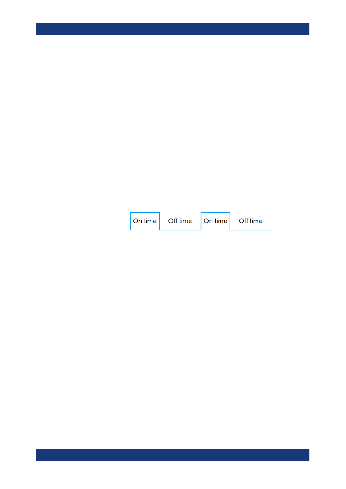
"ON/OFF
Period"
A regular marker signal is generated. The frequency is derived by
dividing the sample rate by the divider. The input box for the divider
opens when "Pulse" is selected, and the resulting pulse frequency is
displayed below it.
A marker signal that is defined by a bit pattern is generated. The pattern has a maximum length of 64 bits and is defined in an input field
which opens when pattern is selected.
A regular marker signal that is defined by an ON/OFF ratio is generated. A period lasts one ON and OFF cycle.
The "ON Time" and "OFF Time" are each expressed as a number of
samples and are set in an input field which opens when ON/OFF ratio
is selected.
Remote command:
[:SOURce<hw>]:BB:TETRa:TRIGger:OUTPut<ch>:ONTime on page 80
[:SOURce<hw>]:BB:TETRa:TRIGger:OUTPut<ch>:OFFTime on page 80
Remote command:
[:SOURce<hw>]:BB:TETRa:TRIGger:OUTPut<ch>:MODE on page 79
Marker x Delay
Delays the marker signal at the marker output relative to the signal generation start.
Variation of the parameter "Marker x Delay" causes signal recalculation.
Remote command:
[:SOURce<hw>]:BB:TETRa:TRIGger:OUTPut<ch>:DELay on page 78
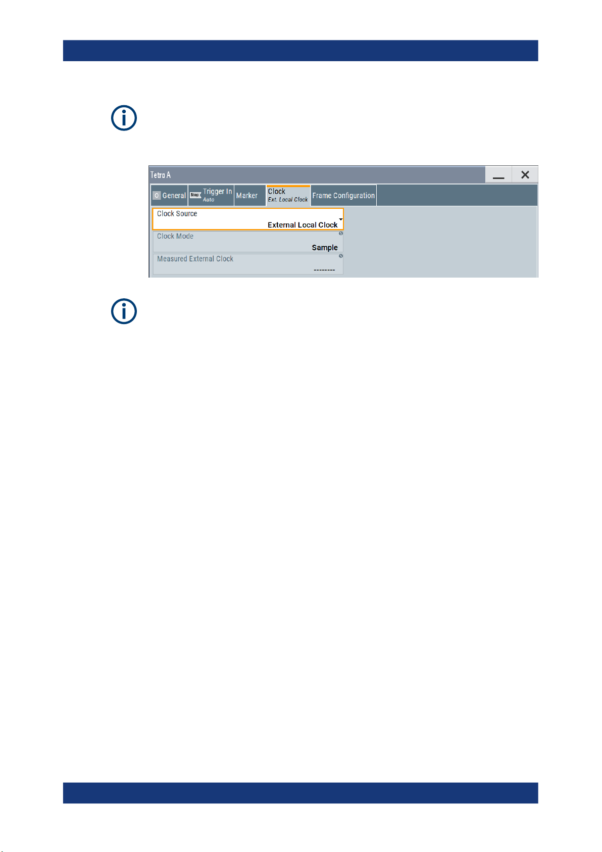
3.4 Clock settings
Access:
► Select "Baseband > Tetra > Clock".
This tab provides access to the settings necessary to select and configure the clock
signal, like the clock source and clock mode.
21User Manual 1175.6810.02 ─ 17
R&S®SMW-K68
TETRA2 configuration and settings
Clock settings
This section focuses on the available settings.
For information on how these settings affect the signal, refer to section "Basics on ..."
in the R&S SMW user manual.
Defining the clock
The provided clock signals are not dedicated to a particular connector. They can be
mapped to one or more USER x and T/M/C connectors.
Use the Local and global connectors settings to configure the signal mapping, the
polarity, the trigger threshold, and the input impedance of the input connectors.
To route and enable a trigger signal, perform the following general steps:
●
Define the signal source, that is select the "Clock > Source".
●
Define the connector where the selected signal is provided.
Use the Local and global connectors settings.
Settings:
Clock Source.................................................................................................................22
Clock Mode................................................................................................................... 22
Measured External Clock..............................................................................................23
Clock Source
Selects the clock source.
●
"Internal"
The instrument uses its internal clock reference.
●
"External Local Clock"
Option: R&S SMW-B10
The instrument expects an external clock reference at the local T/M/C connector.
Remote command:
[:SOURce<hw>]:BB:TETRa:CLOCk:SOURce on page 81
Clock Mode
Sets the type of externally supplied clock.
Remote command:
[:SOURce<hw>]:BB:TETRa:CLOCk:MODE on page 81
22User Manual 1175.6810.02 ─ 17
R&S®SMW-K68
3.5 Local and global connectors settings
TETRA2 configuration and settings
Burst editor
Measured External Clock
Provided for permanent monitoring of the enabled and externally supplied clock signal.
Remote command:
CLOCk:INPut:FREQuency?
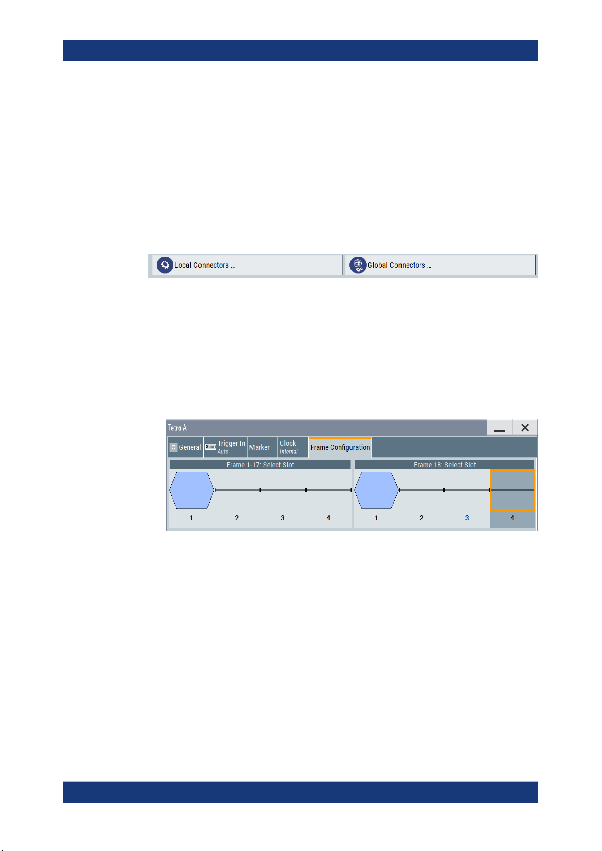
Each of the "Trigger In", "Marker" and "Clock" dialogs and the "Trigger Marker Clock"
dialog provides a quick access to the related connector settings.
See also chapter "Local and global connectors settings" in the user manual.
3.6 Frame configuration settings
Access:
1. Select "Baseband > Tetra > Frame Configuration".
The dialog displays the frames slots graphically.
2. Select the slot to for configuration.
The corresponding burst editor dialog opens, see Chapter 3.7, "Burst editor",
on page 23.
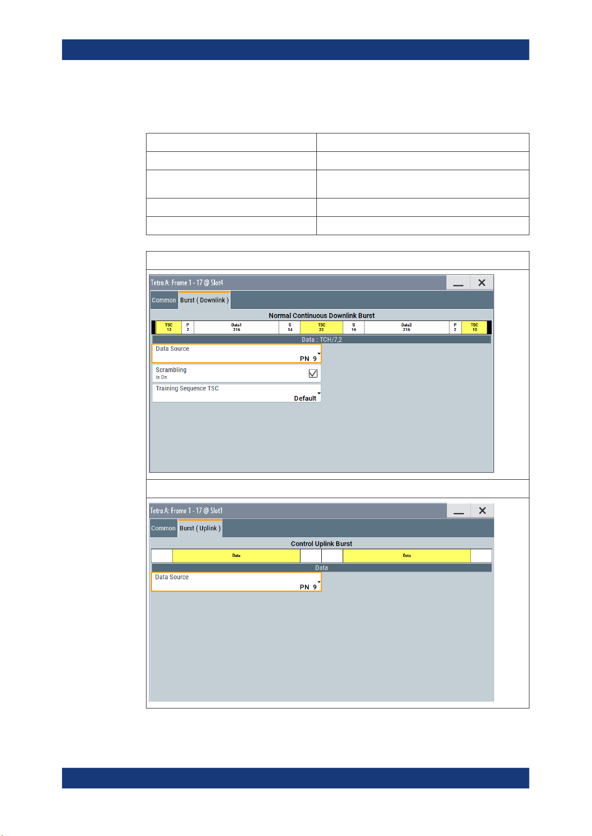
3.7 Burst editor
Access:
► Select "Frame Configuration > Frame: Select Slot > Frame".
23User Manual 1175.6810.02 ─ 17
R&S®SMW-K68
TETRA2 configuration and settings
Burst editor
At the top of the dialog, the structure of the current burst type for the selected slot is
displayed. Individual fields of the frame are color-coded:
Field Color
Data, Fixed, Mixed, Stealing white
White Training Sequences: TSC, ETSC,
SYNC
Tail, extended Tail green
Guard, extended Guard blue
normal burst:
yellow
control burst:
24User Manual 1175.6810.02 ─ 17

R&S®SMW-K68
TETRA2 configuration and settings
Burst editor
The rest of the dialog displays the data contained in fields predefined by the standard
for the current burst type. Data fields with variable content can be edited.
The following sections list all possible settings and displays for the various burst types.
If a setting applies only to a particular burst type, it is mentioned for the corresponding
parameter.
Settings:
Common........................................................................................................................25
└ T2 Burst Type..................................................................................................25
└ (Sub-) Slot Level............................................................................................. 25
└ (Sub-) Slot Attenuation....................................................................................25
└ Use Coded T1/T4 Data...................................................................................26
└ Logical Channel Type..................................................................................... 26
└ AACH-Q Mode................................................................................................26
└ Access-Assign PDU........................................................................................26
Burst (Downlink/Uplink).................................................................................................27
└ Data Source....................................................................................................27
└ Scrambling......................................................................................................28
└ Training Sequence..........................................................................................28
└ TSC User Defined...........................................................................................28
Common
Selects the common settings for the selected slot.
T2 Burst Type ← Common
Selects the burst type for "Test Mode T2".
Remote command:
[:SOURce<hw>]:BB:TETRa:SCONfiguration:SLOT<st>:LDIRection<ch>:
TBTYpe on page 54
(Sub-) Slot Level ← Common
Sets the level for the selected (sub-)slot.
Subslots are used by control bursts only.
"Off"
"Full"
"Attenuated"
Remote command:
[:SOURce<hw>]:BB:TETRa:SCONfiguration:TMODe<di>:SLOT<st>:
LDIRection<ch>:SLEVel on page 60 for "Slot Level"
[:SOURce<hw>]:BB:TETRa:SCONfiguration:TMODe<di>:SLOT<st>:
LDIRection<ch>:SSLevel on page 61 for "Sub-Slot Level".
Attenuation is maximum. The (sub-) slot is inactive.
The level corresponds to the level indicated in the display.
Level is reduced by the level attenuation set in "(Sub-)Slot Attenua-
tion".
(Sub-) Slot Attenuation ← Common
Selects the level attenuation for the "(Sub-)Slot Level" attenuated setting.
Subslots are used by control bursts only.
25User Manual 1175.6810.02 ─ 17

R&S®SMW-K68
TETRA2 configuration and settings
Burst editor
Use the "Power Ramp Control" > "Slot Attenuations" dialog to define four different values for level attenuation.
Remote command:
[:SOURce<hw>]:BB:TETRa:SCONfiguration:TMODe<di>:SLOT<st>:
LDIRection<ch>:BSATtenuation on page 56 for "Slot-Attenuation".
[:SOURce<hw>]:BB:TETRa:SCONfiguration:TMODe<di>:SLOT<st>:
LDIRection<ch>:SSATtenuation on page 56 for "Sub-Slot Attenuation".
Use Coded T1/T4 Data ← Common
Enables/disables auto coding of the data.
If enabled, the selection of the data source is disabled.
Remote command:
[:SOURce<hw>]:BB:TETRa:SCONfiguration:SLOT<st>:UBBNch on page 55
Logical Channel Type ← Common
Selects the logical channel type.
The available channels depend on the selected Test Mode and Link Direction.
Remote command:
[:SOURce<hw>]:BB:TETRa:SCONfiguration:TMODe<di>:SLOT<st>:
LDIRection<ch>:LCTYpe on page 58
AACH-Q Mode ← Common
(enabled for Frame 1- 17)
Sets the AACH-Q mode element that indicates whether the "Access-Assign PDU" fol-
lows in the AACH-Q.
The AACH-Q ("Access Assignment Channel, QAM") channel is present on all transmit-
ted downlink slots (except slots containing BLCH-Q). It is used to indicate on each
QAM physical channel the assignment of the uplink and downlink slots.
"AccessAssign PDU"
"Reserved Element"
Remote command:
[:SOURce<hw>]:BB:TETRa:SCONfiguration:TMODe<di>:SLOT<st>:
LDIRection<ch>:AMODe on page 55
Access-Assign PDU ← Common
(enabled for Frame 1- 17)
Enables configuration of the "Access-Assign PDU" content.
The value of the AACH-Q mode element is set to 0, i.e. contents of
"Access-Assign PDU" are present.
The "Access-Assign PDU" is used to convey information about the
downlink slot in which it appears and also the access rights for the
corresponding (same-numbered) uplink slot.
The fields of the "Access-Assign PDU" are defined with the corresponding parameters.
The value must be set to all zeros.
26User Manual 1175.6810.02 ─ 17

R&S®SMW-K68
TETRA2 configuration and settings
Burst editor
"Header"
Remote command:
[:SOURce<hw>]:BB:TETRa:SCONfiguration:TMODe<di>:SLOT<st>:
LDIRection<ch>:APHeader on page 56
"Field1"
Remote command:
[:SOURce<hw>]:BB:TETRa:SCONfiguration:TMODe<di>:SLOT<st>:
LDIRection<ch>:APF1 on page 55
"Field2"
Remote command:
[:SOURce<hw>]:BB:TETRa:SCONfiguration:TMODe<di>:SLOT<st>:
LDIRection<ch>:APF2 on page 56
Burst (Downlink/Uplink)
Selects the settings for the "Logical Channel Type" of the selected burst "Link Direc-
tion".
Data Source ← Burst (Downlink/Uplink)
Selects a data source for the "Data" field.
The data source for both channels can be defined separately, i.e. each (sub-)slot has
its own data source.
If a burst contains multiple "Data" fields, they are treated as a continuous field. For
instance, a pseudo-random sequence is continued without interruption from one "Data"
field to the next.
The following standard data sources are available:
●
"All 0, All 1"
An internally generated sequence containing 0 data or 1 data.
●
"PNxx"
An internally generated pseudo-random noise sequence.
●
"Pattern"
An internally generated sequence according to a bit pattern.
Use the "Pattern" box to define the bit pattern.
●
"Data List/Select DList"
A binary data from a data list, internally or externally generated.
Select "Select DList" to access the standard "Select List" dialog.
– Select the "Select Data List > navigate to the list file *.dm_iqd > Select" to
select an existing data list.
– Use the "New" and "Edit" functions to create internally new data list or to edit
an existing one.
– Use the standard "File Manager" function to transfer external data lists to the
instrument.
See also:
●
Section "Modulation Data" in the R&S SMW user manual.
●
Section "File and Data Management" in the R&S SMW user manual.
●
Section "Data List Editor" in the R&S SMW user manual
Sets the value for the information element Header.
Sets the value for the information element Field 1.
Sets the value for the information element "Field2".
27User Manual 1175.6810.02 ─ 17
 Loading...