

Rohde&Schwarz R&S®SMW200A Radar Echo Generation user manual User Manual

R&S®SMW-K78
Radar Echo Generation
User Manual
(;ÛÌÂ2)
1177625202
Version 14

This document describes the following software options:
●
R&S®SMW-78 Radar Echo Generation (1414.1833.02)
This manual describes firmware version FW 5.00.166.xx and later of the R&S®SMW200A.
© 2022 Rohde & Schwarz GmbH & Co. KG
Muehldorfstr. 15, 81671 Muenchen, Germany
Phone: +49 89 41 29 - 0
Email: info@rohde-schwarz.com
Internet: www.rohde-schwarz.com
Subject to change – data without tolerance limits is not binding.
R&S® is a registered trademark of Rohde & Schwarz GmbH & Co. KG.
Trade names are trademarks of the owners.
1177.6252.02 | Version 14 | R&S®SMW-K78
The following abbreviations are used throughout this manual: R&S®SMW200A is abbreviated as R&S SMW, R&S®FSW is abbreviated as R&S FSW, R&S®Pulse Sequencer is abbreviated as R&S Pulse Sequencer

R&S®SMW-K78
1 Welcome to the Radar Echo Generation option..................................5
1.1 Accessing the Radar Echo Generation dialog........................................................... 5
1.2 What's new.....................................................................................................................7
1.3 Documentation overview..............................................................................................7
1.3.1 Getting started manual....................................................................................................7
1.3.2 User manuals and help................................................................................................... 7
1.3.3 Tutorials...........................................................................................................................8
1.3.4 Service manual............................................................................................................... 8
1.3.5 Instrument security procedures.......................................................................................8
1.3.6 Printed safety instructions............................................................................................... 8
1.3.7 Data sheets and brochures............................................................................................. 8
Contents
Contents
1.3.8 Release notes and open source acknowledgment (OSA).............................................. 8
1.3.9 Application notes, application cards, white papers, etc...................................................9
1.4 Scope............................................................................................................................. 9
1.5 Notes on screenshots...................................................................................................9
2 About the Radar Echo Generation option......................................... 10
2.1 Required options and equipment.............................................................................. 10
2.2 The principle of echo generation with R&S SMW-K78.............................................11
2.3 Analyzer and receiver overload protection.............................................................. 12
2.4 Important parameters and interdependencies......................................................... 13
2.4.1 Simulated objects types................................................................................................ 14
2.4.2 Radar received power PRx calculation...........................................................................14
2.4.2.1 Calculating the REG input and output levels (RefLevel
2.4.2.2 Setting the REG input and output levels (RefLevel
2.4.3 Doppler frequency shift calculation............................................................................... 19
2.4.4 Delay calculation........................................................................................................... 20
Analyzer
and Level
Analyzer
and Level
R&S SMW
R&S SMW
)..........15
)................ 18
2.4.5 System latency calibration............................................................................................ 22
2.5 General recommendations.........................................................................................22
3 Radar echo generation configuration and settings.......................... 24
3.1 Radar Setup settings.................................................................................................. 24
3User Manual 1177.6252.02 ─ 14

R&S®SMW-K78
3.2 Overview test setup.................................................................................................... 30
3.3 Restart settings........................................................................................................... 31
3.4 Simulation Setup settings.......................................................................................... 33
3.5 Object configuration settings.................................................................................... 37
3.6 Radar cross-section RCS setup settings..................................................................44
3.7 Object preview settings..............................................................................................47
4 How to generate radar echo signals.................................................. 49
4.1 Connecting the RUT and the REG (conducted test)................................................ 50
4.2 Connecting the R&S FSW to the R&S SMW............................................................. 50
4.3 Using the reference frequency of the R&S FSW...................................................... 50
4.4 Configure the connection to the R&S FSW.............................................................. 51
4.5 Simulating six echoes................................................................................................ 55
Contents
4.6 Generating up to 24 echoes....................................................................................... 57
4.7 Deactivating subset of objects configured in one REG blocks..............................59
4.8 Estimating the system latency time roughly............................................................ 59
5 Remote-control commands.................................................................61
5.1 Programming example............................................................................................... 61
5.2 General commands.....................................................................................................64
5.3 Restart commands......................................................................................................67
5.4 Radar setup commands............................................................................................. 69
5.5 Simulation setup commands..................................................................................... 73
5.6 Object configuration commands............................................................................... 78
5.7 Preview diagram commands......................................................................................87
Glossary: Terms and abbreviations................................................... 88
Glossary: Specifications, references, documents with further infor-
mation................................................................................................... 90
List of commands................................................................................ 91
Index......................................................................................................93
4User Manual 1177.6252.02 ─ 14

R&S®SMW-K78
1 Welcome to the Radar Echo Generation
Welcome to the Radar Echo Generation option
Accessing the Radar Echo Generation dialog
option
The R&S SMW-K78 is a firmware application that adds functionality to generate a single or multiple radar echo signals for radar tests.
The R&S SMW-K78 features include:
●
Radar echo generation for any input in real time
●
Simulation of up to 12 independent virtual static or moving objects
●
160 MHz RF bandwidth throughout the entire frequency range up to 40 GHz
●
Excellent RF performance of signal generator and analyzer
●
Possibility to add interferers and noise
●
Internal generator solution, no need for external PC
●
Intuitive and easy to use graphical user interface
This user manual contains a description of the functionality that the application provides, including remote control operation.
All functions not discussed in this manual are the same as in the base unit and are
described in the R&S SMW user manual. The latest version is available at:
www.rohde-schwarz.com/manual/SMW200A
Installation
You can find detailed installation instructions in the delivery of the option or in the
R&S SMW service manual.
1.1 Accessing the Radar Echo Generation dialog
To open the dialog with Radar Echo Generation settings
1. In the block diagram of the R&S SMW, select "System Config > System Configuration".
5User Manual 1177.6252.02 ─ 14
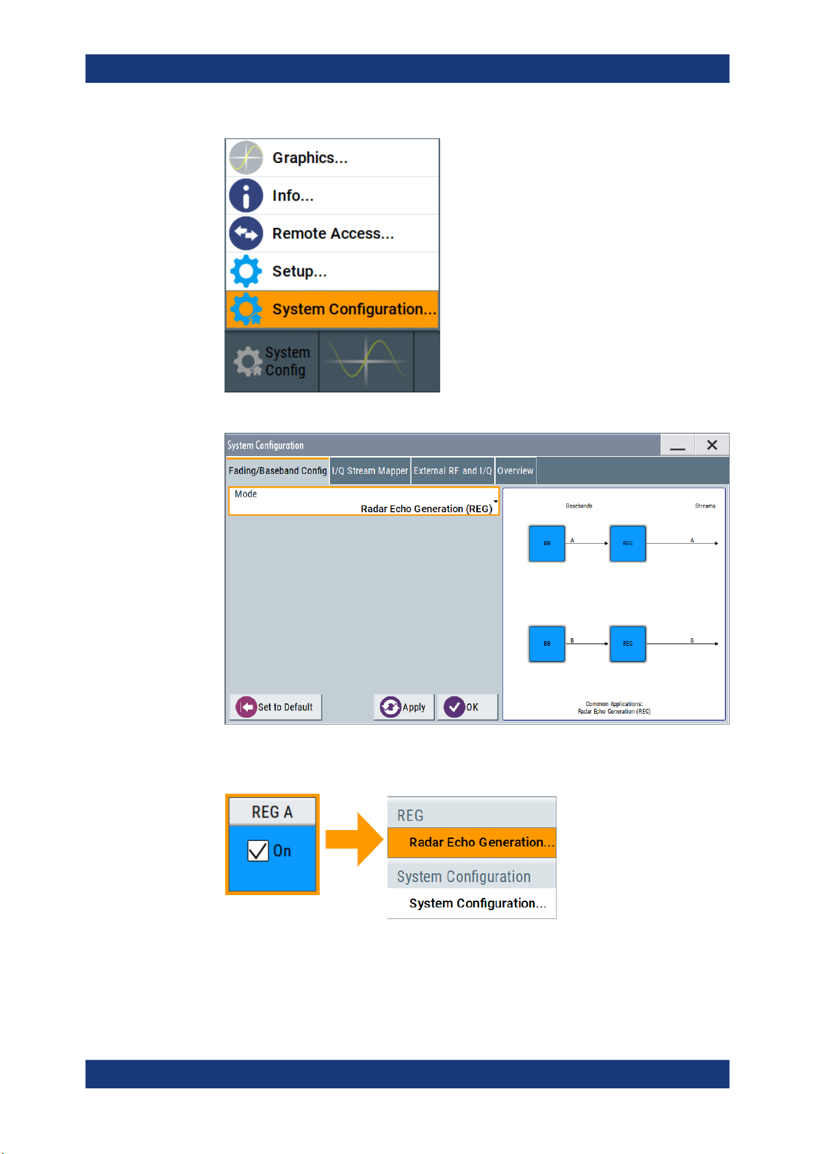
R&S®SMW-K78
Welcome to the Radar Echo Generation option
Accessing the Radar Echo Generation dialog
2. Select "Fading/Baseband Config > Mode > Radar Echo Generation (REG)".
3. Select "Apply" and confirm with "OK".
4. In the block diagram, select "REG > Radar Echo Generation".
A dialog box opens that displays the provided general settings.
The signal echo generation is not started immediately.
6User Manual 1177.6252.02 ─ 14

R&S®SMW-K78
1.2 What's new
1.3 Documentation overview
Welcome to the Radar Echo Generation option
Documentation overview
For more information, see Chapter 4, "How to generate radar echo signals",
on page 49.
This manual describes firmware version FW 5.00.166.xx and later of the
R&S®SMW200A.
Compared to the previous version there are editorial changes only.
This section provides an overview of the R&S SMW user documentation. Unless specified otherwise, you find the documents on the R&S SMW product page at:
www.rohde-schwarz.com/manual/smw200a
1.3.1 Getting started manual
Introduces the R&S SMW and describes how to set up and start working with the product. Includes basic operations, typical measurement examples, and general information, e.g. safety instructions, etc. A printed version is delivered with the instrument.
1.3.2 User manuals and help
Separate manuals for the base unit and the software options are provided for download:
●
Base unit manual
Contains the description of all instrument modes and functions. It also provides an
introduction to remote control, a complete description of the remote control commands with programming examples, and information on maintenance, instrument
interfaces and error messages. Includes the contents of the getting started manual.
●
Software option manual
Contains the description of the specific functions of an option. Basic information on
operating the R&S SMW is not included.
The contents of the user manuals are available as help in the R&S SMW. The help
offers quick, context-sensitive access to the complete information for the base unit and
the software options.
All user manuals are also available for download or for immediate display on the Internet.
7User Manual 1177.6252.02 ─ 14

R&S®SMW-K78
1.3.3 Tutorials
1.3.4 Service manual
1.3.5 Instrument security procedures
Welcome to the Radar Echo Generation option
Documentation overview
The R&S SMW provides interactive examples and demonstrations on operating the
instrument in form of tutorials. A set of tutorials is available directly on the instrument.
Describes the performance test for checking compliance with rated specifications, firmware update, troubleshooting, adjustments, installing options and maintenance.
The service manual is available for registered users on the global Rohde & Schwarz
information system (GLORIS):
https://gloris.rohde-schwarz.com
Deals with security issues when working with the R&S SMW in secure areas. It is available for download on the Internet.
1.3.6 Printed safety instructions
Provides safety information in many languages. The printed document is delivered with
the product.
1.3.7 Data sheets and brochures
The data sheet contains the technical specifications of the R&S SMW. It also lists the
options and their order numbers and optional accessories.
The brochure provides an overview of the instrument and deals with the specific characteristics.
See www.rohde-schwarz.com/brochure-datasheet/smw200a
1.3.8 Release notes and open source acknowledgment (OSA)
The release notes list new features, improvements and known issues of the current
firmware version, and describe the firmware installation.
The open-source acknowledgment document provides verbatim license texts of the
used open source software.
See www.rohde-schwarz.com/firmware/smw200a
8User Manual 1177.6252.02 ─ 14

R&S®SMW-K78
1.3.9 Application notes, application cards, white papers, etc.
1.4 Scope
Welcome to the Radar Echo Generation option
Notes on screenshots
These documents deal with special applications or background information on particular topics.
See www.rohde-schwarz.com/application/smw200a and www.rohde-schwarz.com/
manual/smw200a
Tasks (in manual or remote operation) that are also performed in the base unit in the
same way are not described here.
In particular, it includes:
●
Managing settings and data lists, like saving and loading settings, creating and
accessing data lists, or accessing files in a particular directory.
●
Information on regular trigger, marker and clock signals and filter settings, if appropriate.
●
General instrument configuration, such as checking the system configuration, configuring networks and remote operation
●
Using the common status registers
For a description of such tasks, see the R&S SMW user manual.
1.5 Notes on screenshots
When describing the functions of the product, we use sample screenshots. These
screenshots are meant to illustrate as many as possible of the provided functions and
possible interdependencies between parameters. The shown values may not represent
realistic usage scenarios.
The screenshots usually show a fully equipped product, that is: with all options installed. Thus, some functions shown in the screenshots may not be available in your particular product configuration.
9User Manual 1177.6252.02 ─ 14

R&S®SMW-K78
2 About the Radar Echo Generation option
2.1 Required options and equipment
About the Radar Echo Generation option
Required options and equipment
Testing of radar system with real targets can be a complex task, including expensive
and not reproducible field tests, or involving specially designed hardware. A novel
approach is to use standard test and measurement equipment instead, for example the
combination of the R&S SMW and the R&S FSW signal analyzer.
This description focuses on the functionality of the Radar Echo Generation
(R&S SMW-K78) option. It explains how the radar echo generator receives, manipulates, and retransmits radar waveforms to the radar under test.
R&S SMW
R&S SMW base unit equipped with:
●
Option baseband generator (R&S SMW-B10) and
Option baseband main module, with one/two I/Q paths (R&S SMW-B13/-B13T)
●
Frequency option (e.g. R&S SMW-B1003)
●
Option fading simulator (R&S SMW-B14)
●
Option Radar Echo Generation (R&S SMW-K78)
This configuration is sufficient for the generation of up to 6 echoes.
For more information, see data sheet.
R&S FSW
R&S®FSW signal and spectrum analyzer equipped with:
●
R&S®FSW-B17 digital baseband Interface
●
R&S®FSW-B160 160 MHz analysis bandwidth or any of the options R&S®FSWB80/-B320/-B500
For more information, see data sheet.
Required additional equipment and cables
As a rule, always use short cable of good quality:
●
One R&S®SMU-Z6 cable for connecting the digital I/Q interfaces of the R&S SMW
and the R&S FSW
●
2 BNC cables: for feeding the external reference frequency and the trigger signal
●
USB or LAN cable for connecting the R&S FSW and the R&S SMW
●
Depending on the test setup, one of the following:
– 2 RF cables (for conducted tests)
– Rx and Tx antennas (for over-the-air OTA tests)
10User Manual 1177.6252.02 ─ 14

R&S®SMW-K78
About the Radar Echo Generation option
The principle of echo generation with R&S
●
Optional, an external attenuator to protect the input stage of the R&S FSW
SMW-K78
2.2 The principle of echo generation with R&S SMW-K78
If equipped with the Radar Echo Generation (REG) option, the R&S SMW can work as
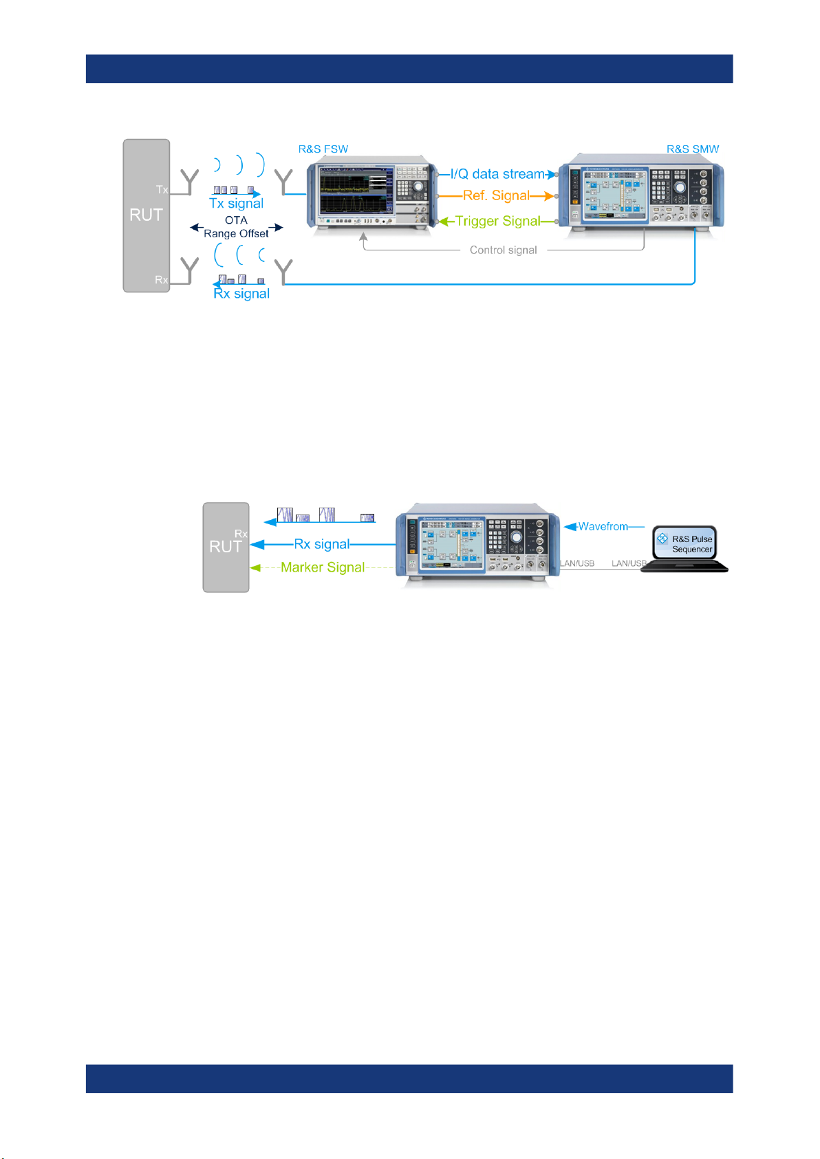
an echo generator together with the R&S FSW signal analyzer. An example of this solution is the test setup shown on Figure 2-1. The figure illustrates the radar echo generation with real radar signal as a principle.
Figure 2-1: Radar echo generation with R&S FSW, R&S SMW, and real radar signal (conducted test)
RUT = Radar under test
Tx signal = Transmitted (original) radar signal
Rx signal = Modified signal, fed back to the radar
I/Q data stream = Digital baseband data stream
Ref. Signal = 10 MHz common reference frequency signal to synchronize the R&S SMW to the R&S
FSW
Trigger Signal = Required to estimate the system latency of the system (blind zone (BZ))
Control signal = USB (or LAN) connection for remote control of the analyzer from the R&S SMW
The R&S FSW acts as a downconverter. It captures the transmitted analog radar signal
from the RUT (Tx signal) and converts it to a digital baseband signal. The R&S FSW
provides the digital signal via the digital I/Q interface to the R&S SMW. The R&S SMW
processes the received original signal (Tx signal), but changes the signal according to
the individual objects. The R&S SMW simulates range by delaying the received radar
signal. It simulates velocity by adding Doppler frequency shifts to the original signal
and radar cross sections (RCS) by attenuating the signal. The modified signal (Rx signal) is up-converted and fed back to the radar receiver [3].
The combination of the R&S FSW and the R&S SMW equipped with the option
R&S SMW-K78 is commonly referred as radar echo generator (REG).
In the test setup on Figure 2-1, there is a cable connection between the RUT and the
measurement equipment. Throughout this description, this setup is referred as a con-
ducted test. The RUT and the REG can also be located several meters away from
each other. To transmit and receive the signal, both the RUT and the REG are equipped with transmit and receive antennas. An example of this setup is illustrated on Fig-
ure 2-2. This kind of setup is referred as an over-the-air (OTA) test, where the dis-
tance between the RUT and the REG is referred as OTA distance.
11User Manual 1177.6252.02 ─ 14
R&S®SMW-K78
About the Radar Echo Generation option
Analyzer and receiver overload protection
Figure 2-2: Radar echo generation with real radar signal (over-the-air tests)
OTA = Over-the-air
OTA Range Offset = Distance between the RUT and the REG antennas
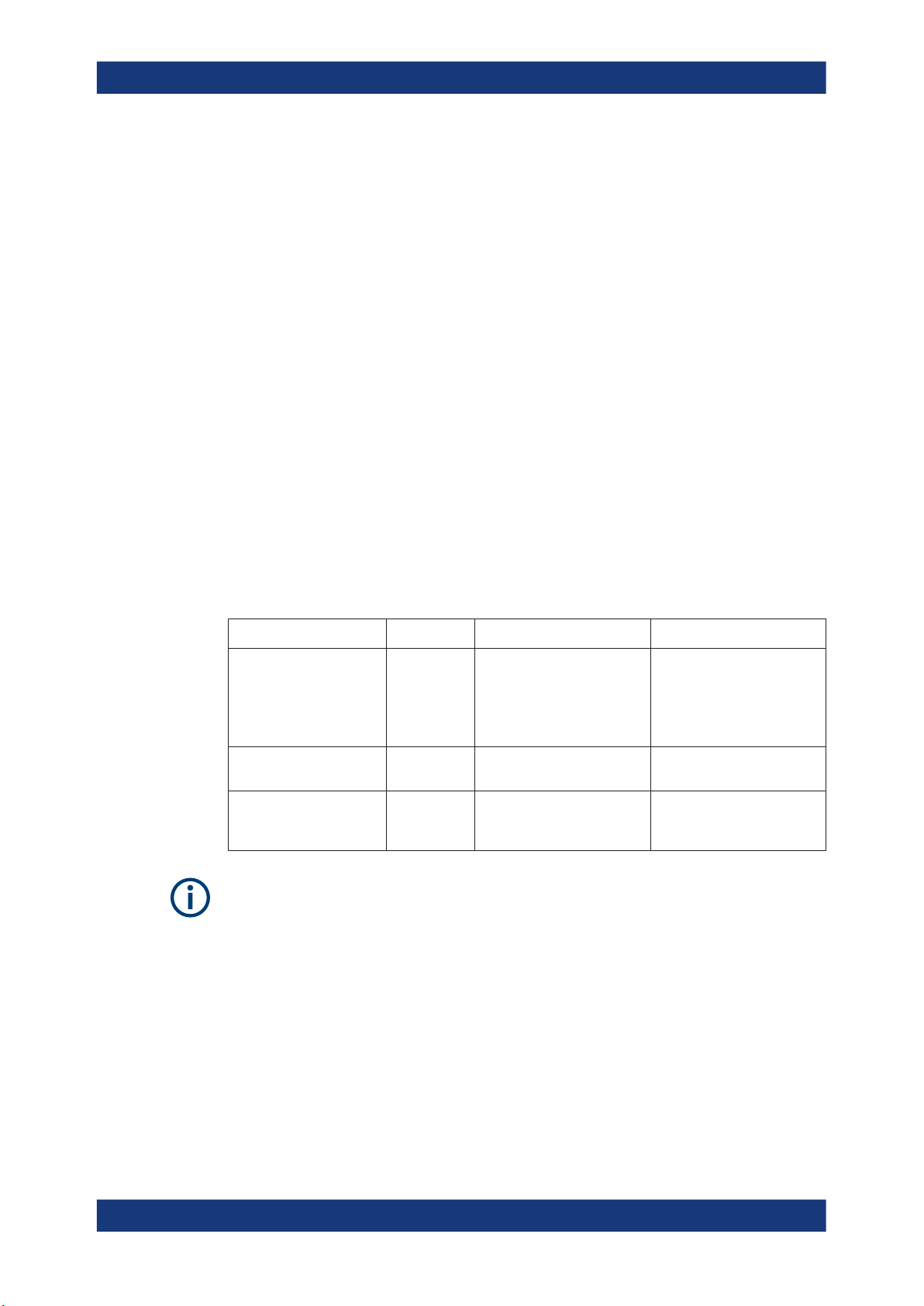
Alternatively to the two previous examples, the radar signals can be created internally
in the R&S SMW. The R&S SMW can play waveforms created with the R&S Pulse
Sequencer software or custom waveforms, that are loaded in the ARB generator. In
this case, a standalone R&S SMW is sufficient, for example for radar receiver tests
(see Figure 2-3). The characteristics of the objects can be imposed on the original signal in the same way as in the tests with real radar signal.
Figure 2-3: Radar echo generation with R&S SMW and ARB-based radar signals created by R&S
RUT = Radar under test
Rx signal = Modified test signal, transmitted to the radar
Pulse Sequencer
One of the advantages of this solution is the fact, that it is independent of the transmitter and the Tx signal of the radar system.
See:
●
Chapter 4, "How to generate radar echo signals", on page 49 for step-by-step
instructions.
●
Chapter 3, "Radar echo generation configuration and settings", on page 24 for
description of the related settings.
2.3 Analyzer and receiver overload protection
Follow the following general precautions:
●
NOTICE Risk of overloading
Signal strength outside the permissible input ranges may overload and damage the
signal analyzer R&S FSW and the radar receiver.
Always check the specifications for permissible input ranges.
12User Manual 1177.6252.02 ─ 14
R&S®SMW-K78
2.4 Important parameters and interdependencies
About the Radar Echo Generation option
Important parameters and interdependencies
Connect an external attenuator to protect the input stage of the analyzer.
●
Observe the theoretical dynamic power range of the scenario before activating the
REG.
(see "Ext. Attenuator (Analyzer)" on page 29)
●
To protect the radar inputs from overloading, limit the output power at the RF outputs of the R&S SMW.
Set the parameter "RF A or RF B > RF Level > Level > Limit" to the maximum
allowed receive power at the radar input.
For more information, see:
●
The R&S SMW user manual
●
The documentation of the radar under test (RUT)
●
The R&S FSW user manual [4].
This section is an overview of most important parameters of the radar echo generator
and the cross-reference between them. The section provides explanation of the used
equations and the calculation principles, together with information on the related settings.
Radar parameter Designation R&S SMW simulates it as Formula
Radar cross section (RCS)
Range R Signal delay Chapter 2.4.4, "Delay calcula-
Object velocity v Doppler frequency shift Chapter 2.4.3, "Doppler fre-
σ
Level attenuation "Radar equation"
on page 15
Chapter 2.4.2, "Radar
received power PRx calcula-
tion", on page 14
tion", on page 20
quency shift calculation",
on page 19
Background knowledge on radar principles, radar testing, and common terms in the
context of the radar systems is assumed.
For related information, see:
●
White Paper 1MA239: "Radar Waveforms for A&D and Automotive Radar" for an
overview of the radar waveforms
●
Application note 1MA256: "Real-time Radar Target Generation" for information on
radar testing
●
Application note 1MA127: "Introduction to Radar System and Component Tests" for
an overview of the radar measurements
13User Manual 1177.6252.02 ─ 14
R&S®SMW-K78
2.4.1 Simulated objects types
About the Radar Echo Generation option
Important parameters and interdependencies
The R&S SMW equipped with one Radar Echo Generation option can generate the
echo signal of up to 12 independent static or moving objects. In context of this firmware, a static object is an object with a zero object velocity. Static objects are placed
at a user-defined distance (range) from the radar.
A moving object is an object that approaches to or moves away from the radar with a
constant user-defined velocity (i.e. the acceleration is zero). The Doppler frequency
shift is a positive or negative value to indicate the direction of the movement. Different
spectral components are applyed with different doppler shifts. The object can move
back and forth between two user-defined positions (start range and end range). Its trajectory is a straight radial line leading out of the radar antennas.
A static + moving object is an artificial object, provided to simulate the combination of
constant range and positive velocity.
The objects are placed on a plain area. Elevation (altitude) and angle information is not
required. An isotropic antenna is assumed so that enabled objects are always visible.
2.4.2 Radar received power PRx calculation
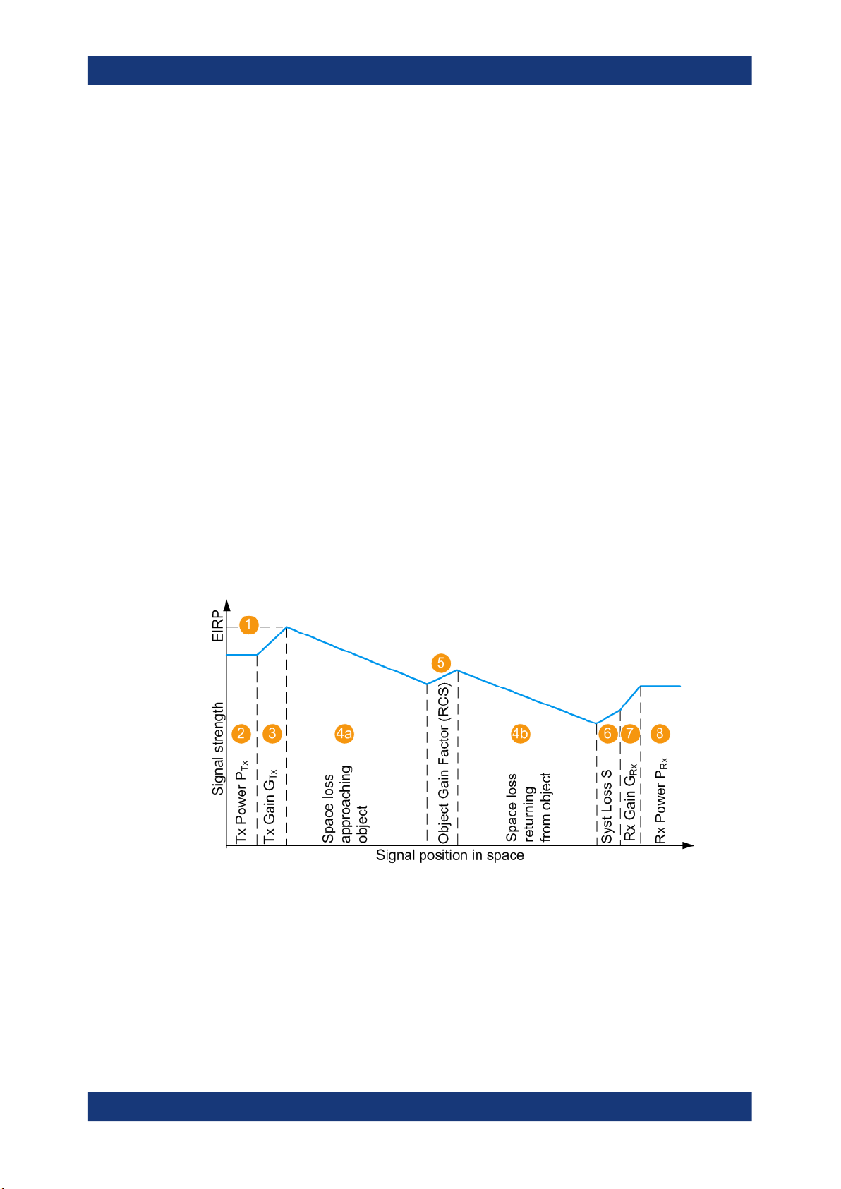
In the radar theory, the power returned to the radar PRx is given by the radar equation.
The illustration on Figure 2-4 shows the influence of the radar parameters on the radar
received power PRx.
Figure 2-4: Variation of the signal strength
1 = Equivalent isotopically radiated power (EIRP) of the radar; if GTx = 0 dBi, EIRP = P
2,3,7 = Radar parameters, see Radar under test (RUT) settings
4a,4b = Signal attenuation, simulated by the selected (Start) Range and End Range
5 = Radar cross-section (RCS), see Radar cross-section RCS setup settings
6 = Gain to compensate for cable loss (see "System Loss" on page 28)
2 to 7 = Configurable values
8 = Power of the Rx signal returned to the radar antenna PRx, calculated according to Radar equation
Tx
14User Manual 1177.6252.02 ─ 14

R&S®SMW-K78
About the Radar Echo Generation option
Important parameters and interdependencies
Radar equation
The power of the signal Rx returned to the radar antenna PRx is calculated as follows:
PRx [dBm] =
= PTx + GTx + GRx + S + σj + 20*log10(c0) - 20*log10(f) - 40*log10(Rj) - 30*log10(4π)
Where:
●
PRx is the power of the whole scenario, calculated as the sum of the P
P
is the calculated Rx power per object j
Rx,j
●
PTx is the radar transmitter power
values;
Rx,j
(see "Radar under test (RUT) settings" on page 28)
●
GTx and GRx are the antenna gains of the transmitting and the receiving antennas
of the RUT
(see "Radar under test (RUT) settings" on page 28 and "OTA tests settings"
on page 27)
●
S is the system loss
(see "OTA tests settings" on page 27)
●
σj is the radar cross section (RCS), or scattering coefficient of the object
(see Chapter 3.6, "Radar cross-section RCS setup settings", on page 44)
●
Rj is the range
(see "(Start) Range" on page 40 and "End Range" on page 40)
●
f is the dedicated frequency
(see "Dedicated Frequency" on page 36)
●
c0 ≈ 3*108 m/s is the speed of light
The resulting P
[dB] for the start and end range of each object is displayed with the
Rx,j
parameters:
●
Radar Rx Power (Start)
●
Radar Rx Power (End)
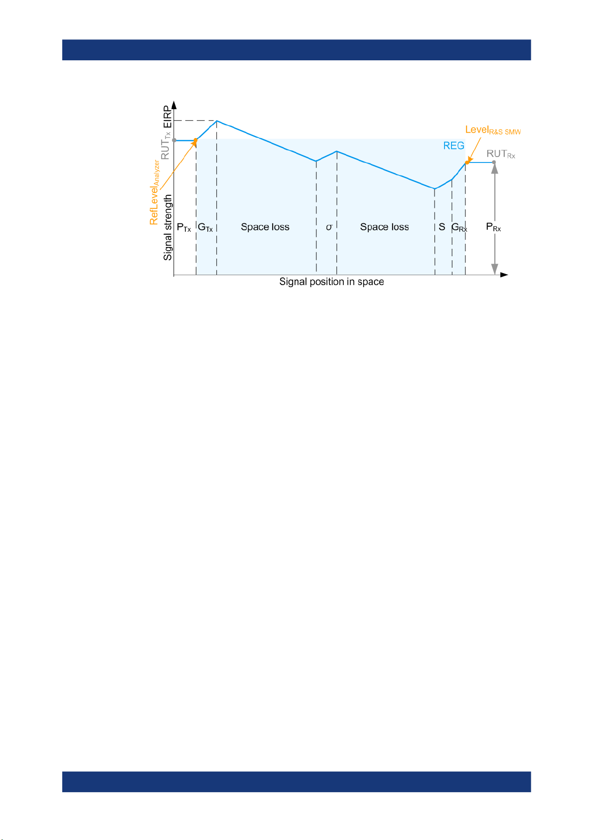
2.4.2.1 Calculating the REG input and output levels (RefLevel
Figure 2-4 illustrates the theoretical PRx calculation. When you generate radar echo
signal with the REG, the output level at the R&S SMW RF output is set so that the RUT
receives the power PRx, as it is calculated with the radar equation.
The illustration on Figure 2-5 resembles the same information as Figure 2-4, but it also
depicts the level at the REG input and output. The illustration assumes the case,
where:
●
The Tx output of the RUT is connected over cable to the input of the analyzer
●
The RF output of the R&S SMW is connected over cable to the Rx input of the RUT
The following applies:
●
The signal at the REG input is RefLevel
●
The signal at the REG output is Level
R&S SMW
Analyzer
= P
= P
Tx
Rx
Analyzer
and Level
R&S SMW
)
15User Manual 1177.6252.02 ─ 14
R&S®SMW-K78
About the Radar Echo Generation option
Important parameters and interdependencies
Figure 2-5: P_Rx calculation (simplified representation, "Ext. Attenuator A = 0 dB", "Test Setup =
EIRP, PTx, GTx,
G
Rx
Space loss = Signal attenuation, simulated by the selected "Range"
σ
S = Gain to compensate for cable loss
P
Rx
RefLevel
Level
R&S SMW
RUT
Tx
RUT
Rx
Analyzer
Conducted")
= Radar parameters
= Radar cross-section (RCS)
= Power of the Rx signal returned to the radar antenna, calculated according to Radar
equation
= Signal input level at the analyzer; if "Ext. Attenuator A = 0 dB", RefLevel
= Signal level at the REG output; if "Test Setup = Conducted", Level
= PTx is the signal level at the RUT output
= PRx is the signal level at the RUT input; PRx ≤ P
parameter "RF A or RF B > RF Level > Level > Limit" (see Chapter 2.3, "Analyzer and
receiver overload protection", on page 12)
Rx max
, where P
Rx max
Analyzer
= P
R&S SMW
is the set with the
= P
Rx
Tx
In practice, the RUT output is not directly connected to the REG input. The signal level
at the R&S SMW RF outputs is configured in the way that the power level received by
the RUT is the calculated PRx of the whole scenario. Connected external attenuator,
antenna gains of the Rx and Tx antennas connected to the measurement equipment,
distance between the antennas are considered automatically.
All these parameters are considered by the level settings in the signal analyzer and the
output level of the R&S SMW. Figure 2-6 and Figure 2-7 illustrate this principle.
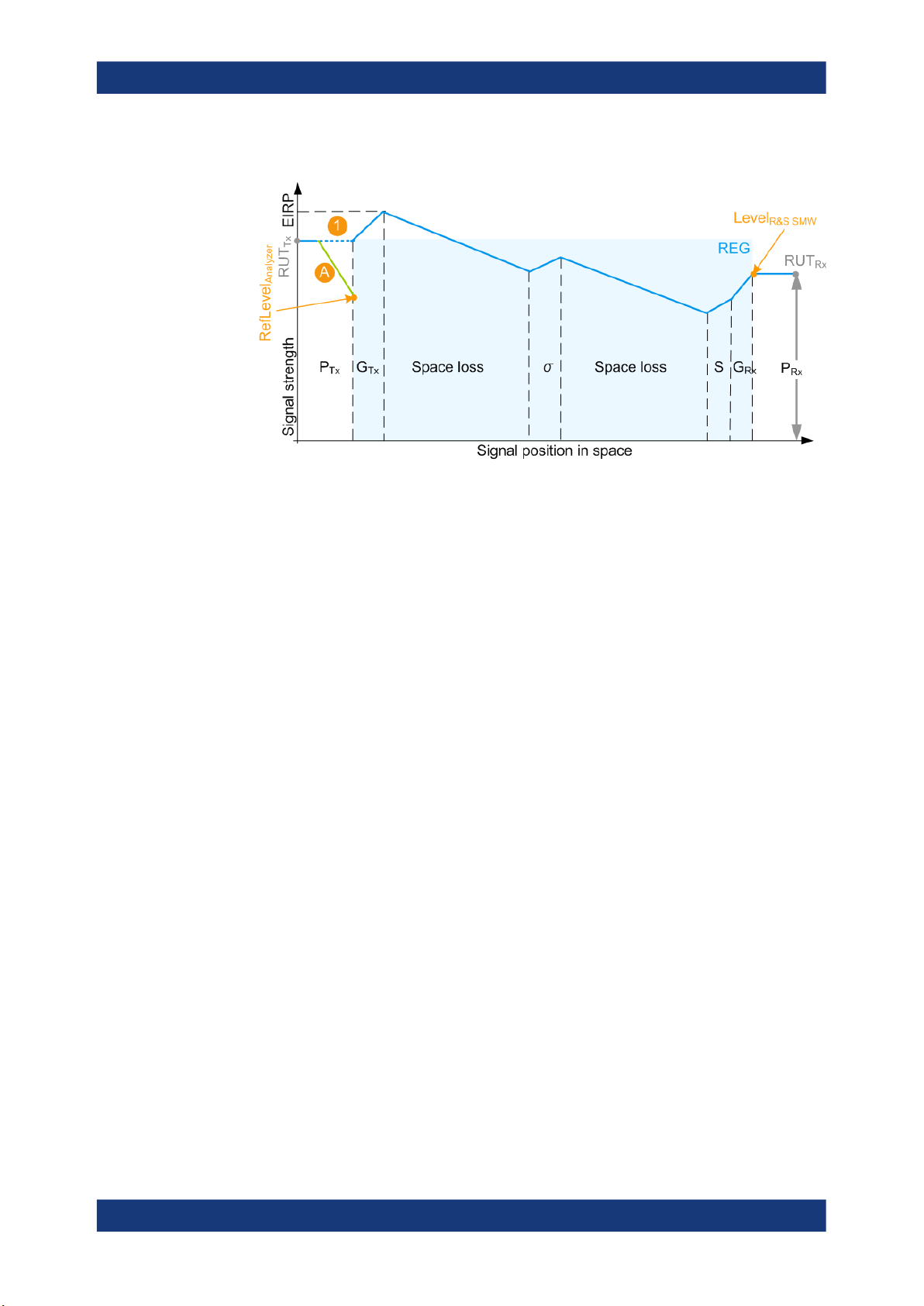
RefLevel
The reference level (RefLevel
test setup. The RefLevel
●
"Test Setup > Conducted Test"
RefLevel
Analyzer
Analyzer
calculation
Analyzer
, [dBm] = PTx - A
) depends on the external attenuation A and on the
Analyzer
is calculated as follows:
Where:
– PTx is the radar transmitter power
(see "Radar under test (RUT) settings" on page 28)
– A is the attenuation of the external attenuator
16User Manual 1177.6252.02 ─ 14
R&S®SMW-K78
About the Radar Echo Generation option
Important parameters and interdependencies
(see "Ext. Attenuator (Analyzer)" on page 29)
Figure 2-6: P_Rx calculation (simplified representation, "Ext. Attenuator A = A dB", "Test Setup =
A = External attenuation
1 = External attenuation merely protects the input of the analyzer; in does not change the calculated
PRx value
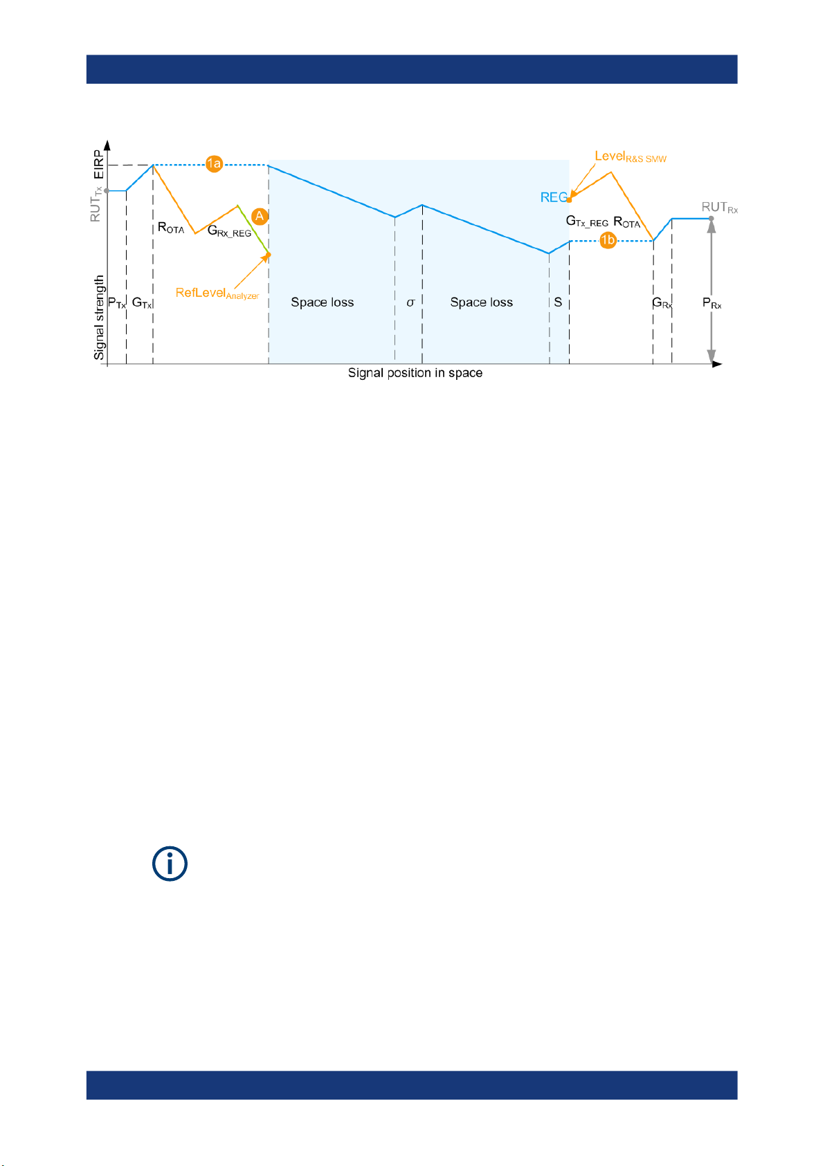
●
"Test Setup > OTA Test"
RefLevel
- 20log10(R
Conducted")
, [dBm] = PTx + GTx + G
Analyzer
) - A
OTA
+ 20log10(c0) - 20log10(f) - 20log10(4π)
Rx_REG
Where:
– PTx is the radar transmitter power
(see "Radar under test (RUT) settings" on page 28)
– GTx and G
are the antenna gains of the transmitting at the radar and the
Rx_REG
receiving antennas at the REG
(see "Radar under test (RUT) settings" on page 28 and "OTA tests settings"
on page 27)
– f is the dedicated frequency
(see "Dedicated Frequency" on page 36)
–
c0 ≈ 3*108 m/s is the speed of light
– A is the attenuation of the external attenuator
(see "Ext. Attenuator (Analyzer)" on page 29)
– R
is the distance between the transmitting and receiving antennas of the
OTA
RUT and the REG
(see "OTA tests settings" on page 27)
17User Manual 1177.6252.02 ─ 14
R&S®SMW-K78
About the Radar Echo Generation option
Important parameters and interdependencies
Figure 2-7: P_Rx calculation (simplified representation, "Ext. Attenuator A = A dB", "Test Setup =
A = External attenuation
1a, 1b = External attenuation A, R
Level
R&S SMW
OTA")
calculation
OTA
, G
Rx_REG
, and G
do not change the calculated PRx value
Tx_REG
The signal power level at the RF outputs of the R&S SMW is configured in the way that
the power level received by the RUT is the calculated PRx of the whole scenario.
This is true irrespectively of the test setup and whether the P
with the Radar equation or manually.
The calculated Level
R&S SMW
is indicated with the parameter Level for Simulation. The
displayed value considers also the following:
●
Enabled level offset ("RF > RF Level > Offset")
●
Current signal routing ("System Configuration > I/Q Stream Mapper > Stream A/B
to RF A/B")
2.4.2.2 Setting the REG input and output levels (RefLevel
The reference level of the analyzer RefLevel
is important value for the calculation
Analyzer
of the required output level at the R&S SMW. The analyzer and the R&S SMW must be
properly connected.
Analyzer
values are calculated
Rx,j
and Level
R&S SMW
)
Correct calculation and leveling
We recommend that you connect the instruments via USB (or LAN) and configure their
settings from the R&S SMW and the REG dialog.
Do not change the level settings of both, the generator and the analyzer manually. Use
the following alternatives instead:
●
Set the parameter "System Loss" to compensate for additional attenuation.
●
Set the parameter "RF > RF Level > Offset" to add a level shift.
18User Manual 1177.6252.02 ─ 14

R&S®SMW-K78
About the Radar Echo Generation option
Important parameters and interdependencies
RefLevel
Analyzer
adjustment
To ensure correct leveling at the beginning of the simulation, the R&S SMW performs
the following:
●
Calculates the required reference level (RefLevel
) depending on the Test
Analyzer
Setup.
●
Verifies whether the calculated reference level is within the permissible value range
of the analyzer.
(see the status indication in the parameter Set Ref. Level on Analyzer)
●
Verifies whether the current reference level in the analyzer is equal to the calculated value.
If an update is indicated, select "Set Ref. Level on Analyzer" to set the level to the
calculated RefLevel
Analyzer
value.
The R&S SMW does not monitor the reference level in the analyzer during operation.
Subsequent changes of the reference level value are not considered.
Level
R&S SMW
adjustment
To ensure correct leveling, the R&S SMW performs the following:
●
Calculates the required output level Level
R&S SMW
and indicates it with the parame-
ter Level for Simulation.
(see "Level
●
Verifies whether the calculated level is within the permissible value range.
R&S SMW
calculation" on page 18)
(see the status indication in the parameter Adjust Dedicated Level)
●
Identifies the dedicated connectors, i.e. all connectors to that the signal of the REG
block is routed.
("System Configuration > I/Q Stream Mapper > Stream A/B to RF A/B")
●
Verifies whether the current output level at the dedicated connector is equal to the
calculated value.
If an update is indicated, select "Adjust Dedicated Level" to set the output level to
the calculated value.
2.4.3 Doppler frequency shift calculation
The Doppler frequency shift fD of the signal returning for an object is calculated as follows:
fD = m*2*v*f/c
Where:
●
m is a coefficient that indicates whether the object is approaching to or departing
from the radar:
– m = -1, if "End Range" ≥ "Start Range" (departing object)
– m = 1 otherwise (approaching object)
0
19User Manual 1177.6252.02 ─ 14

R&S®SMW-K78
2.4.4 Delay calculation
About the Radar Echo Generation option
Important parameters and interdependencies
●
|v| is the velocity of the object in the direction of travel and is given by the absolute
value of the radial velocity.
(see "Object Velocity" on page 41)
●
f is the dedicated frequency
(see "Dedicated Frequency" on page 36)
●
c0 ≈ 3*108 m/s is the speed of light
Because objects move with a constant velocity, the absolute values of the Doppler frequency shift fD is a constant value and is calculated once for the carrier frequency. Dif-
ferent spectral components are applied with different doppler frequency shifts fD. The
Doppler frequency of a moving object that moves one way and then stops is fD during
the movement and fD = 0 at the distance "End Range". The Doppler frequency of an
object that moves fort and backwards alternates between the 2 values ±fD.
See the example on Figure 3-4.
The delay τ of each returned pulse is calculated as follows:
τj = 2*(Rj - R
OTA
) / c
0
Where:
●
Rj is the range per object j
(see "(Start) Range" on page 40 and "End Range" on page 40)
●
R
is the distance between the transmitting and receiving antennas of the RUT
OTA
and the REG
(see "OTA tests settings" on page 27)
R
= 0, if "Test Setup" on page 26 > "Conducted Test" is used.
OTA
●
c0 ≈ 3*108 m/s is the speed of light
The signal delay τj is a function of the range Rj.
For static objects and static + moving objects, the signal delay τj is a constant value
and has to be calculated once. For moving objects, the delay is calculated along the
whole trajectory, i.e. form the "Start Range" to the "End Range" values.
Eliminating the blind zone BZ effect for pulse sequences with a constant PRF
The minimum delay τj depends on the blind zone (BZ) of the REG (see "System
Latency (Blind Zone/ BZ)" on page 34). The theoretical minimum range R
min
is the
distance at that the radar and the object are colocated and can be achieved only if the
tBZ = 0.
The blind zone (also referred as system latency) is the processing time of the REG for
each incoming pulse, that is the time it takes the R&S SMW and the R&S FSW to process the radar signal. Per default, the τj ≥ tBZ. The first retransmitted pulse is sent after
the system latency time period has elapsed, see Figure 2-8.
20User Manual 1177.6252.02 ─ 14
R&S®SMW-K78
About the Radar Echo Generation option
Important parameters and interdependencies
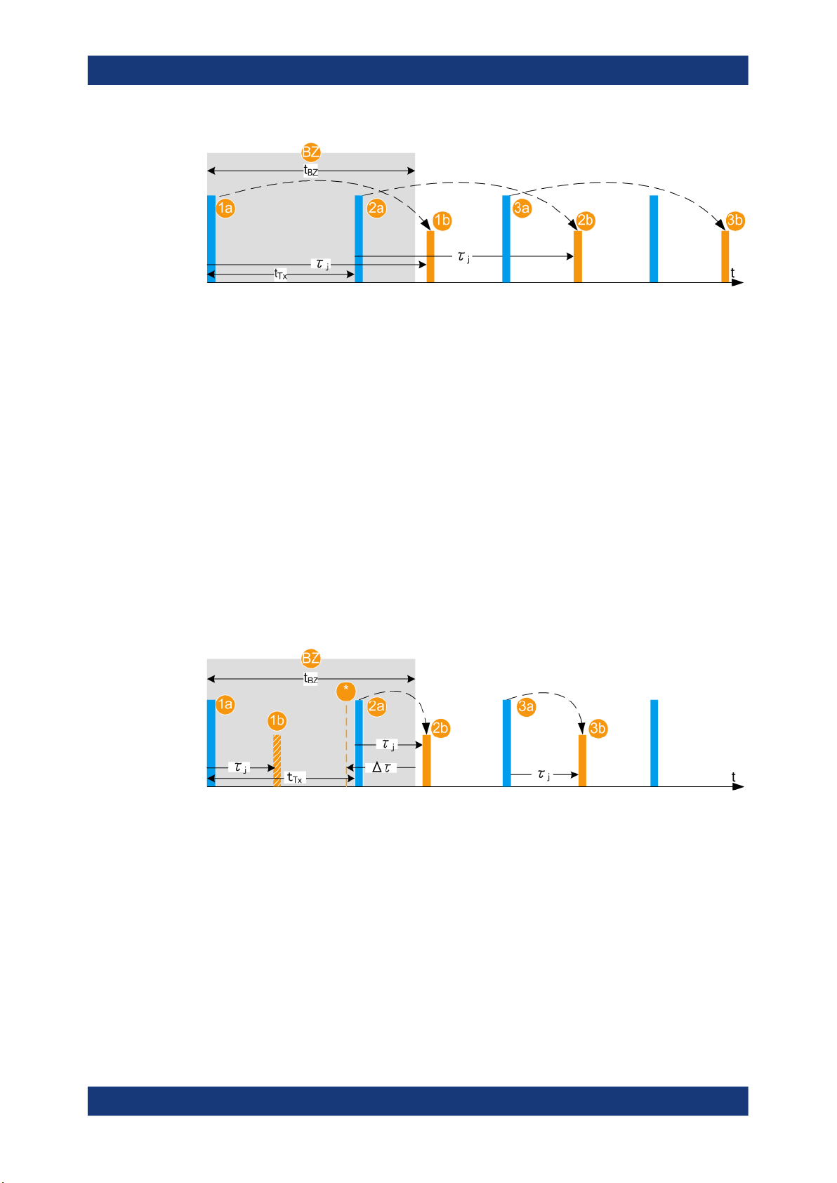
Figure 2-8: Effect of the blind zone (BZ)
BZ =
t
BZ
1a, 1b =
2a and 2b, 3a and 3b = Tx and Rx pulse pairs
τ
j
t
Tx
Blind zone of the 1st pulse
= Blind zone duration
1st Tx pulse and first Rx pulse (echo), retransmitted to the RUT
= Delay
= 1/PRF is the pulse repetition interval
If the radar signal is a pulse sequence with a constant known pulse repetition frequency (PRF), the bind zone limitation can be overcome. With enabled parameter Use
Radar Range Ambiguity to reduce Min. Range, the REG retransmits the first echo so
that once received in the RUT, this echo looks like it is the response of a subsequent
(nth) transmit pulse. The delay is, however, τj < tBZ. The nth pulse is indicated with the
parameter First Echo to Pulse#. The value depends on the PRF, tBZ and the range Rj.
This process is illustrated on Figure 2-9. The example uses the same sequence as on
Figure 2-8 but τj < tBZ. The software calculated the value Δτj = tBZ - τj and determines
the earliest possible time point, after that an echo can be retransmitted. In this example, the first echo pulse is the response of the 2nd transmitted pulse.
Figure 2-9: Effect of the parameter "Use Radar Range Ambiguity to Reduce min. Range = On"
BZ =
t
BZ
PRF = Pulse repetition frequency; a known constant value
t
Tx
τ
j
Δτ
1a, 2a, 1b =
1b =
* = The earliest possible time point, after that an echo can be retransmitted
Blind zone of the 1st pulse
= Blind zone duration
= 1/PRF is the pulse repetition interval
= Delay
= tBZ - τ
j
Pulses and echoes during the blind zone of the 1st pulse
Theoretical echo of the 1st Tx pulse (not transmitted)
21User Manual 1177.6252.02 ─ 14

R&S®SMW-K78
2.4.5 System latency calibration
About the Radar Echo Generation option
General recommendations
2a = Tx pulse, as transmitted by the RUT; this pulse number is indicated with the parameter First
Echo to Pulse#
2b = Rx pulse (echo), retransmitted to the RUT
3a and 3b = Tx and Rx pulse pairs
The REG system latency can be estimated automatically or set manually.
Manual calibration
The REG blind zone is set manually with the parameter System Latency (Blind Zone/
BZ).
See Chapter 4.8, "Estimating the system latency time roughly", on page 59 for an
example on how to estimate and correct the system latency manually.
Automatic calibration
If the trigger signal of the R&S SMW is fed to the analyzer, the system latency can be
estimated automatically. The trigger output connector depends on the test setup up
and the signal routing ("System Configuration > I/Q Stream Mapper"). Observe the
Show Trigger Connector information and connect the indicated output.
The system latency is measured once, after the automatic calibration is selected. The
estimated value corresponds to the processing time of the REG, i.e. the processing
time of the R&S SMW and the analyzer. The value is measured for the current REG
configuration, in particular the selected signal routing. Do not change the signal routing
afterwards.
The estimated value can deviate form the real system latency. Errors in the system
latency result in a constant offset applied to all objects. System latency errors can be
compensated by adding a correction value (Correction Values).
See:
●
Data sheet for information on the system latency calibration error
●
Figure 4-1 and Figure 4-2 for an overview of the default connectors and connec-
tions
●
Chapter 4.8, "Estimating the system latency time roughly", on page 59 for general
example on how to compensate for system latency errors
2.5 General recommendations
Consider the following general recommendations for best results:
1. Use short connection cables
2. Connect all required cables between the REG and the RUT: reference frequency,
data, control, trigger, RF signals
22User Manual 1177.6252.02 ─ 14

R&S®SMW-K78
About the Radar Echo Generation option
General recommendations
3. Follow the rules for overload protection
4. Configure the "System Configuration" settings, in particular the signal routing form
the BB IN block to the REG blocks and to the RF outputs.
5. Set the RF frequency and if necessary a level limit and a level offset.
6. Do not change the parameter "I/Q Modulator > Digital Impairments > I/Q Delay".
A value different than 0 adds an extra delay. When observed on the RUT, all
objects are shifted with a constant delay
7. Set the reference frequency source
8. Configure the Radar Setup settings. Configure one ore more object.
9. Adjust the REG input level
10. Adjust the REG output level
11. Adjust the RF at the analyzer
12. If necessary, estimate the system latency automatically
For step-by-step instructions, see Chapter 4, "How to generate radar echo signals",
on page 49.
23User Manual 1177.6252.02 ─ 14

R&S®SMW-K78
3 Radar echo generation configuration and
Radar echo generation configuration and settings
Radar Setup settings
settings
This section describes the related settings.
The remote commands required to define these settings are described in Chapter 5,
"Remote-control commands", on page 61.
For step-by-step instructions, see Chapter 4, "How to generate radar echo signals",
on page 49.
The Radar Echo Generation settings are grouped into several tabs. The "Radar Setup"
tab comprises the settings of your test setup, like the setup type, RUT Tx power,
antenna gains at the transmitter and the receiver side, or attenuations. The "Simulation
Setup" tab is where you calibrate the REG. In the "Object Configuration" tab, you can
describe the objects for that the echoes are generated. If at least one object is configured and the REG is activated, the graph in the "Object Preview" tab visualizes the variation of the received power.
● Radar Setup settings...............................................................................................24
● Overview test setup.................................................................................................30
● Restart settings....................................................................................................... 31
● Simulation Setup settings........................................................................................33
● Object configuration settings...................................................................................37
● Radar cross-section RCS setup settings................................................................ 44
● Object preview settings...........................................................................................47
3.1 Radar Setup settings
This dialog provides access to the default and the "Save/Recall" settings, and to the
power and antenna gain parameters of the radar and the radar echo generator (REG).
The power and gain parameters are required to calculate the received power Rx.
Access:
1. In the block diagram of the R&S SMW, select "System Config > System Configura-
tion > Fading/Baseband Config > Mode > Radar Echo Generation".
2. Select "Apply" and confirm with "OK".
3. Close the "System Configuration" dialog.
4. In the block diagram, select "REG > Radar Echo Generation"
The Radar Echo Generation dialog box opens and displays the "Radar Setup" settings.
24User Manual 1177.6252.02 ─ 14
R&S®SMW-K78
Radar echo generation configuration and settings
Radar Setup settings
1 2
3
3
3
3
3
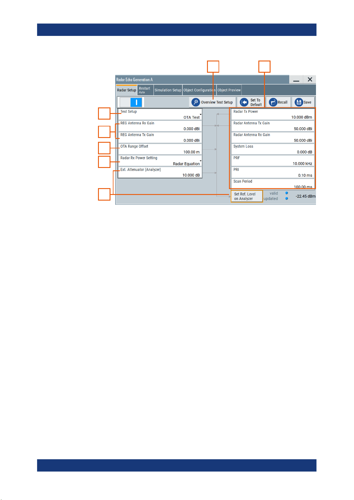
Figure 3-1: Radar Setup: Understanding the displayed information
1 = Test setup overview, see Figure 3-2
2 = Radar under test (RUT) settings
3 = External attenuator and analyzer-related settings
4 = General decision on the radar Rx power settings calculation, see Chapter 2.4.2, "Radar received
power PRx calculation", on page 14
6 = Radar echo generator (REG) settings
7, 5 = Test setup type; in this example: test setup with real radar signal, incl. R&S SMW, and signal ana-
lyzer; the radar signal is transmitted over the air (OTA)
Settings:
State..............................................................................................................................26
Overview Test Setup..................................................................................................... 26
Set to Default................................................................................................................ 26
Save/Recall...................................................................................................................26
Test Setup..................................................................................................................... 26
OTA tests settings......................................................................................................... 27
└ REG Antenna Rx Gain....................................................................................27
└ REG Antenna Tx Gain.................................................................................... 27
└ OTA Range Offset...........................................................................................27
Radar Rx Power Setting................................................................................................27
Radar under test (RUT) settings................................................................................... 28
└ Radar Tx Power..............................................................................................28
└ Radar Antenna Tx Gain.................................................................................. 28
└ Radar Antenna Rx Gain..................................................................................28
└ System Loss................................................................................................... 28
└ PRF.................................................................................................................28
└ PRI..................................................................................................................28
25User Manual 1177.6252.02 ─ 14
R&S®SMW-K78
Radar echo generation configuration and settings
Radar Setup settings
└ Scan Period.................................................................................................... 29
Ext. Attenuator (Analyzer).............................................................................................29
Set Ref. Level on Analyzer............................................................................................29
State
Enables/disables the Radar Echo Generation.
Remote command:
[:SOURce<hw>]:REGenerator[:STATe] on page 64
Overview Test Setup
Opens a dialog that illustrates the required (and connected) equipment and cables for
the configuration selected with the parameter "Test Setup", see Figure 3-2.
The displayed information resumes the settings selected in the "Radar Setup" dialog.
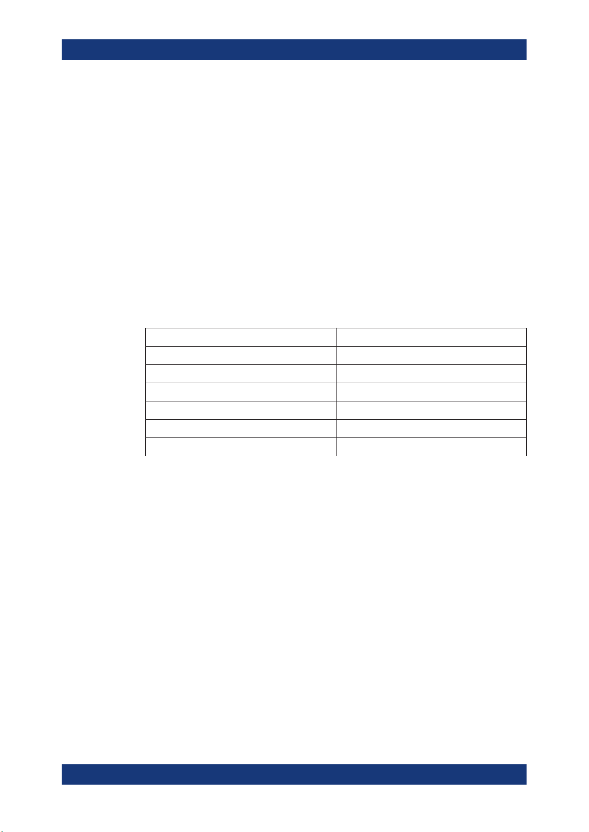
Set to Default
Calls the default settings. The values of the main parameters are listed in the following
table.
Parameter Value
State Off
Test setup Conducted
Tx power of radar 0 dBm
Radar Rx power settings Radar equation
Radar antenna Tx and Rx gain 50 dBi
System loss 0 dB
Remote command:
[:SOURce<hw>]:REGenerator:PRESet on page 65
Save/Recall
Accesses the "Save/Recall" dialog, that is the standard instrument function for saving
and recalling the complete dialog-related settings in a file. The provided navigation
possibilities in the dialog are self-explanatory.
The settings are saved in a file with predefined extension. You can define the filename
and the directory, in that you want to save the file.
See also, chapter "File and Data Management" in the R&S SMW user manual.
Remote command:
[:SOURce<hw>]:REGenerator:CATalog? on page 65
[:SOURce<hw>]:REGenerator:STORe on page 65
[:SOURce<hw>]:REGenerator:LOAD on page 65
Test Setup
Selects how the radar signal is fed from the RUT to the signal analyzer and fed back
from the R&S SMW to the RUT.
26User Manual 1177.6252.02 ─ 14

R&S®SMW-K78
Radar echo generation configuration and settings
Radar Setup settings
Tip: Use the "Overview Test Setup" function to retrieve more information on the current
setup.
See for example Figure 3-2.
Tip: Use the parameter "System Loss" to compensate for system or cable loss.
"Conducted Test"
The radar signal is transmitted over cables; there is a cable connection between the RUT and the radar echo generator (REG).
"OTA Test"
The transmission is performed over-the-air (OTA); there is no cable
connection but Tx and Rx antennas are used in both the RUT and the
REG.
Remote command:
[:SOURce<hw>]:REGenerator:RADar:TSETup on page 69
OTA tests settings
If a "Test Setup > OTA Test" is used, the following parameters are required for the calculation of the Rx signal power, the ranges and the reference level of the analyzer.
The calculation is performed according to the Radar equation.
REG Antenna Rx Gain ← OTA tests settings
Sets the gain of receiving antenna that is connected to the REG (G
Rx_REG
).
Remote command:
[:SOURce<hw>]:REGenerator:RADar:ANTenna:REG:GAIN:RX on page 71
REG Antenna Tx Gain ← OTA tests settings
Sets the gain of transmitting antenna that is connected to the REG (G
Tx_REG
).
Remote command:
[:SOURce<hw>]:REGenerator:RADar:ANTenna:REG:GAIN:TX on page 71
OTA Range Offset ← OTA tests settings
Sets the distance between the transmitting and receiving antennas of the RUT and the
REG (R
OTA
).
Remote command:
[:SOURce<hw>]:REGenerator:RADar:OTA:OFFSet on page 72
Radar Rx Power Setting
Determines how the radar receive power is calculated.
"Radar Equation"
The radar Rx power is calculated according to the radar equation,
see Chapter 2.4.2, "Radar received power PRx calculation",
on page 14.
Each object is described by its radar cross-section (RCS).
To select the applied model and its settings, select "Object Configuration > RCS...".
See Chapter 3.6, "Radar cross-section RCS setup settings",
on page 44.
27User Manual 1177.6252.02 ─ 14

R&S®SMW-K78
Radar echo generation configuration and settings
Radar Setup settings
"Manual"
The radar equation is not used; you set the P
value of each object
Rx, j
instead.
See Radar Rx Power.
This parameter is useful if your test situation requires a specific Rx
power.
Remote command:
[:SOURce<hw>]:REGenerator:RADar:POWer:MODE on page 71
Radar under test (RUT) settings
Refer to the product documentation of the RUT for information on its characteristics.
The following input parameters are required for the calculation of the Rx signal power
PRx of the signal returning to the radar antenna.
The calculation is performed for each object and according to the Radar equation.
Radar Tx Power ← Radar under test (RUT) settings
Sets the radar transmit power PTx.
If the "Radar Antenna Tx Gain = 0 dBi", the PTx value corresponds to the EIRP of the
radar (see Figure 2-4).
Remote command:
[:SOURce<hw>]:REGenerator:RADar:POWer:TX on page 70
Radar Antenna Tx Gain ← Radar under test (RUT) settings
Sets the antenna gain of transmitting antenna G
Tx
Remote command:
[:SOURce<hw>]:REGenerator:RADar:ANTenna:GAIN:TX on page 71
Radar Antenna Rx Gain ← Radar under test (RUT) settings
Sets the antenna gain of receiving antenna G
Rx
Remote command:
[:SOURce<hw>]:REGenerator:RADar:ANTenna:GAIN:RX on page 71
System Loss ← Radar under test (RUT) settings
Gain to compensate for system or cable loss.
Remote command:
[:SOURce<hw>]:REGenerator:RADar:POWer:LOSS on page 70
PRF ← Radar under test (RUT) settings
Sets the pulse repetition frequency (PRF).
The value is used for the function "Simulation Setup" > Use Radar Range Ambiguity to
reduce Min. Range.
PRI and PRF are interdependent, setting on of the value changes the other.
Remote command:
[:SOURce<hw>]:REGenerator:SIMulation:PRF on page 70
PRI ← Radar under test (RUT) settings
Sets the pulse repetition interval (PRI), where PRI = 1 / PRF.
28User Manual 1177.6252.02 ─ 14

R&S®SMW-K78
Radar echo generation configuration and settings
Radar Setup settings
PRI and PRF are interdependent, setting on of the value changes the other.
For RCS swerling models II and IV, a new random RCS value is generated according
to the duration of the "PRI" (pulse-to-pulse).
Remote command:
[:SOURce<hw>]:REGenerator:SIMulation:PRI on page 70
Scan Period ← Radar under test (RUT) settings
Set the time which the radar needs for one scan.
For RCS swerling models I and III, a new random RCS value is generated according to
the duration of the "Scan Period" (scan-to-scan).
Remote command:
[:SOURce<hw>]:REGenerator:SIMulation:SPERiod on page 71
Ext. Attenuator (Analyzer)
The parameter is enabled only if FSW is connected to the R&S SMW.
Connect an external attenuator to reduce the radar Tx power and to protect the input
stage of the analyzer, see Chapter 2.3, "Analyzer and receiver overload protection",
on page 12.
Set the parameter to the attenuation (A) of your external attenuator.
Remote command:
[:SOURce<hw>]:REGenerator:RADar:ANALyzer:POWer:ATTenuator
on page 72
Set Ref. Level on Analyzer
Indicates the calculated reference level and sets this level in the R&S FSW; see Chap-
ter 2.4.2.1, "Calculating the REG input and output levels (RefLevel
)", on page 15.
SMW
Analyzer
and Level
R&S
The operation "Set Ref. Level on Analyzer" is enabled and a value is displayed only if
FSW is connected to the R&S SMW.
Status LED and status information indicate the following:
●
Valid + blue LED: the calculated reference level is within the permissible value
range of the R&S FSW.
●
Valid + orange LED: indicates that the reference level is outside the permissible
value range; the operation "Set Ref. Level on Analyzer" is disabled.
●
Update + orange LED: the reference level of the R&S FSW deviates from the calculated value; execute the operation "Set Ref. Level on Analyzer".
●
Update + blue LED: the reference level of the R&S FSW is equal to the calculated
value.
Remote command:
[:SOURce<hw>]:REGenerator:RADar:ANALyzer:POWer:REFerence?
on page 72
[:SOURce<hw>]:REGenerator:RADar:ANALyzer:POWer:APPLy on page 73
[:SOURce<hw>]:REGenerator:RADar:ANALyzer:STATus? on page 73
29User Manual 1177.6252.02 ─ 14
 Loading...