

Rohde&Schwarz R&S®SMW200A LTE/5G LogFile Generation user manual User Manual

R&S®SMW-K81
Log File Generation
User Manual
(;ÜçÏ2)
1178896502
Version 07

This document describes the following software options:
●
R&S®SMW-K81 Log File Generation (1413.4539.0x)
This manual describes firmware version FW 5.00.044.xx and later of the R&S®SMW200A.
© 2021 Rohde & Schwarz GmbH & Co. KG
Mühldorfstr. 15, 81671 München, Germany
Phone: +49 89 41 29 - 0
Email: info@rohde-schwarz.com
Internet: www.rohde-schwarz.com
Subject to change – data without tolerance limits is not binding.
R&S® is a registered trademark of Rohde & Schwarz GmbH & Co. KG.
Trade names are trademarks of the owners.
1178.8965.02 | Version 07 | R&S®SMW-K81
The following abbreviations are used throughout this manual: R&S®SMW200A is abbreviated as R&S SMW, R&S®WinIQSIM2 is
abbreviated as R&S WinIQSIM2; the license types 02/03 are abbreviated as 0x.

R&S®SMW-K81
1 Welcome to the logfile generation option............................................5
1.1 What's new.....................................................................................................................5
1.2 Documentation overview..............................................................................................5
1.2.1 Getting started manual....................................................................................................6
1.2.2 User manuals and help................................................................................................... 6
1.2.3 Tutorials...........................................................................................................................6
1.2.4 Service manual............................................................................................................... 6
1.2.5 Instrument security procedures.......................................................................................6
1.2.6 Printed safety instructions............................................................................................... 7
1.2.7 Data sheets and brochures............................................................................................. 7
1.2.8 Release notes and open source acknowledgment (OSA).............................................. 7
Contents
Contents
1.2.9 Application notes, application cards, white papers, etc...................................................7
1.3 Notes on screenshots...................................................................................................7
2 LTE/IoT logfile generation..................................................................... 8
2.1 Required options...........................................................................................................8
2.2 Output files.................................................................................................................... 8
2.2.1 Filenames........................................................................................................................8
2.2.2 Extended logfiles contents............................................................................................ 13
2.2.3 Summary logfiles contents............................................................................................ 17
2.3 Signal processing chains and logging points..........................................................17
2.4 How to use the logfile generation functionality....................................................... 22
2.5 Logfile generation settings........................................................................................ 23
2.6 Remote-control commands........................................................................................27
3 5G NR logfile generation..................................................................... 32
3.1 Required options.........................................................................................................32
3.2 Output files.................................................................................................................. 32
3.3 How to generate logfiles.............................................................................................33
3.4 Logfile generation settings........................................................................................ 33
3User Manual 1178.8965.02 ─ 07

R&S®SMW-K81
3.5 Logging commands.................................................................................................... 34
Contents
List of commands................................................................................ 36
Index......................................................................................................37
4User Manual 1178.8965.02 ─ 07

R&S®SMW-K81
1 Welcome to the logfile generation option
Welcome to the logfile generation option
Documentation overview
Generating logfiles for design cross-verification
If equipped with the option R&S SMW-K81, your R&S SMW can create logfiles for
exchanging intermediate results of different logging points in the signal processing
chain.
Analyzing the content of the logfiles can help you to verify the signal processing chain
in both the DL and UL direction. The intermediate results provide a basis for enhanced
debugging. By loading the coded bitstream from the instrument into an Rx software
module for offline analysis in a simulation environment, the FEC implementation in
DUT is verified. You can also compare the coded stream to the bitstreams from a Tx
software module. The logfiles generation functionality can also be remote controlled,
so that the design flow can be optimized and the process automated.
This user manual contains a description of the functionality that the application provides, including remote control operation.
All functions not discussed in this manual are the same as in the base unit and are
described in the R&S SMW user manual. The latest version is available at:
www.rohde-schwarz.com/manual/SMW200A
Installation
You can find detailed installation instructions in the delivery of the option or in the
R&S SMW service manual.
1.1 What's new
This manual describes firmware version FW 5.00.044.xx and later of the
R&S®SMW200A.
Compared to the previous version there are editorial changes only.
1.2 Documentation overview
This section provides an overview of the R&S SMW user documentation. Unless specified otherwise, you find the documents on the R&S SMW product page at:
www.rohde-schwarz.com/manual/smw200a
5User Manual 1178.8965.02 ─ 07

R&S®SMW-K81
1.2.1 Getting started manual
1.2.2 User manuals and help
Welcome to the logfile generation option
Documentation overview
Introduces the R&S SMW and describes how to set up and start working with the product. Includes basic operations, typical measurement examples, and general information, e.g. safety instructions, etc. A printed version is delivered with the instrument.
Separate manuals for the base unit and the software options are provided for download:
●
Base unit manual
Contains the description of all instrument modes and functions. It also provides an
introduction to remote control, a complete description of the remote control commands with programming examples, and information on maintenance, instrument
interfaces and error messages. Includes the contents of the getting started manual.
●
Software option manual
Contains the description of the specific functions of an option. Basic information on
operating the R&S SMW is not included.
The contents of the user manuals are available as help in the R&S SMW. The help
offers quick, context-sensitive access to the complete information for the base unit and
the software options.
All user manuals are also available for download or for immediate display on the Internet.
1.2.3 Tutorials
The R&S SMW provides interactive examples and demonstrations on operating the
instrument in form of tutorials. A set of tutorials is available directly on the instrument.
1.2.4 Service manual
Describes the performance test for checking compliance with rated specifications, firmware update, troubleshooting, adjustments, installing options and maintenance.
The service manual is available for registered users on the global Rohde & Schwarz
information system (GLORIS):
https://gloris.rohde-schwarz.com
1.2.5 Instrument security procedures
Deals with security issues when working with the R&S SMW in secure areas. It is available for download on the Internet.
6User Manual 1178.8965.02 ─ 07

R&S®SMW-K81
1.2.6 Printed safety instructions
1.2.7 Data sheets and brochures
1.2.8 Release notes and open source acknowledgment (OSA)
Welcome to the logfile generation option
Notes on screenshots
Provides safety information in many languages. The printed document is delivered with
the product.
The data sheet contains the technical specifications of the R&S SMW. It also lists the
options and their order numbers and optional accessories.
The brochure provides an overview of the instrument and deals with the specific characteristics.
See www.rohde-schwarz.com/brochure-datasheet/smw200a
The release notes list new features, improvements and known issues of the current
firmware version, and describe the firmware installation.
The open-source acknowledgment document provides verbatim license texts of the
used open source software.
See www.rohde-schwarz.com/firmware/smw200a
1.2.9 Application notes, application cards, white papers, etc.
These documents deal with special applications or background information on particular topics.
See www.rohde-schwarz.com/application/smw200a and www.rohde-schwarz.com/
manual/smw200a
1.3 Notes on screenshots
When describing the functions of the product, we use sample screenshots. These
screenshots are meant to illustrate as many as possible of the provided functions and
possible interdependencies between parameters. The shown values may not represent
realistic usage scenarios.
The screenshots usually show a fully equipped product, that is: with all options installed. Thus, some functions shown in the screenshots may not be available in your particular product configuration.
7User Manual 1178.8965.02 ─ 07

R&S®SMW-K81
2 LTE/IoT logfile generation
2.1 Required options
LTE/IoT logfile generation
Output files
The generation of logfiles requires:
●
Standard or wideband baseband generator (R&S SMW-B10/-B9)
●
Option EUTRA/LTE (R&S SMW-K55)
●
Option Cellular IoT (R&S SMW-K115)
●
Option log files generation (R&S SMW-K81)
Two options R&S SMW-K81 are required in the fowlloing cases:
– For generating logfiles for more than one transmission antenna simultaneously.
– If coupled baseband sources are used.
2.2 Output files
The instrument stores the output logfiles in a user-defined network directory, selected
with the parameter Output Path. The logfiles are named according to the naming conventions described in Chapter 2.2.1, "Filenames", on page 8. Description of the
available file formats is listed in "File formats" on page 8.
File formats
Generally, the logfiles are generated in two file formats:
●
Bitstream
The logfile contains a sequence of "1" and "0"; one value per line
The logfile of the PHICH contains also the entry "-" that corresponds to DTX.
●
IQ samples
The logfile contains pairs of I and Q samples; the I and Q components alternate at
each line
File format "IQ samples" is used for the logfiles generated for the logging points after
"Modulation Mapping". The other logfiles are output in a Bitstream format.
Exceptions are the extended DCI/UCI logfiles, and the summary logfile (see Chap-
ter 2.2.2.1, "Extended DCI logfile", on page 13 and Chapter 2.2.2.2, "Extended UCI
logfile", on page 16).
2.2.1 Filenames
The generated logging files are named according to the following naming structure:
[<Preamble>_]<Frame#>_<Subframe#>|<TRANSM#>_<Channel>[-<Format>]
[_<User/Allocation#>|<DCI#>|<Group#>]_<Point#>[_<CW#>|<LAY#>|
<ANT#>][_<RV#>]_<PointName>[_<CodeBlock#>].dat
8User Manual 1178.8965.02 ─ 07
R&S®SMW-K81
LTE/IoT logfile generation
Output files
Exceptions are the extended DCI/UCI logfiles, and the summary logfile. The filenames
of these logfiles are as follows:
[<Preamble>_]ExtendedDciLog_<BB#>.txt
●
[<Preamble>_]ExtendedUciLog_<BB#>.txt
●
[<Preamble>_]SummaryLogfile_<BB#>.txt
●
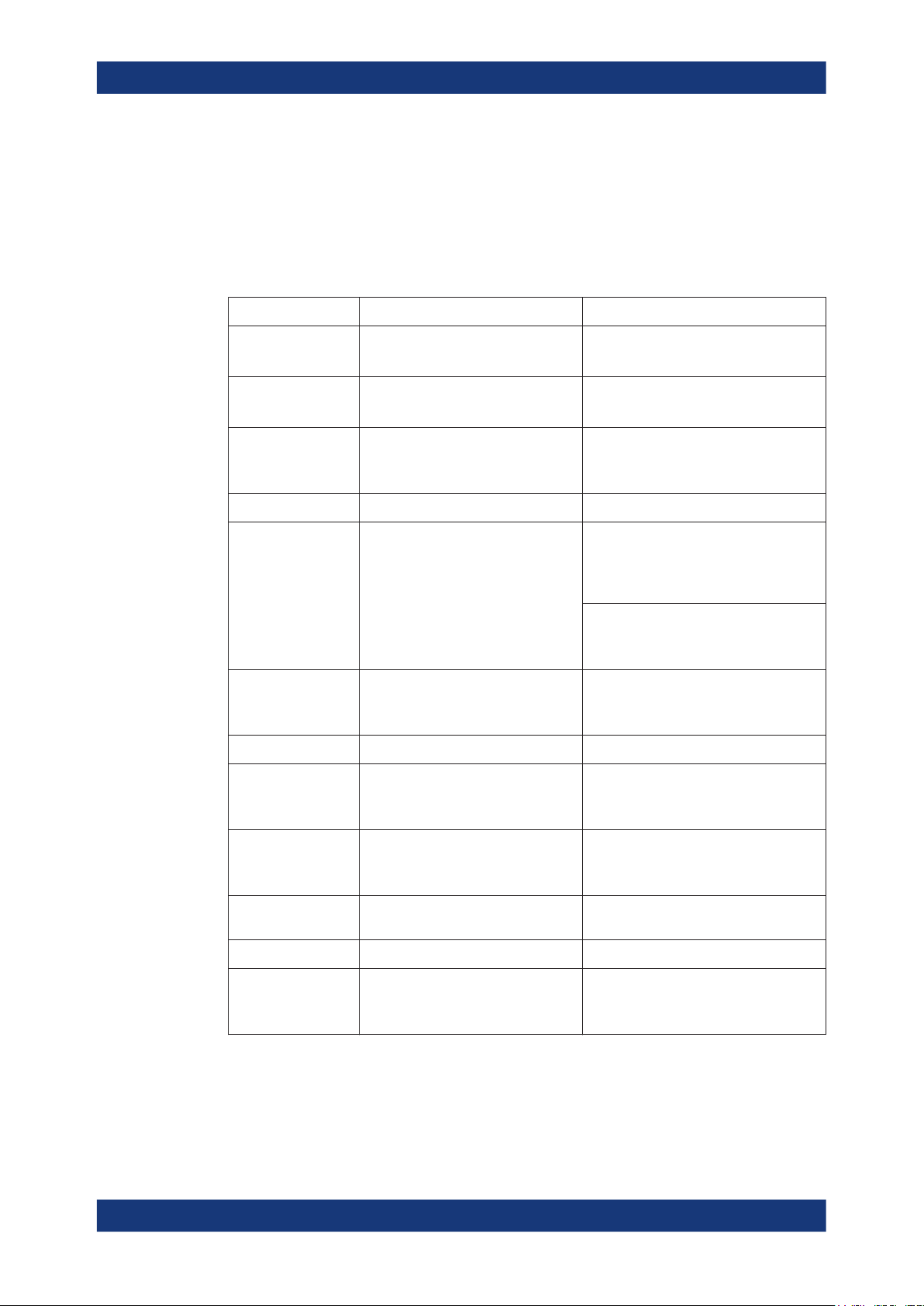
Table 2-1: Filename structure
<Preamble>
<Frame#>
<Subframe#>
<TRANSM#>
<Channel>
<User>
<Allocation#>
Description Value range
Preamble with default syntax
EUtraLog_<Entity#>
Frame number F000 to F873
Subframe number
Starting subframe number (NPBCH/
NPDSCH/NPDCCH)
eMTC/NB-IoT transmission TRANSM01 to TRANSM20
Channel name DL: PBCH | PCFICH | PHICH | PDCCH |
PDSCH, PUSCH, PUCCH, PUSCH
DRS, PUCCH DRS
NPUSCH, NPUSCH DRS
PDSCH allocation only ALL000 to ALL101
Entity#: 0 to 7
NPBCH*): F000, F064, F128, etc.
SF0 to SF9
PDSCH | PMCH
DL: NPBCH | NPDSCH | NPDCCH |
NPDSCH-SIB1 | PDSCH-SIB1BR
UL: PUSCH | PUCCH PUSCHDRS |
PUCCHDRS | SRS
UL: NPUSCH
USER1 to USER4
<DCI#>
<Group#>
<Format>
<Point#>
<CW#>
PDCCH allocation only
Each PDCCH DCI is logged individually
PHICH group
An individual file is generated for each
PHICH group
PUCCH format F1 | F1A | F1B | F2 | F2A | F2B | F3 | F4 |
Logging point number See Table 2-2.
PDSCH, PUSCH/NPUSCH allocations
only
Codeword
DCI00 to DCI19
Group00 | Group01
F5
CW0 | CW1 (PDSCH, PUSCH)
CW0 (NPUSCH, PDSCH-SIB1BR)
9User Manual 1178.8965.02 ─ 07
R&S®SMW-K81
LTE/IoT logfile generation
Output files
<LAY#>
<ANT#>
<AP#>
<RV#>
<PointName>
<CodeBlock#>
<BB#>
*)
NPBCH lasts 640 ms. One logfile contains 64 frames, starting from the frame number
Description Value range
PDSCH, PUSCH, and PUSCH DRS
allocations only
PDSCH-SIB1BR, NPBCH, NPDSCH,
NPUSCH and NPUSCH DRS allocations only
Layer number
Antenna port number DL: ANT1 to ANT4
NPUSCH allocations only
Redundancy version
Logging point designation See Table 2-2
PDSCH and PUSCH allocations only CB00 to CB20
Baseband BBA to BBH
DL: LAY0 to LAY7
DL: LAY0 to LAY1 (NPBCH/NPDCCH/
NPDSCH/NPDSCH-SIB1/PDSCHSIB1BR)
UL: LAY0 to LAY3 (PUSCH and PSUCH
DRS)
UL: LAY0 (NPUSCH and NPUSCH DRS)
DL NB-IoT: ANT1|ANT2
UL: AP10 | AP100 | AP20 | AP21 | AP40 |
AP41 | AP42 | AP43 | AP200 | AP201
RV00 to RV02
indicated as <Frame#>.
There is a fixed cross-reference between the logging point number and the logging
point designation:
●
See Table 2-2.
●
The PUCCH logging points depend on the PUCCH format, see Table 2-3.
●
See Table 2-4.
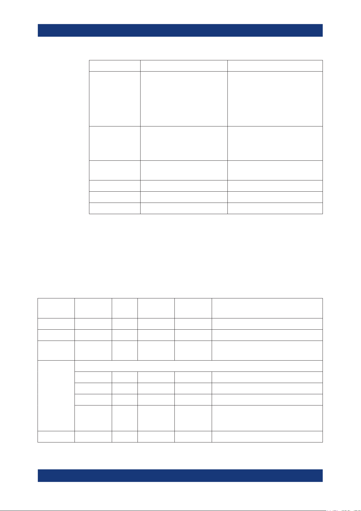
Table 2-2: Logging points overview (DL and PUSCH/NPUSCH)
<Point#> <PointName>
PT00 TB X X X Bits of the transport block
PT01 TBCRC X X X Bits after transport block CRC
PT02 CBCRC X X - Bits after code block CRC
PT03
CCSys X X X Systematic bits
CCPar1 X X X Parity 1 bits
CCPar2 X X X Parity 2 bits
CCTotal X X X (N)PDSCH and PUSCH allocation only
DL
*)
PUSCH NPUSCH Description
One file per code block is generated
Bits after channel coding (one file per code block)
Complete bitstream after channel coding, incl.
systematic, parity 1 and parity 2 bits
PT04 RM X X X Bits after rate matcher (one file per code block)
10User Manual 1178.8965.02 ─ 07
R&S®SMW-K81
LTE/IoT logfile generation
Output files
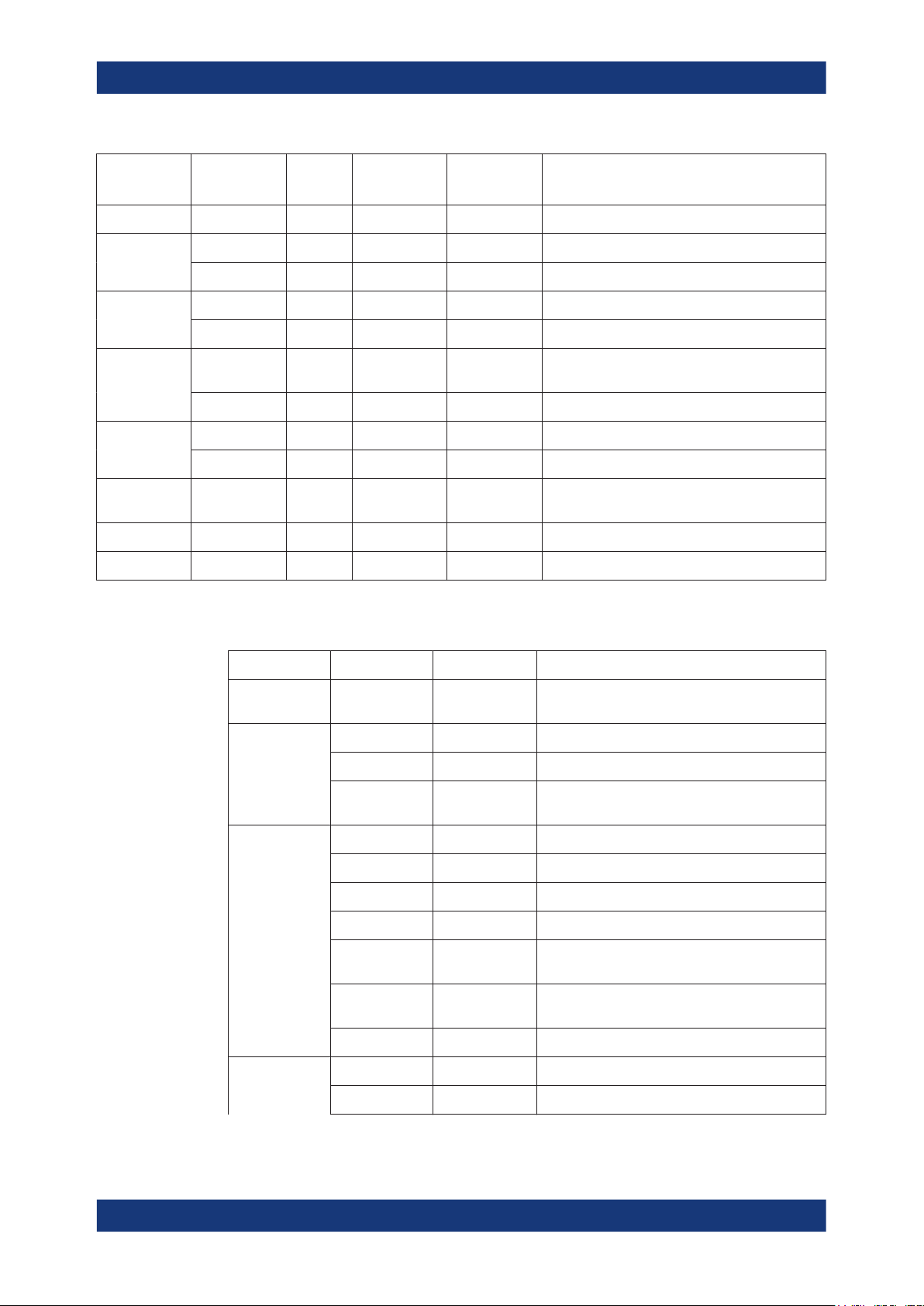
<Point#> <PointName>
PT05 CBCON X X - Bits after code block concatenation
PT06 DL: SCR X - - Bits after scrambling
PT07 DL: MOD X - - IQ-Samples after modulation
PT08 DL: MAP X - - IQ-Samples after layer mapping (one file per
PT09 DL: PREC X - - IQ-Samples after precoding (one file per antenna)
PT10 UL: MAP - X - IQ-Samples after layer mapping (one file per
PT11 UL: DFT - X X IQ-Samples after DFT
PT12 UL: PREC - X - IQ-Samples after precoding (one file per antenna)
UL: MUX - X - Bits after data and control multiplexing
UL: CHI - X X Bits after channel interleaver
UL: SCR - X X Bits after Scrambling
UL: MOD - X X IQ-Samples after modulation
*)
PT02 and PT05 not available for NPBCH, NPDSCH and NPDCCH
DL
*)
PUSCH NPUSCH Description
layer)
layer)
Table 2-3: PUCCH logging points overview per PUCCH format
PUCCH format
F1/F1a/F1b PT00 SCR-BLOCK-
F2/F2a/F2b PT00 UNCODED Uncoded bits
F3 PT00 UNCODED Uncoded bits
F4/F5 PT00 UNCODED Uncoded bits
<Point#> <PointName>
WISE-SPREAD
PT01 SCR Scrambled bits
PT02 CYCLIC-SHIF-
TED
PT01 CODED Coded bits
PT02 SCR Scrambled bits
PT03 MOD IQ-Samples after modulation
PT04 BLOCK-
WISE_SPREAD
PT05 CYCLIC-SHIF-
TED
PT06 DFT-PREC IQ-Samples after DFT transform precoding
Description
Bits after scrambled block-wise spread operation
Bits after cyclic-shift operation
Bits after block-wise spread operation
Bits after cyclic-shift operation
PT01 CRC Bits after block CRC
11User Manual 1178.8965.02 ─ 07
R&S®SMW-K81
LTE/IoT logfile generation
Output files
PUCCH format
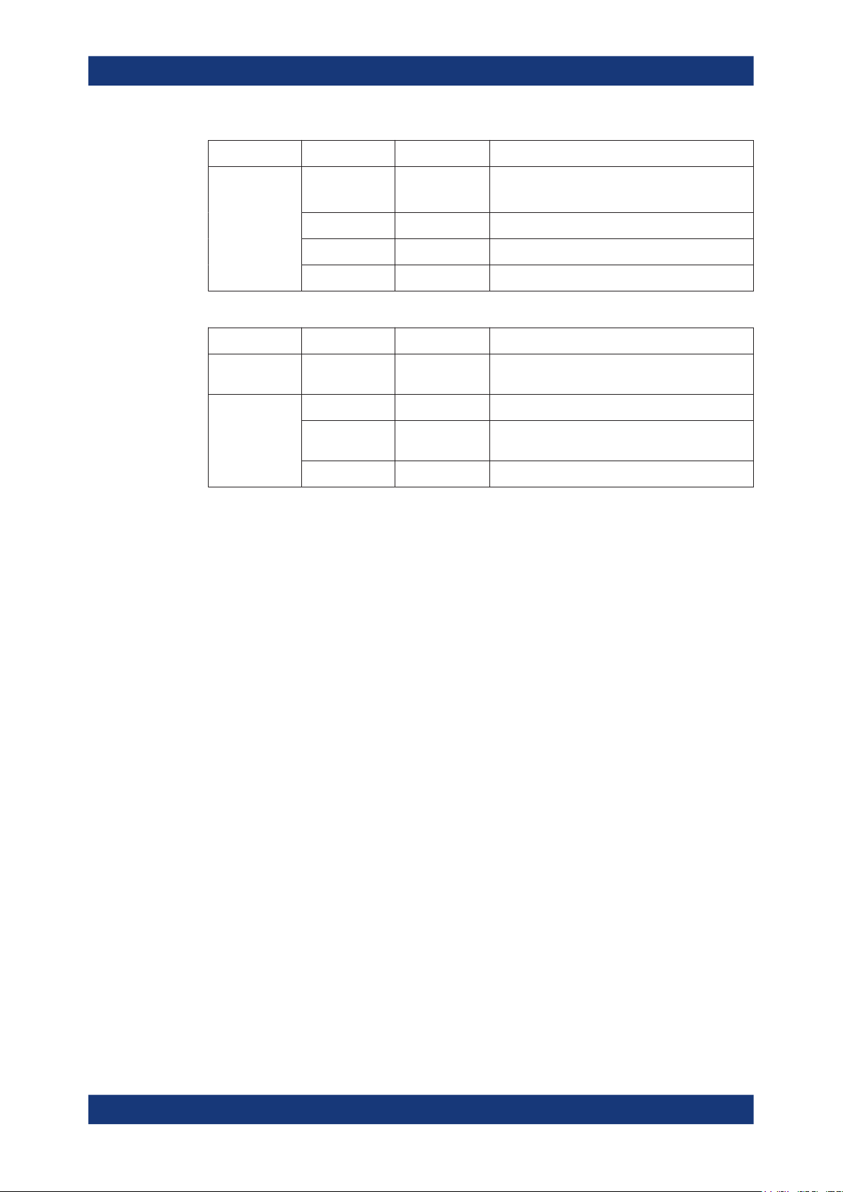
Table 2-4: PUCCHDRS and PUSCHDRS logging points overview
DRS
PUCCHDRS PT00 CYCLIC-SHIF-
PUSCHDRS PT00 CAZAC IQ-Samples after CAZAC sequence generation
<Point#> <PointName>
PT02 CCSys
CCPar1/CCPar2
PT03 RM Bits after rate matcher
PT04 SCR Scrambled bits
PT05 MOD IQ-Samples after modulation
<Point#> <PointName>
TED
PT01 OCC IQ-Samples of OCC (orthogonal cover code)
PT02 PREC IQ-Samples after precoding
Description
Systematic bits
Parity 1 bits/Parity 2 bits
Description
Bits after cyclic-shift operation
sequence
Example: List of the output logfiles for PDSCH
The following output files are generated for one PDSCH channel, configured on an
allocation with index ALL002 in the third subframe (SF2) of the first frame (F000). The
instrument is configured to generate a MIMO signal with two antennas (PREC_ANT1
and PREC_ANT2). Channel coding and scrambling are enabled (CCPar1, CCPar2,
CCSys, CCTotal and SCR). Two codewords (CW0 and CW1) and two layers (LAY0 and
LAY1) are used; three code blocks per code (CB00, CB01, CB02) are generated.
All logging points are enabled and a preamble (EUtraLog_0) is selected.
<User/
Allocation#>_<Point#>[_<CW#>|<LAY#>|<ANT#>]_<PointName>[_<CodeBlock#>].dat
EUtraLog_0_F000_SF2_PDSCH_ALL002_PT00_CW0_TB.dat
EUtraLog_0_F000_SF2_PDSCH_ALL002_PT00_CW1_TB.dat
EUtraLog_0_F000_SF2_PDSCH_ALL002_PT01_CW0_TBCRC.dat
EUtraLog_0_F000_SF2_PDSCH_ALL002_PT01_CW1_TBCRC.dat
EUtraLog_0_F000_SF2_PDSCH_ALL002_PT02_CW0_CBCRC_CB00.dat
EUtraLog_0_F000_SF2_PDSCH_ALL002_PT02_CW1_CBCRC_CB00.dat
EUtraLog_0_F000_SF2_PDSCH_ALL002_PT02_CW0_CBCRC_CB01.dat
EUtraLog_0_F000_SF2_PDSCH_ALL002_PT02_CW1_CBCRC_CB01.dat
EUtraLog_0_F000_SF2_PDSCH_ALL002_PT02_CW0_CBCRC_CB02.dat
EUtraLog_0_F000_SF2_PDSCH_ALL002_PT02_CW1_CBCRC_CB02.dat
EUtraLog_0_F000_SF2_PDSCH_ALL002_PT03_CW0_CCPar1_CB00.dat
EUtraLog_0_F000_SF2_PDSCH_ALL002_PT03_CW1_CCPar1_CB00.dat
EUtraLog_0_F000_SF2_PDSCH_ALL002_PT03_CW0_CCPar1_CB01.dat
EUtraLog_0_F000_SF2_PDSCH_ALL002_PT03_CW1_CCPar1_CB01.dat
EUtraLog_0_F000_SF2_PDSCH_ALL002_PT03_CW0_CCPar1_CB02.dat
EUtraLog_0_F000_SF2_PDSCH_ALL002_PT03_CW1_CCPar1_CB02.dat
EUtraLog_0_F000_SF2_PDSCH_ALL002_PT03_CW0_CCPar2_CB00.dat
EUtraLog_0_F000_SF2_PDSCH_ALL002_PT03_CW1_CCPar2_CB00.dat
12User Manual 1178.8965.02 ─ 07
 Loading...