


Rohde&Schwarz R&S®SMW200A GBAS user manual User Manual

R&S®SMW-K111
GBAS
User Manual
(;Üîè2)
1178969002
Version 08

This document describes the following software option:
●
R&S®SMW-K111 GBAS (1414.3059.xx)
This manual describes firmware version FW 5.00.166.xx and later of the R&S®SMW200A.
© 2022 Rohde & Schwarz GmbH & Co. KG
Muehldorfstr. 15, 81671 Muenchen, Germany
Phone: +49 89 41 29 - 0
Email: info@rohde-schwarz.com
Internet: www.rohde-schwarz.com
Subject to change – data without tolerance limits is not binding.
R&S® is a registered trademark of Rohde & Schwarz GmbH & Co. KG.
Trade names are trademarks of the owners.
1178.9690.02 | Version 08 | R&S®SMW-K111
The following abbreviations are used throughout this manual: R&S®SMW is indicated as R&S SMW, R&S®WinIQSIM2TM is abbreviated as R&S WinIQSIM2; the license types 02/03/07/11/13/16/12 are abbreviated as xx.

R&S®SMW-K111
1 Welcome to the GBAS option............................................................... 5
1.1 Key features...................................................................................................................5
1.2 Accessing the GBAS dialog.........................................................................................6
1.3 What's new.....................................................................................................................6
1.4 Documentation overview..............................................................................................6
1.4.1 Getting started manual....................................................................................................6
1.4.2 User manuals and help................................................................................................... 6
1.4.3 Tutorials...........................................................................................................................7
1.4.4 Service manual............................................................................................................... 7
1.4.5 Instrument security procedures.......................................................................................7
1.4.6 Printed safety instructions............................................................................................... 7
Contents
Contents
1.4.7 Data sheets and brochures............................................................................................. 7
1.4.8 Release notes and open source acknowledgment (OSA).............................................. 8
1.4.9 Application notes, application cards, white papers, etc...................................................8
1.5 Scope............................................................................................................................. 8
1.6 Notes on screenshots...................................................................................................8
2 About the GBAS option......................................................................... 9
2.1 Required options...........................................................................................................9
2.2 About GBAS.................................................................................................................. 9
3 GBAS configuration and settings.......................................................16
3.1 General settings.......................................................................................................... 16
3.2 Transmitter settings....................................................................................................19
3.3 Message configuration settings................................................................................ 21
3.3.1 Message type 1 & 11 settings....................................................................................... 21
3.3.2 Message type 2 settings............................................................................................... 23
3.3.3 Message type 4 settings............................................................................................... 31
3.4 Allocation and frequency/scheduling settings........................................................ 43
3.4.1 Allocation settings......................................................................................................... 43
3.4.2 Scheduling settings....................................................................................................... 45
4 Signal generation control....................................................................49
3User Manual 1178.9690.02 ─ 08

R&S®SMW-K111
4.1 Filter/clipping settings................................................................................................49
4.1.1 Filter settings.................................................................................................................49
4.1.2 Modulation settings....................................................................................................... 50
4.1.3 Clipping settings............................................................................................................51
4.2 Trigger settings........................................................................................................... 52
4.3 Marker settings............................................................................................................57
4.4 Clock settings..............................................................................................................59
4.5 Local and global connectors settings.......................................................................60
5 How to work with the GBAS option....................................................61
5.1 Loading differential GBAS data................................................................................. 61
6 Remote-control commands.................................................................62
6.1 Programming examples............................................................................................. 62
Contents
6.2 General commands.....................................................................................................68
6.3 Transmitter commands...............................................................................................71
6.4 Scheduling commands...............................................................................................75
6.5 Message configuration commands........................................................................... 78
6.5.1 Message type 1 and 11 commands...............................................................................78
6.5.2 Message type 2 commands.......................................................................................... 81
6.5.3 Message type 4 commands.......................................................................................... 90
6.6 Filter/clipping/modulation commands.................................................................... 106
6.7 Trigger commands....................................................................................................109
6.8 Marker commands.....................................................................................................113
6.9 Clock commands.......................................................................................................115
Annex.................................................................................................. 117
A Supported file formats.......................................................................117
A.1 Waypoint file format..................................................................................................117
A.2 GBAS differential file format.................................................................................... 117
A.3 SCAT-I differential file format...................................................................................120
Glossary: Specifications and references.........................................122
List of commands.............................................................................. 123
Index....................................................................................................127
4User Manual 1178.9690.02 ─ 08

R&S®SMW-K111
1 Welcome to the GBAS option
Welcome to the GBAS option
Key features
The R&S SMW-K111 is a firmware application that adds functionality to generate signals in accordance with the Ground-Based Augmentation System (GBAS) standard.
This user manual contains a description of the functionality that the application provides, including remote control operation.
All functions not discussed in this manual are the same as in the base unit and are
described in the R&S SMW user manual. The latest version is available at:
www.rohde-schwarz.com/manual/SMW200A
Installation
You can find detailed installation instructions in the delivery of the option or in the
R&S SMW service manual.
1.1 Key features
The R&S SMW-K111 features
●
Generation of the VHF Data Broadcast (VDB) Signal-in-Space signal transmitted
from the GBAS ground subsystem to the airborne subsystem
●
User-definable transmission band and support of single and multi-frequency transmission (up to 11 frequency channels simultaneously), for example for adjacent
channel emissions measurements
●
Support of GBAS mode:
– Configuration of local area augmentation system (LAAS) message blocks
– Configuration of GBAS application data, for example the parameters of mes-
sage type 2 and 4, incl. the Final Approach Segment (FAS) data definition and
Terminal Area Path (TAP) data
– Import of differential global navigation satellite system (DGNSS) data (message
type 1 and 11)
– Encoding, timing and power settings according to the specification RTCA
DO-246D
●
Support of SCAT-I mode:
– Configuration of special category (SCAT-I) message blocks
– Configuration of GBAS application data, for example the parameters of mes-
sage type 4, incl. the Final Approach Segment (FAS) data definition data
– Import of differential global navigation satellite system (DGNSS) data (message
type 1 and 11)
– Encoding, timing and power settings according to the specification RTCA
DO-217
5User Manual 1178.9690.02 ─ 08

R&S®SMW-K111
1.2 Accessing the GBAS dialog
1.3 What's new
Welcome to the GBAS option
Documentation overview
To open the dialog with GBAS settings
► In the block diagram of the R&S SMW, select "Baseband > GBAS".
A dialog box opens that displays the provided general settings.
The signal generation is not started immediately. To start signal generation with the
default settings, select "State > On".
This manual describes firmware version FW 5.00.166.xx and later of the
R&S®SMW200A.
Compared to the previous version, the GBAS version is corrected depending on the
GBAS mode:
●
Specification information added, see "Mode" on page 18.
●
SCPI query of the GBAS version:
[:SOURce<hw>]:BB:GBAS:VERSion? on page 71.
1.4 Documentation overview
This section provides an overview of the R&S SMW user documentation. Unless specified otherwise, you find the documents on the R&S SMW product page at:
www.rohde-schwarz.com/manual/smw200a
1.4.1 Getting started manual
Introduces the R&S SMW and describes how to set up and start working with the product. Includes basic operations, typical measurement examples, and general information, e.g. safety instructions, etc. A printed version is delivered with the instrument.
1.4.2 User manuals and help
Separate manuals for the base unit and the software options are provided for download:
●
Base unit manual
Contains the description of all instrument modes and functions. It also provides an
introduction to remote control, a complete description of the remote control com-
6User Manual 1178.9690.02 ─ 08

R&S®SMW-K111
1.4.3 Tutorials
Welcome to the GBAS option
Documentation overview
mands with programming examples, and information on maintenance, instrument
interfaces and error messages. Includes the contents of the getting started manual.
●
Software option manual
Contains the description of the specific functions of an option. Basic information on
operating the R&S SMW is not included.
The contents of the user manuals are available as help in the R&S SMW. The help
offers quick, context-sensitive access to the complete information for the base unit and
the software options.
All user manuals are also available for download or for immediate display on the Internet.
The R&S SMW provides interactive examples and demonstrations on operating the
instrument in form of tutorials. A set of tutorials is available directly on the instrument.
1.4.4 Service manual
Describes the performance test for checking compliance with rated specifications, firmware update, troubleshooting, adjustments, installing options and maintenance.
The service manual is available for registered users on the global Rohde & Schwarz
information system (GLORIS):
https://gloris.rohde-schwarz.com
1.4.5 Instrument security procedures
Deals with security issues when working with the R&S SMW in secure areas. It is available for download on the Internet.
1.4.6 Printed safety instructions
Provides safety information in many languages. The printed document is delivered with
the product.
1.4.7 Data sheets and brochures
The data sheet contains the technical specifications of the R&S SMW. It also lists the
options and their order numbers and optional accessories.
The brochure provides an overview of the instrument and deals with the specific characteristics.
See www.rohde-schwarz.com/brochure-datasheet/smw200a
7User Manual 1178.9690.02 ─ 08

R&S®SMW-K111
1.4.8 Release notes and open source acknowledgment (OSA)
1.4.9 Application notes, application cards, white papers, etc.
Welcome to the GBAS option
Notes on screenshots
The release notes list new features, improvements and known issues of the current
firmware version, and describe the firmware installation.
The open-source acknowledgment document provides verbatim license texts of the
used open source software.
See www.rohde-schwarz.com/firmware/smw200a
These documents deal with special applications or background information on particular topics.
See www.rohde-schwarz.com/application/smw200a and www.rohde-schwarz.com/
manual/smw200a
1.5 Scope
Tasks (in manual or remote operation) that are also performed in the base unit in the
same way are not described here.
In particular, it includes:
●
Managing settings and data lists, like saving and loading settings, creating and
accessing data lists, or accessing files in a particular directory.
●
Information on regular trigger, marker and clock signals and filter settings, if appropriate.
●
General instrument configuration, such as checking the system configuration, configuring networks and remote operation
●
Using the common status registers
For a description of such tasks, see the R&S SMW user manual.
1.6 Notes on screenshots
When describing the functions of the product, we use sample screenshots. These
screenshots are meant to illustrate as many as possible of the provided functions and
possible interdependencies between parameters. The shown values may not represent
realistic usage scenarios.
The screenshots usually show a fully equipped product, that is: with all options installed. Thus, some functions shown in the screenshots may not be available in your particular product configuration.
8User Manual 1178.9690.02 ─ 08

R&S®SMW-K111
2 About the GBAS option
2.1 Required options
About the GBAS option
About GBAS
The equipment layout for generating GBAS signals includes the options:
●
Standard baseband or wideband generator (R&S SMW-B10/B9) per signal path
Alternatively, high signal dynamics baseband or wideband generator (R&S SMWB10F/B9F) per signal path
●
Baseband main module, one/two I/Q paths to RF (R&S SMW-B13/-B13T) or wideband baseband main module (R&S SMW-B13XT)
●
Digital standard GBAS (R&S SMW-K111) per signal path
●
Frequency option (e.g. R&S SMW-B1003)
2.2 About GBAS
The R&S SMW-K111 option enables you to define and configure the very high frequency (VHF) Data Broadcast (VDB) Signal-in-Space signal. VDB signals are transmitted from the Ground-Based Augmentation System (GBAS) ground subsystem to the
airborne subsystem. This implementation is in line with the specification RTCA
DO-246D. The instrument generates the GBAS signal at the physical layer and
includes configuration of the application data.
The GBAS is a ground-based augmentation system that could among other things
enhance satellite navigation to provide a position estimation of less than 1 meter. The
GBAS is intended to improve aircraft safety and to enhance satellite navigation and the
full range of precision approach and landing procedures, as well as the terminal area
operations. GBAS could replace the Instrument Landing System (ILS) and the Microwave Landing System (MLS) in many applications.
GBAS components
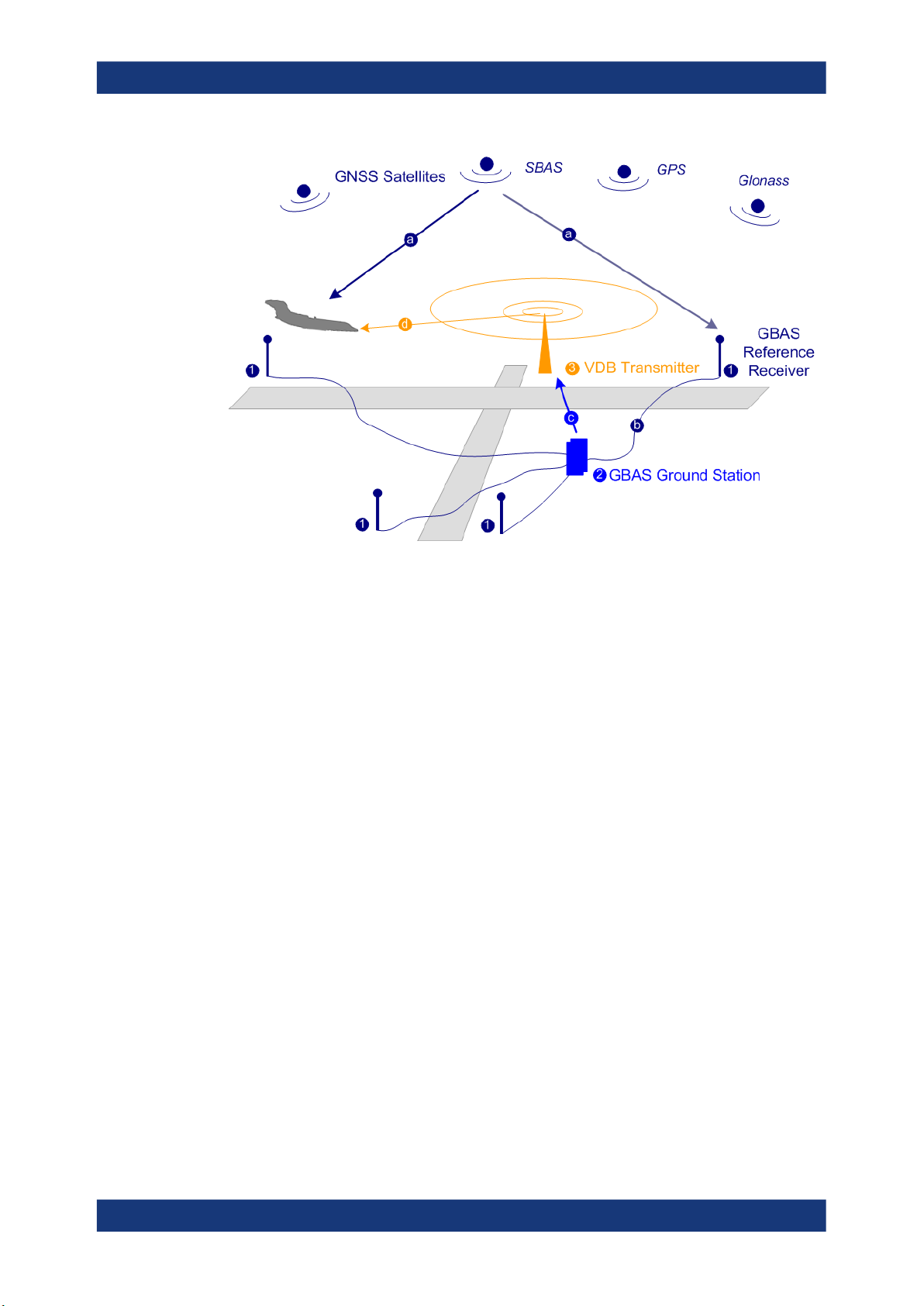
The illustration in Figure 2-1 is a simplified representation of the GBAS three main
components:
●
The GNSS satellite subsystem
●
The airborne subsystem
●
The GBAS ground subsystem
The ground equipment consists of four reference GNSS receivers at exactly defined
positions around the airport, GBAS ground station, and a VHF data broadcast transmitter (VDB).
9User Manual 1178.9690.02 ─ 08
R&S®SMW-K111
About the GBAS option
About GBAS
Figure 2-1: GBAS components and signals (simplified representation)
1 = GNSS reference receiver
2 = GBAS ground station
3 = VHF data broadcast (VDB) transmitter
a = GNSS navigation message
b = Pseudorange
c = GBAS Correction message
d = VDB signal
The GBAS GNSS reference receiver receives the GNSS navigation message, performs pseudorange measurements and transmits this information to the GBAS ground
station. The GBAS ground station determines errors in the calculated positions, adds
additional parameters and approach path information, produces a GBAS correction
message and sends it the VDB transmitter. The VDB transmitter modulates and encodes this message and broadcasts it to the airborne GBAS equipment, for example a
GBAS receiver in the airplane. The GBAS equipment in the airplane is a high-precision
multimode receiver that evaluates the message and applies corrections parameters to
improve the navigation algorithms from GPS.
This list outlines the three signals transmitted between the components which are
referred as GBAS Signal-in-Space:
●
GNSS satellite to GBAS ground subsystem navigation signal
●
GNSS satellite to GBAS airborne subsystem navigation signal
●
GBAS ground subsystem to GBAS airborne subsystem VHF data broadcast
This firmware option enables you to generate the VHF data broadcast
Carrier frequencies and frequency channels
The VHF data broadcast is defined for carrier frequencies within the range of 108.025
MHz to 117.975 MHz and carrier spacing of 25.0 kHz.
10User Manual 1178.9690.02 ─ 08
R&S®SMW-K111
About the GBAS option
About GBAS
The R&S SMW supports the whole required frequency range; you can modulate the
VHF signal on any one of these carrier frequencies. Moreover, this firmware option
supports two frequency allocation modes, a single frequency and a multiple frequency
transmission.
When you chose the frequency allocation mode, consider the following:
●
Single frequency mode is suitable to simulate the signal of up to eight VDB transmitters modulated on the same carrier frequency.
The signal calculation is fast and optimized for time sensitive applications.
This mode is also the choice if the DUT or the analyzing equipment supports single
band decoding.
●
Multi-frequency mode is suitable to allocate the VDB transmitters to up to 8 out of
11 adjacent frequency channels.
The generated signal is optimized for reduced adjacent and co-channel interference to neighboring systems. The setting time, however, increase significantly
compared to the single frequency mode.
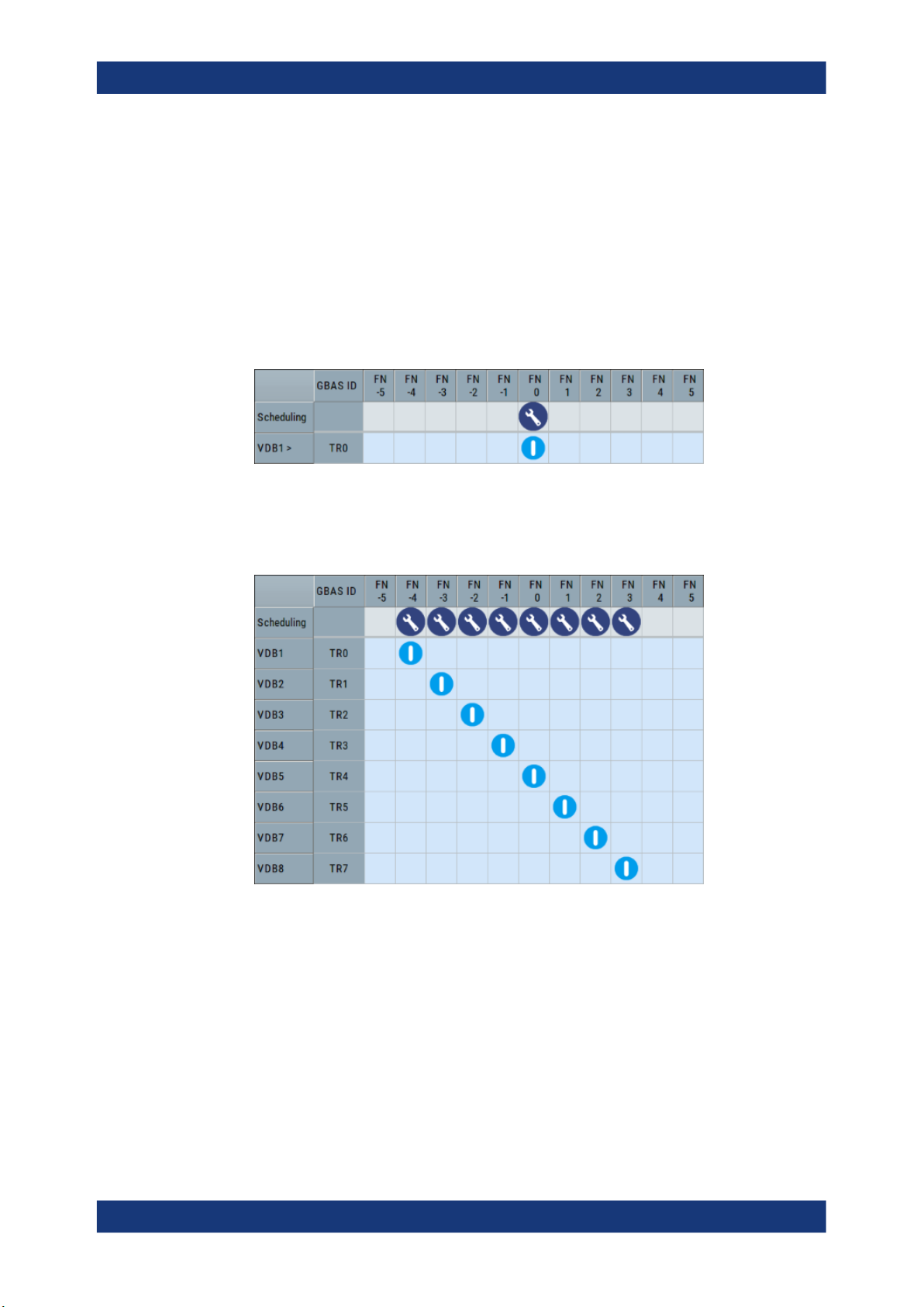
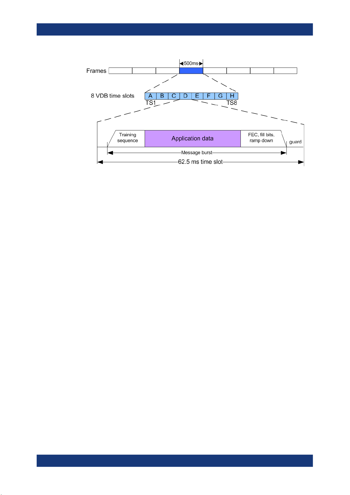
Broadcast timing structure
The broadcast is a Time Division Multiple Access (TDMA). According to the GBAS
specification RTCA DO-246D, the TDMA timing structure uses a two level hierarchy,
composed of 500 ms long frames, each divided into 8 VDB time slots (A - H), see Fig-
ure 2-2.
11User Manual 1178.9690.02 ─ 08
R&S®SMW-K111
About the GBAS option
About GBAS
Figure 2-2: TDMA timing structure (simplified representation)
A VDB time slot is the minimum resource that an individual VDB transmitter can use.
During one time slot, a VDB transmitter transmits exactly one burst.
The GBAS specification RTCA DO-246D defines the TDMA timing structure, including
timing budget of the VDB bursts, burst data contents and message encoding in great
details. The R&S SMW generates the required training sequence, encodes the message according to RTCA DO-246D and applies the D8PSK modulation automatically,
so that you can concentrate on the configuration of the mandatory application data.
Optional application data defined in RTCA DO-246D is beyond the scope of this implementation.
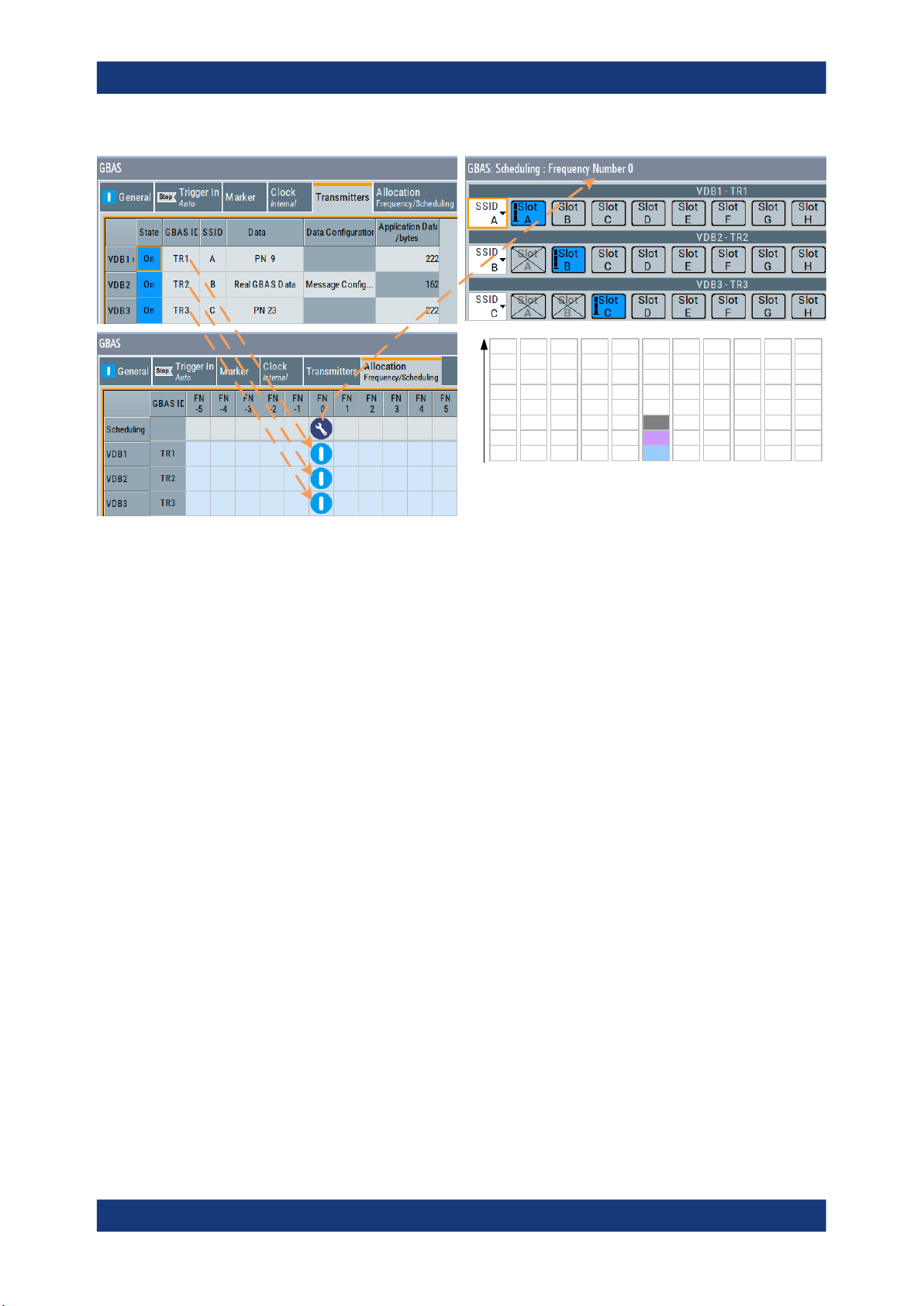
To allocate the VDB in the time domain, use the scheduling settings, see Chap-
ter 3.4.2, "Scheduling settings", on page 45.
Refer to Figure 2-3 for illustration on how a multi-frequency TDMA scheduling is performed in this implementation.
12User Manual 1178.9690.02 ─ 08
R&S®SMW-K111
About the GBAS option
About GBAS
H
H
H
H
G
G
F
Time slots
E
D
C
B
A
FN -5 FN -4 FN -3 FN -2 FN -1 FN 0 FN 1 FN 2 FN 3 FN 4 FN 5
G
F
F
E
E
D
D
C
C
B
B
A
A
H
G
G
F
F
E
E
D
D
C
C
B
B
A
A
H
G
F
E
D
VDB3
VDB2
VDB1
H
G
F
E
D
C
B
A
H
H
G
G
F
F
E
E
D
D
C
C
B
B
A
A
H
H
G
G
F
F
E
E
D
D
C
C
B
B
A
A
Figure 2-3: Example of a multi-frequency TDMA scheduling
Power settings
In the R&S SMW, the following parameters have impact on the signal power of the time
slots:
●
RF output power ("Status Bar > Level")
Defines the RMS level of the generated signal
●
Relative power per time slot ("GBAS > Allocation > VDB# > Scheduling > Slot A
to H > Power")
Sets the relative power of a VDB per time slot (Slot A to H).
●
Power generation mode ("GBAS > Gated Power Mode")
Defines the way the absolute power of a VDB per time slot is calculated.
The absolute power of a single time slot depends on the power settings of the
remaining time slots.
See Example "Calculating the power per time slot in "Gated Power Mode > Off""
on page 14 and Example "Calculating the power per time slot in "Gated Power
Mode > On"" on page 14 for explanation on how the parameter "Gated Power
Mode" influence the calculation.
13User Manual 1178.9690.02 ─ 08

R&S®SMW-K111
About the GBAS option
About GBAS
Example: Calculating the power per time slot in "Gated Power Mode > Off"
●
"Level = - 30 dBm"
●
"TS1 > State > On", relative power "TS1 > Pow(dB) = 0 dB"
●
"TS3 > State > On", relative power "TS3 > Pow(dB) = 0 dB"
●
"TS2/TS4/TS5/TS6/TS7/TS8 > State > Off"
"TS2/TS4/TS5/TS6/TS7/TS8 > Pow(dB) = -inf"
The absolute power of both scheduled time slots is P
TS1
= P
= -24 dBm.
TS3
Example: Calculating the power per time slot in "Gated Power Mode > On"
●
"Level = - 30 dBm"
●
"TS1 > State > On", relative power "TS1 > Pow(dB) = 0 dB"
●
"TS3 > State > On", relative power "TS3 > Pow(dB) = -3 dB"
●
"TS2/TS4/TS5/TS6/TS7/TS8 > State > Off"
"TS2/TS4/TS5/TS6/TS7/TS8 > Pow(dB) = -inf"
The absolute power of the scheduled time slots is:
●
P
= -30 dBm
TS1
●
P
= -33 dBm.
TS3
Supported message types
The GBAS specification RTCA DO-246D defines the following mandatory message
types. This implementation supports all required message types. Refer to Table 2-1 for
information on where to find the related settings.
Table 2-1: Overview of the required message types
Message type Description Related settings
1 Differential corrections
100 sec smoothed pseudoranges
2 GBAS-related data Chapter 3.3.2, "Message type 2 settings",
Chapter 3.3.1, "Message type 1 & 11 settings", on page 21
on page 23
14User Manual 1178.9690.02 ─ 08

R&S®SMW-K111
About the GBAS option
About GBAS
Message type Description Related settings
4 Final Approach Segment
(FAS) construction data
11 Differential corrections
Terminal Area Path (TAP)
construction data
30 sec smoothed pseudoranges
Chapter 3.3.3.2, "FAS data settings",
on page 33
Chapter 3.3.3.3, "TAP data settings",
on page 36
Chapter 3.3.1, "Message type 1 & 11 settings", on page 21
Rohde&Schwarz solution for radio analysis
If your task requires verifications and measurements of GBAS installations on the
ground and in the air, consider to use the R&S®EVS300 ILS/VOR analyzer.
This instrument is a portable level and modulation analyzer. If equipped with the
required options, it is capable to perform VHF data link measurements on GBAS and
measurements on conventional ILS ground systems and VOR systems.
15User Manual 1178.9690.02 ─ 08
R&S®SMW-K111
3 GBAS configuration and settings
3.1 General settings
GBAS configuration and settings
General settings
Access:
► Select "Baseband > GBAS".
The remote commands required to define these settings are described in Chapter 6,
"Remote-control commands", on page 62.
Settings:
● General settings......................................................................................................16
● Transmitter settings.................................................................................................19
● Message configuration settings...............................................................................21
● Allocation and frequency/scheduling settings......................................................... 43
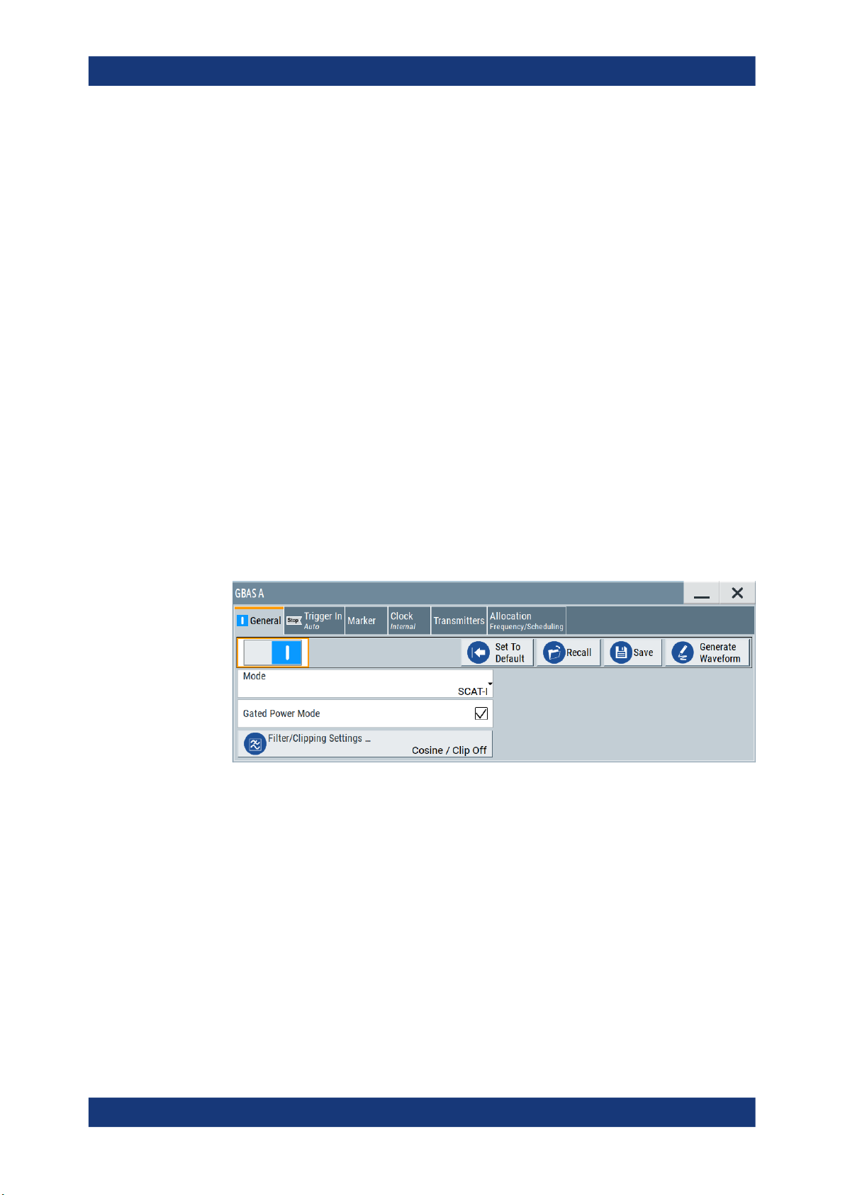
Access:
► Select "Baseband > GBAS > General".
The dialog provides access to the default, "Save/Recall" settings, general GBAS
settings and access to dialogs with further settings.
Settings:
State..............................................................................................................................16
Set to Default................................................................................................................ 17
Save/Recall...................................................................................................................17
Generate Waveform......................................................................................................17
Mode............................................................................................................................. 18
Gated Power Mode....................................................................................................... 18
Filter/Clipping Settings.................................................................................................. 18
State
Activates the GBAS standard.
16User Manual 1178.9690.02 ─ 08
R&S®SMW-K111
GBAS configuration and settings
General settings
Activation of the standard disables all the other digital standards and digital modulation
modes in the same baseband.
Remote command:
[:SOURce<hw>]:BB:GBAS:STATe on page 71
Set to Default
Calls the default settings. The values of the main parameters are listed in the following
table.
Parameter Value
State Not affected by the "Set to Default"
Mode GBAS
Gated Power Mode On
Sample Rate Variation 10.5 kHz
Filter Cosine
Clipping Off
Trigger Auto
Clock Internal
Remote command:
[:SOURce<hw>]:BB:GBAS:PRESet on page 69
Save/Recall
Accesses the "Save/Recall" dialog, that is the standard instrument function for saving
and recalling the complete dialog-related settings in a file. The provided navigation
possibilities in the dialog are self-explanatory.
The settings are saved in a file with predefined extension. You can define the filename
and the directory, in that you want to save the file.
See also, chapter "File and Data Management" in the R&S SMW user manual.
Remote command:
[:SOURce<hw>]:BB:GBAS:SETTing:CATalog? on page 69
[:SOURce<hw>]:BB:GBAS:SETTing:DELete on page 70
[:SOURce<hw>]:BB:GBAS:SETTing:LOAD on page 70
[:SOURce<hw>]:BB:GBAS:SETTing:STORe on page 70
Generate Waveform
With enabled signal generation, triggers the instrument to save the current settings of
an arbitrary waveform signal in a waveform file with predefined extension *.wv. You
can define the filename and the directory, in that you want to save the file.
Using the ARB modulation source, you can play back waveform files and/or process
the file to generate multi-carrier or multi-segment signals.
Remote command:
[:SOURce<hw>]:BB:GBAS:WAVeform:CREate on page 71
17User Manual 1178.9690.02 ─ 08

R&S®SMW-K111
GBAS configuration and settings
General settings
Mode
Enables header information for the set GBAS mode, i.e. the corresponding landing
system.
The modulation and TDMA schemes of both systems are identical. Table 3-1 lists the
set header bytes for each landing system.
Table 3-1: Header start byte
Landing system Header start byte
GBAS (LAAS) 0xAAh
SCAT-I 0x99h
"GBAS"
Enables GBAS (LAAS) header information conforming with specification RTCA DO-246D.
"SCAT-I"
Enables SCAT-I header information conforming with specification
RTCA DO-217.
Remote command:
[:SOURce<hw>]:BB:GBAS:MODE on page 69
Gated Power Mode
Activates gated power mode, see "Power settings" on page 13.
Remote command:
[:SOURce<hw>]:BB:GBAS:GPOW on page 68
Filter/Clipping Settings...
Accesses the dialog for setting baseband filtering, clipping and modulation, see Chap-
ter 4.1, "Filter/clipping settings", on page 49.
18User Manual 1178.9690.02 ─ 08
R&S®SMW-K111
3.2 Transmitter settings
GBAS configuration and settings
Transmitter settings
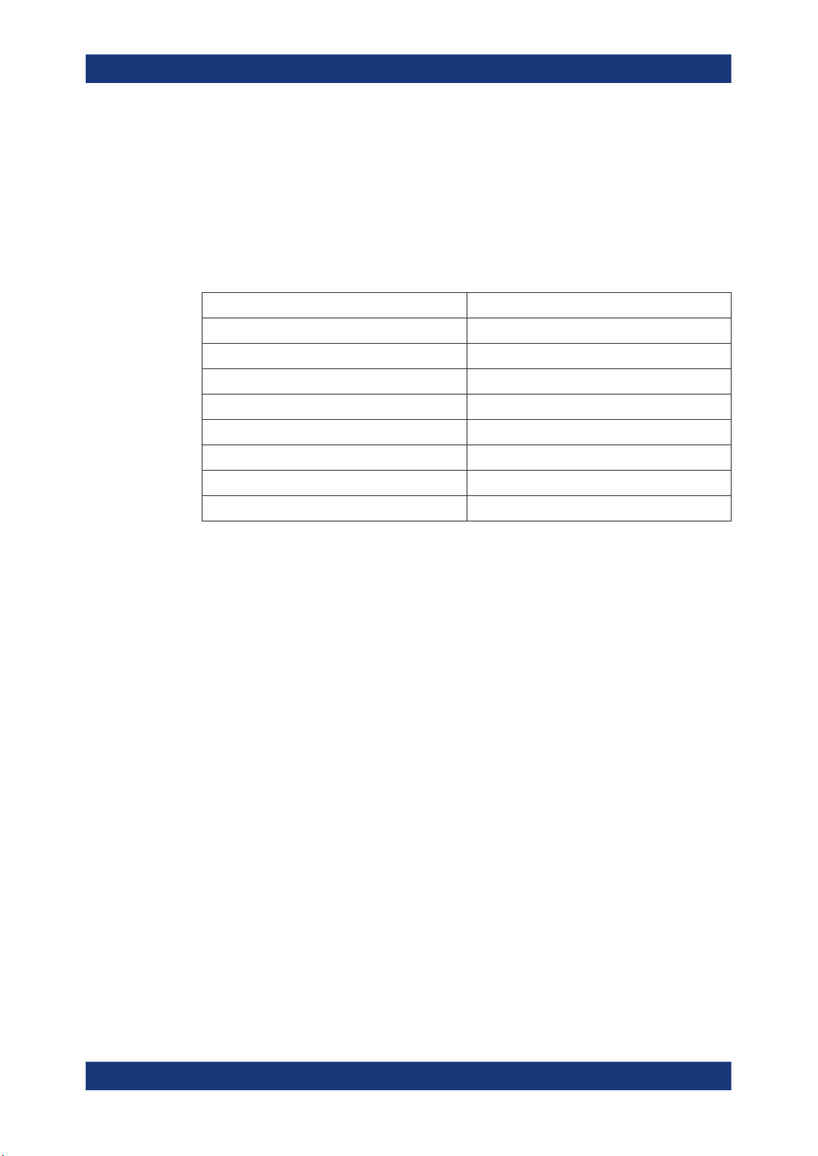
Access:
► Select "GBAS > Transmitters".
The dialog comprises the settings, necessary to configure the VHF Data Broadcast
(VDB) signals.
Settings
State..............................................................................................................................19
GBAS ID........................................................................................................................19
SSID..............................................................................................................................20
Data/Data Configuration................................................................................................20
App. Data Length/bytes.................................................................................................20
Number of Frames........................................................................................................ 21
Append, Insert, Delete.................................................................................................. 21
State
Enables the selected VHF Data Broadcast (VDB) transmitter.
Remote command:
[:SOURce<hw>]:BB:GBAS:VDB<ch>:STATe on page 73
GBAS ID
Sets the GBAS ID, that is a four-character (24-bit) alphanumeric field that identifies the
ground station broadcasting the message. Permitted are capital letter, numbers and
"space".
To identify a ground station, the airborne receiver examines the combination of the
GBAS ID and the SSID.
Remote command:
[:SOURce<hw>]:BB:GBAS:VDB<ch>:GID on page 73
19User Manual 1178.9690.02 ─ 08

R&S®SMW-K111
GBAS configuration and settings
Transmitter settings
SSID
Sets the station slot identifier SSID/RSID of the ground station.
According to RTCA DO-246D, the SSID is a numeric value from 0 to 7, corresponding
to the letter designation (A through H) of the first time slot assigned to a particular
ground reference station, where slot A = 0 and slot H = 7. All messages in all time slots
employed by a particular ground station use the same SSID.
To identify a ground station, the airborne receiver examines the combination of the
GBAS ID and the SSID.
Remote command:
[:SOURce<hw>]:BB:GBAS:VDB<ch>:SSID on page 73
Data/Data Configuration
Selects the data source for the VDB.
The following standard data sources are available:
●
"All 0, All 1"
An internally generated sequence containing 0 data or 1 data.
●
"PNxx"
An internally generated pseudo-random noise sequence.
●
"Pattern"
An internally generated sequence according to a bit pattern.
Use the "Pattern" box to define the bit pattern.
●
"Data List/Select DList"
A binary data from a data list, internally or externally generated.
Select "Select DList" to access the standard "Select List" dialog.
– Select the "Select Data List > navigate to the list file *.dm_iqd > Select" to
select an existing data list.
– Use the "New" and "Edit" functions to create internally new data list or to edit
an existing one.
– Use the standard "File Manager" function to transfer external data lists to the
instrument.
See also:
●
Section "Modulation Data" in the R&S SMW user manual.
●
Section "File and Data Management" in the R&S SMW user manual.
●
Section "Data List Editor" in the R&S SMW user manual
"Real GBAS Data"
Enables you to configure the content of the GBAS messages.
Select "Data Config > Message Config..." to access the provided settings.
Remote command:
[:SOURce<hw>]:BB:GBAS:VDB<ch>:DATA on page 74
[:SOURce<hw>]:BB:GBAS:VDB<ch>:DATA:DSELection on page 74
[:SOURce<hw>]:BB:GBAS:VDB<ch>:DATA:PATTern on page 75
App. Data Length/bytes
Sets the application data length.
For "Data/Data Configuration > Real GBAS Data", the value of the application data
length is not variable but is automatically set and calculated.
20User Manual 1178.9690.02 ─ 08

R&S®SMW-K111
GBAS configuration and settings
Message configuration settings
Remote command:
[:SOURce<hw>]:BB:GBAS:VDB<ch>:DLENgth on page 74
Number of Frames
Displays the automatically calculated number of frames of the selected VDB.
Remote command:
[:SOURce<hw>]:BB:GBAS:NOFRames? on page 72
Append, Insert, Delete
You can configure up to 8 VDB transmitters. Use the appropriate general functions:
"Append"
Remote command:
[:SOURce<hw>]:BB:GBAS:VDB:APPend on page 72
Adds a new row in the table of VDB transmitters.
"Insert"
Remote command:
[:SOURce<hw>]:BB:GBAS:VDB<ch>:INSert on page 72
"Delete"
Remote command:
[:SOURce<hw>]:BB:GBAS:VDB<ch>:DELete on page 72
Adds a new row above the currently selected one.
Deletes the selected row.
3.3 Message configuration settings
Access:
1. Select "GBAS > Transmitters".
2. Select "VDB# > Data > Real Data".
3. Select "Data Configiguration > Message Config...".
The dialog "VDB#: Message Configuration" provides settings to configure message
types 1, 2, 4 and 11.
Settings
● Message type 1 & 11 settings................................................................................. 21
● Message type 2 settings......................................................................................... 23
● Message type 4 settings......................................................................................... 31
3.3.1 Message type 1 & 11 settings
Differential GNSS is an approach that uses known GNSS reference locations to determine channel correction parameters. The retrieved information is transmitted to other
GNSS receivers to increase the accuracy of their position information.
21User Manual 1178.9690.02 ─ 08
R&S®SMW-K111
GBAS configuration and settings
Message configuration settings
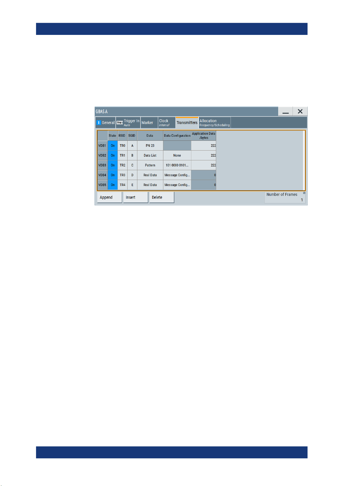
Access:
1. Select "Data Configuration > Message Config...", see Chapter 3.3, "Message con-
figuration settings", on page 21.
2. Select "VDB#: Message Configuration > Message Type 1 & 11"
The dialog provides settings to manage GBAS differential data.
For step-by-step description on how to load GBAS differential data, see Chapter 5.1,
"Loading differential GBAS data", on page 61.
Settings
Message Type 1............................................................................................................22
Message Type 11..........................................................................................................22
Differential Corrections File ..........................................................................................22
Predefined Files............................................................................................................ 23
Message Type 1
Activates the use of message type 1, differential GPS corrections.
Remote command:
[:SOURce<hw>]:BB:GBAS:VDB<ch>:MCONfig:DG:M1STate on page 78
Message Type 11
Activates the use of the message type 11, C/A-Code L1, L2 delta corrections.
Remote command:
[:SOURce<hw>]:BB:GBAS:VDB<ch>:MCONfig:DG:M11State on page 78
Differential Corrections File ...
Accesses the "Proprietary File" dialog to select a file containing differential GBAS information.
The differential GBAS file must have the extension *.rs_gbas and file format as
described in Chapter A.2, "GBAS differential file format", on page 117.
The differential SCAT-I file must have the extension *.rs_scat and file format as
described in Chapter A.3, "SCAT-I differential file format", on page 120.
Select "Predefined Files" to load a predefined file.
Remote command:
For "Mode > GBAS":
[:SOURce<hw>]:BB:GBAS:VDB<ch>:MCONfig:DG:FILE? on page 81
[:SOURce<hw>]:BB:GBAS:VDB<ch>:MCONfig:DG:USER:CATalog? on page 80
[:SOURce<hw>]:BB:GBAS:VDB<ch>:MCONfig:DG:USER:FILE on page 80
22User Manual 1178.9690.02 ─ 08
R&S®SMW-K111
GBAS configuration and settings
Message configuration settings
For "Mode > SCAT-I":
[:SOURce<hw>]:BB:GBAS:VDB<ch>:MCONfig:DG:SFILe? on page 81
[:SOURce<hw>]:BB:GBAS:VDB<ch>:MCONfig:DG:SUSer:CATalog on page 80
[:SOURce<hw>]:BB:GBAS:VDB<ch>:MCONfig:DG:SUSer:FILE on page 79
Predefined Files
Accesses a list with predefined files.
Remote command:
For "Mode > GBAS":
[:SOURce<hw>]:BB:GBAS:VDB<ch>:MCONfig:DG:PREDefined:CATalog?
on page 80
[:SOURce<hw>]:BB:GBAS:VDB<ch>:MCONfig:DG:PREDefined:FILE
on page 80
For "Mode > SCAT-I":
[:SOURce<hw>]:BB:GBAS:VDB<ch>:MCONfig:DG:SPRedefined:CATalog
on page 80
[:SOURce<hw>]:BB:GBAS:VDB<ch>:MCONfig:DG:SPRedefined:FILE
on page 79
For waypoint files:
[:SOURce<hw>]:BB:GBAS:VDB<ch>:MCONfig:WAYPoint:PREDefined:
CATalog? on page 105
[:SOURce<hw>]:BB:GBAS:VDB<ch>:MCONfig:WAYPoint:PREDefined:FILE
on page 105
3.3.2 Message type 2 settings
Access:
1. Select "Data Configuration > Message Config...", see Chapter 3.3, "Message con-
figuration settings", on page 21.
2. Select "VDB#: Message Configuration > Message Type 2"
23User Manual 1178.9690.02 ─ 08

R&S®SMW-K111
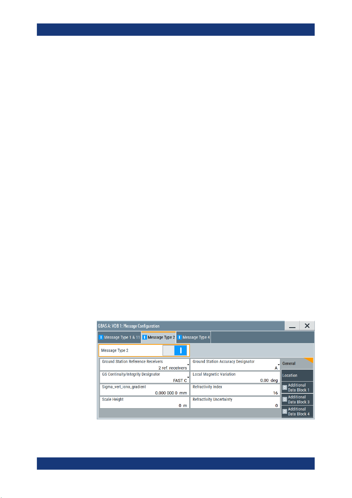
3.3.2.1 General settings
GBAS configuration and settings
Message configuration settings
The dialog provides settings to configure message type 2 parameters according to
RTCA DO-246D, Table 2.14.
Message type 2 carries information on the exact location and other GBAS-related
parameters.
Settings
● General settings......................................................................................................24
● Location settings..................................................................................................... 26
● Additional data block 1 settings...............................................................................27
● Additional data block 3 settings...............................................................................29
● Additional data block 4 settings...............................................................................30
Access:
1. Select "VDB#: Message Configuration > Message Type 2 > General Settings".
2. Select "Message Type 2 > On"
The dialog provides general settings to configure message type 2 parameter
according to RTCA DO-246D, Table 2.14.
Settings
Message Type 2............................................................................................................24
Ground Station Reference Receivers........................................................................... 24
Ground Station Accuracy Designator............................................................................25
GS Continuity/Integrity Designator................................................................................25
Local Magnetic Variation............................................................................................... 25
Sigma_vert_iono_gradient............................................................................................ 25
Refractivity Index...........................................................................................................25
Scale Height..................................................................................................................25
Refractivity Uncertainty................................................................................................. 25
Message Type 2
Enables you to configure the parameters of message type 2, according to RTCA
DO-246D, Table 2.14.
Remote command:
[:SOURce<hw>]:BB:GBAS:VDB<ch>:MCONfig:MT2State on page 82
Ground Station Reference Receivers
Selects the number of the GNSS reference receivers installed in this system.
Remote command:
[:SOURce<hw>]:BB:GBAS:VDB<ch>:MCONfig:GSRReceivers on page 83
24User Manual 1178.9690.02 ─ 08

R&S®SMW-K111
GBAS configuration and settings
Message configuration settings
Ground Station Accuracy Designator
Selects the letter designator indicating the minimum signal-in-space accuracy performance provided by the ground station.
Remote command:
[:SOURce<hw>]:BB:GBAS:VDB<ch>:MCONfig:GSADesignator on page 83
GS Continuity/Integrity Designator
Selects the numerical designator that indicates the operational status of GBAS.
Remote command:
[:SOURce<hw>]:BB:GBAS:VDB<ch>:MCONfig:GCID on page 83
Local Magnetic Variation
Sets the published local magnetic variation at the differential reference point. A positive
value represents an east variation (clockwise from true north).
Remote command:
[:SOURce<hw>]:BB:GBAS:VDB<ch>:MCONfig:LMVariation on page 84
Sigma_vert_iono_gradient
Sets the parameter σ
vert_iono_gradient
, that is the standard deviation of a normal distribu-
tion associated with the residual ionospheric uncertainty due to spatial decorrelation.
Remote command:
[:SOURce<hw>]:BB:GBAS:VDB<ch>:MCONfig:SVIGradient on page 85
Refractivity Index
Sets the estimated tropospheric refractivity index NR at the reference point.
Remote command:
[:SOURce<hw>]:BB:GBAS:VDB<ch>:MCONfig:RFINdex on page 84
Scale Height
Sets the parameter scale height (h0), used for scaling the tropospheric refractivity as a
function of differential altitude.
Remote command:
[:SOURce<hw>]:BB:GBAS:VDB<ch>:MCONfig:SHEight on page 85
Refractivity Uncertainty
Sets the parameter σN, that is the standard deviation of a normal distribution associated with the residual tropospheric uncertainty.
Remote command:
[:SOURce<hw>]:BB:GBAS:VDB<ch>:MCONfig:RUNCertainty on page 84
25User Manual 1178.9690.02 ─ 08

R&S®SMW-K111
3.3.2.2 Location settings
GBAS configuration and settings
Message configuration settings
Access:
► Select "VDB#: Message Configuration > Message Type 2 > Location Settings".
The dialog provides location settings to configure message type 2 parameter
according to RTCA DO-246D, Table 2.14.
Settings
Reference Location Configuration.................................................................................26
Reference Location Configuration
The coordinates of the ground station reference point are defined in WGS84 coordinates. In this coordinate system, a location is identified by three coordinates, the altitude, the latitude and the longitude. The last two can be displayed in decimal or DMS
format. Use the parameter "Position Format" to select the display format.
Table 3-2: Reference location configuration
Parameter Description
"Position Format" Sets the format in which the Latitude and Longitude are displayed.
"Altitude" Sets the altitude of the ground station reference point, that is the height above
●
"DEG:MIN:SEC"
The display format is Degree:Minute:Second and Direction, i.e.
XX°XX'XX.XX" Direction, where direction can be North/South and
East/West.
●
"Decimal Degree"
The display format is decimal degree, i.e. +/-XX.XXXXX°, where "+"
indicates North and East and "-" indicates South and West.
the ellipsoid (HAE) altitude.
"Latitude" Sets the latitude of the ground station reference point.
"Longitude" Sets the longitude of the ground station reference point.
26User Manual 1178.9690.02 ─ 08
R&S®SMW-K111
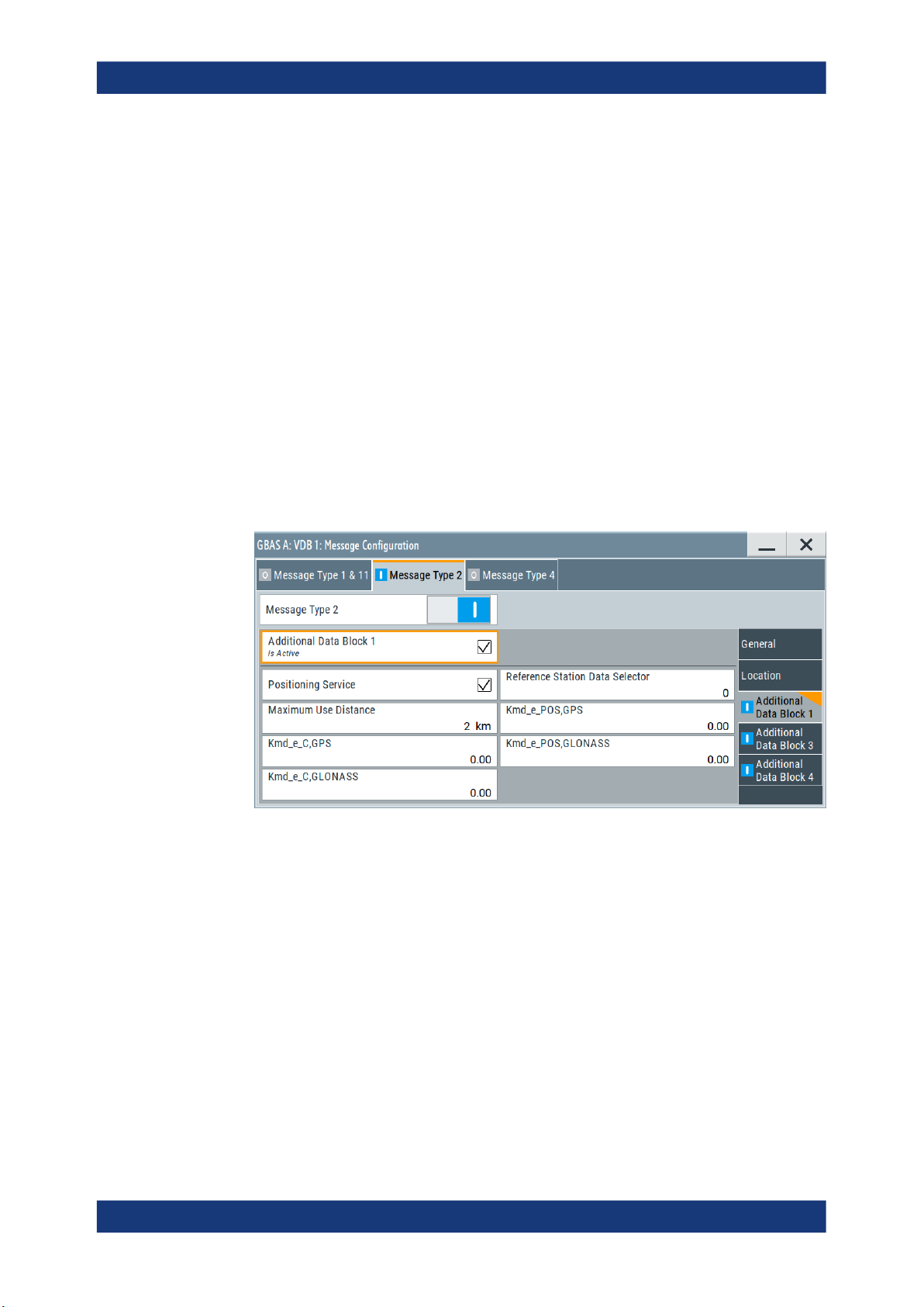
3.3.2.3 Additional data block 1 settings
GBAS configuration and settings
Message configuration settings
Remote command:
To specify the position format:
[:SOURce<hw>]:BB:GBAS:VDB<ch>:MCONfig:LOCation:COORdinates:
FORMat on page 89
To enter the coordinates in Degree:Minute:Second format:
[:SOURce<hw>]:BB:GBAS:VDB<ch>:MCONfig:LOCation:COORdinates:DMS
on page 88
To enter the coordinates in decimal degree format
[:SOURce<hw>]:BB:GBAS:VDB<ch>:MCONfig:LOCation:COORdinates:
DECimal on page 88
Access:
► Select "VDB#: Message Configuration > Message Type 2 > Additional Data Block
1".
The dialog provides additional data block 1 settings to configure message type 2
parameter according to RTCA DO-246D, Table 2.14.
Settings
Additional Data Block 1.................................................................................................27
Positioning Service........................................................................................................28
Reference Station Data Selector...................................................................................28
Maximum User Distance...............................................................................................28
Kmd_e_C,GPS/Kmd_e_C,GLONASS.......................................................................... 28
Kmd_e_POS,GPS/Kmd_e_POS,GLONASS................................................................ 28
Additional Data Block 1
Enables you to configure the additional data block 1.
Remote command:
[:SOURce<hw>]:BB:GBAS:VDB<ch>:MCONfig:ADB1:STATe on page 82
27User Manual 1178.9690.02 ─ 08

R&S®SMW-K111
GBAS configuration and settings
Message configuration settings
Positioning Service
Selects if the GBAS positioning service is supported.
Remote command:
[:SOURce<hw>]:BB:GBAS:VDB<ch>:MCONfig:PSERvice:STATe on page 86
Reference Station Data Selector
Requires "Positioning Service > On".
Sets the numerical identifier for selecting the ground subsystem.
Remote command:
[:SOURce<hw>]:BB:GBAS:VDB<ch>:MCONfig:RSDSelector on page 86
Maximum User Distance
Sets the maximum distance from the reference point for which the integrity is assured.
Remote command:
[:SOURce<hw>]:BB:GBAS:VDB<ch>:MCONfig:MUDistance on page 86
Kmd_e_C,GPS/Kmd_e_C,GLONASS
Sets the ephemeris missed detection parameter (Kmd_e), category I precision
approach and approach with vertical guidance (APV). This is a multiplier considered
when calculating the ephemeris error position bound for the category I precision
approach and APV. It is derived from the probability that a detection is missed because
of an ephemeris error in a GPS/GLONASS satellite.
Remote command:
[:SOURce<hw>]:BB:GBAS:VDB<ch>:MCONfig:KCGLonass on page 85
[:SOURce<hw>]:BB:GBAS:VDB<ch>:MCONfig:KCGPs on page 85
Kmd_e_POS,GPS/Kmd_e_POS,GLONASS
Sets the ephemeris missed detection parameter (Kmd_e), GBAS positioning service.
This is a multiplier considered when calculating the ephemeris error position bound for
the GBAS positioning. It is derived from the probability that a detection is missed
because of an ephemeris error in a GPS/GLONASS satellite.
Remote command:
[:SOURce<hw>]:BB:GBAS:VDB<ch>:MCONfig:KPGLonass on page 86
[:SOURce<hw>]:BB:GBAS:VDB<ch>:MCONfig:KPGPs on page 86
28User Manual 1178.9690.02 ─ 08
R&S®SMW-K111
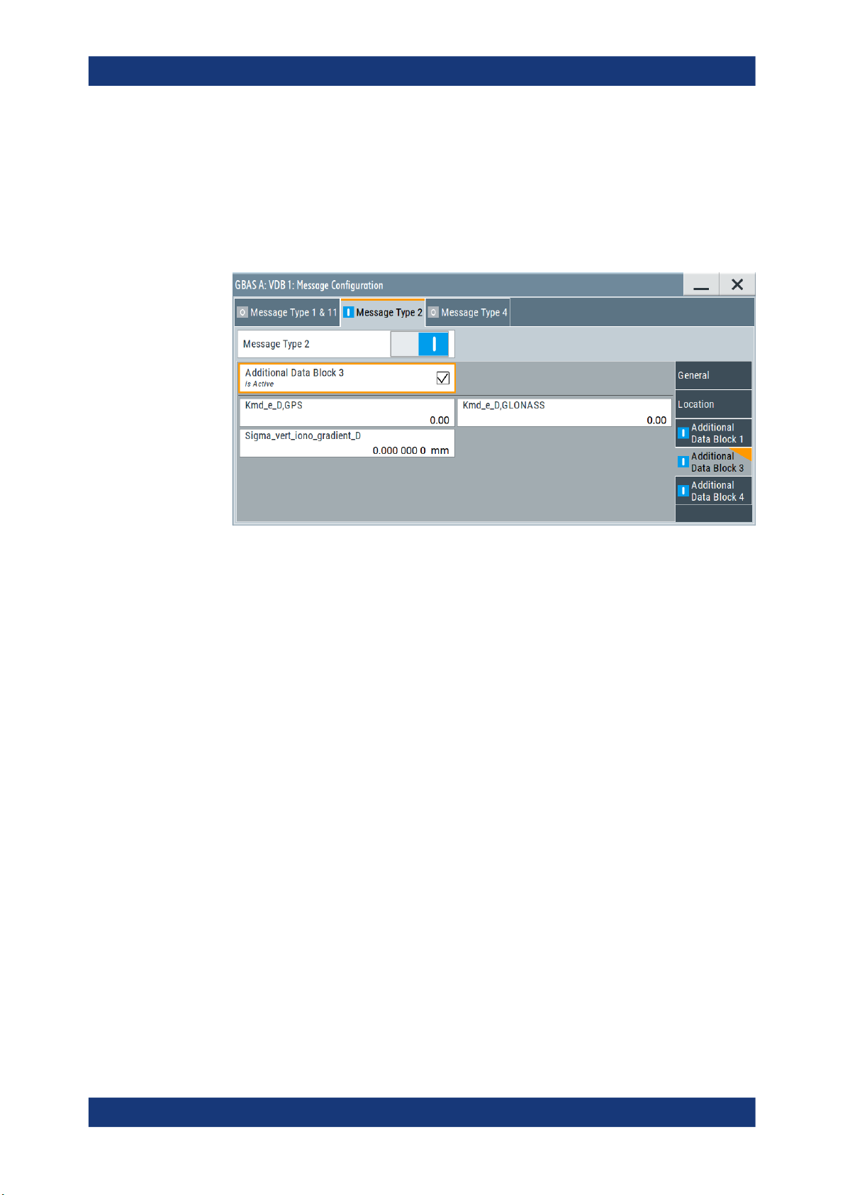
3.3.2.4 Additional data block 3 settings
GBAS configuration and settings
Message configuration settings
Access:
► Select "VDB#: Message Configuration > Message Type 2 > Additional Data Block
3".
The dialog provides additional data block 3 settings to configure message type 2
parameter according to RTCA DO-246D, Table 2.14.
Settings
Additional Data Block 3.................................................................................................29
Kmd_e_D,GPS/Kmd_e_D,GLONASS.......................................................................... 29
Sigma_vert_iono_gradient_D........................................................................................29
Additional Data Block 3
Enables you to configure the parameters of the additional block 3, containing the
GBAS approach service type (GAST) D parameters.
Remote command:
[:SOURce<hw>]:BB:GBAS:VDB<ch>:MCONfig:ADB3:STATe on page 82
Kmd_e_D,GPS/Kmd_e_D,GLONASS
Sets the ephemeris missed detection parameter (Kmd_e), GAST D. This is a multiplier
considered when calculating the ephemeris error position bound for GAST D. It is
derived from the probability that a detection is missed because of an ephemeris error
in a GPS/GLONASS satellite.
Remote command:
[:SOURce<hw>]:BB:GBAS:VDB<ch>:MCONfig:KDGLonass on page 87
[:SOURce<hw>]:BB:GBAS:VDB<ch>:MCONfig:KDGPs on page 87
Sigma_vert_iono_gradient_D
Sets the standard deviation of a normal distribution connected to the residual ionospheric uncertainty which is caused by spatial decorrelation.
29User Manual 1178.9690.02 ─ 08
R&S®SMW-K111
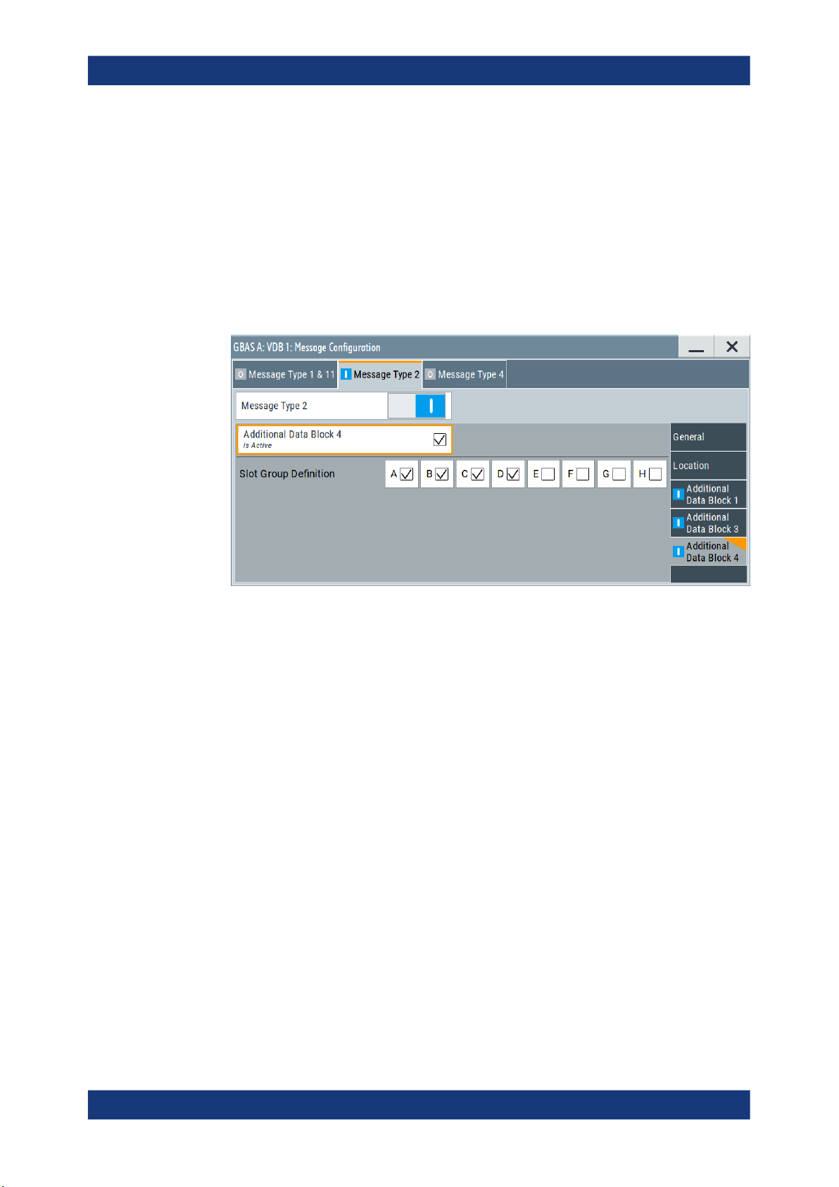
3.3.2.5 Additional data block 4 settings
GBAS configuration and settings
Message configuration settings
Remote command:
[:SOURce<hw>]:BB:GBAS:VDB<ch>:MCONfig:SVID on page 87
Access:
► Select "VDB#: Message Configuration > Message Type 2 > Additional Data Block
4".
The dialog provides additional data block 4 settings to configure message type 2
parameter according to RTCA DO-246D, Table 2.14.
Settings
Additional Data Block 4.................................................................................................30
Slot Group Definition.....................................................................................................30
Additional Data Block 4
Enables you to configure the parameters of the additional block 4, containing the VDB
authentication parameters.
Remote command:
[:SOURce<hw>]:BB:GBAS:VDB<ch>:MCONfig:ADB4:STATe on page 83
Slot Group Definition
Specifies which slots are used by the ground station. You can activate slots "A" to "H".
Remote command:
[:SOURce<hw>]:BB:GBAS:VDB<ch>:MCONfig:SGDefinition:A:STATe
on page 87
[:SOURce<hw>]:BB:GBAS:VDB<ch>:MCONfig:SGDefinition:B:STATe
on page 87
[:SOURce<hw>]:BB:GBAS:VDB<ch>:MCONfig:SGDefinition:C:STATe
on page 87
30User Manual 1178.9690.02 ─ 08