

Rohde&Schwarz R&S®SMW200A Frontend Control user manual User Manual

R&S®SMW-K553
Frontend Control
User Manual
(;ÝZX2)
1179424002
Version 03

This document describes the following software options:
●
R&S®SMW-K553 Frontend Control (1414.6758.xx)
© 2022 Rohde & Schwarz GmbH & Co. KG
Muehldorfstr. 15, 81671 Muenchen, Germany
Phone: +49 89 41 29 - 0
Email: info@rohde-schwarz.com
Internet: www.rohde-schwarz.com
Subject to change – data without tolerance limits is not binding.
R&S® is a registered trademark of Rohde & Schwarz GmbH & Co. KG.
Trade names are trademarks of the owners.
1179.4240.02 | Version 03 | R&S®SMW-K553
The following abbreviations are used throughout this manual: R&S®SMW200A is abbreviated as R&S SMW, R&S®FE is abbreviated
as R&S FE and R&S®FSV3000 and the R&S®FSVA3000 are abbreviated as R&S FSV/A. The license types 02/03/07/11/12/13/16
are abbreviated as xx.

R&S®SMW-K553
1 Welcome to the Frontend Control option............................................ 5
1.1 Key features...................................................................................................................5
1.2 Accessing the Frontend Control dialog......................................................................5
1.3 What's new.....................................................................................................................6
1.4 Documentation overview..............................................................................................6
1.4.1 Getting started manual....................................................................................................6
1.4.2 User manuals and help................................................................................................... 6
1.4.3 Tutorials...........................................................................................................................7
1.4.4 Service manual............................................................................................................... 7
1.4.5 Instrument security procedures.......................................................................................7
1.4.6 Printed safety instructions............................................................................................... 7
Contents
Contents
1.4.7 Data sheets and brochures............................................................................................. 7
1.4.8 Release notes and open source acknowledgment (OSA).............................................. 7
1.4.9 Application notes, application cards, white papers, etc...................................................8
1.5 Scope............................................................................................................................. 8
1.6 Notes on screenshots...................................................................................................8
2 About the Frontend Control option...................................................... 9
2.1 Required options...........................................................................................................9
2.2 External frontend basics.............................................................................................. 9
2.3 Test setup.....................................................................................................................10
3 Operating external frontends..............................................................12
3.1 Connecting external frontends.................................................................................. 12
3.2 Controlling external frontends...................................................................................14
3.3 Generating RF output signals....................................................................................19
3.4 Updating the firmware................................................................................................ 19
4 External frontend configuration and settings................................... 22
4.1 External RF settings................................................................................................... 22
4.2 RF frontend settings................................................................................................... 22
4.2.1 General settings............................................................................................................ 23
4.2.2 Versions and options information..................................................................................26
3User Manual 1179.4240.02 ─ 03

R&S®SMW-K553
4.2.3 Attenuator settings........................................................................................................ 27
4.2.4 Cable correction settings...............................................................................................28
4.2.5 Network settings............................................................................................................30
5 Troubleshooting Frontend Control.....................................................32
6 Remote control commands.................................................................34
6.1 SOURce:EFRontend subsystem................................................................................35
6.2 CALibration subsystem..............................................................................................44
Contents
List of commands................................................................................ 46
Index......................................................................................................47
4User Manual 1179.4240.02 ─ 03

R&S®SMW-K553
1 Welcome to the Frontend Control option
Welcome to the Frontend Control option
Accessing the Frontend Control dialog
The R&S SMW-K553 option Frontend Control is a firmware application that allows you
to configure and calibrate external frontends connected to the R&S SMW.
This user manual contains a description of the functionality that the application provides, including remote control operation.
All functions not discussed in this manual are the same as in the base unit and are
described in the R&S SMW user manual. The latest version is available at:
www.rohde-schwarz.com/manual/SMW200A
Installation
You can find detailed installation instructions in the delivery of the option or in the
R&S SMW service manual.
1.1 Key features
The R&S SMW-K553 features:
●
Configuring external frontends, including setting the output RF level and RF frequency of the connected external frontend at R&S SMW taskbar
●
Correcting frequency responses of the external frontend
●
Correcting cable losses within the connecting cable between external frontend and
R&S SMW
1.2 Accessing the Frontend Control dialog
Accessing the functionality requires, that an external frontend is connected to the
R&S SMW. You need connections for control of the external frontend (LAN), for the reference signal and for the IF signal.
How to: Chapter 3, "Operating external frontends", on page 12
To open the dialog with Frontend Control settings
► Select one of the following in the block diagram:
● Click the "FE ..." icon to the right of the "RF A/RF B" block.
For example, the icon displays "FE44S" for an R&S FE44S connected to the
R&S SMW.
● Select "RF A/RF B" > "RF Frontend" > "Frontend Device".
A dialog box opens to configure external frontend settings.
5User Manual 1179.4240.02 ─ 03

R&S®SMW-K553
1.3 What's new
Welcome to the Frontend Control option
Documentation overview
To output the upconverted IF signal from the R&S SMW at the external frontend, select
"RF A/RF B > On".
This manual describes firmware version FW 5.00.166.xx and later of the
R&S®SMW200A.
Compared to the previous version, it provides the new features listed below:
●
Frequency band configuration mode configured at the external frontend, see
"Mode" on page 25.
●
Intermediate frequency value and sideband display, see "Intermediate Frequency"
on page 24.
●
Firmware update of the microcontroller of the external frontend, see Chapter 3.4,
"Updating the firmware", on page 19.
●
Editorial changes
1.4 Documentation overview
This section provides an overview of the R&S SMW user documentation. Unless specified otherwise, you find the documents on the R&S SMW product page at:
www.rohde-schwarz.com/manual/smw200a
1.4.1 Getting started manual
Introduces the R&S SMW and describes how to set up and start working with the product. Includes basic operations, typical measurement examples, and general information, e.g. safety instructions, etc. A printed version is delivered with the instrument.
1.4.2 User manuals and help
Separate manuals for the base unit and the software options are provided for download:
●
Base unit manual
Contains the description of all instrument modes and functions. It also provides an
introduction to remote control, a complete description of the remote control commands with programming examples, and information on maintenance, instrument
interfaces and error messages. Includes the contents of the getting started manual.
●
Software option manual
Contains the description of the specific functions of an option. Basic information on
operating the R&S SMW is not included.
6User Manual 1179.4240.02 ─ 03

R&S®SMW-K553
1.4.3 Tutorials
1.4.4 Service manual
Welcome to the Frontend Control option
Documentation overview
The contents of the user manuals are available as help in the R&S SMW. The help
offers quick, context-sensitive access to the complete information for the base unit and
the software options.
All user manuals are also available for download or for immediate display on the Internet.
The R&S SMW provides interactive examples and demonstrations on operating the
instrument in form of tutorials. A set of tutorials is available directly on the instrument.
Describes the performance test for checking compliance with rated specifications, firmware update, troubleshooting, adjustments, installing options and maintenance.
The service manual is available for registered users on the global Rohde & Schwarz
information system (GLORIS):
https://gloris.rohde-schwarz.com
1.4.5 Instrument security procedures
Deals with security issues when working with the R&S SMW in secure areas. It is available for download on the Internet.
1.4.6 Printed safety instructions
Provides safety information in many languages. The printed document is delivered with
the product.
1.4.7 Data sheets and brochures
The data sheet contains the technical specifications of the R&S SMW. It also lists the
options and their order numbers and optional accessories.
The brochure provides an overview of the instrument and deals with the specific characteristics.
See www.rohde-schwarz.com/brochure-datasheet/smw200a
1.4.8 Release notes and open source acknowledgment (OSA)
The release notes list new features, improvements and known issues of the current
firmware version, and describe the firmware installation.
7User Manual 1179.4240.02 ─ 03

R&S®SMW-K553
1.4.9 Application notes, application cards, white papers, etc.
1.5 Scope
Welcome to the Frontend Control option
Notes on screenshots
The open-source acknowledgment document provides verbatim license texts of the
used open source software.
See www.rohde-schwarz.com/firmware/smw200a
These documents deal with special applications or background information on particular topics.
See www.rohde-schwarz.com/application/smw200a and www.rohde-schwarz.com/
manual/smw200a
Tasks (in manual or remote operation) that are also performed in the base unit in the
same way are not described here.
In particular, it includes:
●
Managing settings and data lists, like saving and loading settings, creating and
accessing data lists, or accessing files in a particular directory.
●
Information on regular trigger, marker and clock signals and filter settings, if appropriate.
●
General instrument configuration, such as checking the system configuration, configuring networks and remote operation
●
Using the common status registers
For a description of such tasks, see the R&S SMW user manual.
1.6 Notes on screenshots
When describing the functions of the product, we use sample screenshots. These
screenshots are meant to illustrate as many as possible of the provided functions and
possible interdependencies between parameters. The shown values may not represent
realistic usage scenarios.
The screenshots usually show a fully equipped product, that is: with all options installed. Thus, some functions shown in the screenshots may not be available in your particular product configuration.
8User Manual 1179.4240.02 ─ 03

R&S®SMW-K553
2 About the Frontend Control option
2.1 Required options
About the Frontend Control option
External frontend basics
This chapter provides information on required options and basics for controlling external frontends.
The equipment layout for external frontend operation includes:
●
Standard or wideband baseband generator (R&S SMW-B10/-B9)
●
Baseband main module (R&S SMW-B13/-B13T) or wideband baseband main module (R&S SMW-B13XT)
●
Frequency option:
– RF A: R&S SMW-B106/B1006 or higher
– RF B: R&S SMW-B206/B2006 or higher
●
Frontend control option R&S SMW-K553
For more information, see data sheet.
2.2 External frontend basics
Due to the physical dimensions of modern signal generators, long RF cables between
the DUT and the signal generator are often necessary in complex test setups. When
measuring high frequency signals, the long RF cable can lead to unwanted loss.
An external frontend with smaller physical dimensions allows for testing closer to the
DUT. The test signal is transferred (Tx mode) from the R&S SMW to the external frontend on a lower intermediate frequency (IF). At the external frontend, the IF signal is
upconverted and further transerred to the DUT, for which loss does not have a major
effect.
Thus, the external frontend outsources the conversion of the IF input signal to the RF
output signal required for processing at the DUT. The external frontend upconverts the
low-frequency IF input signal to a higher frequency RF signal using its own internal
local oscillator (LO). For all subsequent signal generation steps in the R&S SMW, this
process is transparent.
Outsourcing has two main advantages:
●
Extended frequency range:
The external frontend can process RF data in a higher frequency range than the
R&S SMW itself supports. For example, using an R&S FE44S external frontend
and R&S SMW, you can generate RF signals in a range of 24 GHz to 44 GHz.
●
Minimized RF cable loss:
Difficult testing environments, long RF cables between the R&S SMW and the DUT
are no longer necessary. The external frontend, which is much smaller than the
R&S SMW, can be placed closer to the DUT using much shorter RF cables. The
9User Manual 1179.4240.02 ─ 03
R&S®SMW-K553
2.3 Test setup
About the Frontend Control option
Test setup
required IF cable between the R&S SMW and the external frontend is not as vulnerable to distortion effects and power loss. Furthermore, since the IF cable is usually part of the fixed setup, any existing frequency response can be calculated in
advance. The R&S SMW can then adapt signal generation automatically.
A typical application is a test involving a DUT placed in an RF shield box, see "OTA
microwave test setup" on page 10. The external frontend is connected directly to the
RF shield box, while the R&S SMW and R&S FSV/A are placed in a measurement rack
elsewhere in the laboratory.
The R&S SMW supports the following external frontend types:
●
R&S FE44S
●
R&S FE50DTR
For details, see the data sheet of the R&S SMW.
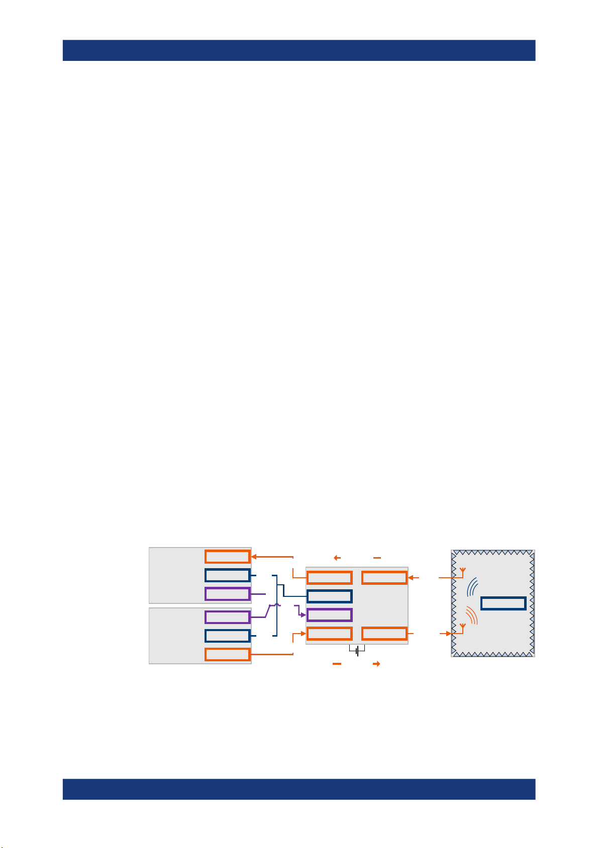
OTA microwave test setup
You can use an external frontend, e.g., for over-the-air (OTA) microwave testing. Fig-
ure 2-1 illustrates an example of a test setup including a vector signal generator, an
external frontend, a DUT inside an RF shield box and a vector signal analyzer.
The signal generator provides the IF signal and the reference signal to the external
frontend. The signal analyzer can also provide the reference signal. All instruments are
connected to the same LAN. The signal generator or signal analyzer control the external frontend via LAN using a secure sockets layer (SSL) connection, see "Frontend
control connection" on page 11
The external frontend up-converts the IF signal from the signal generator and transmits
the RF signal to the DUT (Tx mode). The DUT receives the RF signal and responds by
transmitting an RF signal to the external frontend. The frontend down-converts the RF
signal to an IF signal and transmits the IF signal to the signal analyzer (RX mode).
Vector signal
analyzer
Vector signal
generator
RF
LAN
Ref Out
Ref Out
LAN
RF
IF Out
LAN
Ref
LAN
IF In
IF Out A
LAN
Ref In
IF In B
Rx mode
R&S
FE50DTR
Tx mode
RF A
RF B
RF shield box
RF In
DUT
RF Out
Figure 2-1: Typical setup using an external frontend
10User Manual 1179.4240.02 ─ 03

R&S®SMW-K553
About the Frontend Control option
Test setup
Frontend control connection
You can control an external frontend via LAN by one control instrument, that exclusively controls the external frontend. Using an SSL connection, the control instrument
sends commands to the external frontend to perform the following actions:
●
To lock the external frontend
●
To unlock the external frontend for frontend control by another instrument
●
To set network settings of the external frontend
●
To set and read out the IF frequency, the frequency conversion factor and the frequency bands
●
To calibrate the external frontend
●
To check and update the frontend firmware
Once a lock of the SSL connection is established, the external frontend is not accessible by other instruments in the LAN. When an external frontend is locked, the LAN LED
on the front panel is orange.
Some test setups require that more than one instrument controls the external frontend
during test execution. R&S FE50DTR-type external frontend has two channels that are
an Rx and a Tx signal path. Both channels use the same internal LO and thus both
signal paths operate on the same frequency.
For details on setting up and operating external frontends, see Chapter 3, "Operating
external frontends", on page 12.
11User Manual 1179.4240.02 ─ 03

R&S®SMW-K553
3 Operating external frontends
3.1 Connecting external frontends
Operating external frontends
Connecting external frontends
This chapter provides an overview on step-by-step instructions related to connecting
and configuring external frontends.
It includes the following:
● Connecting external frontends................................................................................ 12
● Controlling external frontends................................................................................. 14
● Generating RF output signals................................................................................. 19
● Updating the firmware.............................................................................................19
This chapter provides step-by-step descriptions for connecting external frontends. Connecting procedures for relevant connector types are summarized for the R&S FE44S
as an example. Connecting to these connector types is analogous for all other external
frontends. The step-by-step descriptions cover the following topics:
●
"To connect an R&S FE44S" on page 12
●
"To connect an R&S FE50DTR" on page 14
To connect an R&S FE44S
The following procedure describes how to connect the R&S SMW to an R&S FE44S
using the "RF A" connector as IF signal output. The R&S FE44S and R&S SMW are
switched on and connected to power.
NOTICE! Cable selection. Use all cables delivered with the frontend. Other con-
1.
nections can require additional cables.
For the IF connection, use the cable IF Connecting Cable Ext. FE as delivered with
the external frontend. The cable is available under order number 1347.7552.00.
For the reference signal connection and the LAN connection, use high-quality
cables.
See "Cable selection and electromagnetic interference (EMI)" in the R&S SMW
Getting Started.
NOTICE! Risk of SMA connector damage and cable damage. Excessive tightening
2.
can damage the connecting cable, the SMA connectors and components inside the
R&S SMW.
Connect the "RF A" connector of the R&S SMW with the "IF In" connector of the
R&S FE44S.
See also section "Connecting to RF" in the R&S SMW user manual.
3. Connect the "LAN" connector with the "LAN" connector of the R&S FE44S.
See also section "Connecting to LAN" in the R&S SMW user manual.
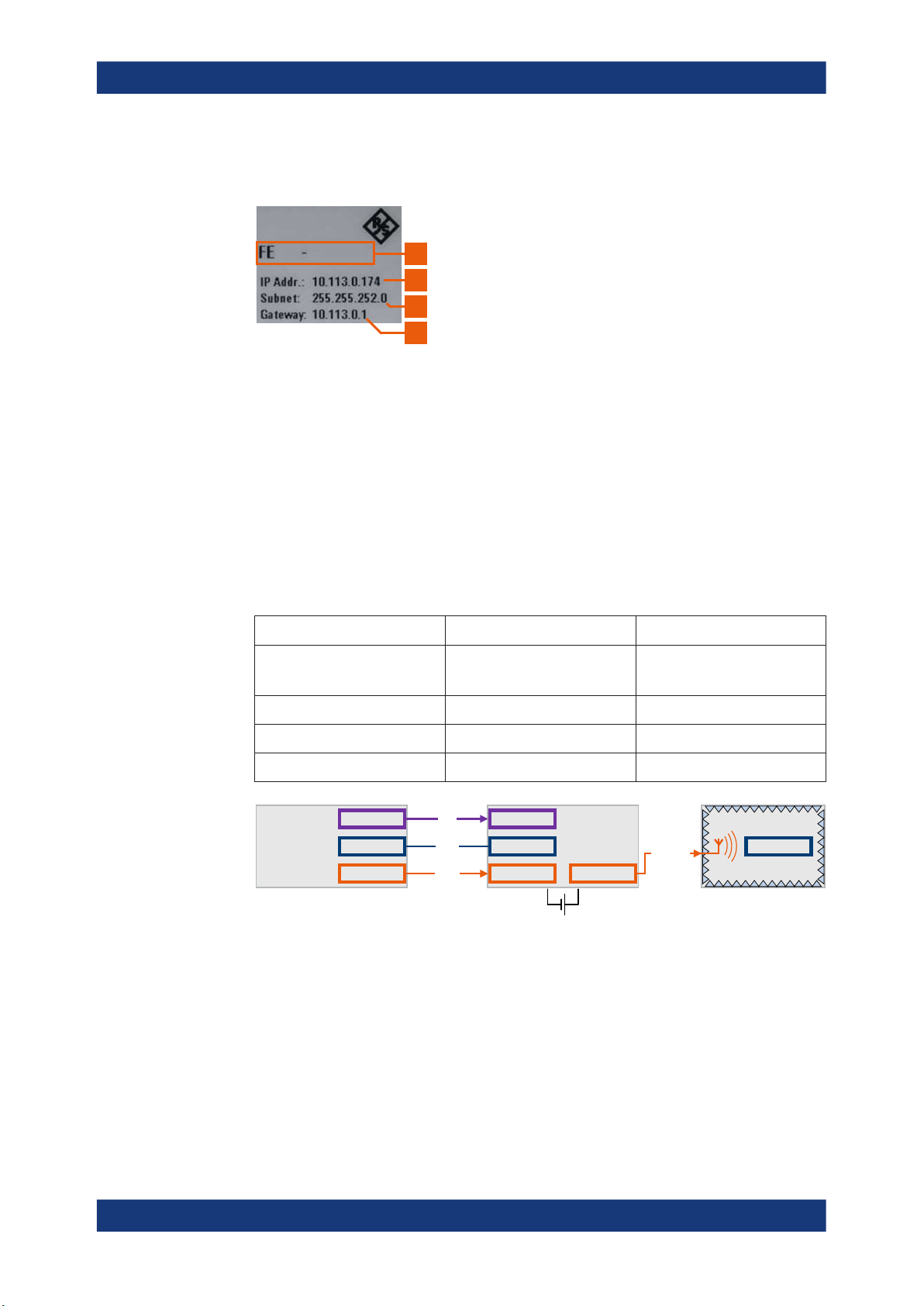
4. Check if the hostname (1), IP address (2), subnet mask (3) and gateway address
(4) of the R&S FE44S are correct.
12User Manual 1179.4240.02 ─ 03
R&S®SMW-K553
Operating external frontends
Connecting external frontends
Once connected to LAN, the electronic label on the right side panel of the
R&S FE44S displays these network parameters:
<x> <xxxxxx>
1
2
3
4
For more information, see chapter "Electronic label" in the manual of the external
frontend.
5. Connect the "REF OUT" connector of the R&S SMW with the "Ref In" connector of
the R&S FE44S.
At the R&S SMW, you have two options:
● For 10 MHz reference frequency, use the BNC connector.
● For 1 GHz reference frequency, use the SMA connector.
See also section "Connecting to Ref In/Ref Out" in the R&S SMW user manual.
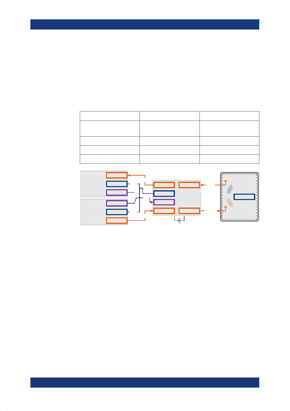
Table 3-3 and Figure 3-1 provide an overview on connections and a test setup.
Table 3-1: R&S
Signal R&S SMW R&S FE44S
Reference Connector: "REF OUT"
SMW and R&S FE44S connections
Frequency: 1 GHz, 10 MHz
"Ref In"
LAN (Control) "LAN" "LAN"
IF In "RF A"/"RF B" "IF In"
RF Out - "RF In/Out"
Ref Out
Vector signal
generator
Figure 3-1: Test setup with R&S FE44S in Tx mode: R&S SMW, R&S FE44S and RF shield box
Vector signal generator = R&S SMW
LAN
RF
Ref
LAN
IF In
Ref In
LAN
IF In RF Out
R&S
FE44S
RF Out
RF shield box
DUT
Note, that the R&S FE44S can input (Rx mode) or output (Tx mode) one RF signal at a
time. For analyzing the input RF signal from the DUT, the R&S FE44S downconverts
the signal. Also, the R&S FE44S routes the resulting IF output signal to the signal analyzer. During RF signal analysis, the R&S FE44S does not process the IF input signal
from the R&S SMW.
For a more general test setup, see "OTA microwave test setup" on page 10.
13User Manual 1179.4240.02 ─ 03
R&S®SMW-K553
Operating external frontends
Controlling external frontends
To connect an R&S FE50DTR
The R&S FE50DTR and R&S SMW are switched on and connected to power. At the
R&S FE50DTR, you connect the IF input signal from the R&S SMW, to the "IF In A" or
"IF In B" connector.
► To connect an R&S FE50DTR with the R&S SMW, follow the instructions described
in section "To connect an R&S FE44S" on page 12.
Table 3-3 and Figure 3-2 provide an overview on connections and a test setup.
Table 3-2: R&S SMW and R&S FE50DTR connections
Signal R&S SMW R&S FE50DTR
Reference Connector: "REF OUT"
Frequency: 1 GHz, 10 MHz
LAN (Control) "LAN" "LAN"
IF In "RF A" "IF In B"
RF Out - "RF Out B"
RF
R&S FSV/A
R&S SMx
Figure 3-2: Test setup: R&S SMx = R&S SMW, R&S FSV/A, R&S FE50DTR and RF shield box
LAN
Ref Out
Ref Out
LAN
RF
LAN
LAN
IF Out
Ref
IF In
IF Out A
LAN
Ref In
IF In B
RF A
R&S
FE50DTR
RF B
"Ref In"
RF shield box
RF In
RF Out
For a more general test setup, see "OTA microwave test setup" on page 10.
DUT
3.2 Controlling external frontends
This chapter provides step-by-step descriptions for controlling, updating and operating
external frontends with the R&S SMW. The descriptions cover the following topics:
●
"To configure the R&S SMW for frontend control" on page 14
●
"To configure external frontend settings" on page 16
●
"To work with R&S FE50DTR Simultaneous RX/TX connection mode" on page 17
●
"To handover frontend control to signal analyzer" on page 18
To configure the R&S SMW for frontend control
The following procedure describes how to configure the R&S SMW to establish a control connection between R&S SMW and an external frontend.
14User Manual 1179.4240.02 ─ 03

R&S®SMW-K553
Operating external frontends
Controlling external frontends
The R&S SMW is connected to the R&S FE44S, see "To connect an R&S FE44S"
on page 12. Configuration with other connected external frontends is analogous.
1. Select "Taskbar > System Config > System Configuration > External RF und I/Q".
2. Select "RF A > External Instrument > Config".
The "External Instrument Configuration" dialog opens.
3. Select the connected external frontend from "External Instrument" selection.
The selection displays available instruments in format
<product>-<serial_number>, e.g. "FE44S-123456".
4. In the field "Hostname or IP Address", check, if the hostname or IP address of the
connected external frontend is correct.
If read out correctly, hostname or IP address match with the information displayed
on the electronic label of the frontend. See step 4 of "To connect an R&S FE44S"
on page 12.
5. Select "Apply and Connect".
A message displays, if the remote connection to the external frontend is established or not.
Figure 3-3: Message displaying established remote connection
If connected successfully, you can access "Frontend Configuration" settings. See
"To configure external frontend settings" on page 16.
6. The "System Config > System Configuration > External RF und I/Q" dialog displays
the settings and state of the connected external instrument.
15User Manual 1179.4240.02 ─ 03
 Loading...