

Rohde&Schwarz R&S®SMW200A BB Power Sweep user manual User Manual

R&S®SMW-K542
Baseband Power Sweep
User Manual
(;Úð<2)
1176981202
Version 16

This document describes the following software option:
●
R&S®SMW-K542 Baseband Power Sweep (1413.9876.xx)
This manual describes firmware version FW 5.00.166.xx and later of the R&S®SMW200A.
© 2022 Rohde & Schwarz GmbH & Co. KG
Muehldorfstr. 15, 81671 Muenchen, Germany
Phone: +49 89 41 29 - 0
Email: info@rohde-schwarz.com
Internet: www.rohde-schwarz.com
Subject to change – data without tolerance limits is not binding.
R&S® is a registered trademark of Rohde & Schwarz GmbH & Co. KG.
Trade names are trademarks of the owners.
1176.9812.02 | Version 16 | R&S®SMW-K542
The following abbreviations are used throughout this manual: R&S®SMW200A is abbreviated as R&S SMW; the license types
02/03/07/11/13/16/12 are abbreviated as xx.

R&S®SMW-K542
1 Welcome to the baseband power sweep............................................. 5
1.1 Accessing the baseband power sweep dialog...........................................................5
1.2 What's new.....................................................................................................................5
1.3 Documentation overview..............................................................................................6
1.3.1 Getting started manual....................................................................................................6
1.3.2 User manuals and help................................................................................................... 6
1.3.3 Tutorials...........................................................................................................................6
1.3.4 Service manual............................................................................................................... 6
1.3.5 Instrument security procedures.......................................................................................7
1.3.6 Printed safety instructions............................................................................................... 7
1.3.7 Data sheets and brochures............................................................................................. 7
Contents
Contents
1.3.8 Release notes and open source acknowledgment (OSA).............................................. 7
1.3.9 Application notes, application cards, white papers, etc...................................................7
1.4 Scope............................................................................................................................. 8
1.5 Notes on screenshots...................................................................................................8
2 About the baseband power sweep....................................................... 9
2.1 Required options...........................................................................................................9
2.2 Correlating parameters.................................................................................................9
3 Baseband power sweep configuration and settings........................ 14
3.1 General settings.......................................................................................................... 14
3.2 Power sweep settings.................................................................................................16
3.3 Trigger settings........................................................................................................... 20
3.4 Marker settings............................................................................................................24
3.5 Clock settings..............................................................................................................26
3.6 Local and global connectors settings.......................................................................27
3.7 Sweep graphic.............................................................................................................27
4 Application example............................................................................ 30
5 Remote-control commands.................................................................32
5.1 Programming examples............................................................................................. 32
5.2 General commands.....................................................................................................37
3User Manual 1176.9812.02 ─ 16

R&S®SMW-K542
5.3 Power sweep commands........................................................................................... 39
5.4 Trigger commands......................................................................................................46
5.5 Marker commands...................................................................................................... 50
5.6 Clock commands........................................................................................................ 51
A References............................................................................................53
A.1 Baseband power sweep default values.................................................................... 53
A.2 Representation of the power sweep shapes in the settings dialog....................... 54
A.3 Representation of the power sweep graphics..........................................................58
Contents
Annex.................................................................................................... 53
List of commands................................................................................ 65
Index......................................................................................................66
4User Manual 1176.9812.02 ─ 16

R&S®SMW-K542
1 Welcome to the baseband power sweep
Welcome to the baseband power sweep
What's new
The R&S SMW-K542 is a firmware application that enables you to generate a linear
slope ramp waveform with the baseband generator.
The R&S SMW-K542 features:
●
High degree of amplitude linearity
●
Fast varying values
●
High accuracy
●
Dynamic range of 40 dB to 50 dB at the RF output.
This user manual contains a description of the functionality that the application provides, including remote control operation.
All functions not discussed in this manual are the same as in the base unit and are
described in the R&S SMW user manual. The latest version is available at:
www.rohde-schwarz.com/manual/SMW200A
Installation
You can find detailed installation instructions in the delivery of the option or in the
R&S SMW service manual.
Installation
You can find detailed installation instructions in the delivery of the option or in the
R&S SMW Service Manual.
1.1 Accessing the baseband power sweep dialog
Access:
► Select "Baseband > Misc > Power Sweep...".
A dialog box opens that displays the provided general settings.
The signal generation is not started immediately. To start signal generation with the
default settings, select "State > On".
1.2 What's new
This manual describes firmware version FW 5.00.166.xx and later of the
R&S®SMW200A.
Compared to the previous version there are editorial changes only.
5User Manual 1176.9812.02 ─ 16

R&S®SMW-K542
1.3 Documentation overview
1.3.1 Getting started manual
1.3.2 User manuals and help
Welcome to the baseband power sweep
Documentation overview
This section provides an overview of the R&S SMW user documentation. Unless specified otherwise, you find the documents on the R&S SMW product page at:
www.rohde-schwarz.com/manual/smw200a
Introduces the R&S SMW and describes how to set up and start working with the product. Includes basic operations, typical measurement examples, and general information, e.g. safety instructions, etc. A printed version is delivered with the instrument.
Separate manuals for the base unit and the software options are provided for download:
●
Base unit manual
Contains the description of all instrument modes and functions. It also provides an
introduction to remote control, a complete description of the remote control commands with programming examples, and information on maintenance, instrument
interfaces and error messages. Includes the contents of the getting started manual.
●
Software option manual
Contains the description of the specific functions of an option. Basic information on
operating the R&S SMW is not included.
The contents of the user manuals are available as help in the R&S SMW. The help
offers quick, context-sensitive access to the complete information for the base unit and
the software options.
All user manuals are also available for download or for immediate display on the Internet.
1.3.3 Tutorials
The R&S SMW provides interactive examples and demonstrations on operating the
instrument in form of tutorials. A set of tutorials is available directly on the instrument.
1.3.4 Service manual
Describes the performance test for checking compliance with rated specifications, firmware update, troubleshooting, adjustments, installing options and maintenance.
The service manual is available for registered users on the global Rohde & Schwarz
information system (GLORIS):
https://gloris.rohde-schwarz.com
6User Manual 1176.9812.02 ─ 16

R&S®SMW-K542
1.3.5 Instrument security procedures
1.3.6 Printed safety instructions
1.3.7 Data sheets and brochures
Welcome to the baseband power sweep
Documentation overview
Deals with security issues when working with the R&S SMW in secure areas. It is available for download on the Internet.
Provides safety information in many languages. The printed document is delivered with
the product.
The data sheet contains the technical specifications of the R&S SMW. It also lists the
options and their order numbers and optional accessories.
The brochure provides an overview of the instrument and deals with the specific characteristics.
See www.rohde-schwarz.com/brochure-datasheet/smw200a
1.3.8 Release notes and open source acknowledgment (OSA)
The release notes list new features, improvements and known issues of the current
firmware version, and describe the firmware installation.
The open-source acknowledgment document provides verbatim license texts of the
used open source software.
See www.rohde-schwarz.com/firmware/smw200a
1.3.9 Application notes, application cards, white papers, etc.
These documents deal with special applications or background information on particular topics.
See www.rohde-schwarz.com/application/smw200a and www.rohde-schwarz.com/
manual/smw200a
7User Manual 1176.9812.02 ─ 16

R&S®SMW-K542
1.4 Scope
Welcome to the baseband power sweep
Notes on screenshots
Tasks (in manual or remote operation) that are also performed in the base unit in the
same way are not described here.
In particular, it includes:
●
Managing settings and data lists, like saving and loading settings, creating and
accessing data lists, or accessing files in a particular directory.
●
Information on regular trigger, marker and clock signals and filter settings, if appropriate.
●
General instrument configuration, such as checking the system configuration, configuring networks and remote operation
●
Using the common status registers
For a description of such tasks, see the R&S SMW user manual.
1.5 Notes on screenshots
When describing the functions of the product, we use sample screenshots. These
screenshots are meant to illustrate as many as possible of the provided functions and
possible interdependencies between parameters. The shown values may not represent
realistic usage scenarios.
The screenshots usually show a fully equipped product, that is: with all options installed. Thus, some functions shown in the screenshots may not be available in your particular product configuration.
8User Manual 1176.9812.02 ─ 16

R&S®SMW-K542
2 About the baseband power sweep
2.1 Required options
About the baseband power sweep
Correlating parameters
The instrument generates a digital I/Q signal which varies the power values cyclically
between the start and end values. The values change according to a predefined signal
shape.
An upstream pre-sweep and RF off time allows the signal to achieve a steady state
before sweep signal generation starts, and remains steady throughout the sweep
cycle. The RF signal is adjusted once at signal start and requires no further control by
the RF level hardware control systems.
The main application fields of signals generated with baseband power sweep are
amplifier tests.
The equipment layout for processing of digital power sweep includes:
●
Option Standard or Wideband Baseband Generator (R&S SMW-B10/-B9) per signal path
●
Option Baseband main module, one/two I/Q paths to RF (R&S SMW-B13/-B13T) or
Option Wideband baseband main module two I/Q paths to RF (R&S SMW-B13XT)
●
Option Baseband Power Sweep (R&S SMW-K542) per signal path
2.2 Correlating parameters
This section describes the characteristic parameters of the baseband power sweep,
explained by means of a stair-step sweep signal. In addition, the function calculates
the constant power value of the sweep signal relative to the set RF level, and you can
display the results in the graph, see "Constant mode" on page 12.
9User Manual 1176.9812.02 ─ 16

R&S®SMW-K542
About the baseband power sweep
Correlating parameters
The characteristic parameters at a glance
5a 5b
3b
3e
2b
3c
2a 43a
1
Figure 2-1: Characteristic parameters defining the power sweep
1 = RF Blanking
2a, 2b = Pre-Sweep
3a, 3b, 3c, 3d, 3e, 3f = active power sweep
4 = Rise / Fall time
5a, 5b = additional signal characteristics
Table 2-1: Correlating parameters of the baseband power sweep
Functions Description
RF Blanking "RF Blanking Time (1)"
Lead time before pre-sweep
Pre-Sweep
Start of sweep signal generation
●
Provides settling of the signal before the actual measurement
●
the power value "Pre-Sweep (2b)" defines the starting point
●
"Pre-sweep (2b)" level, "Start Level (3a)" and the internal dwell time determine the indicated "Pre-sweep Time (2a)"
3f
3d
Power sweep
●
"Sweep Time (3a)", the time of active measurement
●
"Range (3b)"
– The sweep range the measurement is performed
– RF Blanking and Pre-Sweep are not considered
– The upper level value always corresponds to the set RF level (3d), the
corresponding lower level is derived from the upper level and the range
– With ascending slope, the "Stop Level (3d) = RF level", and the "Start
Level (3c)" is derived
Vice versa for a falling slope, the power sweep starts at the RF level, see
Example "Baseband Power Sweep with descending slope" on page 12.
– "Power Step (3e)" and "Dwell Time (3f)" define either the power step
size, or the sweep step length for "Stair Step" sweeps. One of the two
parameters can be optionally set, the other is calculated and displayed
accordingly.
10User Manual 1176.9812.02 ─ 16

R&S®SMW-K542
About the baseband power sweep
Correlating parameters
Functions Description
Fall / Rise Time
(Post-sweep time)
Sweep range Defined level value range
"Sweep Time" Defined duration of a sweep cycle
Additional signal
characteristics
"Slope" Direction (rising or falling) of the power sweep signal
"Fall Time (4)"
●
The time span the signal requires to return from the "Stop Level" to the initial
level at sweep start
●
With ascending slope, the graph shows the fall time at the end of the sweep
The "Rise Time" appears, when you generate the signal with descending
slope, see Example "Baseband Power Sweep with descending slope"
on page 12.
Indicated relevant key parameters:
●
"Resolution (5a)"
Resolution of the instrument hardware, which determines the current increment of the configured sweep signal
●
"Sample Rate (5b)"
Number of samples, resulting from the resolution
11User Manual 1176.9812.02 ─ 16

R&S®SMW-K542
About the baseband power sweep
Correlating parameters
Example: Baseband Power Sweep with descending slope
The following figure shows the example from above with the same settings, but
descending slope.
3d3c
4
Figure 2-2: Example of a stair step power sweep with descending slope
3c, 3d = changed upper and lower level (start & stop)
4 = Rise instead of Fall time (post-sweep time)
The sweep starts at the upper power value ("Start Level (3c)"), the RF level, and stops
at the low value ("Stop Level (3d)"). The "Rise Time (4)" is the time span the signal
requires to return to the start level (post-sweep time).
Constant mode
You can define an attenuation value in constant mode. Based on the RF level, the
function calculates the constant sweep power over the sweep range. The following figure shows the corresponding parameters on the example of a "Stair Step" sweep.
12User Manual 1176.9812.02 ─ 16

R&S®SMW-K542
About the baseband power sweep
Correlating parameters
3b
1
2
3a
Figure 2-3: Characteristic parameters defining the power sweep
1 = constant power attenuation
2 = constant sweep power
3a, 3b = range
Apart from the parameters mentioned under Chapter 2.2, "Correlating parameters",
on page 9, the following distinctive features apply to constant mode.
Table 2-2: Correlating parameters of constant power sweep
Functions Description
Attenuation
Constant Sweep
Power
"Attenuation (1)"
●
Adjustable constant attenuation related to the RF level
●
Both parameters determine the resulting constant sweep power "(2)"
●
Relates to the active sweep range, that means from "Start Level (3a)" to "Stop
Level (3b)"
●
RF Blanking and Pre-Sweep are not considered
"Constant sweep power (2)"
●
Derived from the RF level and the attenuation
●
Relates to the sweep range, i.e. the active measurement
●
RF Blanking and Pre-Sweep are not considered
13User Manual 1176.9812.02 ─ 16
R&S®SMW-K542
3 Baseband power sweep configuration and
Baseband power sweep configuration and settings
General settings
settings
Access:
► Select "Baseband > Misc > Power Sweep".
The remote commands required to define these settings are described in Chapter 5,
"Remote-control commands", on page 32.
Settings:
● General settings......................................................................................................14
● Power sweep settings............................................................................................. 16
● Trigger settings....................................................................................................... 20
● Marker settings........................................................................................................24
● Clock settings..........................................................................................................26
● Local and global connectors settings......................................................................27
● Sweep graphic........................................................................................................ 27
3.1 General settings
Access:
► Select "Baseband > Misc > Power Sweep".
This tab provides access to the default and the "Save/Recall" settings, as well as
the settings for configuring the I/Q power sweep of the digital baseband signal.
14User Manual 1176.9812.02 ─ 16

R&S®SMW-K542
Baseband power sweep configuration and settings
General settings
The remote commands required to define these settings are described in Chap-
ter 5.2, "General commands", on page 37.
Settings:
State..............................................................................................................................15
Set to Default................................................................................................................ 15
Save/Recall...................................................................................................................15
Generate Waveform File...............................................................................................15
State
Activates the power sweep.
Switching on this option, turns off all the other sweeps in the corresponding signal
path.
Remote command:
[:SOURce<hw>]:BB:PRAMp:STATe on page 39
Set to Default
Sets the default settings, see Chapter A.1, "Baseband power sweep default values",
on page 53.
Remote command:
[:SOURce<hw>]:BB:PRAMp:PRESet on page 37
Save/Recall
Accesses the "Save/Recall" dialog, that is the standard instrument function for saving
and recalling the complete dialog-related settings in a file. The provided navigation
possibilities in the dialog are self-explanatory.
The settings are saved in a file with predefined extension. You can define the filename
and the directory, in that you want to save the file.
See also, chapter "File and Data Management" in the R&S SMW user manual.
The power sweep settings are stored as files with the predefined file extension
*.pwr_ramp.
Remote command:
[:SOURce<hw>]:BB:PRAMp:SETTing:CATalog? on page 38
[:SOURce<hw>]:BB:PRAMp:SETTing:LOAD on page 38
[:SOURce<hw>]:BB:PRAMp:SETTing:STORe on page 38
[:SOURce<hw>]:BB:PRAMp:SETTing:DELete on page 38
Generate Waveform File
With enabled signal generation, triggers the instrument to save the current settings of
an arbitrary waveform signal in a waveform file with predefined extension *.wv. You
can define the filename and the directory, in that you want to save the file.
Using the ARB modulation source, you can play back waveform files and/or process
the file to generate multi-carrier or multi-segment signals.
Remote command:
[:SOURce<hw>]:BB:PRAMp:WAVeform:CREate on page 39
15User Manual 1176.9812.02 ─ 16

R&S®SMW-K542
3.2 Power sweep settings
Baseband power sweep configuration and settings
Power sweep settings
Access:
► Select "Baseband > Misc > Power Sweep > General".
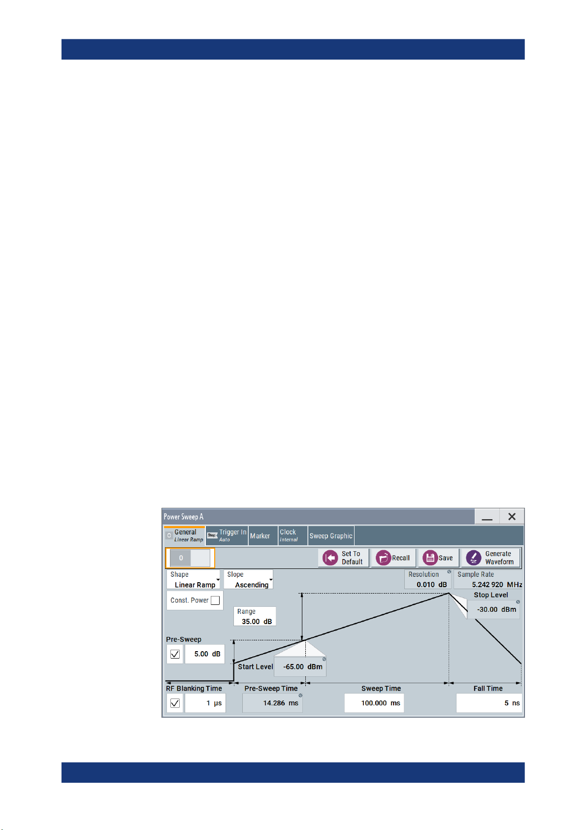
Table 3-1: Power sweep settings and the correlating constant level indication
Linear Ramp
Constant value of linear ramp
The center of the "General" tab shows the sweep signal graphically according to
the selected Shape. You can perform the settings directly in the diagram. Impacts
or interactions between the parameters are adjusted immediately (see also Chap-
ter 2.2, "Correlating parameters", on page 9). For the graphical representation of all
available power sweep shapes, see Representation of the power sweep shapes in
the settings dialog.
The remote commands required to define these settings are described in Chapter 5.3,
"Power sweep commands", on page 39.
Settings:
Shape............................................................................................................................17
Slope.............................................................................................................................17
Resolution..................................................................................................................... 17
Sample Rate................................................................................................................. 17
Const. Power.................................................................................................................18
16User Manual 1176.9812.02 ─ 16

R&S®SMW-K542
Baseband power sweep configuration and settings
Power sweep settings
└ Attenuation......................................................................................................18
└ Constant Level................................................................................................18
Range............................................................................................................................18
Start Level / Stop Level.................................................................................................18
Pre-Sweep.................................................................................................................... 18
RF Blanking Time..........................................................................................................18
Power Step....................................................................................................................19
Dwell Time.....................................................................................................................19
Sweep Time.................................................................................................................. 19
Fall Time / Rise Time / Post-Sweep Time..................................................................... 19
Shape
Selects the form of the sweep curve.
"Linear Ramp"
"Stair Step"
"Triangle"
Remote command:
[:SOURce<hw>]:BB:PRAMp:RAMP:SHAPe on page 43
The sweep sequence resembles a sawtooth.
A sweep runs from the initial level to stop level and returns to the initial level in the specified fall time.
The sweep sequence proceeds step-by-step.
A sweep runs from the initial level and switches automatically to the
next step when the Dwell Time has elapsed. When the top level is
reached the signal returns to the initial level in the specified fall time.
The sweep sequence resembles a triangle with the ascending and
descending sides of equal length.
A sweep runs from the initial level to top level and back.
Slope
Defines the direction (rising or falling) of the power sweep signal.
"Ascending"
"Descending"
Remote command:
[:SOURce<hw>]:BB:PRAMp:RAMP:SLOPe on page 44
Resolution
Displays how the instrument resolves the power step size for the currently set power
sweep.
Remote command:
[:SOURce<hw>]:BB:PRAMp:RAMP:RESolution? on page 43
Sample Rate
Displays the internally derived sample rate.
Remote command:
[:SOURce<hw>]:BB:PRAMp:RAMP:SAMPlerate? on page 43
The waveform is rising, that means, the sweep starts from the bottom
up (positive slope).
The waveform is falling. The sweep starts from the top down (negative slope).
17User Manual 1176.9812.02 ─ 16

R&S®SMW-K542
Baseband power sweep configuration and settings
Power sweep settings
Const. Power
Selects the display of constant power (see "Constant mode" on page 12.
Remote command:
[:SOURce<hw>]:BB:PRAMp:RAMP:CONStmode on page 41
Attenuation ← Const. Power
Sets a constant attenuation for the power sweep. This value refers to the RF level set
in the instrument.
Remote command:
[:SOURce<hw>]:BB:PRAMp:RAMP:ATTenuation on page 40
Constant Level ← Const. Power
Displays the constant power of the power sweep. The value is derived from the RF signal level of the instrument and the attenuation over the sweep range (see also "Con-
stant mode" on page 12).
Remote command:
[:SOURce<hw>]:BB:PRAMp:RAMP:LEVel? on page 41
Range
Determines the sweep range.
The upper and lower sweep power values are calculated relative to the signal level set
in the instrument.
Remote command:
[:SOURce<hw>]:BB:PRAMp:RAMP:RANGe on page 42
Start Level / Stop Level
Indicates the power values at the beginning and the end of the measurement.
Remote command:
[:SOURce<hw>]:BB:PRAMp:RAMP:STARtlevel? on page 45
[:SOURce<hw>]:BB:PRAMp:RAMP:STOPlevel? on page 45
Pre-Sweep
Activates the pre-sweep and displays the input filed to specify the start level value for
the pre-sweep.
The pre-sweep level value, expressed in dB, is added to the start level. Thus the signal
generation starts before the actual measurement, and the signal has therefore a certain ramp-up time to achieve a steady state, see also Sweep graphic.
The instrument indicates the internally derived ramp-up time on the time axis.
Remote command:
[:SOURce<hw>]:BB:PRAMp:RAMP:PRESweep:STATe on page 42
[:SOURce<hw>]:BB:PRAMp:RAMP:PRESweep[:LEVel] on page 42
[:SOURce<hw>]:BB:PRAMp:RAMP:PRESweep:TIME on page 42
RF Blanking Time
Activates RF output blanking, and then indicates the input field to specify the duration
for RF blanking.
18User Manual 1176.9812.02 ─ 16

R&S®SMW-K542
Baseband power sweep configuration and settings
Power sweep settings
Blanking switches off the RF signal temporarily, until the signal has settled to a steady
state, see Sweep graphic.
Using this function, you can protect a sensitive DUT as you feed a stable signal at the
start of the measurement.
Remote command:
[:SOURce<hw>]:BB:PRAMp:RAMP:BLANk[:STATe] on page 40
[:SOURce<hw>]:BB:PRAMp:RAMP:BLANk:TIME on page 40
Power Step
Activates the "Power Step" for stair step shapes, and thus the edit mode for the level
input field to specify the increment of a power step (step size).
Note: The instrument calculates either the power step, or the Dwell Time on the basis
of the sweep time and level sweep range. It depends on the parameter you want to
specify, enabled by the checkbox.
You can determine only one of the two values.
Remote command:
[:SOURce<hw>]:BB:PRAMp:RAMP:STAir:STEP[:STATe] on page 45
[:SOURce<hw>]:BB:PRAMp:RAMP:STAir:STEP:LEVel on page 45
Dwell Time
Activates the "Dwell Time" for stair step shapes, and thus the edit mode for the input
field to specify the duration of a sweep step.
Note: The instrument calculates either the dwell time, or the Power Step on the basis
of the sweep time and level sweep range. It depends on the parameter you want to
specify, enabled by the checkbox. Therefore, you can determine only one of the two
values.
Remote command:
[:SOURce<hw>]:BB:PRAMp:RAMP:STAir:DWELl[:STATe] on page 44
[:SOURce<hw>]:BB:PRAMp:RAMP:STAir:DWELl:TIME on page 44
Sweep Time
Determines the measurement duration of a sweep cycle.
Remote command:
[:SOURce<hw>]:BB:PRAMp:RAMP:SWEep:TIME on page 46
Fall Time / Rise Time / Post-Sweep Time
Specifies the time the signal needs to return from the "Stop Level" to the initial level.
The initial level is the "Pre-Sweep Level", if set, or the "Start Level".
Note: Triangle sweep signals without pre-sweep generally return to the "Start Level".
The next sweep starts when the "Pre-Sweep Time" has elapsed. The R&S SMW displays the "Pre-Sweep Time" instead of "Fall or Rise Time" (see Chapter A.2, "Repre-
sentation of the power sweep shapes in the settings dialog", on page 54).
Remote command:
[:SOURce<hw>]:BB:PRAMp:RAMP:FALL:TIME on page 41
19User Manual 1176.9812.02 ─ 16

R&S®SMW-K542
3.3 Trigger settings
Baseband power sweep configuration and settings
Trigger settings
Access:
► Select "Baseband > Misc > Power Sweep > Trigger In".
This tab provides access to the settings necessary to select and configure the trigger,
like trigger source, trigger delay, as well as to arm or trigger an internal trigger manually. The current signal generation status is displayed in the header of the tab together
with information on the enabled trigger mode. As in the "Marker" and "Clock" tabs, this
tab provides also access to the settings of the related connectors.
This section focuses on the available settings.
For information on how these settings affect the signal, refer to section "Basics on ..."
in the R&S SMW user manual.
The remote commands required to define these settings are described in Chapter 5.4,
"Trigger commands", on page 46.
Routing and enabling a trigger
The provided trigger signals are not dedicated to a particular connector. Trigger signals
can be mapped to one or more USER x or T/M connectors.
Use the Local and global connectors settings to configure the signal mapping, the
polarity, the trigger threshold and the input impedance of the input connectors.
To route and enable a trigger signal, perform the following general steps:
●
Define the signal source and the effect of a trigger event.
Select the "Trigger In > Mode" and "Trigger In > Source".
●
Define the connector where the selected signal is provided.
Use the "Global Connectors" settings.
Settings:
Trigger Settings Common to All Basebands................................................................. 21
└ Trigger Mode...................................................................................................21
└ Signal Duration Unit........................................................................................21
└ Trigger Signal Duration...................................................................................22
└ Running/Stopped............................................................................................ 22
└ Arm................................................................................................................. 22
└ Execute Trigger...............................................................................................22
└ Trigger Source................................................................................................ 22
20User Manual 1176.9812.02 ─ 16

R&S®SMW-K542
Baseband power sweep configuration and settings
Trigger settings
└ Sync. Output to External Trigger/Sync. Output to Trigger...............................23
└ External Trigger Inhibit....................................................................................24
Trigger Delay.................................................................................................................24
Trigger Settings Common to All Basebands
To enable simultaneous signal generation in all basebands, the R&S SMW couples the
trigger settings in the available basebands in any instrument's configuration involving
signal routing with signal addition. For example, in MIMO configuration, routing and
summing of basebands or of streams.
The icon
You can access and configure the common trigger source and trigger mode settings in
any of the basebands. An arm or a restart trigger event applies to all basebands, too.
You can still apply different delay to each of the triggers individually.
Trigger Mode ← Trigger Settings Common to All Basebands
Selects trigger mode, i.e. determines the effect of a trigger event on the signal generation.
For more information, refer to chapter "Basics" in the R&S SMW user manual.
●
"Auto"
The signal is generated continuously.
●
"Retrigger"
The signal is generated continuously. A trigger event (internal or external) causes a
restart.
●
"Armed Auto"
The signal is generated only when a trigger event occurs. Then the signal is generated continuously.
An "Arm" stops the signal generation. A subsequent trigger event (internal or external) causes a restart.
●
"Armed Retrigger"
The signal is generated only when a trigger event occurs. Then the signal is generated continuously. Every subsequent trigger event causes a restart.
An "Arm" stops signal generation. A subsequent trigger event (internal or external)
causes a restart.
●
"Single"
The signal is generated only when a trigger event occurs. Then the signal is generated once to the length specified at "Signal Duration".
Every subsequent trigger event (internal or external) causes a restart.
Note: Furthermore, you can specify a certain number of repetitions of the power sweep
(1 to N):
Select "Single" mode, and set the parameter "Signal Duration". The R&S SMW repeats
the sweep cycle continuously according to the set signal duration.
Remote command:
[:SOURce<hw>]:BB:PRAMp[:TRIGger]:SEQuence on page 46
indicates that common trigger settings are applied.
Signal Duration Unit ← Trigger Settings Common to All Basebands
Defines the unit for describing the length of the signal sequence to be output in the
"Single" trigger mode.
21User Manual 1176.9812.02 ─ 16
 Loading...