

Rohde&Schwarz R&S®SMR50, R&S®SMR60 Microwave Signal Generator Quick Start Guide Getting started

Quick Start Guide
Microwave Signal Generator
R&SSMR20
1104.0002.20
R&SSMR27
1104.0002.27
Printed in Germany
R&SSMR30
1104.0002.30
R&SSMR40
1104.0002.40
Test and Measurement Division
1104.3430.62-01.01- 1

Dear Customer,
R&S® is a registered trademark of Rohde & Schwarz GmbH & Co. KG.
Trade names are trademarks of the owners.

R&S SMR Contents
Contents
1 Putting into Operation .................................................................................... 1.1
General Instructions ...................................................................................................................1.1
Unpacking the Instrument ........................................................................................................1.1
Setting up the Instrument .........................................................................................................1.1
Supply Voltage.............................................................................................................................1.2
How to Ensure EMC ....................................................................................................................1.2
Power Fuses ................................................................................................................................1.2
Switching On/Off the Instrument ...............................................................................................1.2
Initial Status..............................................................................................................................1.2
RAM With Battery Back-Up.........................................................................................................1.3
Preset Setting ..............................................................................................................................1.3
Functional Test ............................................................................................................................1.3
Mounting into a 19" Rack ...........................................................................................................1.3
Explanation of Front and Rear Panel ........................................................................................1.4
Elements of the Front Panel.....................................................................................................1.4
Elements of the Rear Panel .....................................................................................................1.9
2 Short Tutorial .................................................................................................. 2.1
Sample Setting for First Users ...................................................................................................2.1
3 Manual Operation............................................................................................ 3.1
Design of the Display ..................................................................................................................3.1
Basic Operating Steps ................................................................................................................3.2
Calling the menus.....................................................................................................................3.2
Selection and Change of Parameters ......................................................................................3.3
Quick Selection of Menu (QUICK SELECT) ............................................................................3.4
Use of [FREQ] and [LEVEL] Keys............................................................................................3.5
Use of [RF ON/OFF] and [MOD ON/OFF] ...............................................................................3.5
Changing Unit of Level .............................................................................................................3.5
Correction of Input....................................................................................................................3.6
List Editor.....................................................................................................................................3.7
Select List.................................................................................................................................3.9
Delete List ................................................................................................................................3.9
Edit List...................................................................................................................................3.10
SAVE/RECALL – Storing/Calling of Instrument Settings ......................................................3.15
Menu Summary..........................................................................................................................3.16
4 Index ................................................................................................................ 4.1
1104.3430.12 3 E-3


Certificate No.: 99042
This is to certify that:
C Certificate of Conformity
E
Equipment type
Order No. Designation
SMR20 1104.0002.20 Signal Generator 1 to 20 GHz
SMR27 1104.0002.27 Signal Generator 1 to 27 GHz
SMR30 1104.0002.30 Signal Generator 1 to 30 GHz
SMR40 1104.0002.40 Signal Generator 1 to 40 GHz
SMR-B1 1104.5485.02 Option: Reference Oscillator OCXO
SMR-B5 1104.3501.02/.03 Option: AM/FM/SCAN Modulator
SMR-B11 1104.4250.02 Option: Frequency Extension
SMR-B15 1104.4989.02 Option: RF Attenuator 20 GHz
SMR-B17 1104.5233.02 Option: RF Attenuator 40 GHz
SMR-B19 1104.6281.02 Option: Rear Connector
SMR-B20 1104.6381.02 Option: Rear Connector
SMR-B23 1104.5804.02 Option: IF Input 20 GHz
complies with the provisions of the Directive of the Council of the European Union on the
approximation of the laws of the Member States
- relating to electrical equipment for use within defined voltage limits
(73/23/EEC revised by 93/68/EEC)
- relating to electromagnetic compatibility
(89/336/EEC revised by 91/263/EEC, 92/31/EEC, 93/68/EEC)
Conformity is proven by compliance with the following standards:
EN61010-1 : 1993 + A2 : 1995
EN50081-1 : 1992
EN50082-2 : 1995
Affixing the EC conformity mark as from 1999
ROHDE & SCHWARZ GmbH & Co. KG
Mühldorfstr. 15, D-81671 München
Munich, 2000-08-24 Central Quality Management FS-QZ / Becker
1104.0002.01 CE E-4


R&S SMR User Documentation
Contents of User Documentation for Microwafe
Signal Generator R&S SMR
The user documentation describes the Mikrowave-Signal Generator R&S SMR and all options. It includes a printed Quick Start Guide and a CD-ROM with the complete operating and service manual in
printable pdf-format.
The R&S SMR is equipped with a context-sensitive online help that offers a help page for each instrument function.
Quick Start Guide
The present quick start guide describes everything that is needed
to put the instrument into operation and to get familiar with the
generator. The quick start guide gives an introduction to remote
control and manual control via external monitor, mouse and keyboard.
The quick start guide is subdivided into the data sheet plus
3 chapters plus index:
The data sheet informs about specifications and characteristics
of the instrument.
Help System
Chapter 1 Describes the control elements and connectors
on the front and rear panel as well as all procedures required for putting the instrument into
operation.
Chapter 2 Gives an introduction the operating concept and
typical applications of the R&S SMA.
Chapter 3 Describes key operating modes, the structure of
the graphical interface and the principles of
manual control.
Chapter 4 Contains an index for the quick start guide.
HELP
The help system is embedded in the instrument, offering quick,
context-sensitive reference to the information needed for operation
and programming. The help contains the complete user documentation for the R&S SMR including the contents of the present quick
start guide.
1104.3430.62 0.1 E-1

User Documentation R&S SMA
Documentation CD-ROM
The CD-ROM provides the complete user documentation for the
Signal Generator:
- The complete operating manual and service manual in printable
form (*.pdf).
- The data sheet (brochure and specifications) in printable form.
Links to different useful sites in the R&S internet.
Optional Documentation
Operating Manual
The operating manual contains comprehensive information about
the instrument functions and remote control, in addition to the
chapters of the quick start guide. It includes information about
maintenance of the instrument and about error detection listing the
error messages which may be output by the instrument. It is subdivided into 10 chapters:
Chapter 1 describes the control elements and connectors on
the front and rear panel as well as all procedures
required for putting the instrument into operation.
Chapter 2 gives an introduction to the operating concept and
typical applications of the R&S SMR.
Chapter 3 describes key operating modes, the structure of the
graphical interface and the principles of manual
control.
Chapter 4 forms a reference for manual control of the
R&S SMR and contains a detailed description of all
instrument functions and their application. The
chapter also lists the remote control command corresponding to each instrument function.
Kapitel 5 describes the basics for programming the
R&S SMR, command processing and the status
reporting system.
Chapter 6 lists all the remote-control commands defined for
the instrument.
Chapter 7 contains program examples for a number of
typical applications of the R&S SMR.
Chapter 8 describes preventive maintenance and the charac-
teristics of the instrument’s interfaces.
Chapter 9 gives the status messages and a list of error mes-
sages that the R&S SMR may generate.
Chapter 10 contains an index for the operating manual.
1104.3430.62 0.2 E-1

R&S SMR User Documentation
Service Manual Instrument
The service manual - instrument informs on how to check compliance with rated specifications, on instrument function, repair, troubleshooting and fault elimination. It contains all information required for the maintenance of R&S SMR by exchanging modules.
In addition it describes how to perform a firmware update and how
to install options.
1104.3430.62 0.3 E1


R&S SMR Putting into Operation
1 Putting into Operation
his chapter contains all information about putting into operation (unpacking, connection to AC supply,
T
switching on and off), functional testing and installation of the instrument, preset settings and views of
the front and rear panel showing the controls and connectors needed for operation.
General Instructions
Before putting the SMR into operation, please make sure that
• the covers of the casing are put on and screwed,
• the ventilation openings are free,
• no signal voltage levels exceeding the permissible limits are applied at the inputs,
• the outputs of the instrument are not overloaded or connected incorrectly.
If these points are not observed, the instrument might be damaged.
Unpacking the Instrument
Take the instrument out of the shipping box and check whether the
items listed in the packing list and in the lists of accessories are all
included.
Remove the two protective caps from the front and rear of the SMR
remove protective cabs
Should the instrument be damaged, immediately notify the forwarder who shipped the instrument to you
and keep the box and packing material.
For further transport or shipment of the SMR the original packing should also be used. It is
recommended to keep at least the two protective caps for front and rear side in order to prevent
damage to the controls and connectors.
and carefully check the instrument for damage.
Setting up the Instrument
For applications in the laboratory or on a work bench, it is recommended that the support feet on the
bottom of the instrument be extended. For the LCD display, this provides the optimum viewing angle
which typically ranges from perpendicular to the display front to approximately 30° below.
Warning
The feet must be fully folded in or out. Only in this way can the stability of SML be
guaranteed and reliable operation be ensured. With the feet out, the weight of other
units put onto SML must not exceed 30 kg. The units must be secured against
slipping (eg by locking the feet of the unit at the top side of the enclosure).
When shifting the unit with the feet out, the feet might collapse and fold in. To avoid
injuries, the unit must therefore not be shifted with the feet out.
1134.9108.12 E-1 1.1

Putting into Operation R&S SMR
Supply Voltage
The SMR can be operated at a.c. systems from 100 to 120 V and 200 to 240 V at system frequencies
from 50 to 60 Hz. The power supply socket is situated at the rear of the instrument. The instrument
automatically sets itself to the voltage applied within the permissible voltage ranges. It is not necessary
to set the instrument to a certain supply voltage.
How to Ensure EMC
In order to avoid electromagnetic interference, the instrument may only be operated when it is closed
and with all shielding covers fitted. Only appropriate shielded signal and control cables may be used.
Power Fuses
The SMR is protected against short circuits by means of two fuses according to nameplate of the power
supply. The fuses are situated in the draw-out fuse holder which is inserted close to the power supply
socket (see below).
Power supply socket
Fuse holder
Power supply socket at the rear of the instrument
Switching On/Off the Instrument
O
I
On/Off switch at the front of the instrument
Initial Status
Upon switching on, the instrument automatically assumes the status which was set when it was
switched off.
If the instrument need not to be operated from the initial status any further, a defined default status
should be established by pressing the [PRESET] key prior to further settings.
Frequency accuracy after switching on when the oven-controlled reference oscillator is fitted
(option SMR-B1)
Switch on: Press switch.
The instrument is ready for operation.
Switch off: Release switch.
The reference oscillator needs some minutes of warm-up time to reach its nominal frequency. During
this period of time, the output frequency does not yet reach its final value either. In the status line in the
header field of the display the message "OVEN COLD" is displayed for this time.
1134.9108.12 E-1 1.2

R&S SMR Putting into Operation
RAM With Battery Back-Up
The SMR has a static read-write memory (CMOS-RAM) with battery back-up, in which 50 different
complete settings of the instrument can be stored (cf. Chapter 3, section "Storing and Calling of
Instrument Settings"). In addition, all data and/or lists the user enters himself, such as for list mode,
memory sequence, and user correction of the level, are stored in the RAM. Further, all data of the
calibrations running within the instrument in the SMR are stored in the RAM (cf. Chapter 4, section
"Calibration" and Service Manual Instrument). A lithium battery with a service life of approx. 5 years
serves to supply the RAM with power. When the battery is discharged, the data stored will be lost.
Exchanging the battery is described in the Service Manual Instrument.
Preset Setting
A defined setting status is achieved by pressing the [PRESET] key.
Preset Status:
RF frequency 10 GHz
RF level -20 dBm
Reference frequency internal, adjustment off
Offsets 0
Modulations switched off
Transient-free level setting switched off, level attenuator mode: Auto
Internal level control level Alc: On
User correction level Ucor: Off
LF output switched off
Sweep switched off
List mode switched off
Memory sequence switched off
Suppression of indications system security: unaltered
Protection of calibration data protection lock: unaltered
Settings stored unaltered
Data, lists etc. stored unaltered
IEC-bus address unaltered
All parameters and circuit states, even those of operating modes which are not activated, are preset by
means of Preset. The presettings going beyond the above list can be seen from the menu
representations as of Chapter 4 which each indicate the Preset setting status.
Functional Test
On switching on the instrument and permanently during operation, the SMR carries out a self test. The
ROM contents as well as the battery of the non-volatile RAM are checked. The most important
instrument functions are automatically monitored during operation. If an error is detected, the message
"Err" is displayed in the status line. For further identification of the error, press the [ERROR] key.
Thereupon a description of the error is displayed (cf. Chapter 9, section "Error Messages"). Return to
the menu exited by pressing the [BACK] key. If required, internal test points can be polled by the user
and the results be read out and displayed. Cf. Service Manual Instrument.
Mounting into a 19" Rack
Caution: Ensure free air inlet at the perforation of the side walls and air outlet at the rear of the
The SMR can be mounted into a 19" rack by means of rack adapter ZZA-94 (stock no. 396.4905.00).
The mounting instructions are attached to the adapter.
1134.9108.12 E-1 1.3
instrument in rack mounting.
Front Panel R&S SMR
PULSE
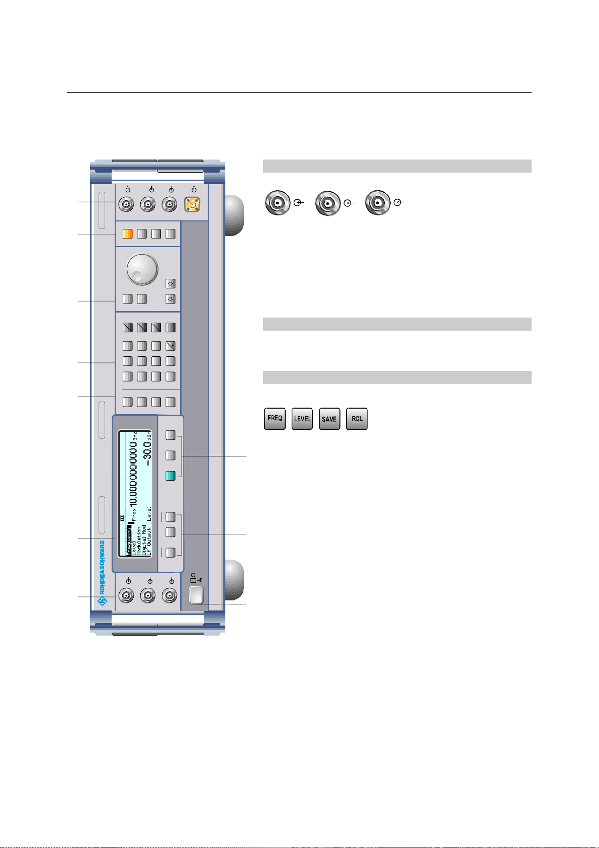
Explanation of Front and Rear Panel
Elements of the Front Panel
1
LF
PULSE/
VIDEO
RF50
EXTALC
EXT 1
EXT 2
7
MADEIN G ERMANY
1134.9008.60
RF
6
FUNCTION
MOD
ON/OFF
ON/OFF
STATUS
EXT1 Input external modulation signal alternatively for
AM, FM, ASK and FSK.
EXT2 Input external modulation signal alternatively for
AM and FM.
MENU / VARIATION
5
4
3
1 GHz ... 60 GHz
..
SIGNAL GENERATORSMR 60
BACK
SELECT HELP
AV
mV
dBAV
n
G
8 9
DATA INPUT
7
FREQ
dB(m)
A
1
m
x
k
M
ENTER
.
-
.
2 3
5 6
0
1
4
RCL
SAVE
LEVEL
ERROR
PRESET LOCAL
PULSE Input for triggering the pulse generator or for
direct control of the pulse modulation.
2 DISPLAY
Cf. Chapter 3 for the design of the display.
3
Parameter field
Parameters RF frequency and RF level can be entered
directly by means of the parameter keys, alternatively to
89
menu operation. Further, complete instrument settings can
be stored and called.
FREQ Opens the setting of the RF frequency via value
input or variation by means of a rotary knob. The
MENU2
2
MENU1
QUICK SELECT
ASSIGN
LEVEL Opens the setting of the RF level via value input
current menu is maintained. Return to the menu
by means of the [BACK] key. (Setting of the RF
frequency also in the FREQUENCY menu).
or variation by means of a rotary knob. The
EXT1
EXT2
PULSE
1
POWER
10
current menu is maintained. Return to the menu
by means of the [BACK] key. (Setting of the RF
level also in the LEVEL menu).
SAVE Opens the storing of the current instrument
setting. Memory selection is effected by entering a
number (1 to 50) and is finished by means of the
[x1/ENTER] key.
RCL Opens the calling of an instrument setting stored.
Memory selection is effected by entering a
number (1 to 50) and is finished by means of the
[x1/ENTER] key.
Cf. Chapter 3, Sections "Use of [FREQ] and
[LEVEL] Keys", "RF Frequency", "RF Level" and
"Storing and Calling of Instrument Settings".
Fig. 1-1 Front panel view
1134.9108.12 E-1 1.4

R&S SMR Front Panel
4 DATA INPUT
LF
PULSE/
VIDEO
RF50
EXTALC
Numeric input field
7
MADEIN G ERMANY
1134.9008.60
RF
6
5
FUNCTION
MENU / VARIATION
4
DATA INPUT
3
1 GHz ... 60 GHz
..
MOD
ON/OFF
ON/OFF
STATUS
BACK
SELECT HELP
AV
mV
dBAV
n
G
8 9
7
FREQ
dB(m)
A
1
m
x
k
M
ENTER
.
-
.
2 3
5 6
0
1
4
RCL
SAVE
LEVEL
Numeric values, decimal point and minus sign can be
entered by means of the digital keys.
0...9 Enters the digit.
Enters the decimal point
-/ Enters the minus sign.
Deletes the last input (digit, sign or decimal point)
- key [BACKSPACE]
Unit keys with enter function
ERROR
89
The unit keys terminate the input of values and specify the
PRESET LOCAL
SIGNAL GENERATORSMR 60
multiplication factor for the respective basic unit.
The basic units are displayed next to the input field while
numbers are entered. In the case of level settings, the unit
MENU2
2
MENU1
QUICK SELECT
ASSIGN
keys specify the unit.
G/n dBµV Selects giga/nano, with RF level dBµV.
M/µ µV Selects mega/micro, with level µV.
EXT1
EXT2
PULSE
1
POWER
k/m MV Selects kilo/milli, with level mV.
1x
10
Enter dB(m) Terminates entries in the basic unit
Selects with level dBm.
Selects with level offset and level step
In order to change to another level unit, simply press the
unit key desired. Parameter LEVEL must be activated, e.g.
by pressing the [LEVEL] key.
Cf. Chapter 3, Section "Change Unit of Level".
Fig. 1-1 Front panel view
1134.9108.12 E-1 1.5
and value inputs without unit.
width dB.
 Loading...