

Rohde&Schwarz R&S®SMM-K149 HRP UWB User Manual

R&S®SMM-K149
HRP UWB 802.15.4
User Manual
(;ÝDá2)
1179208302
Version 05

This document describes the following software options:
●
R&S®SMM-K149 HRP UWB (1441.1099.xx)
This manual describes firmware version FW 5.00.166.xx and later of the R&S®SMM100A.
© 2022 Rohde & Schwarz GmbH & Co. KG
Muehldorfstr. 15, 81671 Muenchen, Germany
Phone: +49 89 41 29 - 0
Email: info@rohde-schwarz.com
Internet: www.rohde-schwarz.com
Subject to change – data without tolerance limits is not binding.
R&S® is a registered trademark of Rohde & Schwarz GmbH & Co. KG.
Trade names are trademarks of the owners.
1179.2083.02 | Version 05 | R&S®SMM-K149
The following abbreviations are used throughout this manual: R&S®SMM100A is abbreviated as R&S SMM, R&S®WinIQSIM2 is
abbreviated as R&S WinIQSIM2; the license types 02/03/07/11/13/16/12 are abbreviated as xx.

R&S®SMM-K149
1 Welcome to the HRP UWB option........................................................ 5
1.1 Key features...................................................................................................................5
1.2 Accessing the HRP UWB dialog.................................................................................. 5
1.3 What's new.....................................................................................................................6
1.4 Documentation overview..............................................................................................6
1.4.1 Getting started manual....................................................................................................6
1.4.2 User manuals and help................................................................................................... 6
1.4.3 Service manual............................................................................................................... 7
1.4.4 Instrument security procedures.......................................................................................7
1.4.5 Printed safety instructions............................................................................................... 7
1.4.6 Data sheets and brochures............................................................................................. 7
Contents
Contents
1.4.7 Release notes and open source acknowledgment (OSA).............................................. 7
1.4.8 Application notes, application cards, white papers, etc...................................................7
1.5 Scope............................................................................................................................. 8
1.6 Notes on screenshots...................................................................................................8
2 About the HRP UWB option.................................................................. 9
2.1 Required options...........................................................................................................9
2.2 HRP UWB signal properties......................................................................................... 9
2.2.1 Frame structure...............................................................................................................9
2.2.1.1 Preamble.......................................................................................................................10
2.2.1.2 Data...............................................................................................................................11
2.3 Operating frequency bands....................................................................................... 12
3 HRP UWB configuration and settings................................................13
3.1 General settings.......................................................................................................... 13
3.2 Frame configuration settings.....................................................................................16
3.2.1 General settings............................................................................................................ 17
3.2.2 SYNC settings...............................................................................................................18
3.2.3 Data settings................................................................................................................. 20
3.2.4 MAC header configuration settings............................................................................... 24
3.2.5 STS settings..................................................................................................................28
3.3 Impairments settings.................................................................................................. 30
3User Manual 1179.2083.02 ─ 05

R&S®SMM-K149
4 Signal generation control....................................................................32
4.1 Filter/Clipping/ARB settings...................................................................................... 32
4.1.1 Filter settings.................................................................................................................32
4.1.2 Clipping settings............................................................................................................37
4.1.3 ARB settings................................................................................................................. 38
4.2 Trigger settings........................................................................................................... 38
4.3 Marker settings............................................................................................................43
4.4 Clock settings..............................................................................................................44
4.5 Local and global connectors settings.......................................................................45
5 Remote control commands.................................................................46
5.1 General commands.....................................................................................................47
5.2 Frame configuration commands............................................................................... 51
Contents
5.3 MAC header commands............................................................................................. 65
5.4 Impairments commands.............................................................................................74
5.5 Filter commands......................................................................................................... 75
5.6 Clipping commands....................................................................................................79
5.7 Trigger commands......................................................................................................80
5.8 Marker commands...................................................................................................... 86
5.9 Clock commands........................................................................................................ 88
List of commands................................................................................ 89
Index......................................................................................................92
4User Manual 1179.2083.02 ─ 05

R&S®SMM-K149
1 Welcome to the HRP UWB option
Welcome to the HRP UWB option
Accessing the HRP UWB dialog
The R&S SMM-K149 is a firmware application that adds functionality to generate signals in accordance with the HRP UWB standard. The standard is specified in
802.15.4.z specification.
This user manual contains a description of the functionality that the application provides, including remote control operation.
All functions not discussed in this manual are the same as in the base unit and are
described in the R&S SMM100A user manual. The latest version is available at:
www.rohde-schwarz.com/manual/SMM100A
Installation
You can find detailed installation instructions in the delivery of the option or in the
R&S SMM100A service manual.
● Key features..............................................................................................................5
● Accessing the HRP UWB dialog............................................................................... 5
● What's new................................................................................................................6
● Documentation overview...........................................................................................6
● Scope........................................................................................................................8
● Notes on screenshots............................................................................................... 8
1.1 Key features
The option R&S SMM-K149 HRP UWB features:
●
HRP UWB 802.15.4 signal generation compliant with HRP non-ERDEV mode
●
HRP UWB 802.15.4z signal generation compliant with HRP-ERDEV base pulse
repetition frequency (BPRF) mode
●
HRP UWB 802.15.4z signal generation compliant with HRP-ERDEV higher pulse
repetition frequency (HPRF) mode
1.2 Accessing the HRP UWB dialog
To open the dialog with HRP UWB settings
► In the block diagram of the R&S SMM100A, select "Baseband > HRP UWB".
A dialog box opens, that displays the provided general settings.
The signal generation is not started immediately. To start signal generation with the
default settings, select "State > On".
5User Manual 1179.2083.02 ─ 05

R&S®SMM-K149
1.3 What's new
1.4 Documentation overview
Welcome to the HRP UWB option
Documentation overview
This manual describes firmware version FW 5.00.166.xx and later of the
R&S®SMM100A.
Compared to the previous version, it provides the new features listed below:
●
Additional predefined SFD sequences with sequence lengths of 4 to 64 symbols,
see "SFD" on page 19.
●
Set the frame length to a fixed value of 2 ms, see "Fixed 2 ms Frame Length"
on page 16.
This section provides an overview of the R&S SMM100A user documentation. Unless
specified otherwise, you find the documents on the R&S SMM100A product page at:
www.rohde-schwarz.com/manual/smm100a
1.4.1 Getting started manual
Introduces the R&S SMM100A and describes how to set up and start working with the
product. Includes basic operations, typical measurement examples, and general information, e.g. safety instructions, etc. A printed version is delivered with the instrument.
1.4.2 User manuals and help
Separate manuals for the base unit and the software options are provided for download:
●
Base unit manual
Contains the description of all instrument modes and functions. It also provides an
introduction to remote control, a complete description of the remote control commands with programming examples, and information on maintenance, instrument
interfaces and error messages. Includes the contents of the getting started manual.
●
Software option manual
Contains the description of the specific functions of an option. Basic information on
operating the R&S SMM100A is not included.
The contents of the user manuals are available as help in the R&S SMM100A. The
help offers quick, context-sensitive access to the complete information for the base unit
and the software options.
All user manuals are also available for download or for immediate display on the Internet.
6User Manual 1179.2083.02 ─ 05

R&S®SMM-K149
1.4.3 Service manual
1.4.4 Instrument security procedures
1.4.5 Printed safety instructions
Welcome to the HRP UWB option
Documentation overview
Describes the performance test for checking compliance with rated specifications, firmware update, troubleshooting, adjustments, installing options and maintenance.
The service manual is available for registered users on the global Rohde & Schwarz
information system (GLORIS):
https://gloris.rohde-schwarz.com
Deals with security issues when working with the R&S SMM100A in secure areas. It is
available for download on the Internet.
Provides safety information in many languages. The printed document is delivered with
the product.
1.4.6 Data sheets and brochures
The data sheet contains the technical specifications of the R&S SMM100A. It also lists
the options and their order numbers and optional accessories.
The brochure provides an overview of the instrument and deals with the specific characteristics.
See www.rohde-schwarz.com/brochure-datasheet/smm100a
1.4.7 Release notes and open source acknowledgment (OSA)
The release notes list new features, improvements and known issues of the current
firmware version, and describe the firmware installation.
The open-source acknowledgment document provides verbatim license texts of the
used open source software.
See www.rohde-schwarz.com/firmware/smm100a
1.4.8 Application notes, application cards, white papers, etc.
These documents deal with special applications or background information on particular topics.
See www.rohde-schwarz.com/application/smm100a
7User Manual 1179.2083.02 ─ 05

R&S®SMM-K149
1.5 Scope
Welcome to the HRP UWB option
Notes on screenshots
Tasks (in manual or remote operation) that are also performed in the base unit in the
same way are not described here.
In particular, it includes:
●
Managing settings and data lists, like saving and loading settings, creating and
accessing data lists, or accessing files in a particular directory.
●
Information on regular trigger, marker and clock signals and filter settings, if appropriate.
●
General instrument configuration, such as checking the system configuration, configuring networks and remote operation
●
Using the common status registers
For a description of such tasks, see the R&S SMM100A user manual.
1.6 Notes on screenshots
When describing the functions of the product, we use sample screenshots. These
screenshots are meant to illustrate as many as possible of the provided functions and
possible interdependencies between parameters. The shown values may not represent
realistic usage scenarios.
The screenshots usually show a fully equipped product, that is: with all options installed. Thus, some functions shown in the screenshots may not be available in your particular product configuration.
8User Manual 1179.2083.02 ─ 05

R&S®SMM-K149
2 About the HRP UWB option
2.1 Required options
About the HRP UWB option
HRP UWB signal properties
The equipment layout for generating HRP UWB signals includes:
●
Baseband Generator (R&S SMM-B9)
●
Baseband real-time extension (R&S SMM-K520)
●
Option HRP UWB (R&S SMM-K149)
●
Option baseband extension to 240 MHz RF bandwidth (R&S SMM-K523)
●
Option baseband extension to 500 MHz RF bandwidth (R&S SMM-K524)
You can generate signals via play-back of waveform files at the signal generator. To
create the waveform file using R&S WinIQSIM2, you do not need a specific option.
To play back the waveform file at the signal generator, you have two options:
●
Install the R&S WinIQSIM2 option of the digital standard, e.g. R&S SMM-K255 for
playing LTE waveforms
●
If supported, install the real-time option of the digital standard, e.g. R&S SMM-K55
for playing LTE waveforms
For more information, see data sheet.
2.2 HRP UWB signal properties
HRP UWB PHY signals employ short, band-limited pulses sent at high rate pulse repetition frequencies (HRP).
2.2.1 Frame structure
An HRP UWB PHY frame consists of a preamble part that contains the synchronization
header (SHR) and a data part that contains a PHY header (PHR) and a PHY payload.
The SHR in the preamble comprises the synchronization (SYNC) field and a start-offrame delimiter (SFD) field.
PHY protocol data unit (PPDU)
SHR PHR PHY payload
SYNC SFD
Preamble
Figure 2-1: HRP UWB PHY frame structure
Data
9User Manual 1179.2083.02 ─ 05

R&S®SMM-K149
About the HRP UWB option
HRP UWB signal properties
HRP-ERDEV
P802.15.4z/D07 introduced optional modes and a ciphered scramble time stamp (STS)
sequence into the PHY to improve timestamp robustness and security and to increase
the accuracy of ranging measurements.
A device incorporating these modes is referred to as a higher rate pulse repetition frequency UWB PHY based enhanced ranging capable device (HRP-ERDEV) and
defined in P802.15.4z/D07, chapter 16.1, "General". Operation at the nominal 64 MHz
pulse repetition frequency (PRF) is referred to as the base pulse repetition frequency
(BPRF) mode. Operation at a higher PRF than the BPRF mode, is referred to as the
higher pulse repetition frequency (HPRF) mode.
The frame structure of HRP-ERDEV is shown in the following figure, with the STS in
different positions. The arrow shows the RMARKER reference position for each configuration, which is the peak pulse location associated with the first chip following the
SFD.
2.2.1.1
STS packet configuration zero
STS packet configuration one
STS packet configuration two
STS packet configuration three
Figure 2-2: HRP-ERDEV frame structures with RMARKER position
Preamble
SYNC SFD PHR PHY payload
SYNC SFD
SYNC
SFD
SYNC SFD
STS PHR PHY payload
PHR PHY payload STS
STS
The SYNC and SFD fields in the preamble consist of repetitions of a preamble symbol
Si. A preamble symbol is constructed from a ternary code sequence Ci = {–1,0,1} by
inserting several chip durations between code symbols. The supported code sequence
lengths are 31 and 127 as defined in IEEE Std 802.15.4-2015 chapter 16.2.4, "Preamble timing parameters". In addition, code sequence length 91 is supported as defined in
P802.15.4z/D07, chapter 16.2.5, "SYNC field". The number of inserted chip durations
is also called delta length and depends on the length of the code sequence and channel number.
The admissible values for the preamble timing parameters that result from the different
code lengths and pulse repetition frequencies are defined in IEEE Std 802.15.4-2015,
chapter 16.2.4, "Preamble timing parameters".
10User Manual 1179.2083.02 ─ 05

R&S®SMM-K149
About the HRP UWB option
HRP UWB signal properties
SYNC SFD
Si Si Si Si Si
Ci(0)
Figure 2-3: Construction of preamble symbols from a code sequence
SYNC field
The SYNC field portion of the SHR contains simple repetitions of the preamble symbol.
The number of preamble symbol repetitions are 16, 64, 1024 and 4096 as defined in
IEEE Std 802.15.4-2015, chapter 16.2.4, "Preamble timing parameters". In HPRF
mode, the HRP-ERDEV supports 32 and 64 preamble symbol repetitions as defined in
P802.15.4z/D07, chapter 16.2.5.1, "SYNC Field".
SFD field
The SFD field is spread by the preamble symbols. Each of the preamble symbols is
multiplied by a sequence of {-1, 0, 1}. The supported SFD lengths are 8 (short) and 64
(long) as defined in IEEE Std 802.15.4-2015, chapter 16.2.5.2, "SFD field". In addition,
the SFD sequences corresponding to the BPRF and HPRF modes are supported as
defined in P802.15.4z/D07, chapter 16.2.5.2, "SFD Field".
0 ... 0 Ci(1) 0 ... 0 ... Ci(K-1) 0 ... 0
Delta length
Si... 0 Si 0 -Si Si 0 0 -Si
2.2.1.2 Data
The PHR and PHY payload symbols are modulated using a combination of burst position modulation (BPM) and binary phase-shift keying (BPSK). Each symbol is composed of an active burst of UWB pulses and can carry two bits of information. One bit
is used to determine the position of a burst of pulses, while an additional bit is used to
modulate the phase (polarity) of this same burst. The various data rates are supported
by using variable-length bursts.
PHR field
The PHR field conveys the information necessary to decode the packet to the receiver,
including the following:
●
●
●
The PHR is modulated using BPM-BPSK at either 850 kb/s or 110 kb/s. For the BPRF
mode, the PHR is modulated using BPM-BPSK at 850 kb/s (or optionally at 6.8 Mb/s).
data rate used to transmit the PHY payload
length of PHY payload field
preamble duration
11User Manual 1179.2083.02 ─ 05

R&S®SMM-K149
2.3 Operating frequency bands
About the HRP UWB option
Operating frequency bands
PHY payload field
The PHY payload field is sent at the data rate indicated in the PHR. Due to the variable
code sequence lengths and the different corresponding pulse repetition frequencies
(PRFs) in the preamble, there are several admissible data rates the UWB PHY can
support. The supported data rates are defined in IEEE Std 802.15.4-2015, chapter
16.2.6, "PHR field" and P802.15.4z/D07, chapter 16.2.6.2 "PHR field for HRP-ERDEV
in BPRF mode".
The carrier center frequencies for UWB signals are defined in IEEE Std 802.15.4-2015,
chapter 16.4.1, "Operating frequency bands". The table below provides an overview of
the supported channels by R&S SMM100A.
Table 2-1: HRP UWB PHY band allocation
Band group Channel Frequency / MHz Bandwidth / MHz Mandatory/optional
0 0 499.2 499.2 Mandatory below 1 GHz
1 (low band) 1 3494.4 499.2 Optional
2 (high band) 5 6489.6 499.2 Optional
2 3993.6 499.2 Optional
3 4492.8 499.2 Mandatory in low band
4 3993.6 1331.2 Optional
6 6988.8 499.2 Optional
7 6489.6 1081.6 Optional
8 7488.0 499.2 Optional
9 7987.2 499.2 Mandatory in high band
10 8486.4 499.2 Optional
11 7987.2 1331.2 Optional
12 8985.6 499.2 Optional
13 9484.8 499.2 Optional
14 9984.0 499.2 Optional
15 9484.8 1354.97 Optional
12User Manual 1179.2083.02 ─ 05
R&S®SMM-K149
3 HRP UWB configuration and settings
3.1 General settings
HRP UWB configuration and settings
General settings
Access:
► Select "Baseband > HRP UWB 802.15.4".
The remote commands required to define these settings are described in Chapter 5,
"Remote control commands", on page 46.
Settings:
● General settings......................................................................................................13
● Frame configuration settings...................................................................................16
● Impairments settings...............................................................................................30
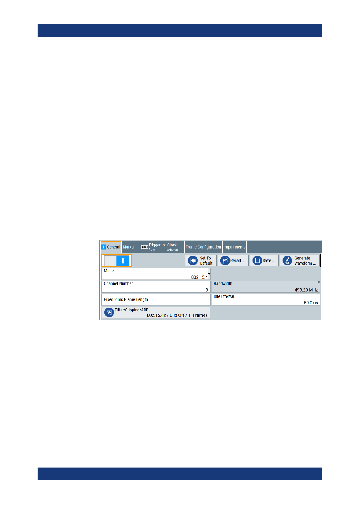
Access:
► Select "Baseband > HRP UWB 802.15.4".
The dialog provides the standard general settings, the default and the "Save/
Recall" settings. Also, it provides access to dialogs with further settings.
Settings:
State..............................................................................................................................14
Set to Default................................................................................................................ 14
Save/Recall...................................................................................................................14
Generate Waveform File...............................................................................................15
Mode............................................................................................................................. 15
Channel Number...........................................................................................................15
Bandwidth..................................................................................................................... 15
Fixed 2 ms Frame Length............................................................................................. 16
Idle Interval....................................................................................................................16
Filter/Clipping/ARB........................................................................................................16
13User Manual 1179.2083.02 ─ 05

R&S®SMM-K149
HRP UWB configuration and settings
General settings
State
Enables the HRP UWB standard.
Enabling this standard disables all the other digital standards and digital modulation
modes in the same baseband.
Remote command:
[:SOURce<hw>]:BB:HUWB:STATe on page 48
Set to Default
Calls the default settings. The values of the main parameters are listed in the following
table.
Parameter Value
"State" Not affected by the "Set to Default"
HRP UWB "Mode" "802.15.4"
"Channel Num" "0"
"Bandwidth" "499.20 MHz"
"Fixed 2 ms Frame Length" Not activated
"Idle Interval" "50.0 µs"
"Filter" "802.15.4z"
Clipping "State" "Off"
ARB "Sequence Length" "1 Frames"
"Trigger" "Auto"
"Marker" "Restart(ARB)"
"Clock" "Internal"
Remote command:
[:SOURce<hw>]:BB:HUWB:PRESet on page 48
Save/Recall
Accesses the "Save/Recall" dialog, that is the standard instrument function for saving
and recalling the complete dialog-related settings in a file. The provided navigation
possibilities in the dialog are self-explanatory.
The settings are saved in a file with predefined extension. You can define the filename
and the directory, in that you want to save the file.
See also, chapter "File and Data Management" in the R&S SMM100A user manual.
Remote command:
[:SOURce<hw>]:BB:HUWB:SETTing:CATalog on page 48
[:SOURce<hw>]:BB:HUWB:SETTing:DELete on page 49
[:SOURce<hw>]:BB:HUWB:SETTing:LOAD on page 49
[:SOURce<hw>]:BB:HUWB:SETTing:STORe on page 49
14User Manual 1179.2083.02 ─ 05

R&S®SMM-K149
HRP UWB configuration and settings
General settings
Generate Waveform File
With enabled signal generation, triggers the instrument to save the current settings of
an arbitrary waveform signal in a waveform file with predefined extension *.wv. You
can define the filename and the directory, in that you want to save the file.
Using the ARB modulation source, you can play back waveform files and/or process
the file to generate multi-carrier or multi-segment signals.
Remote command:
[:SOURce<hw>]:BB:HUWB:WAVeform:CREate on page 50
Mode
Sets the HRP UWB mode.
"802.15.4"
Enables HRP non-ERDEV mode.
"802.15.4z-BPRF"
Enables HRP-ERDEV base pulse repetition frequency (BPRF) mode.
"802.15.4z-HPRF"
Enables HRP-ERDEV higher pulse repetition frequency (HPRF)
mode.
Remote command:
[:SOURce<hw>]:BB:HUWB:STD on page 51
Channel Number
Sets the channel number, that is a 4-bit value in decimal representation.
The channel number determines the bandwidth and the code index.
Channel number Bandwidth / MHz
0, 1, 8, 12 499.2 1, 2, 9 to 16, 21 to 32
2, 5, 9, 13 499.2 3, 4, 9 to 16, 21 to 32
3, 6, 10, 14 499.2 5, 6, 9 to 16, 21 to 32
4, 11 1331.2 7, 8, 13 to 32
7 1081.6 7, 8, 13 to 32
15 1354.97 7, 8, 13 to 32
1)
Code indexes 25 to 32 require "Mode > 802.15.4z-HPRF".
Code index
1)
Remote command:
[:SOURce<hw>]:BB:HUWB:CNUMber on page 50
Bandwidth
Displays the bandwidth of the HRP UWB signal.
The bandwidth depends on the channel number, see "Channel Number" on page 15.
Remote command:
[:SOURce<hw>]:BB:HUWB:BWIDth? on page 50
15User Manual 1179.2083.02 ─ 05

R&S®SMM-K149
HRP UWB configuration and settings
Frame configuration settings
Fixed 2 ms Frame Length
Sets the frame length of a generated waveform shorter than 2 ms to a fixed value of 2
ms.
If activated, the "Idle Interval" is set to 0.0 µs by default which means the frames are
sent successively without separation.
Generated waveforms longer than 2 ms remain unaffected.
Remote command:
[:SOURce<hw>]:BB:HUWB:F2MS on page 50
Idle Interval
Sets the length of the idle interval.
Remote command:
[:SOURce<hw>]:BB:HUWB:IINTerval on page 51
Filter/Clipping/ARB
Accesses a dialog to set baseband filtering, clipping and the sequence length of the
arbitrary waveform component, see Chapter 4.1, "Filter/Clipping/ARB settings",
on page 32.
3.2 Frame configuration settings
Access:
► Select "Baseband > HRP UWB 802.15.4 > Frame Configuration".
The dialog provides settings to configure HRP UWP frames.
● General settings......................................................................................................17
● SYNC settings.........................................................................................................18
● Data settings........................................................................................................... 20
● MAC header configuration settings.........................................................................24
● STS settings............................................................................................................28
16User Manual 1179.2083.02 ─ 05

R&S®SMM-K149
3.2.1 General settings
HRP UWB configuration and settings
Frame configuration settings
Access:
► Select "Frame Configuration > General".
The tab provides settings to configure the code index and the scrambled timestamp sequence (STS) packets of HRP UWP frames.
Settings:
Code Index....................................................................................................................17
STS Packet Configuration.............................................................................................17
Code Index
Sets the code index, that determines the code sequence.
Available code indexes depend on the channel number and mode, see "Channel Num-
ber" on page 15.
Remote command:
[:SOURce<hw>]:BB:HUWB:FCONfig:CINDex on page 56
STS Packet Configuration
Requires "Mode > 802.15.4z-BPRF" or "Mode > 802.15.4z-HPRF".
Sets the scrambled timestamp sequence (STS) packet configuration. If "STS Packet
Configuration > 1/2/3", you can configure additional STS settings, see Chapter 3.2.5,
"STS settings", on page 28.
Remote command:
[:SOURce<hw>]:BB:HUWB:STS:PC on page 64
17User Manual 1179.2083.02 ─ 05

R&S®SMM-K149
3.2.2 SYNC settings
HRP UWB configuration and settings
Frame configuration settings
Access:
► Select "Frame Configuration > SYNC".
The tab provides settings to configure SYNC settings.
Settings:
Sync Length.................................................................................................................. 18
Delta Length..................................................................................................................18
SFD Length...................................................................................................................19
SFD...............................................................................................................................19
Sync Length
Sets the length of the SYNC field.
Remote command:
[:SOURce<hw>]:BB:HUWB:FCONfig:SYNLength on page 62
Delta Length
Sets the delta length. The length depends on the HRP UWB mode and bandwidth.
HRP UWB mode Bandwidth / MHz Delta length
802.15.4 499.2
1081.6
1331.2
1354.97
802.15.4z-BPRF 499.2
1081.6
1331.2
1354.97
4, 16, 64
4, 16
4, 16
4, 16
4
802.15.4z-HPRF 499.2
1081.6
1331.2
1354.97
4, 16, 64
4, 16
4, 16
4, 16
18User Manual 1179.2083.02 ─ 05

R&S®SMM-K149
HRP UWB configuration and settings
Frame configuration settings
Remote command:
[:SOURce<hw>]:BB:HUWB:FCONfig:DLENgth on page 59
SFD Length
Displays the symbol length of the start-of-frame delimiter (SFD). The length depends
on the HRP UWB mode, see Table 3-1.
Remote command:
[:SOURce<hw>]:BB:HUWB:FCONfig:SFDLength on page 61
SFD
Sets the start-of-frame delimiter (SFD) symbol sequence.
Availability of the SFD sequence and the corresponding SFD length depends on the
HRP UWB mode, see Table 3-1.
Table 3-1: SFD, SFD length and HRP UWB mode
SFD SFD length 802.15.4 802.15.4z-BPRF 802.15.4z-HPRF
0 8 - Supported Supported
1 4 - Supported Supported
2 8 - Supported Supported
3 16 - Supported Supported
4 32 - Supported Supported
User1 8 Supported Supported Supported
User2 16 Supported Supported Supported
User3 32 Supported Supported Supported
Legacy 8 Supported - -
Additional to standard-compliant SFD sequences, you can select three predefined
sequences "User1" to "User3". "802.15.4" mode also supports a legacy sequence.
Remote command:
[:SOURce<hw>]:BB:HUWB:SFD on page 62
19User Manual 1179.2083.02 ─ 05

R&S®SMM-K149
3.2.3 Data settings
HRP UWB configuration and settings
Frame configuration settings
Access:
► Select "Frame Configuration > Data".
The tab provides settings to configure physical data and physical header settings.
For "STS Packet Configuration" = 3, you cannot configure the "Data" settings.
PHY header and PHY payload coding
The data for the physical header and physical payload is segmented into code blocks
for coding via the Reed-Solomon coder. For a data length of 127 bytes (octets), there
are four code blocks segmented from four frames. Table 3-2 gives an overview.
Table 3-2: PHY data length and code block segmentation
Frame Code block b
Number Length [byte] Length [bit] Number b1 [bit] b2 [bit] b3 [bit] b4 [bit]
1 1
to
41
2 42
to
82
3 83
to
123
8
to
328
336
to
656
664
to
984
1 8
to
328
2 330 6
3 330 330 4
0 0 0
to
326
0 0
0
to
324
4 124
to
127
992
to
1016
4 330 330 330 2
to
26
20User Manual 1179.2083.02 ─ 05

R&S®SMM-K149
HRP UWB configuration and settings
Frame configuration settings
Settings:
Physical Data................................................................................................................ 21
└ Data Source....................................................................................................21
└ Viterbi Rate..................................................................................................... 22
└ Convolutional Code Constraint Length........................................................... 22
└ Hop Bursts...................................................................................................... 22
└ Chips Per Burst...............................................................................................22
└ MAC FCS........................................................................................................22
└ MAC FCS Length............................................................................................22
└ MAC Header................................................................................................... 22
└ Mean PRF.......................................................................................................23
└ Data Rate........................................................................................................23
└ PHR Data Rate Mode..................................................................................... 23
PHR (Physical Header).................................................................................................23
└ PHR Bit Rate...................................................................................................23
└ Data Length.................................................................................................... 23
└ Maximum Data Length....................................................................................24
Frame............................................................................................................................24
└ Frame Length..................................................................................................24
Physical Data
Provides settings to configure physical data.
Data Source ← Physical Data
Selects the data source.
Note: The bit order of the output data bits is least significant bit (LSB) first and most
significant bit (MSB) last.
The following standard data sources are available:
●
"All 0, All 1"
An internally generated sequence containing 0 data or 1 data.
●
"PNxx"
An internally generated pseudo-random noise sequence.
●
"Pattern"
An internally generated sequence according to a bit pattern.
Use the "Pattern" box to define the bit pattern.
●
"Data List/Select DList"
A binary data from a data list, internally or externally generated.
Select "Select DList" to access the standard "Select List" dialog.
– Select the "Select Data List > navigate to the list file *.dm_iqd > Select" to
select an existing data list.
– Use the "New" and "Edit" functions to create internally new data list or to edit
an existing one.
– Use the standard "File Manager" function to transfer external data lists to the
instrument.
See also:
●
Section "Modulation Data" in the R&S SMM100A user manual.
●
Section "File and Data Management" in the R&S SMM100A user manual.
●
Section "Data List Editor" in the R&S SMM100A user manual
21User Manual 1179.2083.02 ─ 05

R&S®SMM-K149
HRP UWB configuration and settings
Frame configuration settings
Remote command:
[:SOURce<hw>]:BB:HUWB:FCONfig:DATA on page 57
[:SOURce<hw>]:BB:HUWB:FCONfig:DATA:DSELection on page 57
[:SOURce<hw>]:BB:HUWB:FCONfig:DATA:PATTern on page 58
Viterbi Rate ← Physical Data
Displays the Viterbi rate for convolutional coding.
The rate is fixed to 0.5, except for "Chips Per Burst > 1" it is 1.0.
Remote command:
[:SOURce<hw>]:BB:HUWB:FCONfig:VRATe? on page 62
Convolutional Code Constraint Length ← Physical Data
Requires "Mode > 802.15.4z-HPRF".
Sets the constraint length of the convolutional code.
Remote command:
[:SOURce<hw>]:BB:HUWB:CCCL on page 56
Hop Bursts ← Physical Data
Requires "Mode > 802.15.4" or "Mode > 802.15.4z-BPRF".
Sets the number of hop bursts.
Remote command:
[:SOURce<hw>]:BB:HUWB:FCONfig:HOPBurst on page 59
Chips Per Burst ← Physical Data
Sets the number of chips per burst.
Remote command:
[:SOURce<hw>]:BB:HUWB:FCONfig:CPBurst on page 57
MAC FCS ← Physical Data
Activates the MAC frame check sequence (FCS) field.
Remote command:
[:SOURce<hw>]:BB:HUWB:FCONfig:MCS:STATe on page 60
MAC FCS Length ← Physical Data
Requires "MAC FCS > On".
Sets the length of the MAC frame check sequence (FCS) field.
Remote command:
[:SOURce<hw>]:BB:HUWB:FCONfig:MFL on page 60
MAC Header ← Physical Data
Accesses the "MAC Header Configuration" dialog to configure MAC header parameters.
See Chapter 3.2.4, "MAC header configuration settings", on page 24.
If the MAC header is active, the button displays the length of the MAC header and the
MAC address.
22User Manual 1179.2083.02 ─ 05

R&S®SMM-K149
HRP UWB configuration and settings
Frame configuration settings
Remote command:
[:SOURce<hw>]:BB:HUWB:MACHeader:STRing? on page 74
Mean PRF ← Physical Data
Displays the mean pulse repetition frequency (PRF). The value depends on the hop
bursts.
Remote command:
[:SOURce<hw>]:BB:HUWB:FCONfig:MPRF? on page 61
Data Rate ← Physical Data
Displays the data rate.
Remote command:
[:SOURce<hw>]:BB:HUWB:FCONfig:DR? on page 58
PHR Data Rate Mode ← Physical Data
Requires "Mode > 802.15.4z-BPRF" or "Mode > 802.15.4z-HPRF".
Sets the data rate mode of the physical header.
"DRBM_LP/DRBM_HP"
Requires "Mode > 802.15.4z-BPRF".
"DRHM_LR/DRHM_HR"
Requires "Mode > 802.15.4z-HPRF".
Remote command:
[:SOURce<hw>]:BB:HUWB:PHR:DRM on page 62
PHR (Physical Header)
Provides settings to configure the PHY header and PHY payload.
PHR Bit Rate ← PHR (Physical Header)
Displays the bit rate of the physical header. The value depends on the chips per burst.
Remote command:
[:SOURce<hw>]:BB:HUWB:FCONfig:PHRBrate? on page 61
Data Length ← PHR (Physical Header)
Sets the data length of the PHY header and PHY payload in octets.
PHY header and PHY payload data are segmented into code blocks for Reed-Solomon
encoding, see Table 3-2.
The specified maximum data length is 127 octets. For "Mode > 802.15.4z-HPRF", you
can set a maximum data length of up to 4095 octets.
Mode Maximum data length
"802.15.4z" 127 octets
"802.15.4z-BPRF" 127 octets
"802.15.4z-HPRF" 4095 octets
23User Manual 1179.2083.02 ─ 05

R&S®SMM-K149
HRP UWB configuration and settings
Frame configuration settings
Remote command:
[:SOURce<hw>]:BB:HUWB:FCONfig:DALEngth on page 58
Maximum Data Length ← PHR (Physical Header)
Requires "Mode > 802.15.4z-HPRF".
Sets the maximum data length of the physical header.
Remote command:
[:SOURce<hw>]:BB:HUWB:FCONfig:MDL on page 60
Frame
Provides information on the frame length.
Frame Length ← Frame
Displays the frame length.
The frame length is the sum of the MAC header length, the MAC frame check
sequence (FCS) field length and the data length of the physical header.
Example: Frame lengths with enabled and disabled MAC parameters
By default, the frame length is 20 octets, that is the data length of the physical header.
If you activate the MAC frame check sequence (FCS) field, the frame length increases.
Using the default "MAC FCS Length > 2 Octets", the frame length is 22 octets.
If you further activate the MAC header, the frame length increases. Using the default
"MAC Header > 11 Octets", the frame length is 33 octets.
Remote command:
n.a.
3.2.4 MAC header configuration settings
Access:
► Select "Frame Configuration > Data > MAC Header".
24User Manual 1179.2083.02 ─ 05

R&S®SMM-K149
HRP UWB configuration and settings
Frame configuration settings
The tab provides settings to configure the MAC header bits as defined in IEEE Std
802.15.4-2015.
MAC Header................................................................................................................. 25
Frame Control............................................................................................................... 25
└ Frame Type.....................................................................................................25
└ Security Enabled.............................................................................................26
└ Frame Pending............................................................................................... 26
└ AR...................................................................................................................26
└ PAN ID Compression...................................................................................... 26
└ Reserved.........................................................................................................26
└ Sequence Number Suppression.....................................................................26
└ IE Present....................................................................................................... 26
└ Destination Addressing Mode.........................................................................27
└ Frame Version.................................................................................................27
└ Source Addressing Mode................................................................................27
Sequence Number........................................................................................................ 27
Destination PAN ID........................................................................................................27
Destination Address......................................................................................................28
Source PAN ID.............................................................................................................. 28
Source Address.............................................................................................................28
MAC Header
Activates MAC header information.
Remote command:
[:SOURce<hw>]:BB:HUWB:MACHeader:STATe on page 74
Frame Control
Sets the length and the input value of the frame control field.
You can set lengths of 1 octet or 2 octets. The single bit field below ranges from least
significant bit (LSB) to most significant bit (MSB):
●
1 octet (8-bit): Set bits for fields "Frame Type" to "Reserved".
●
2 octets (16-bit): Set bits for fields "Frame Type" to "Source Addressing Mode".
Remote command:
[:SOURce<hw>]:BB:HUWB:MACHeader:LFRControl on page 70
[:SOURce<hw>]:BB:HUWB:MACHeader:CTRL on page 66
Frame Type ← Frame Control
Sets the bits in the frame type field. The value is a 3-bit value, the field is the LSB part
of the frame control field.
Table 3-3: Frame type settings (IEEE Std 802.15.4-2015, table 7.2.1.1-7)
Decimal value Binary values b2, b1, b0 Description
0 000 Beacon
1 001 Data
2 010 Acknowledgment
3 011 MAC command
25User Manual 1179.2083.02 ─ 05

R&S®SMM-K149
HRP UWB configuration and settings
Frame configuration settings
Decimal value Binary values b2, b1, b0 Description
4 100 Reserved
5 101 Multipurpose
6 110 Fragment or Frak
7 111 Extended
Remote command:
[:SOURce<hw>]:BB:HUWB:MACHeader:FTYPe on page 68
Security Enabled ← Frame Control
Sets the bit in the security enabled field.
Remote command:
[:SOURce<hw>]:BB:HUWB:MACHeader:SEENabled on page 73
Frame Pending ← Frame Control
Sets the bit in the frame pending field.
Remote command:
[:SOURce<hw>]:BB:HUWB:MACHeader:FPENding on page 68
AR ← Frame Control
Sets the bit in the AR field. It specifies if an acknowledgment is required from the recipient device on receipt of a data frame or MAC command.
Remote command:
[:SOURce<hw>]:BB:HUWB:MACHeader:AR on page 66
PAN ID Compression ← Frame Control
Sets the bit in the PAN ID compression field as defined in IEEE Std 802.15.4-2015,
table 7.2.1.5-2.
Remote command:
[:SOURce<hw>]:BB:HUWB:MACHeader:PIDComp on page 71
Reserved ← Frame Control
Sets a reserved bit for future use.
Remote command:
[:SOURce<hw>]:BB:HUWB:MACHeader:REServed on page 72
Sequence Number Suppression ← Frame Control
Requires frame control length of two octets.
Sets the bit in the sequence number suppression field.
Remote command:
[:SOURce<hw>]:BB:HUWB:MACHeader:SENSupp on page 73
IE Present ← Frame Control
Requires frame control length of two octets.
Sets the bit in the information element (IE) present field.
26User Manual 1179.2083.02 ─ 05

R&S®SMM-K149
HRP UWB configuration and settings
Frame configuration settings
The value is one, if the frame contains IEs and it is zero otherwise.
Remote command:
[:SOURce<hw>]:BB:HUWB:MACHeader:IEPResent on page 69
Destination Addressing Mode ← Frame Control
Requires frame control length of two octets.
Sets the bits in the destination addressing mode. The value is a 2-bit value.
Table 3-4: Destination/Source Addressing Mode field (IEEE Std 802.15.4-2015, Table 7-3)
Decimal value Binary values b1, b0 Description
0 00 PAN ID and address fields are not present
1 01 Reserved
2 10 Address field contains a short address (16 bit).
3 11 Address field contains an extended address (64 bit).
Remote command:
[:SOURce<hw>]:BB:HUWB:MACHeader:DADMode on page 67
Frame Version ← Frame Control
Requires frame control length of two octets.
Sets the bits in the frame version field. The value is a 2-bit value.
Remote command:
[:SOURce<hw>]:BB:HUWB:MACHeader:FVERsion on page 68
Source Addressing Mode ← Frame Control
Requires frame control length of two octets.
Sets the bits in the source addressing mode field. The value is a 2-bit value.
For valid values to enter, see "Destination Addressing Mode" on page 27.
Remote command:
[:SOURce<hw>]:BB:HUWB:MACHeader:SADMode on page 72
Sequence Number
Sets the length and the input value of the sequence number field. The value is an 8-bit
value in hexadecimal representation.
Remote command:
[:SOURce<hw>]:BB:HUWB:MACHeader:LSEQnumber on page 71
[:SOURce<hw>]:BB:HUWB:MACHeader:SEQNumber on page 73
Destination PAN ID
Sets the length and the input value of the destination PAN ID field. The value is a 16-bit
value in hexadecimal representation.
Remote command:
[:SOURce<hw>]:BB:HUWB:MACHeader:LDEPanid on page 69
[:SOURce<hw>]:BB:HUWB:MACHeader:DPANid on page 67
27User Manual 1179.2083.02 ─ 05

R&S®SMM-K149
HRP UWB configuration and settings
Frame configuration settings
Destination Address
Sets the length and the input values of the destination address field. The value is a
256-bit value in hexadecimal representation.
Remote command:
[:SOURce<hw>]:BB:HUWB:MACHeader:LDADdress on page 69
[:SOURce<hw>]:BB:HUWB:MACHeader:DADD on page 67
[:SOURce<hw>]:BB:HUWB:MACHeader:DAD2 on page 67
[:SOURce<hw>]:BB:HUWB:MACHeader:DAD3 on page 67
[:SOURce<hw>]:BB:HUWB:MACHeader:DAD4 on page 67
Source PAN ID
Sets the length and the input value of the source PAN ID field. The value is a 16-bit
value in hexadecimal representation.
Remote command:
[:SOURce<hw>]:BB:HUWB:MACHeader:LSOPanid on page 71
[:SOURce<hw>]:BB:HUWB:MACHeader:SPANid on page 73
Source Address
Sets the length and the input values of the source address field. The value is a 256-bit
value in hexadecimal representation.
Remote command:
[:SOURce<hw>]:BB:HUWB:MACHeader:LSADdress on page 70
[:SOURce<hw>]:BB:HUWB:MACHeader:SADD on page 72
[:SOURce<hw>]:BB:HUWB:MACHeader:SAD2 on page 72
[:SOURce<hw>]:BB:HUWB:MACHeader:SAD3 on page 72
[:SOURce<hw>]:BB:HUWB:MACHeader:SAD4 on page 72
3.2.5 STS settings
Access:
1. Select the HRP UWB mode:
● "General > Mode > 802.15.4z-BPRF"
● "General > Mode > 802.15.4z-HPRF"
2. Select "Frame Configuration > General > STS Packet Configuration > 1/2/3".
28User Manual 1179.2083.02 ─ 05
 Loading...