

Rohde&Schwarz R&S®SMM100A Getting Started User Manual

®
R&S
SMM100A
Vector Signal Generator
Getting Started
(;Ý=S2)
1179133502
Version 05

This document describes the R&S®SMM100A, stock no. 1440.8002.02 and its
options.
© 2022 Rohde & Schwarz GmbH & Co. KG
Muehldorfstr. 15, 81671 Muenchen, Germany
Phone: +49 89 41 29 - 0
Email: info@rohde-schwarz.com
Internet: www.rohde-schwarz.com
Subject to change – data without tolerance limits is not binding.
R&S® is a registered trademark of Rohde & Schwarz GmbH & Co. KG.
Trade names are trademarks of the owners.
1179.1335.02 | Version 05 | R&S®SMM100A
The following abbreviations are used throughout this manual: R&S®SMM100A is abbreviated as
R&S SMM100A, R&S®WinIQSIM2TM is abbreviated as R&S WinIQSIM2, R&S®VISA is abbreviated as
R&S VISA.

R&S®SMM100A
Contents
1 Safety and regulatory information....................................... 7
1.1 Safety instructions................................................................................7
1.2 Labels on R&S SMM100A...................................................................10
1.3 Warning messages in the documentation........................................10
2 Key features......................................................................... 12
3 Preparing for use................................................................. 13
3.1 Lifting and carrying............................................................................ 13
3.2 Unpacking and checking....................................................................13
Contents
3.3 Choosing the operating site.............................................................. 14
3.4 Setting up the R&S SMM100A........................................................... 14
3.4.1 Placing the R&S SMM100A on a bench top......................................... 14
3.4.2 Mounting the R&S SMM100A in a rack................................................ 16
3.5 Considerations for test setup............................................................ 17
3.6 Connecting to power.......................................................................... 18
3.7 Connecting to LAN............................................................................. 18
3.8 Connecting USB devices................................................................... 19
3.9 Connecting to RF................................................................................ 20
3.10 Connecting to LO In/Out.................................................................... 22
3.11 Connecting to Ref In/Ref Out.............................................................22
3.12 Connecting to HS Dig I/Q................................................................... 23
3.13 Switching on or off............................................................................. 24
4 Instrument tour.................................................................... 26
4.1 Front panel tour.................................................................................. 26
4.1.1 Touchscreen..........................................................................................27
3Getting Started 1179.1335.02 ─ 05

R&S®SMM100A
4.1.2 Keys...................................................................................................... 28
4.1.2.1 Utility keys.............................................................................................28
4.1.2.2 On/Standby........................................................................................... 29
4.1.2.3 Function keys........................................................................................29
4.1.2.4 Keypad..................................................................................................30
4.1.2.5 Navigation controls............................................................................... 30
Rotary knob...........................................................................................31
Navigation keys.....................................................................................31
Display keys..........................................................................................31
4.1.3 Connectors............................................................................................32
4.2 Rear panel tour....................................................................................34
Contents
4.2.1 Connectors............................................................................................36
5 Trying out the instrument................................................... 41
5.1 Generating an unmodulated carrier.................................................. 41
5.2 Generating a digitally modulated signal...........................................44
5.3 Triggering the instrument with an external signal...........................47
5.4 Enabling and configuring a marker signal....................................... 53
5.5 Verifying the generated signal with the graphics display...............54
5.6 Saving and recalling settings............................................................ 57
5.7 Generating an EUTRA/LTE signal......................................................60
6 System overview..................................................................65
6.1 Brief introduction to the instrument's concept................................65
6.2 Signal flow at a glance....................................................................... 65
6.3 Internal baseband source ("Baseband" block)................................ 67
6.4 Digital baseband input ("BB input"Block)........................................68
6.5 Additional white gaussian noise ("AWGN" block)...........................68
6.6 "I/Q stream mapper" block.................................................................68
4Getting Started 1179.1335.02 ─ 05

R&S®SMM100A
6.7 I/Q modulator ("I/Q mod" block)........................................................ 68
6.8 Analog I/Q output ("I/Q analog" block)............................................. 69
6.9 RF and analog modulations ("RF" block).........................................69
6.10 Applications examples of the R&S SMM100A..................................69
Contents
7 Instrument control............................................................... 71
7.1 Possible ways to operate the instrument......................................... 71
7.2 Means of manual interaction............................................................. 72
7.3 Understanding the display information............................................ 73
7.3.1 Status bar..............................................................................................74
7.3.2 Block diagram....................................................................................... 74
7.3.3 Taskbar................................................................................................. 76
7.3.4 Additional display characteristics.......................................................... 77
7.4 Accessing the functionality............................................................... 79
7.5 Entering data....................................................................................... 80
7.5.1 Entering numeric parameters................................................................81
7.5.2 Entering alphanumeric parameters.......................................................82
7.5.3 Undo and redo actions..........................................................................82
7.6 Getting information and help.............................................................82
7.7 Remote control....................................................................................84
7.8 Remote operation over VNC.............................................................. 85
8 Contacting customer support............................................ 86
Index..................................................................................... 87
5Getting Started 1179.1335.02 ─ 05

R&S®SMM100A
Contents
6Getting Started 1179.1335.02 ─ 05

R&S®SMM100A
Safety and regulatory information
Safety instructions
1 Safety and regulatory information
The product documentation helps you use the product safely and efficiently. Follow the instructions provided here and in the following chapters.
Intended use
The product is intended for the development, production and verification of electronic components and devices in industrial, administrative, and laboratory environments. Use the product only for its designated purpose. Observe the operating
conditions and performance limits stated in the data sheet.
Where do I find safety information?
Safety information is part of the product documentation. It warns you of potential
dangers and gives instructions on how to prevent personal injury or damage
caused by dangerous situations. Safety information is provided as follows:
●
In Chapter 1.1, "Safety instructions", on page 7. The same information is
provided in many languages as printed "Safety Instructions". The printed
"Safety Instructions" are delivered with the product.
●
Throughout the documentation, safety instructions are provided when you
need to take care during setup or operation.
1.1 Safety instructions
Products from the Rohde & Schwarz group of companies are manufactured
according to the highest technical standards. To use the products safely, follow
the instructions provided here and in the product documentation. Keep the product documentation nearby and offer it to other users.
Use the product only for its intended use and within its performance limits. Intended use and limits are described in the product documentation such as the data
sheet, manuals and the printed "Safety Instructions". If you are unsure about the
appropriate use, contact Rohde & Schwarz customer service.
Using the product requires specialists or specially trained personnel. These users
also need sound knowledge of at least one of the languages in which the user
interfaces and the product documentation are available.
7Getting Started 1179.1335.02 ─ 05

R&S®SMM100A
Never open the casing of the product. Only service personnel authorized by
Rohde & Schwarz are allowed to repair the product. If any part of the product is
damaged or broken, stop using the product. Contact Rohde & Schwarz customer
service at http://www.customersupport.rohde-schwarz.com.
Lifting and carrying the product
The product is heavy. Do not move or carry the product by yourself. A single person can only carry a maximum of 18 kg safely depending on age, gender and
physical condition. Look up the maximum weight in the data sheet. Use the product handles to move or carry the product. Do not lift by the accessories mounted
on the product. Accessories are not designed to carry the weight of the product.
To move the product safely, you can use lifting or transporting equipment such as
lift trucks and forklifts. Follow the instructions provided by the equipment manufacturer.
Safety and regulatory information
Safety instructions
Choosing the operating site
Only use the product indoors. The product casing is not waterproof. Water that
enters can electrically connect the casing with live parts, which can lead to electric shock, serious personal injury or death if you touch the casing. If
Rohde & Schwarz provides accessories designed for your product, e.g. a carrying
bag, you can use the product outdoors.
Unless otherwise specified, you can operate the product up to an altitude of
2000 m above sea level. The product is suitable for pollution degree 2 environments where nonconductive contamination can occur. For more information on
environmental conditions such as ambient temperature and humidity, see the
data sheet.
Setting up the product
Always place the product on a stable, flat and level surface with the bottom of the
product facing down. If the product is designed for different positions, secure the
product so that it cannot fall over.
If the product has foldable feet, always fold the feet completely in or out to ensure
stability. The feet can collapse if they are not folded out completely or if the product is moved without lifting it. The foldable feet are designed to carry the weight of
the product, but not an extra load.
If stacking is possible, keep in mind that a stack of products can fall over and
cause injury.
8Getting Started 1179.1335.02 ─ 05

R&S®SMM100A
If you mount products in a rack, ensure that the rack has sufficient load capacity
and stability. Observe the specifications of the rack manufacturer. Always install
the products from the bottom shelf to the top shelf so that the rack stands
securely. Secure the product so that it cannot fall off the rack.
Connecting to power
The product is an overvoltage category II product. Connect the product to a fixed
installation used to supply energy-consuming equipment such as household
appliances and similar loads. Keep in mind that electrically powered products
have risks, such as electric shock, fire, personal injury or even death.
Take the following measures for your safety:
●
Before switching on the product, ensure that the voltage and frequency indicated on the product match the available power source. If the power adapter
does not adjust automatically, set the correct value and check the rating of the
fuse.
Safety and regulatory information
Safety instructions
●
Only use the power cable delivered with the product. It complies with countryspecific safety requirements. Only insert the plug into an outlet with protective
conductor terminal.
●
Only use intact cables and route them carefully so that they cannot be damaged. Check the power cables regularly to ensure that they are undamaged.
Also ensure that nobody can trip over loose cables.
●
If the product needs an external power supply, use the power supply that is
delivered with the product or that is recommended in the product documentation or a power supply that conforms to the country-specific regulations.
●
Only connect the product to a power source with a fuse protection of maximum 20 A.
●
Ensure that you can disconnect the product from the power source at any
time. Pull the power plug to disconnect the product. The power plug must be
easily accessible. If the product is integrated into a system that does not meet
these requirements, provide an easily accessible circuit breaker at the system
level.
Cleaning the product
Use a dry, lint-free cloth to clean the product. When cleaning, keep in mind that
the casing is not waterproof. Do not use liquid cleaning agents.
9Getting Started 1179.1335.02 ─ 05

R&S®SMM100A
Safety and regulatory information
Warning messages in the documentation
Meaning of safety labels
Safety labels on the product warn against potential hazards.
Potential hazard
Read the product documentation to avoid personal injury or product damage.
Heavy product
Be careful when lifting, moving or carrying the product. Carrying the product requires
a sufficient number of persons or transport equipment.
Electrical hazard
Indicates live parts. Risk of electric shock, fire, personal injury or even death.
Hot surface
Do not touch. Risk of skin burns. Risk of fire.
Protective conductor terminal
Connect this terminal to a grounded external conductor or to protective ground. This
connection protects you against electric shock if an electric problem occurs.
1.2 Labels on R&S SMM100A
Labels on the casing inform about:
●
Personal safety, see "Connecting to power" on page 9.
●
Product and environment safety, see Table 1-1.
●
Identification of the product, see the serial number on the rear panel.
Table 1-1: Labels regarding R&S SMM100A and environment safety
Labeling in line with EN 50419 for disposal of electrical and electronic equipment after
the product has come to the end of its service life. For more information, see the product user manual, chapter "Disposal".
1.3 Warning messages in the documentation
A warning message points out a risk or danger that you need to be aware of. The
signal word indicates the severity of the safety hazard and how likely it will occur
if you do not follow the safety precautions.
10Getting Started 1179.1335.02 ─ 05

R&S®SMM100A
WARNING
Potentially hazardous situation. Could result in death or serious injury if not avoided.
CAUTION
Potentially hazardous situation. Could result in minor or moderate injury if not
avoided.
NOTICE
Potential risks of damage. Could result in damage to the supported product or to
other property.
Safety and regulatory information
Warning messages in the documentation
11Getting Started 1179.1335.02 ─ 05

R&S®SMM100A
Key features
2 Key features
The R&S SMM100A is a new high-performance signal generator developed to
meet demanding customer requirements. Offering excellent signal characteristic
and straightforward and intuitive operation, the signal generator makes signal
generation fast and easy.
Outstanding key features of the R&S SMM100A are:
●
Frequency range from 100 kHz to 44 GHz
●
Up to 1 GHz I/Q modulation bandwidth (in RF) with internal baseband
●
Support of all important digital standards such as 5G New Radio, LTE (up to
Release 15), 3GPP FDD/HSPA/HSPA+, GSM/EDGE/EDGE Evolution, WLAN
IEEE 802.11a/b/g/n, DVB-S2/DVB-S2X, LoRa
●
Excellent signal quality for high accuracy in spectral and modulation measurements
●
Intuitive operation via touchscreen with block diagram as key element
●
Graphical signal monitoring at practically every point in the signal flow
●
SCPI macro recorder and code generator for generating executable remote
control code from manual operating steps (for MATLAB®, CVI, etc.)
For more information, see data sheet.
12Getting Started 1179.1335.02 ─ 05

R&S®SMM100A
Unpacking and checking
Preparing for use
3 Preparing for use
Here, you can find basic information about setting up the product for the first time.
3.1 Lifting and carrying
► WARNING! The R&S SMM100A can be heavy, e.g., if fully equipped. Use a
lifting equipment, see also "Lifting and carrying the product" on page 8.
Use the carrying handles at the side for lifting and carrying the
R&S SMM100A.
The handles at the front are only for pushing and pulling the instrument when
mounting in a rack, see Chapter 3.4.2, "Mounting the R&S SMM100A in a
rack", on page 16.
3.2 Unpacking and checking
1. Unpack the R&S SMM100A carefully.
2. Retain the original packing material. Use it to protect the control elements and
connectors when transporting or shipping the R&S SMM100A later.
See also chapter "Transporting" in the user manual.
3. Using the delivery notes, check the equipment for completeness.
4. Check the equipment for damage.
If the delivery is incomplete or equipment is damaged, contact
Rohde & Schwarz.
13Getting Started 1179.1335.02 ─ 05

R&S®SMM100A
Setting up the R&S SMM100A
Preparing for use
3.3 Choosing the operating site
Specific operating conditions ensure proper operation and avoid damage to the
product and connected devices. For information on environmental conditions
such as ambient temperature and humidity, see the data sheet.
See also "Choosing the operating site" on page 8.
Electromagnetic compatibility classes
The electromagnetic compatibility (EMC) class indicates where you can operate
the product. The EMC class of the product is given in the data sheet.
●
Class B equipment is suitable for use in:
– Residential environments
– Environments that are directly connected to a low-voltage supply network
that supplies residential buildings
●
Class A equipment is intended for use in industrial environments. It can cause
radio disturbances in residential environments due to possible conducted and
radiated disturbances. It is therefore not suitable for class B environments.
If class A equipment causes radio disturbances, take appropriate measures to
eliminate them.
3.4 Setting up the R&S SMM100A
See also:
●
"Setting up the product" on page 8
●
"Intended use" on page 7
3.4.1 Placing the R&S SMM100A on a bench top
To place the product on a bench top
1. Place the product on a stable, flat and level surface. Ensure that the surface
can support the weight of the product. For information on the weight, see the
data sheet.
14Getting Started 1179.1335.02 ─ 05

R&S®SMM100A
Preparing for use
Setting up the R&S SMM100A
2. CAUTION! Foldable feet can collapse. See "Setting up the product"
on page 8.
Always fold the feet completely in or out. With folded-out feet, do not place
anything on top or underneath the product.
3. WARNING! A stack of products can fall over and cause injury. Never stack
more than three products on top of each other. Instead, mount them in a rack.
Stack as follows:
● If the products have foldable feet, fold them in completely.
● It is best if all products have the same dimensions (width and length). If the
products have different dimensions, stack according to size and place the
smallest product on top.
● Do not exceed the permissible total load placed on the product at the bot-
tom of the stack:
– 50 kg when stacking products of identical dimensions (left figure).
– 25 kg when stacking smaller products on top (middle figure).
Left = Stacked correctly, same dimensions
Middle = Stacked correctly, different dimensions
Right = Stacked incorrectly, too many products
4. NOTICE! Overheating can damage the product.
Prevent overheating as follows:
● Keep a minimum distance of 10 cm between the fan openings of the prod-
uct and any object in the vicinity.
● Do not place the product next to heat-generating equipment such as radia-
tors or other products.
15Getting Started 1179.1335.02 ─ 05

R&S®SMM100A
Setting up the R&S SMM100A
Preparing for use
3.4.2 Mounting the R&S SMM100A in a rack
To prepare the rack
1. Observe the requirements and instructions in "Setting up the product"
on page 8.
2. NOTICE! Insufficient airflow can cause overheating and damage the product.
Design and implement an efficient ventilation concept for the rack.
To mount the R&S SMM100A in a rack
1. Use an adapter kit that fits the dimensions of the R&S SMM100A to prepare
the instrument for rack mounting.
a) Order the rack adapter kit designed for the R&S SMM100A. For the order
number, see data sheet.
b) Mount the adapter kit. Follow the assembly instructions provided with the
adapter kit.
2. WARNING! The R&S SMM100A can be heavy, e.g., if fully equipped. Use a
lifting equipment, see also "Lifting and carrying the product" on page 8.
Lift the R&S SMM100A to shelf height.
3. Grab the handles at the front and push the R&S SMM100A onto the shelf until
the rack brackets fit closely to the rack.
4. Tighten all screws at the rack brackets with a tightening torque of 1.2 Nm to
secure the R&S SMM100A in the rack.
To unmount the R&S SMM100A from a rack
1. Loosen the screws at the rack brackets.
2. WARNING! The R&S SMM100A can be heavy, e.g., if fully equipped. Use a
lifting equipment, see also "Lifting and carrying the product" on page 8.
Bring the lifting equipment to shelf height.
3. Remove the R&S SMM100A from the rack.
4. If placing the R&S SMM100A on a bench top again, unmount the adapter kit
from the R&S SMM100A. Follow the instructions provided with the adapter kit.
16Getting Started 1179.1335.02 ─ 05

R&S®SMM100A
Considerations for test setup
Preparing for use
3.5 Considerations for test setup
Cable selection and electromagnetic interference (EMI)
Electromagnetic interference (EMI) can affect the measurement results.
To suppress electromagnetic radiation during operation:
●
Use high-quality shielded cables, especially for the following connector types:
– BNC
Double-shielded BNC cables.
How to: "To connect to non-screwable connectors (BNC)" on page 21
– SMA
Double-shielded SMA cables.
How to: "To connect to Ref In/Ref Out (reference = 1 GHz)" on page 23
– USB
Double-shielded USB cables.
How to: Chapter 3.8, "Connecting USB devices", on page 19.
See also chapter "Measuring USB cable quality" in the user manual.
– LAN
At least CAT6 STP cables.
How to: Chapter 3.7, "Connecting to LAN", on page 18
●
Always terminate open cable ends.
●
Ensure that connected external devices comply with EMC regulations.
●
Use cables of the same type and equal length for connection to the I/Q and
I/Q Bar interfaces of the instrument.
●
Use the cable R&S SMU-Z6 for connection to the Dig I/Q interfaces of the
instrument. The cable is available under order number 1415.0201.02.
●
Use the cable R&S DIGIQ-HS for connection to the HS Dig I/Q interfaces of
the instrument. The cable is available under order number 3641.2948.03.
How to: Chapter 3.12, "Connecting to HS Dig I/Q", on page 23
Signal input and output levels
Information on signal levels is provided in the data sheet. Keep the signal levels
within the specified ranges to avoid damage to the R&S SMM100A and connected devices.
17Getting Started 1179.1335.02 ─ 05

R&S®SMM100A
Preventing electrostatic discharge (ESD)
Electrostatic discharge is most likely to occur when you connect or disconnect a
DUT.
► NOTICE! Electrostatic discharge can damage the electronic components of
the product and the device under test (DUT).
Ground yourself to prevent electrostatic discharge damage:
a) Use a wrist strap and cord to connect yourself to ground.
b) Use a conductive floor mat and heel strap combination.
Preparing for use
Connecting to LAN
3.6 Connecting to power
For safety information, see "Connecting to power" on page 9.
1. Plug the AC power cable into the AC power connector on the rear panel of the
instrument. Only use the AC power cable delivered with the R&S SMM100A.
2. Plug the AC power cable into a power outlet with ground contact.
The required ratings are listed next to the AC power connector and in the data
sheet.
3.7 Connecting to LAN
Network environment
Before connecting the product to a local area network (LAN), consider the following:
●
Install the latest firmware to reduce security risks.
●
For internet or remote access, use secured connections if applicable.
●
Ensure that the network settings comply with the security policies of your company. Contact your local system administrator or IT department before connecting your product to your company LAN.
●
When connected to the LAN, the product may potentially be accessed from
the internet, which may be a security risk. For example, attackers might misuse or damage the product.
18Getting Started 1179.1335.02 ─ 05
R&S®SMM100A
Connecting USB devices
To connect to LAN
The connector is located on the rear panel .
► Connect the LAN socket via an RJ-45 cable to the LAN.
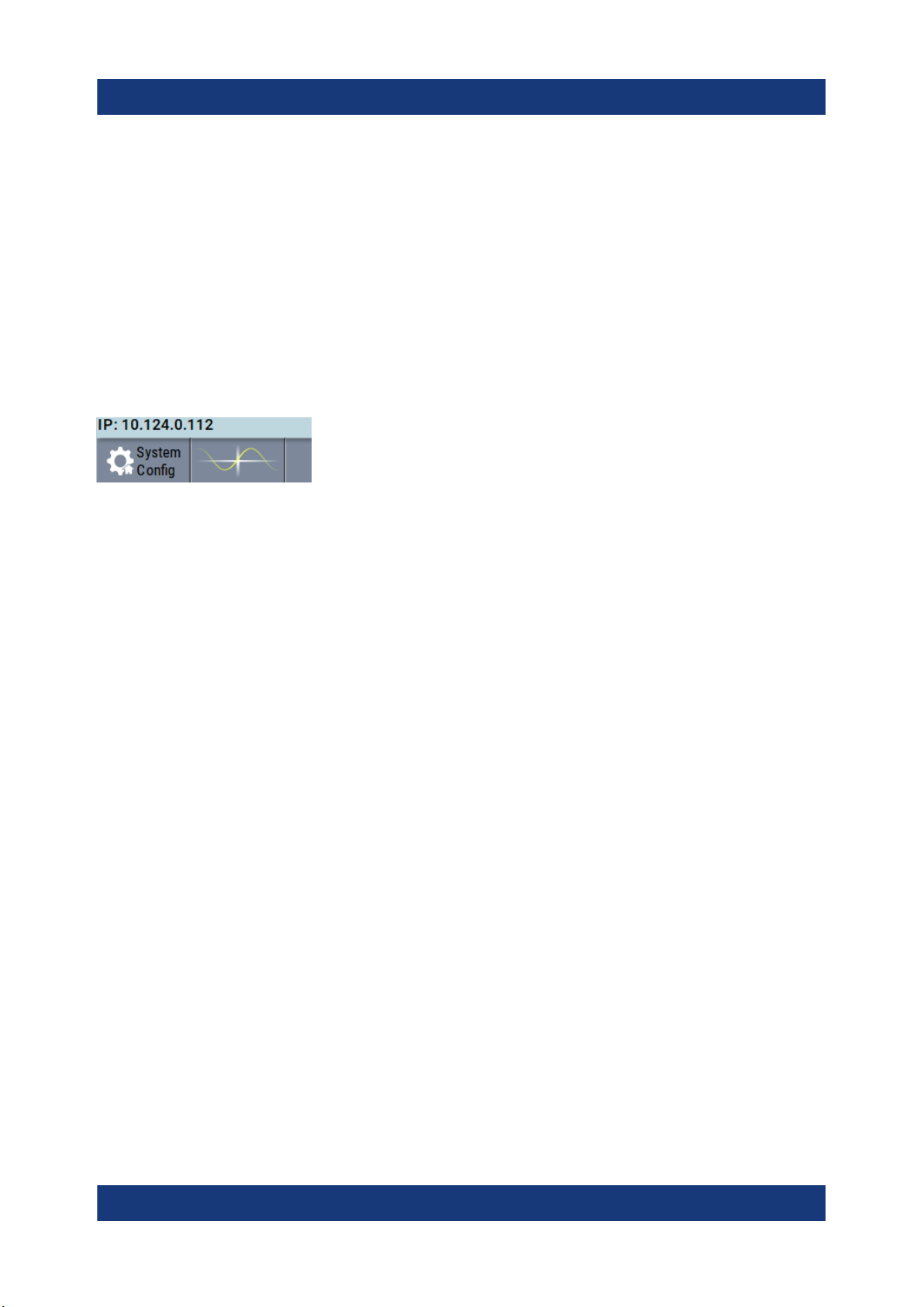
By default, the R&S SMM100A is configured to use DHCP (dynamic host configuration protocol) and no static IP address is configured.
If switched on and connected to the LAN, the R&S SMM100A displays the
address information on the screen.
Figure 3-1: IP address indication on the screen (example)
Preparing for use
See also the chapter "Connecting the Instrument to the Network (LAN)" in the
user manual.
3.8 Connecting USB devices
You can connect or disconnect all USB devices from the R&S SMM100A during
operation.
To connect USB storage devices
USB storage devices, such as memory sticks, allow data transfer from or to the
R&S SMM100A. You can also use them for firmware updates.
► Connect the USB storage device to any of the USB connectors.
To connect USB devices with external power supply
1. NOTICE! Connected devices with external power supply can feed back current into the 5 V power supply of the USB interface and thus damage the
R&S SMM100A.
Ensure that there is no connection between the positive pole of the power
supply and the +5 V power pin of the USB interface (VBUS).
2. Connect the USB storage device to any of the USB connectors.
19Getting Started 1179.1335.02 ─ 05

R&S®SMM100A
To connect a keyboard
► Connect the keyboard to any of the USB connectors.
When connected, the R&S SMM100A detects the keyboard automatically. A
detected keyboard has the default layout English – US.
To connect a mouse
► Connect the mouse to any of the USB connectors.
When connected, the R&S SMM100A detects the mouse automatically.
To connect power sensors
You can connect power sensors of the R&S NRP families to any of the USB connectors.
Preparing for use
Connecting to RF
See chapter "Using Power Sensors" in the user manual.
3.9 Connecting to RF
The connector is located on the front panel.
If you have the instrument equipped with an option for rear panel connectors, the
RF output connector is on the rear panel.
To prepare for connecting to RF
1. NOTICE! Damaged or not clean connections can lead to RF insertion loss
and mismatch, and even premature wear of the connectors.
Before connecting to the port, inspect the RF connector visually to check that
it is clean, undamaged and mechanically compatible.
See the application note 1MA99 for information on how to handle and maintain the RF port, to minimize measurement deviations and ensure its longevity.
2. NOTICE! Risk of instrument damage. Excessive reverse power or DC voltage
at the RF connector can damage the instrument.
Make sure that signal power and DC limits as given in the data sheet.
3. If the R&S SMM100A is switched on, deactivate the RF output, before connecting an RF cable to the RF connector.
20Getting Started 1179.1335.02 ─ 05

R&S®SMM100A
In the block diagram, select the block "RF" > "RF Level" > "RF ON > Off".
4. Use a high-quality RF cable that matches the RF connector type.
See "Cable selection and electromagnetic interference (EMI)" on page 17.
To connect to non-screwable connectors (BNC)
► To connect the RF cable with the RF connector, proceed as follows:
a) Carefully align the connector of the cable and the RF connector along a
common axis.
b) Mate the connectors along the common axis until the male pin of the con-
nector of the cable engages with the female socket of the RF connector.
To connect to screwable connectors
1. Use a high-quality cable that matches the connector type.
See "Cable selection and electromagnetic interference (EMI)" on page 17.
Preparing for use
Connecting to RF
2. NOTICE! Risk of instrument damage and connector damage. Excessive tightening can damage the cables and the connectors. However, if you do not
tighten the connectors enough, the measurement results can be inaccurate.
To connect the cable with the connector, proceed as follows:
a) Carefully align the connector of the cable and the connector along a com-
mon axis.
b) Mate the connectors along the common axis until the male pin of the inner
connector engages with the female socket of the outer connector.
c) Turn the nut of the outer connector until the connectors are firmly coupled.
d) Torque the nut to the specified limit using a calibrated torque wrench. Hold
the opposite connector part stationary with a spanner.
For torque limits of the most relevant connector types, see Table 3-1.
For more information, see chapter "Handling" of the application note 1MA99.
If your instrument is equipped with a test port adapter, see the application note
1MA100.
The connector types listed in this table represent the common connectors provided by Rohde & Schwarz. It is considered as general information and therefore
can contain connector types that do not apply to your instrument.
See "RF" on page 32.
21Getting Started 1179.1335.02 ─ 05
R&S®SMM100A
Connecting to Ref In/Ref Out
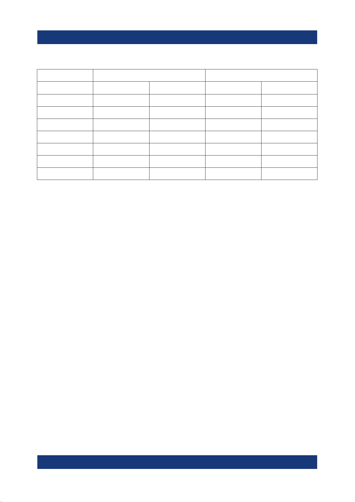
Table 3-1: Connector types and torque limits
Type Torque limit Nut opening
Preparing for use
N 13.3 1.5 3/4 20
SMA 5 0.56 5/16 8
3.5 mm 8 0.9 5/16 8
2.92 mm 8 0.9 5/16 8
2.4 mm 8 0.9 5/16 8
1.85 mm 8 0.9 5/16 8
1.0 mm 3 0.34 0.236 6
lb-Inch Nm Inch mm
To prevent RF output switch-off
► NOTICE! If you set a too high output level without a load connected to the
instrument, the reverse power can exceed a limit forcing the R&S SMM100A
to switch off the RF output.
Connect a load with sufficient return loss as given in the data sheet.
3.10 Connecting to LO In/Out
"LO In/Out" connectors are Subminiature Version A (SMA) connectors.
The connector is located on the rear panel .
Follow the instructions in "To connect to screwable connectors" on page 21.
See also chapter "Local Oscillator Coupling" in the user manual.
3.11 Connecting to Ref In/Ref Out
The connector is located on the rear panel .
22Getting Started 1179.1335.02 ─ 05

R&S®SMM100A
Preparing for use
Connecting to HS Dig I/Q
To connect to Ref In/Ref Out (reference < 1 GHz)
For connection, the R&S SMM100A provides BNC connectors.
► Follow the instructions in "To connect to non-screwable connectors (BNC)"
on page 21.
To connect to Ref In/Ref Out (reference = 1 GHz)
For connection, the R&S SMM100A provides SMA connectors.
► Follow the instructions in "To connect to screwable connectors" on page 21.
3.12 Connecting to HS Dig I/Q
The HS Dig I/Q connector comprises a QSFP+ (Quad Small Form-factor Pluggable) socket, that has two components: a QSFP+ cage and a QSFP+ connector.
The QSFP+ cable is equipped with the QSFP+ plug.
3
1
2
1 = QSFP+ plug
2 = QSFP+ cage
3 = QSFP+ connector
The connector is located on the rear panel .
To connect to HS Dig I/Q interface
1. For connection, use the QSFP+ cable R&S DIGIQ-HS.
See "Cable selection and electromagnetic interference (EMI)" on page 17.
2. Hold the QSFP+ plug of the cable by its panes.
23Getting Started 1179.1335.02 ─ 05
R&S®SMM100A
Preparing for use
Switching on or off
3. Turn the QSFP+ cable, so that the release tab shows upwards.
4. Insert and push the QSFP+ plug into the QSFP+ cage.
To disconnect from HS Dig I/Q interface
1. NOTICE! If you pull the cable, you can damage the cable and the HS Dig I/Q
connector.
Pull the release tab.
2. Pull the QSFP+ plug out of the QSFP+ cage.
See also "Digital Baseband Input Settings" in the user manual.
3.13 Switching on or off
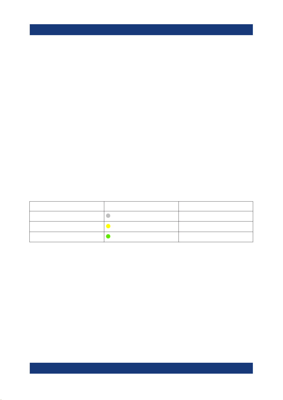
The following table provides an overview of power states, LEDs and power switch
positions.
Table 3-2: Overview of power states
State LED Position of power switch
Off
Standby
Ready
gray
orange
green
[0]
[I]
[I]
To switch on the R&S SMM100A
The R&S SMM100A is off but connected to power. See Chapter 3.6, "Connecting
to power", on page 18.
1. Set the switch on the power supply to position [I].
The switch is located on the rear panel.
The LED of the [On/Standby] key is orange.
2. Wait until the oven-controlled oscillator (OCXO) warms up. For the warm-up
time, see data sheet.
3. Press the [On/Standby] key.
Key and LED are located on the front panel.
24Getting Started 1179.1335.02 ─ 05

R&S®SMM100A
The LED changes to green. The R&S SMM100A boots.
When starting for the first time, the R&S SMM100A starts with the default settings. When restarting the instrument, the settings depend on the instrument
configuration before shut-down.
See the chapter "Saving and Recalling Instrument Settings" in the user manual.
When the instrument is switched on, it automatically monitors main functions. You
can query erroneous functions. In addition to automatic monitoring, you can perform maintenance tasks.
See:
●
Chapter "Querying Error Messages" in the user manual.
●
Chapter "Performing Maintenance Tasks" in the user manual.
Preparing for use
Switching on or off
To shut down the product
The product is in the ready state.
► Press the [On/Standby] key.
The operating system shuts down. The LED changes to orange.
In the standby state, the power switch circuits and the OCXO are active. To deactivate them, disconnect the instrument from the power supply.
To disconnect from power
The R&S SMM100A is in the standby state.
1. NOTICE! Risk of data loss. If you disconnect the product from power when it
is in the ready state, you can lose settings and data. Shut it down first.
Set the toggle switch on the power supply to position [0].
The LED of the [On/Standby] key is switched off.
2. Disconnect the R&S SMM100A from the power source.
25Getting Started 1179.1335.02 ─ 05
R&S®SMM100A
Instrument tour
Front panel tour
4 Instrument tour
This chapter explains the control elements and the connectors of the
R&S SMM100A. The views of the front panel and the rear panel help you to get
familiar with the instrument and to perform first steps. For specifications of the
interfaces, see the data sheet.
The meanings of the labels on the R&S SMM100A are described in Chapter 1.2,
"Labels on R&S SMM100A", on page 10.
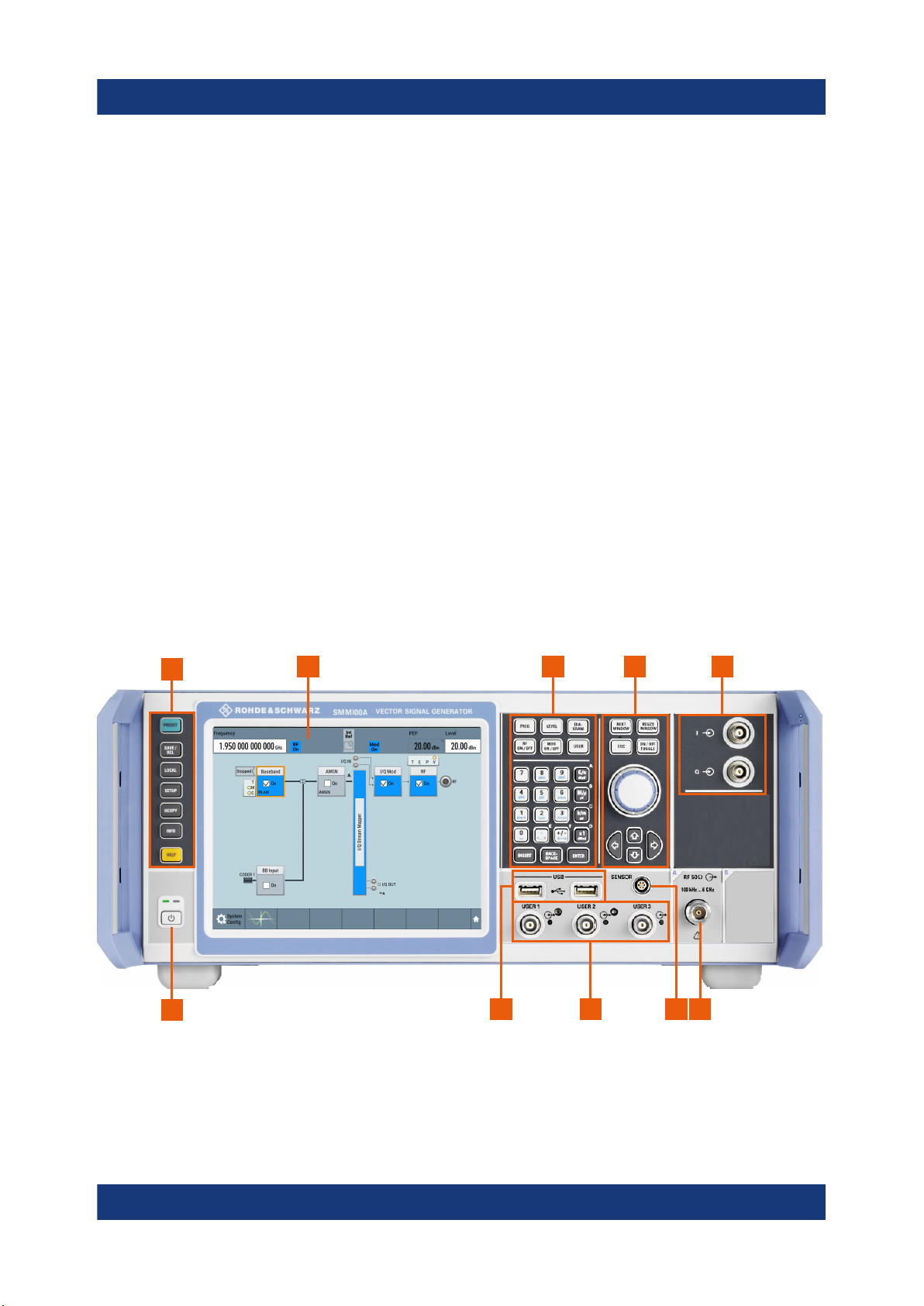
4.1 Front panel tour
This section provides an overview of the control elements and connectors on the
front panel of the R&S SMM100A. On the rear panel, you find all further connectors of the unit, see Chapter 4.2, "Rear panel tour", on page 34. The user interface can be displayed on a remote PC station used to manually remote control
the instrument.
1
10
Figure 4-1: Front panel view
1 = Utility keys, page 28
2 = Touchscreen, page 27
3 = Keypad, page 30 and Function keys, page 29
4 = Navigation controls, page 30
2 3 4 5
89
67
26Getting Started 1179.1335.02 ─ 05

R&S®SMM100A
Instrument tour
Front panel tour
5 = I/Q, page 32
6 = RF, page 32
7 = Sensor, page 33
8 = User x, page 33
9 = USB, page 33
10 = On/Standby, page 29
4.1.1 Touchscreen
The block diagram and the most important settings are displayed on the screen
on the front panel. Also, the screen display provides status and setting information and allows you to quickly reconfigure the signal flow. The screen is touchsensitive, offering an alternative means of user interaction for quick and easy
handling of the instrument.
1
2
Figure 4-2: Touchscreen elements
1 = Status bar (frequency and level display)
2 = Block diagram
3 = Taskbar/softkey bar
3
27Getting Started 1179.1335.02 ─ 05
 Loading...