

Rohde&Schwarz R&S®SMCVB-K165 ISDB-T/TSB User Manual

R&S®SMCVB-K165
ISDB-T/TSB
User Manual
(;Ý:62)
1179100602
Version 04

This document describes the following software options:
●
R&S®SMCVB-K165 ISDB-T/TSB (1434.3919.xx)
This manual describes firmware version FW 5.00.122.xx and later of the R&S®SMCV100B.
© 2022 Rohde & Schwarz GmbH & Co. KG
Muehldorfstr. 15, 81671 Muenchen, Germany
Phone: +49 89 41 29 - 0
Email: info@rohde-schwarz.com
Internet: www.rohde-schwarz.com
Subject to change – data without tolerance limits is not binding.
R&S® is a registered trademark of Rohde & Schwarz GmbH & Co. KG.
Trade names are trademarks of the owners.
1179.1006.02 | Version 04 | R&S®SMCVB-K165
The following abbreviations are used throughout this manual: R&S®SMCV100B is abbreviated as R&S SMCVB, R&S®WinIQSIM2 is
abbreviated as R&S WinIQSIM2

R&S®SMCVB-K165
Contents
1 Welcome to the ISDB-T/TSB option..................................................... 7
1.1 Accessing the ISDB-T/TSB dialog............................................................................... 7
1.2 What's new.....................................................................................................................7
1.3 Documentation overview..............................................................................................7
1.3.1 Getting started manual....................................................................................................8
1.3.2 User manuals and help................................................................................................... 8
1.3.3 Service manual............................................................................................................... 8
1.3.4 Instrument security procedures.......................................................................................8
1.3.5 Printed safety instructions............................................................................................... 8
1.3.6 Data sheets and brochures............................................................................................. 9
1.3.7 Release notes and open source acknowledgment (OSA).............................................. 9
Contents
1.3.8 Application notes, application cards, white papers, etc...................................................9
1.4 Scope............................................................................................................................. 9
1.5 Notes on screenshots.................................................................................................10
2 About the ISDB-T/TSB option............................................................. 11
2.1 Required options.........................................................................................................11
3 ISDB-T configuration and settings..................................................... 12
3.1 General settings.......................................................................................................... 12
3.2 Input signal settings................................................................................................... 14
3.2.1 General settings............................................................................................................ 15
3.2.2 Info................................................................................................................................ 18
3.2.3 Test signal settings........................................................................................................20
3.2.4 IP channel x settings..................................................................................................... 22
3.3 Coding settings........................................................................................................... 25
3.3.1 General settings............................................................................................................ 26
3.3.2 System settings.............................................................................................................29
3.4 EEW settings............................................................................................................... 31
3.4.1 General settings............................................................................................................ 32
3.4.2 EC 1/2 settings..............................................................................................................34
3.5 Special settings...........................................................................................................36
3.6 Global connector settings..........................................................................................38
3User Manual 1179.1006.02 ─ 04

R&S®SMCVB-K165
3.7 TS player...................................................................................................................... 38
3.7.1 TS Player settings......................................................................................................... 40
3.7.2 Player output settings....................................................................................................43
3.7.3 Seamless loop settings................................................................................................. 46
3.8 Local IP data network settings.................................................................................. 48
4 Performing ISDB-T/TSB signal generation tasks..............................51
4.1 Configuring the input signal...................................................................................... 51
4.1.1 How to apply an external IP input signal....................................................................... 51
4.1.2 How to apply an external TS input signal......................................................................54
4.1.3 How to generate an internal TS signal.......................................................................... 55
4.2 Monitoring the input signal........................................................................................ 56
4.2.1 How to monitor external IP input data........................................................................... 56
Contents
4.2.2 How to monitor an external TS input signal.................................................................. 57
4.2.3 How to monitor an internal TS player signal................................................................. 57
5 Remote-control commands.................................................................58
5.1 General commands.....................................................................................................59
5.2 Input commands......................................................................................................... 60
5.2.1 General commands.......................................................................................................61
5.2.2 Info commands..............................................................................................................63
5.2.3 Test signal commands...................................................................................................65
5.2.4 IP subsystem.................................................................................................................67
5.3 Coding commands......................................................................................................70
5.3.1 General commands.......................................................................................................70
5.3.2 System commands........................................................................................................73
5.4 EEW commands.......................................................................................................... 75
5.5 Special commands......................................................................................................79
5.6 TSGen subsystem.......................................................................................................82
5.7 BCIP subsystem..........................................................................................................90
Glossary: Abbreviations......................................................................93
4User Manual 1179.1006.02 ─ 04

R&S®SMCVB-K165
Glossary: Specifications..................................................................... 95
List of commands................................................................................ 96
Index......................................................................................................99
Contents
5User Manual 1179.1006.02 ─ 04

R&S®SMCVB-K165
Contents
6User Manual 1179.1006.02 ─ 04

R&S®SMCVB-K165
1 Welcome to the ISDB-T/TSB option
The R&S SMCVB-K165 is a firmware application that adds functionality to generate
signals in accordance with the ISDB-T/ISDB-TSB digital standard.
The R&S SMCVB-K165 option features:
●
This user manual contains a description of the functionality that the application provides, including remote control operation.
All functions not discussed in this manual are the same as in the base unit and are
described in the R&S SMCV100B user manual. The latest version is available at:
www.rohde-schwarz.com/manual/SMCV100B
Installation
You can find detailed installation instructions in the delivery of the option or in the
R&S SMCV100B service manual.
Welcome to the ISDB-T/TSB option
Documentation overview
ISDB-T/ISDB-TSB signal generation
1.1 Accessing the ISDB-T/TSB dialog
To open the dialog with ISDB-T/TSB settings
► In the block diagram of the R&S SMCV100B, select "Baseband > ISDB-T/TSB".
A dialog box opens that displays the provided general settings.
The signal generation is not started immediately. To start signal generation with the
default settings, select "State > On".
1.2 What's new
This manual describes firmware version FW 5.00.122.xx and later of the
R&S®SMCV100B.
Compared to the previous version there are editorial changes only.
1.3 Documentation overview
This section provides an overview of the R&S SMCV100B user documentation. Unless
specified otherwise, you find the documents on the R&S SMCV100B product page at:
www.rohde-schwarz.com/manual/smcv100b
7User Manual 1179.1006.02 ─ 04

R&S®SMCVB-K165
1.3.1 Getting started manual
Introduces the R&S SMCV100B and describes how to set up and start working with the
product. Includes basic operations, typical measurement examples, and general information, e.g. safety instructions, etc. A printed version is delivered with the instrument.
1.3.2 User manuals and help
Separate manuals for the base unit and the software options are provided for download:
●
●
Welcome to the ISDB-T/TSB option
Documentation overview
Base unit manual
Contains the description of all instrument modes and functions. It also provides an
introduction to remote control, a complete description of the remote control commands with programming examples, and information on maintenance, instrument
interfaces and error messages. Includes the contents of the getting started manual.
Software option manual
Contains the description of the specific functions of an option. Basic information on
operating the R&S SMCV100B is not included.
The contents of the user manuals are available as help in the R&S SMCV100B. The
help offers quick, context-sensitive access to the complete information for the base unit
and the software options.
All user manuals are also available for download or for immediate display on the Internet.
1.3.3 Service manual
Describes the performance test for checking compliance with rated specifications, firmware update, troubleshooting, adjustments, installing options and maintenance.
The service manual is available for registered users on the global Rohde & Schwarz
information system (GLORIS):
https://gloris.rohde-schwarz.com
1.3.4 Instrument security procedures
Deals with security issues when working with the R&S SMCV100B in secure areas. It
is available for download on the Internet.
1.3.5 Printed safety instructions
Provides safety information in many languages. The printed document is delivered with
the product.
8User Manual 1179.1006.02 ─ 04

R&S®SMCVB-K165
1.3.6 Data sheets and brochures
The data sheet contains the technical specifications of the R&S SMCV100B. It also
lists the options and their order numbers and optional accessories.
The brochure provides an overview of the instrument and deals with the specific characteristics.
See www.rohde-schwarz.com/brochure-datasheet/smcv100b
1.3.7 Release notes and open source acknowledgment (OSA)
The release notes list new features, improvements and known issues of the current
firmware version, and describe the firmware installation.
The open-source acknowledgment document provides verbatim license texts of the
used open source software.
See www.rohde-schwarz.com/firmware/smcv100b
Welcome to the ISDB-T/TSB option
Scope
1.3.8 Application notes, application cards, white papers, etc.
These documents deal with special applications or background information on particular topics.
See www.rohde-schwarz.com/application/smcv100b
1.4 Scope
Tasks (in manual or remote operation) that are also performed in the base unit in the
same way are not described here.
In particular, it includes:
●
Managing settings and data lists, like saving and loading settings, creating and
accessing data lists, or accessing files in a particular directory.
●
Information on regular trigger, marker and clock signals and filter settings, if appropriate.
●
General instrument configuration, such as checking the system configuration, configuring networks and remote operation
●
Using the common status registers
For a description of such tasks, see the R&S SMCV100B user manual.
9User Manual 1179.1006.02 ─ 04

R&S®SMCVB-K165
1.5 Notes on screenshots
When describing the functions of the product, we use sample screenshots. These
screenshots are meant to illustrate as many as possible of the provided functions and
possible interdependencies between parameters. The shown values may not represent
realistic usage scenarios.
The screenshots usually show a fully equipped product, that is: with all options installed. Thus, some functions shown in the screenshots may not be available in your particular product configuration.
Welcome to the ISDB-T/TSB option
Notes on screenshots
10User Manual 1179.1006.02 ─ 04

R&S®SMCVB-K165
2 About the ISDB-T/TSB option
In the 1990s, the Japanese Association of Radio Industries and Business (ARIB)
developed a transmission standard for digital terrestrial broadcasting. Unlike the transmission standards already in use in the other parts of the world, the television, radio
and data services are to be covered by one standard. The Japanese broadcasting
standard ISDB-T (Terrestrial Integrated Services Digital Broadcasting) was established,
in which these services can be transmitted separately in many combinations.
Comprehensive test trials proved the system performance. The characteristics of the
transmission system were verified in these field trials. The following capabilities should
be particularly mentioned: single frequency network (SFN), the positive characteristics
in mobile reception and narrowband reception where only a part of the transmitted data
is evaluated (partial reception).
Layer-specific parameters are appended with (A|B|C).
About the ISDB-T/TSB option
Required options
2.1 Required options
The equipment layout for generating ISDB-T/TSB signals includes:
●
Base unit
●
Option Enable Broadcast Standard (R&S SMCVB-K519)
●
Option ISDB-T/TSB (R&S SMCVB-K165)
11User Manual 1179.1006.02 ─ 04
R&S®SMCVB-K165
3 ISDB-T configuration and settings
Access:
► Select "Baseband > ISDB-T".
The remote commands required to define these settings are described in Chapter 5,
"Remote-control commands", on page 58.
Settings:
● General settings......................................................................................................12
● Input signal settings................................................................................................ 14
● Coding settings....................................................................................................... 25
● EEW settings...........................................................................................................31
● Special settings.......................................................................................................36
● Global connector settings........................................................................................38
● TS player.................................................................................................................38
● Local IP data network settings................................................................................ 48
ISDB-T configuration and settings
General settings
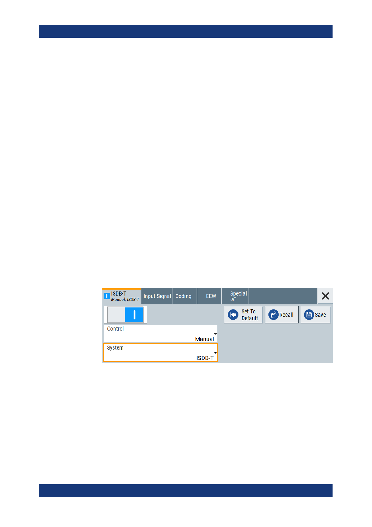
3.1 General settings
Access:
► Select "Baseband > ISDB-T".
This tab provides functionality for calling default settings, save and recall settings
and ISDB-T system settings.
Settings:
State..............................................................................................................................13
Set To Default................................................................................................................13
Save/Recall...................................................................................................................13
Control...........................................................................................................................13
System.......................................................................................................................... 13
12User Manual 1179.1006.02 ─ 04

R&S®SMCVB-K165
State
Activates the standard and deactivates all the other digital standards and digital modulation modes in the same path.
Remote command:
[:SOURce<hw>]:BB:ISDBt:STATe on page 59
Set To Default
Calls the default settings. The values of the main parameters are listed in the following
table.
Remote command:
[:SOURce<hw>]:BB:ISDBt:PRESet on page 59
Save/Recall
Accesses the "Save/Recall" dialog, that is the standard instrument function for saving
and recalling the complete dialog-related settings in a file. The provided navigation
possibilities in the dialog are self-explanatory.
The settings are saved in a file with predefined extension. You can define the filename
and the directory, in that you want to save the file.
See also, chapter "File and Data Management" in the R&S SMCV100B user manual.
ISDB-T configuration and settings
General settings
Parameter Value
State Not affected by the "Set to Default"
Remote command:
[:SOURce<hw>]:BB:ISDBt:SETTing:CATalog on page 59
[:SOURce<hw>]:BB:ISDBt:SETTing:DELete on page 60
[:SOURce<hw>]:BB:ISDBt:SETTing:LOAD on page 60
[:SOURce<hw>]:BB:ISDBt:SETTing:STORe on page 60
Control
Defines the configuration mode of the coder.
"Auto"
"Manual"
The coder is configured by the transport stream.
The coder is configured manually.
Remote command:
[:SOURce<hw>]:BB:ISDBt:CONTrol on page 71
System
Sets the ISDB-T system.
ISDB-TSB (see ISDB-TSB) utilizes the same structure of OFDM segments as ISDB-T.
However, the number of segments is different.
"ISDB-T"
13 segments. You can set the number of hierarchical layers.
See " Segments (A|B|C)" on page 30.
"ISDB-TSB (1 SEG)"
1 segment and 1 hierarchical layer.
13User Manual 1179.1006.02 ─ 04

R&S®SMCVB-K165
"ISDB-TSB (3 SEG)"
Remote command:
[:SOURce<hw>]:BB:ISDBt:SYSTem on page 72
3.2 Input signal settings
Access:
► Select "Baseband > ISDB-T/TSB > Input Signal".
Input signal tasks
The settings allow you to perform the following tasks:
●
●
●
ISDB-T configuration and settings
Input signal settings
3 segments and 2 hierarchical layers.
The dialog provides access to settings to configure the input signal.
Selecting an MPEG TS source
Displaying information about the selected MPEG TS (e.g. data rate)
Configuring the internal MPEG TS test packets or internal IP test packets
How to: Chapter 4.1, "Configuring the input signal", on page 51.
Common input signal settings
The setting of the following parameters is used for all broadcast standards.
●
"Source"
●
"Input/Input Type"
●
"IP TS Channel"
Settings:
● General settings......................................................................................................15
● Info.......................................................................................................................... 18
● Test signal settings..................................................................................................20
● IP channel x settings...............................................................................................22
14User Manual 1179.1006.02 ─ 04
R&S®SMCVB-K165
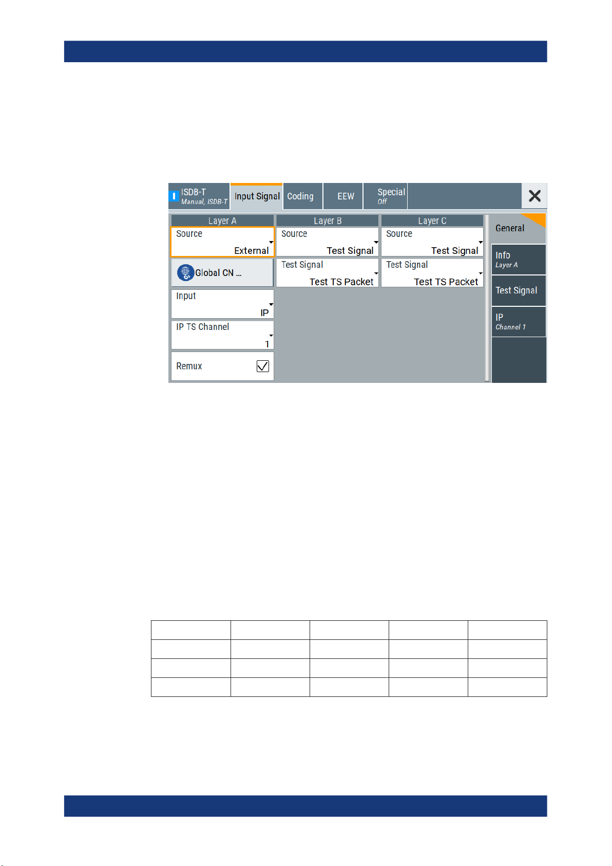
3.2.1 General settings
Access:
► Select "Input Signal > General".
ISDB-T configuration and settings
Input signal settings
The tab provides general settings to configure the input signal.
Settings:
Source (A|B|C).............................................................................................................. 15
Input.............................................................................................................................. 16
Input Format..................................................................................................................16
IP TS Channel...............................................................................................................16
Test Signal (A|B|C)........................................................................................................17
Remux...........................................................................................................................17
Source (A|B|C)
Sets the modulation source for the input signal.
You can set the modulation source for layer A, B or C. If "Control > Manual", you can
only transmit data in one layer as described in Table 3-1. The table also includes test
signal/PRBS data.
Table 3-1: Data transmission per layer
Layer Pattern 1 Pattern 2 Pattern 3 Pattern 4
A Test/PRBS Data Test/PRBS Test/PRBS
B Test/PRBS Test/PRBS Data Test/PRBS
C Test/PRBS Test/PRBS Test/PRBS Data
Example:
If pattern 2 is set and layer B is to be, set to data (pattern 3), the setting of layer B is
first copied to layer A and layer B is set to data.
15User Manual 1179.1006.02 ─ 04

R&S®SMCVB-K165
ISDB-T configuration and settings
Input signal settings
"External"
"TS Player"
"Test Signal"
Remote command:
[:SOURce<hw>]:BB:ISDBt:SOURce:A on page 61
[:SOURce<hw>]:BB:ISDBt:SOURce:B on page 61
[:SOURce<hw>]:BB:ISDBt:SOURce:C on page 61
Uses a transport stream, that is input at the "TS IN"/"IP Data" interface.
For more information about connecting to the interfaces, see also:
●
"TS IN" interface: Section "Configuring the Global Connectors" in
the R&S SMCV100B user manual.
●
"IP Data" interface: Chapter 3.8, "Local IP data network settings",
on page 48.
Uses an internal transport stream with TS packet data played from a
file. The player requires no option.
Playing encrypted files with extension _c requires a stream library
option R&S SMCVB-KSx.
See also:
●
Chapter 3.7, "TS player", on page 38
●
Supported TS player file types
Uses an internal test signal as specified in Chapter 3.2.3, "Test signal
settings", on page 20.
Input
Requires "Source (A|B|C) > External".
Sets the external input interface.
"TS IN"
"IP"
Remote command:
[:SOURce<hw>]:BB:ISDBt:INPut on page 62
Input Format
Requires "Input > TS IN".
Sets the format of the input signal.
"ASI"
"SMPTE 310"
Remote command:
[:SOURce<hw>]:BB:ISDBt:INPut:FORMat on page 62
IP TS Channel
Requires "Input > IP".
Selects the IP-based transport stream (TS) channel. You can select 1 out of 4 IP TS
channels as input at the "IP Data" interface.
To configure a particular channel, see Chapter 3.2.4, "IP channel x settings",
on page 22.
Input for serial transport stream data. The signal is input at the "User
1" connector.
Input for IP-based transport stream data (TSoverIP). The signal is
input at the "IP Data" connector.
ASI format
SMPTE 310 format
16User Manual 1179.1006.02 ─ 04

R&S®SMCVB-K165
Remote command:
[:SOURce<hw>]:BB:ISDBt:INPut:TSCHannel on page 62
Test Signal (A|B|C)
Requires "Source (A|B|C) > Test Signal".
Defines the test signal data.
"Test TS Packet"
"PRBS before Conv. Enc."
"PRBS after Conv. Enc."
Remote command:
[:SOURce<hw>]:BB:ISDBt:TESTsignal:A on page 66
[:SOURce<hw>]:BB:ISDBt:TESTsignal:B on page 66
[:SOURce<hw>]:BB:ISDBt:TESTsignal:C on page 66
ISDB-T configuration and settings
Input signal settings
Transmits transport stream packets, that have a set PID, see "PID
(Hex)" on page 21.
A PRBS is inserted into the payload of these packets (MSB first). If
"PID ≠ 1FFF", the continuity counter of these packets is incremented.
PRBS data used as modulation data with no packet structure. The
sequence is inserted before the convolutional encoder. PRBS data
conforms with ITU-T O.151 specification.
To configure the PRBS type, select the side tab "Test Signal >
PRBS". See also "PRBS" on page 22.
PRBS data used as modulation data with no packet structure. The
sequence is inserted after the convolutional encoder.
Remux
Enables/disables the built-in TS remultiplexer.
Enabling requires "Control > Manual". If "Control > Auto", "Remux > Off" is fixed set-
ting.
"On"
"Off"
Remote command:
[:SOURce<hw>]:BB:ISDBt:REMux on page 62
Processes a conventional MPEG-2 transport stream (usual TS).
The remultiplexer operates in accordance with specification ARIB
STD-B31, Appendix, section 3.2 "Multiplexed signals for hierarchical
transmission".
Disabled remultiplexer operation depends on the setting of "Control":
●
"Control > Auto": The ISDB-T encoder processes an already
remultiplexed TS (broadcast TS).
●
"Control > Manual": The remultiplexer processes a conventional
MPEG-2 TS.
17User Manual 1179.1006.02 ─ 04
R&S®SMCVB-K165
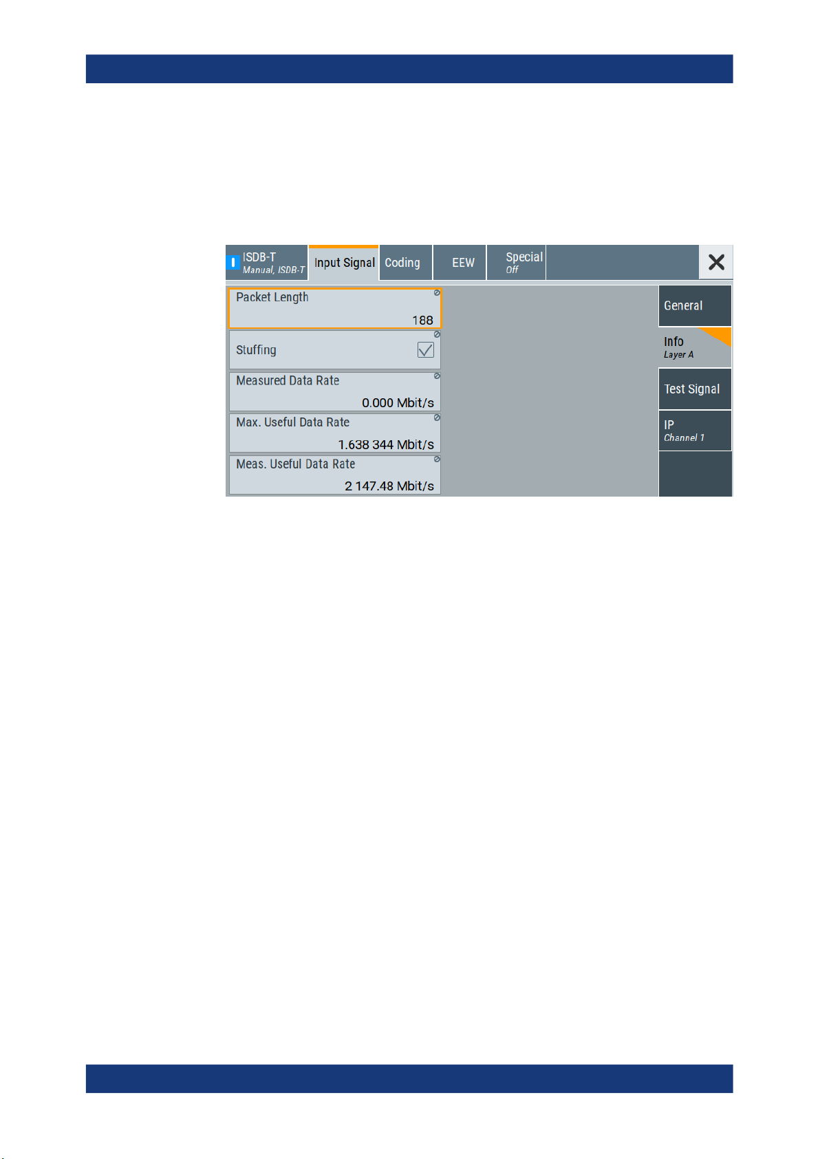
3.2.2 Info
Access:
► Select "Input Signal > Info Layer".
ISDB-T configuration and settings
Input signal settings
The tab displays information on the input signal.
Input signal information
The displayed information comprises common layer settings and layer-specific settings:
●
"Control > Auto": Stuffing state, packet length and measured data rate is displayed
for all layers.
Layer-specific information is displayed for the maximum useful data rate and the
measured useful data rate.
●
"Control > Manual": Displays layer-specific information only.
Information is displayed for the layer, that has a setting "Source > External/TS
Player".
See also "Source (A|B|C)" on page 15.
Settings:
Packet Length............................................................................................................... 18
Stuffing..........................................................................................................................19
Measured Data Rate.....................................................................................................19
Max. Useful Data Rate (A|B|C)..................................................................................... 19
Meas. Useful Data Rate (A|B|C)................................................................................... 20
Packet Length
Requires "Source > External".
Displays the packet length of the external transport stream in bytes.
If the packet length does not match the specified length, the output signal is erroneous.
"Packet Length > Invalid" is displayed.
18User Manual 1179.1006.02 ─ 04

R&S®SMCVB-K165
ISDB-T configuration and settings
Input signal settings
"188"
"204"
"Invalid"
188 byte packets specified for serial input and parallel input.
204 byte packets specified for serial input and parallel input.
Packet length ≠ 188 bytes, 204 bytes or 208 bytes, i.e. the length is
not as specified.
Remote command:
[:SOURce<hw>]:BB:ISDBt:PACKetlength? on page 63
Stuffing
Requires the following:
●
"System > ISDB-T", see "System" on page 13.
●
"Source > External/TS Player"
Displays, if stuffing is enabled or disabled.
You can enable/disable stuffing by setting "ISDB-T > Control":
●
"Control > Auto" disables stuffing.
●
"Control > Manual" enables stuffing.
Example: Transport stream stuffing
1. All MPEG-2 null packets are removed.
2. MPEG-2 null packets are added into the transport stream increasing the desired
data rate.
3. Simultaneously, PCR values are corrected.
Remote command:
[:SOURce<hw>]:BB:ISDBt:STUFfing? on page 62
Measured Data Rate
Displays the measured value of the data rate r
●
External transport stream including null packets input at "User 1" connector
●
External transport stream including null packets input at "IP Data/LAN" connector
of one of the following:
meas
(TSoverIP)
The value r
r
= r
meas
useful
equals the sum of useful data rate r
meas
+ r
0
and the rate of null packets r0:
useful
Remote command:
[:SOURce<hw>]:BB:ISDBt[:INPut]:DATarate? on page 64
Max. Useful Data Rate (A|B|C)
Displays the transport stream data rate that is derived from the current modulation
parameter settings. The value is the optimal value at the TS input interface, that is necessary for the modulator.
If "Control > Auto", the tab also displays the maximum useful data rate for the specific
layer.
Remote command:
[:SOURce<hw>]:BB:ISDBt:USEFul[:RATE]:MAX:A? on page 64
[:SOURce<hw>]:BB:ISDBt:USEFul[:RATE]:MAX:B? on page 64
[:SOURce<hw>]:BB:ISDBt:USEFul[:RATE]:MAX:C? on page 64
19User Manual 1179.1006.02 ─ 04
R&S®SMCVB-K165
Meas. Useful Data Rate (A|B|C)
Displays the data rate measured in the specific layer.
If the measured data rate exceeds the maximum permissible data rate ("Max. Useful
Data Rate (A|B|C)"), an overflow occurs. Data losses can occur during transmission.
Remote command:
[:SOURce<hw>]:BB:ISDBt:USEFul[:RATE]:A? on page 64
[:SOURce<hw>]:BB:ISDBt:USEFul[:RATE]:B? on page 64
[:SOURce<hw>]:BB:ISDBt:USEFul[:RATE]:C? on page 64
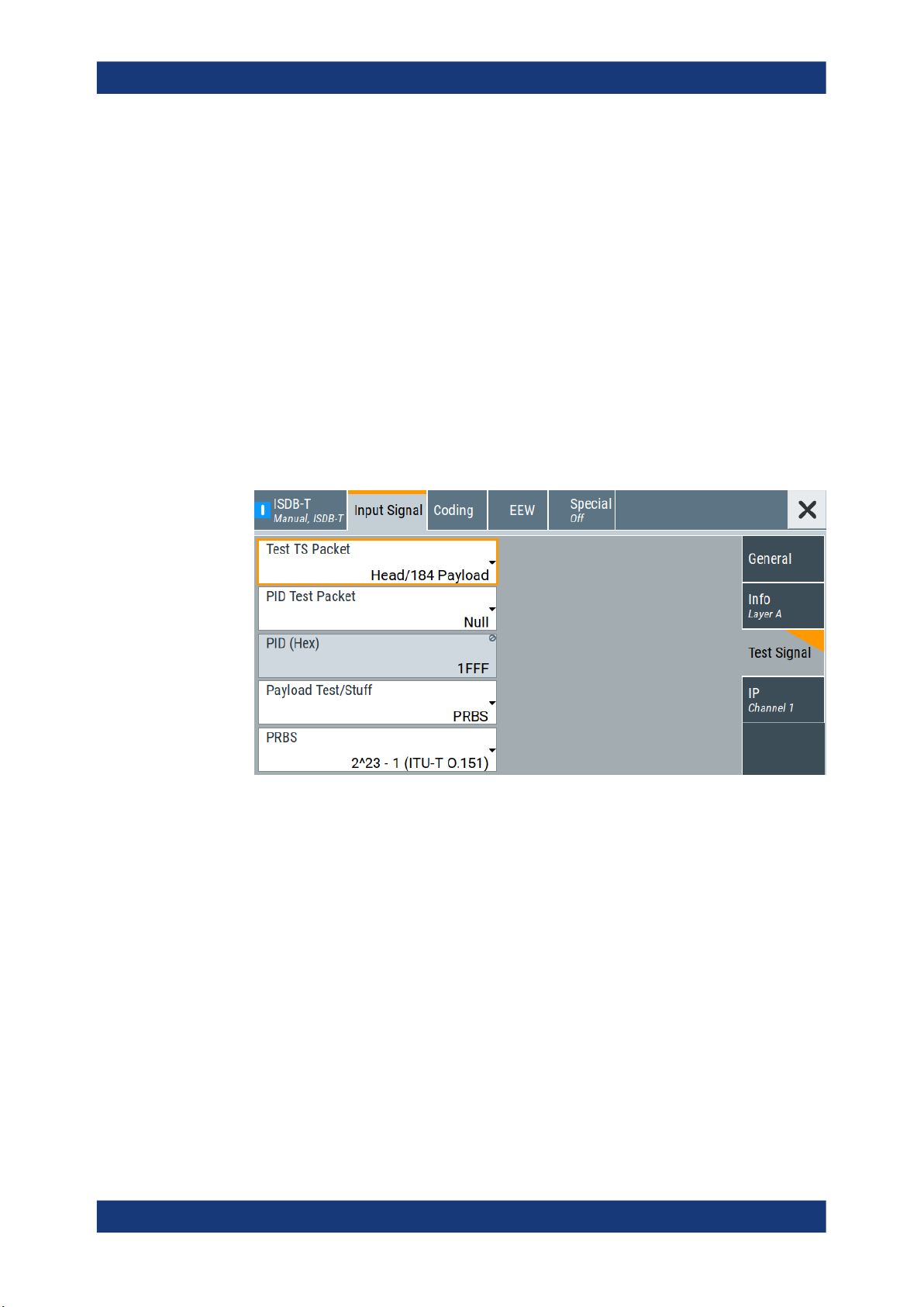
3.2.3 Test signal settings
Access:
► Select "Input Signal > Test Signal".
ISDB-T configuration and settings
Input signal settings
The tab provides settings to configure the input test signal.
Settings:
Test TS Packet..............................................................................................................20
PID Test Packet.............................................................................................................21
PID (Hex)...................................................................................................................... 21
Payload Test/Stuff......................................................................................................... 22
PRBS............................................................................................................................ 22
Test TS Packet
Standardized packet data used as modulation data in the transport stream. To configure the packet structure, select the side tab "Test Signal > Test TS Packet".
Set the content of the payload area via "Payload Test/Stuff" on page 22.
Note: According to the ISDB-T standard, the PAT, NIT and CAT MPEG-2 tables have
to be transmitted on the most robust hierarchical layer. For PMT and PCR packets,
special transmission rules have to be applied also.
20User Manual 1179.1006.02 ─ 04

R&S®SMCVB-K165
For details see specification ARIB STD-B31, "Appendix: Operation guidelines for Digital terrestrial television broadcasting". The following example shows the impact on the
bit error rate measurement:
Example:
Assume a transmission system with three layers. Layer A is fed with an external transport stream, layers B and C are fed with test TS packets. Layer C is configured as the
most robust layer. In this configuration, some MPEG-2 tables are also transmitted on
layer C. This means that not all transport stream packets of layer C carry the PRBS,
but some packets carry MPEG-2 tables. The BER tester has to apply a PID filter to find
the wanted packets. In consequence, "Sync/187 Payload" cannot be used, because
there is no PID available in this setting. In contrast, the content of layer B stays
untouched and can be evaluated without a PID filter.
"Head/184 Payload"
"Sync/187 Payload"
Remote command:
[:SOURce<hw>]:BB:ISDBt:TSPackets:A on page 67
ISDB-T configuration and settings
Input signal settings
A sync byte (0x47) followed by three header bytes and 184 payload
bytes.
A sync byte (0x47) followed by 187 payload bytes.
PID Test Packet
If a header is present in the test packet ("Test TS Packet > Head/184 Payload"), you
can specify a fixed or variable packet identifier (PID).
"Null"
The header of the test transport stream packets has a fixed setting of
null packet header 1FFF (hex).
"Variable"
Uses the header value defined with PID (Hex).
Remote command:
[:SOURce<hw>]:BB:ISDBt:PIDTestpack on page 66
PID (Hex)
Sets the PID.
If "PID Test Packet > Variable", you can define the PIDs for each layer as follows:
●
Layer A: PID a range = "0" to "1FFF"
●
Layer B: PID B range = (PID A + 1) mod1) 0x2000
●
Layer C: PID C range = (PID A + 2) mod1) 0x2000
1)
mod = modulo operator
Table 3-2: PID example calculations
PID A PID B PID C
0x1FFD 0x1FFE 0x1FFF
0x1FFE 0x1FFF 0x0000
0x1FFF 0x0000 0x0001
0x0000 0x0001 0x0002
21User Manual 1179.1006.02 ─ 04
R&S®SMCVB-K165
Remote command:
[:SOURce<hw>]:BB:ISDBt:PID on page 66
Payload Test/Stuff
Defines the payload area content of the TS packet.
The TS packet is the test signal "Test TS Packet" or a null packet.
If "Source > Test Signal", the packet is a test packet.
If "Stuffing > On", the packet is a null packet. Null packets are inserted into the external
transport stream to adapt the stream data rate. The rate is adapted to a value, that fits
the current modulation parameter settings.
"PRBS"
"0x00"
ISDB-T configuration and settings
Input signal settings
PRBS data in accordance with ITU-T O.151
Exclusively 00 (hex) data
"0xFF"
Remote command:
[:SOURce<hw>]:BB:ISDBt:PAYLoad:A on page 65
PRBS
Sets the length of the PRBS sequence.
You can select a PRBS 15 or a PRBS 23 sequence as specified by ITU-T O.151.
Remote command:
[:SOURce<hw>]:BB:ISDBt:PRBS[:SEQuence] on page 66
Exclusively FF (hex) data
3.2.4 IP channel x settings
Access:
1. Select "Input Signal > General".
2. Select "Source > External"
3. Select "Input > IP"
4. Select "Input Signal > IP Channel x"
22User Manual 1179.1006.02 ─ 04

R&S®SMCVB-K165
You can configure settings for 4 IP channels x = 1 to 4 individually, see also "Input
Signal > General > IP TS Channel".
IP channel settings affect input IP data of the local IP data network. The settings are
independent from the used broadcast standard configuration.
Saving/recalling a certain IP channel or local IP data network configuration is not possible via the broadcast standard-specific functionality.
Use the global save/recall functionality instead, see section "Saving and Recalling
Instrument Settings" in the R&S SMCV100B user manual.
The table below shows the availability of the tab in the broadcast standard configuration.
Table 3-3: IP channel configuration support in broadcast standards
ISDB-T configuration and settings
Input signal settings
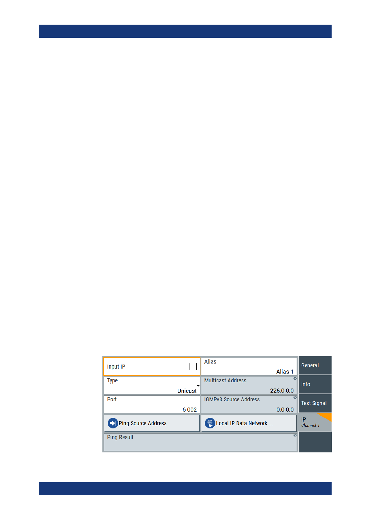
The tab provides settings to configure IP channel x.
Baseband standard "IP Channel x" Baseband standard "IP Channel x"
"ATSC/ATSC-M/H" Yes "DVB-S" Yes
"ATSC 3.0" No "DVB-S2" Yes
"DTMB" Yes "DVB-C" Yes
"DVB-T" Yes "J.83/B" Yes
"DVB-T2" Yes "DRM" No
"ISDB-T" Yes "Audio AM" No
"T-DMB/DAB" Yes "Audio FM" No
See also:
●
Chapter 4.1.1, "How to apply an external IP input signal", on page 51
●
Chapter 3.8, "Local IP data network settings", on page 48
Requirements
At your IP source, set the "transport stream packets per internet protocol packet" (TP
per IP) parameter as follows:
●
If TP packet length = 188 bytes: Set TP per IP to 7 or 6.
●
If TP packet length = 204/208 bytes: Set TP per IP to 6.
We recommend that you use a separate LAN infrastructure to stream the transport
streams via IP to the IP connector of the baseband board. Also, avoid TS packet losses during IP transmission.
Settings:
Input IP..........................................................................................................................24
Alias.............................................................................................................................. 24
Type.............................................................................................................................. 24
Multicast Address..........................................................................................................24
23User Manual 1179.1006.02 ─ 04

R&S®SMCVB-K165
Port................................................................................................................................24
IGMPv3 Source Address...............................................................................................24
Ping Source Address.................................................................................................... 25
Ping Result....................................................................................................................25
Local IP Data Network.................................................................................................. 25
Input IP
Activates/deactivates the IP input.
Remote command:
[:SOURce<hw>]:BB:INPut:IP<ch>[:STATe] on page 68
Alias
Sets a unique name for the IP connection.
The definition of a name is optional but facilitates identification in the measurement
views. The name input fits maximum 16 characters in ASCII format.
Remote command:
[:SOURce<hw>]:BB:INPut:IP<ch>:ALIas on page 68
ISDB-T configuration and settings
Input signal settings
Type
Sets the input signal type.
"Unicast"
"Multicast"
Remote command:
[:SOURce<hw>]:BB:INPut:IP<ch>:TYPE on page 69
Multicast Address
Editing requires "Type > Multicast".
Sets the destination IP address (IPv4) of the IP connection.
You can set addresses from "224.0.0.0" to "239.255.255.255".
Remote command:
[:SOURce<hw>]:BB:INPut:IP<ch>:MULticast:ADDRess on page 69
Port
Sets the destination UDP port.
Due to UDP/RTP autosensing, we recommend that you set a port offset of at least 6
between neighboring IP TS channels.
Remote command:
[:SOURce<hw>]:BB:INPut:IP<ch>:PORT on page 68
Analyzes all unicast IP packets that arrive at the specified "Port".
When an IP address is in the multicast address range, an attempt is
made to join a multicast group using IGMP.
Set "Multicast Address" and "Port".
IGMPv3 Source Address
Requires "Type > Multicast".
Sets the IGMPv3 source address.
24User Manual 1179.1006.02 ─ 04

R&S®SMCVB-K165
If you need to filter the data sent to the multicast address, specify the source address.
A source address different from "0.0.0.0" accepts only data originating from the specified IP address.
Remote command:
[:SOURce<hw>]:BB:INPut:IP<ch>:IGMP[:SOURce]:ADDRess on page 69
Ping Source Address
Clicking "Ping Source Address" triggers pinging of the IGMPv3 source address.
If you set a different value from "IGMPv3 Source Address = 0.0.0.0" and click the but-
ton, the software checks if the address is reachable.
Remote command:
[:SOURce<hw>]:BB:INPut:IP<ch>:IGMP[:SOURce]:PING on page 70
Ping Result
Displays the result after pinging the source address.
If "Ping Result > Ping: Successful", the source address is available in the network.
If "Ping Result > Ping: Transmit Failed. xxx", the source address is not available in the
network. "xxx" can be, e.g. "General Failure". Try another "IGMPv3 Source Address".
Remote command:
[:SOURce<hw>]:BB:INPut:IP<ch>:IGMP[:SOURce]:RESult? on page 70
ISDB-T configuration and settings
Coding settings
Local IP Data Network
Accesses local IP data network settings, see Chapter 3.8, "Local IP data network set-
tings", on page 48.
3.3 Coding settings
Access:
► Select "Baseband > ISDB-T/TSB > Coding".
The tab provides settings for coding of one or two input paths.
Editing most of the coding parameters requires "Control > Manual". If "Control > Auto",
the ISDB-T encoder extracts the information from the TS. Relevant parameters display
the coding information from the stream.
Settings:
● General settings......................................................................................................26
● System settings.......................................................................................................29
25User Manual 1179.1006.02 ─ 04
R&S®SMCVB-K165
3.3.1 General settings
Access:
► Select "Coding > General".
ISDB-T configuration and settings
Coding settings
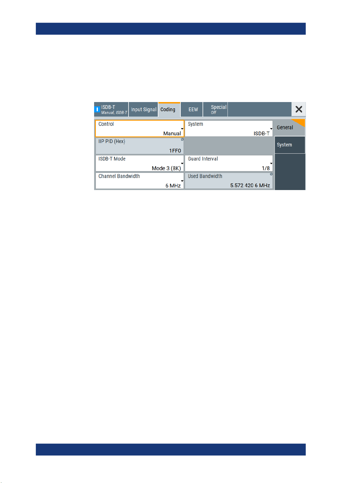
The tab provides general coding settings.
Settings:
Control...........................................................................................................................26
System.......................................................................................................................... 26
IIP PID (Hex).................................................................................................................27
ISDB-T Mode................................................................................................................ 27
Guard Interval............................................................................................................... 27
Subchannel................................................................................................................... 27
Channel Bandwidth.......................................................................................................28
Used Bandwidth............................................................................................................28
Control
Defines the configuration mode of the coder.
"Auto"
"Manual"
Remote command:
[:SOURce<hw>]:BB:ISDBt:CONTrol on page 71
System
Sets the ISDB-T system.
ISDB-TSB (see ISDB-TSB) utilizes the same structure of OFDM segments as ISDB-T.
However, the number of segments is different.
"ISDB-T"
"ISDB-TSB (1 SEG)"
The coder is configured by the transport stream.
The coder is configured manually.
13 segments. You can set the number of hierarchical layers.
See " Segments (A|B|C)" on page 30.
1 segment and 1 hierarchical layer.
26User Manual 1179.1006.02 ─ 04

R&S®SMCVB-K165
"ISDB-TSB (3 SEG)"
Remote command:
[:SOURce<hw>]:BB:ISDBt:SYSTem on page 72
IIP PID (Hex)
Requires "Control > Auto".
Defines the PID for MPEG TS packets, that contain ISDB-T initialization packet (IIP)
data.
Remote command:
[:SOURce<hw>]:BB:ISDBt:IIP:PID on page 72
ISDB-T Mode
Sets the ISDB-T mode.
The setting is not layer-specific, but applies to the entire transmission. Use the mode,
e.g., to select the length of the IFFT, that affects the OFDM symbol duration.
Also, the setting affects time interleaving, see "Time Interleaving (A|B|C)" on page 31.
"Mode 1 (2K)"
ISDB-T configuration and settings
Coding settings
3 segments and 2 hierarchical layers.
Implies IFFT length of 2K
"Mode 2 (4K)"
"Mode 3 (8K)"
Remote command:
[:SOURce<hw>]:BB:ISDBt:FFT:MODE on page 71
Guard Interval
Sets the guard interval length.
The guard interval is a cyclic extension of the OFDM symbol by factor "1/4", "1/8",
"1/16" or "1/32".
Disable the guard interval via Segments (A|B|C), so that only the useful component of
OFDM symbols is transmitted continuously.
Example: Selecting the guard interval length
The guard interval length affects the receiving characteristics, that are influenced by
multipath propagation:
Using a large guard interval, you can eliminate long echo delays.
Using a small guard interval, the echoes of an OFDM symbol can emit into the OFDM
symbol that follows.
Remote command:
[:SOURce<hw>]:BB:ISDBt:GUARd on page 72
Implies IFFT length of 4K
Implies IFFT length of 8K
Subchannel
Requires "System > ISDB-TSB (1 SEG)/" or ISDB-TSB (3 SEG).
Sets the subchannel of the ISDB-TSB signal.
Specification ARIB STD-B29 defines 42 subchannels within a 6 MHz RF channel. Each
subchannel has a width of 1/7 MHz.
27User Manual 1179.1006.02 ─ 04

R&S®SMCVB-K165
One OFDM segment comprises three subchannels. The parameter defines the center
subchannel of the center OFDM segment. The RF frequency is not modified. The subchannel determines the initial value of the Wi PRBS register. See specification ARIB
STD-B29, chapter 3.13.1.
Remote command:
[:SOURce<hw>]:BB:ISDBt:SUBChannel on page 72
Channel Bandwidth
Selects the channel bandwidth.
The channel bandwidth correlates with the "Used Bandwidth", that is smaller. For the
correlation between the two bandwidths, see .
As the number of the OFDM carriers remains constant, the carrier spacing and the
OFDM symbol duration are adapted accordingly.
Remote command:
[:SOURce<hw>]:BB:ISDBt:CHANnel[:BANDwidth] on page 71
Used Bandwidth
Displays the used bandwidth.
The value depends on ISDB-T mode and the channel bandwidth. If you change the
ISDB-T mode, the used bandwidth value adapts automatically. The correlation is
shown in Table 3-4, where:
●
●
Table 3-4: ISDB-T mode and used bandwidth at constant channel bandwidths
Δf
Δf
: Channel bandwidth
Channel
: Used bandwidth
Used
ISDB-T configuration and settings
Coding settings
ISDB-T mode Δf
"Mode 1 (2K)" Δf
"Mode 2 (4K)" (Δf
"Mode 3 (8K)" Δf
= 6 MHz Δf
Channel
= (39000 / 7 + 250 /
Used
63) kHz ≈ 5.575397 MHz
= 39000 / 7 + 125 /
Used
63) kHz ≈ 5.573413 MHz
= (39000 / 7 + 125 /
Used
126) kHz ≈ 5.572421 MHz
= 7 MHz Δf
Channel
Δf
≈ 6.504630 MHz Δf
Used
Δf
≈ 6.502315 MHz Δf
Used
Δf
≈ 6.501157 MHz Δf
Used
Remote command:
[:SOURce<hw>]:BB:ISDBt:BANDwidth? on page 71
= 8 MHz
Channel
≈ 7.433862 MHz
Used
≈ 7.431217 MHz
Used
≈ 7.429894 MHz
Used
28User Manual 1179.1006.02 ─ 04

R&S®SMCVB-K165
3.3.2 System settings
Access:
► Select "Coding > System".
ISDB-T configuration and settings
Coding settings
The tab provides coding system settings.
Settings:
Portion (A|B|C).............................................................................................................. 29
Constellation (A|B|C).....................................................................................................30
Segments (A|B|C)......................................................................................................... 30
Code Rate (A|B|C)........................................................................................................ 30
Time Interleaving (A|B|C)..............................................................................................31
Portion (A|B|C)
Requires "System > ISDB-T".
Sets the modulation types of the respective hierarchical layers.
As specification ARIB STD-B31 does not allow all combinations, an automatic correc-
tion is applied.
"Partial Reception"
Only available for layer A.
"Differential Modulation"
Only available for layer B and C, if layer A ≠ "Coherent Modulation".
"Coherent Modulation"
If selected for layer A, layer B and layer C are automatically set to this
value, too.
Remote command:
[:SOURce<hw>]:BB:ISDBt:PORTion on page 74
29User Manual 1179.1006.02 ─ 04

R&S®SMCVB-K165
Constellation (A|B|C)
Defines the constellation.
The constellation value depends on the portion as Table 3-5 illustrates. If you set a por-
tion and the set constellation is not possible, the constellation adjusts automatically.
Table 3-5: Portion and constellation restrictions
Remote command:
[:SOURce<hw>]:BB:ISDBt:CONStel:A on page 73
[:SOURce<hw>]:BB:ISDBt:CONStel:B on page 73
[:SOURce<hw>]:BB:ISDBt:CONStel:C on page 73
Segments (A|B|C)
Sets the number of segments for layers A, B and C.
The number depends on the ISDB-T system:
●
●
To disable a layer, assign it zero segments. Layer A cannot be disabled. Layer B can
only be disabled if layer C has been disabled. Layer C can only be enabled if layer B
has been enabled.
If "Portion (A|B|C) > Partial Reception", it is always on layer A, which is assigned
exactly one segment.
Remote command:
[:SOURce<hw>]:BB:ISDBt:SEGMents:A on page 74
[:SOURce<hw>]:BB:ISDBt:SEGMents:B on page 74
[:SOURce<hw>]:BB:ISDBt:SEGMents:C on page 74
ISDB-T configuration and settings
Coding settings
"Portion" Constellation
"Partial Reception" DQPSK, QPSK, 16QAM, 64QAM
"Differential Modulation" DQPSK
"Coherent Modulation" QPSK, 16QAM, 64QAM
If "System > ISDB-T", assigns the desired number of segments to each of the 3
layers. The sum of all segments is always 13.
If "System > ISDB-TSB (1 SEG)/ISDB-TSB (3 SEG)", you cannot set the number of
segments per hierarchical layer. The following setting is fixed:
" Segments (A) > 1", " Segments (B) > 2"
Code Rate (A|B|C)
Sets the code rate.
You can define the code rate of the convolutional coders of each layer separately. The
setting affects the maximum data rate of the respective layer, see "Max. Useful Data
Rate (A|B|C)" on page 19.
If you transmit more useful data, i.e. if less redundancy is inserted, troubleshooting
becomes more difficult. If you transmit less useful data, transmission reliability is
higher.
30User Manual 1179.1006.02 ─ 04
 Loading...