


NFC A/B/F
Digital Standard for
R&S®Signal Generators
Operating Manual
(;ÙÖÒ2)
1175.7268.02 ─ 10
Operating Manual
Test & Measurement

This document describes the following software options:
●
R&S®SMBV-K89
1419.1654.02
●
R&S®AMU-K89
1403.1037.02
●
R&S®SMATE-K89
1404.8906.02
●
R&S®SMJ-K89
1409.3602.02
●
R&S®SMU-K89
1408.8730.02
This manual version corresponds to firmware version:
FW 3.50.082.xx and later of the R&S®SMBV100A
FW 3.20.286.xx and later of the R&S®SMU200A, R&S®SMATE200A, R&S®SMJ100A and R&S®AMU200A
© 2016 Rohde & Schwarz GmbH & Co. KG
Mühldorfstr. 15, 81671 München, Germany
Phone: +49 89 41 29 - 0
Fax: +49 89 41 29 12 164
Email: info@rohde-schwarz.com
Internet: www.rohde-schwarz.com
Subject to change – Data without tolerance limits is not binding.
R&S® is a registered trademark of Rohde & Schwarz GmbH & Co. KG.
NFC ForumTM and the NFC Forum logo are trademarks of the Near Field Communication Forum.
EMVTM is a registered trademark in the U.S. and other countries and an unregistered trademark elsewhere. The EMVTM trademark is
owned by EMVCo LLC.
Trade names are trademarks of the owners.
The following abbreviations are used throughout this manual: NFC ForumTM is abbreviated as NFC Forum, EMVTM is abbreviated as
EMV, R&S®SMBV100A is abbreviated as R&S SMBV, R&S®SMU200A is abbreviated as R&S SMU, R&S®AMU200A is abbreviated
as R&S AMU, R&S®SMATE200A is abbreviated as R&S SMATE, R&S®SMJ100A is abbreviated as R&S SMJ, R&S®WinIQSIM2TM is
abbreviated as R&S WinIQSIM2; the license types 02/03/07/11/13/16/12 are abbreviated as xx.

ContentsNFC A/B/F
Contents
1 Preface.................................................................................................... 5
2 About the NFC Digital Standard........................................................... 9
3 About the EMV Contactless Digital Standard....................................19
4 User Interface....................................................................................... 21
5 How to Generate Signals with the NFC A/B/F Option.......................63
6 Remote-Control Commands............................................................... 67
Glossary: List of the Often Used Terms and Abbreviations.......... 117
List of Commands..............................................................................123
Index....................................................................................................128
3Operating Manual 1175.7268.02 ─ 10

ContentsNFC A/B/F
4Operating Manual 1175.7268.02 ─ 10

1 Preface
PrefaceNFC A/B/F
Documentation Overview
1.1 Documentation Overview
This section provides an overview of the R&S Signal Generator user documentation.
You find it on the product page at:
http://www.rohde-schwarz.com/product/SMBV100A.html > "Downloads"
Quick start guide
Introduces the R&S Signal Generator and describes how to set up and start working
with the product. Includes basic operations, typical measurement examples, and general information, e.g. safety instructions, etc. A printed version is delivered with the
instrument.
Online help
Offers quick, context-sensitive access to the complete information for the base unit and
the software options directly on the instrument.
Operating manual
Separate manuals for the base unit and the software options are provided for download:
●
Base unit manual
Contains the description of all instrument modes and functions. It also provides an
introduction to remote control, a complete description of the remote control commands with programming examples, and information on maintenance, instrument
interfaces and error messages. Includes the contents of the quick start guide manual.
●
Software option manual
Contains the description of the specific functions of an option. Basic information on
operating the R&S Signal Generator is not included.
The online version of the operating manual provides the complete contents for immediate display on the Internet.
Service manual
Describes the performance test for checking the rated specifications, module replacement and repair, firmware update, troubleshooting and fault elimination, and contains
mechanical drawings and spare part lists.
The service manual is available for registered users on the global Rohde & Schwarz
information system (GLORIS, https://gloris.rohde-schwarz.com).
5Operating Manual 1175.7268.02 ─ 10
PrefaceNFC A/B/F
Conventions Used in the Documentation
Instrument security procedures manual
Deals with security issues when working with the R&S Signal Generator in secure
areas.
Basic safety instructions
Contains safety instructions, operating conditions and further important information.
The printed document is delivered with the instrument.
Data sheet and brochure
The data sheet contains the technical specifications of the software options, see "Digital Standards for Signal Generators - Data sheet" on the web site. It also lists the
options and their order numbers.
The brochure provides an overview of the instrument and deals with the specific characteristics.
Release notes and open source acknowledgment (OSA)
The release notes of the base units list new features, improvements and known issues
of the current firmware version, and describe the firmware installation.
The open source acknowledgment document provides verbatim license texts of the
used open source software. See the product page of the base unit, e.g. at:
http://www.rohde-schwarz.com/product/SMBV100A.html > "Downloads" > "Firmware"
Application Notes, Application Cards, White Papers, etc.
These documents deal with special applications or background information on particular topics, see http://www.rohde-schwarz.com/appnotes.
1.2 Conventions Used in the Documentation
1.2.1 Typographical Conventions
The following text markers are used throughout this documentation:
Convention Description
"Graphical user interface elements"
KEYS Key names are written in capital letters.
File names, commands,
program code
Input Input to be entered by the user is displayed in italics.
All names of graphical user interface elements on the screen, such as
dialog boxes, menus, options, buttons, and softkeys are enclosed by
quotation marks.
File names, commands, coding samples and screen output are distinguished by their font.
6Operating Manual 1175.7268.02 ─ 10
PrefaceNFC A/B/F
Conventions Used in the Documentation
Convention Description
Links Links that you can click are displayed in blue font.
"References" References to other parts of the documentation are enclosed by quota-
tion marks.
1.2.2 Notes on Screenshots
When describing the functions of the product, we use sample screenshots. These
screenshots are meant to illustrate as much as possible of the provided functions and
possible interdependencies between parameters. The shown values may not represent
realistic test situations.
The screenshots usually show a fully equipped product, that is: with all options installed. Thus, some functions shown in the screenshots may not be available in your particular product configuration.
1.2.3 Naming of Software Options
In this operating manual, we explicitly refer to options required for specific functions of
the digital standard.
The name of software options for signal generators vary in the name of the instrument,
but the option name is identical. Therefore we use in this manual the placeholder
R&S SMx/AMU.
Example:
Naming for an option of the vector signal generator R&S SMBV100A, e.g:
●
R&S SMx/AMU-K99, stands for R&S SMBV-K99
The particular software options available for the corresponding instruments are listed
on the back of the title page.
7Operating Manual 1175.7268.02 ─ 10

PrefaceNFC A/B/F
Conventions Used in the Documentation
8Operating Manual 1175.7268.02 ─ 10

About the NFC Digital StandardNFC A/B/F
Basics of Data Transmission with NFC
2 About the NFC Digital Standard
The following description is taken from the R&S White Paper 1MA182: "Near Field
Communication (NFC) Technology and Measurements" which contains further practical hints.
Near Field Communication (NFC) is a new, short-range wireless connectivity technology that evolved from a combination of existing contactless identification and interconnection technologies. It was jointly developed by Sony and NXP Semiconductors (formerly Philips).
NFC is designed to enable the exchange of various types of information, such as telephone numbers, pictures, MP3 files or digital authorizations between two NFC enabled
devices like mobile phones, or between an NFC enabled mobile phone and a compatible RFID chip card or reader that are held close to each other. NFC is intended to be
used as an access key to contents and for services such as cashless payment, ticketing and access control.
NFC operates in a frequency range centered on 13.56 MHz and offers a data transmission rate of up to 424 kbit/s within a distance of approximately 10 centimeters. In contrast to the conventional contactless technology in this frequency range (only activepassive communications), communications between NFC-capable devices can be
active-active (peer-to-peer) as well as active-passive, NFC therefore represents a link
to the RFID world. NFC is backwards compatible with the widely used Smart Card
infrastructure based on ISO/IEC 14443 A (e. g. NXP's MIFARE technology) and
ISO/IEC 14443 B as well as with the Sony FeliCa card (JIS X 6319-4). For the
exchange of information between two NFC devices, a new protocol was developed
which is defined in the standards ECMA-340 and ISO/IEC 18092.
To guarantee the function of NFC devices conforming to the standards as well as comprehensive protocol tests, a number of RF tests also have to be carried out. An NFC
generator is an essential part of these tests. The option R&S SMx/AMU-K89 enables
you to generate signals in accordance with the NFC standard.
The NFC specific abbreviations used in this manual as well as the different types of tag
platforms/protocols (e.g. Type 4A Tag, NFC-DEP) are described in the NFC Digital
Protocol Technical Specification. All mentioned standards are available under
www.nfc-forum.org.
2.1 Basics of Data Transmission with NFC
Like the RFID Standards 14443 and FeliCa NFC uses an inductive coupling. Similar to
the transformer principle, the magnetic near-field of two conductor coils is used to couple the polling device (initiator) and listening device (target).
9Operating Manual 1175.7268.02 ─ 10

About the NFC Digital StandardNFC A/B/F
Basics of Data Transmission with NFC
Figure 2-1: Polling device (initiator) and listening device (target) configuration
The operating frequency is 13.56 MHz, and a bitrate of 106 kbit/s (partly also 212 kbit/s
and 424 kbit/s) is used. Modulation schemes are amplitude on/off keying (OOK) with
different modulation depth (100 % or 10 %) and BPSK.
2.1.1 Power Transmission and Data Transmission from a Polling Device
For transmission to a passive system such as an NFC phone in passive card emulation
mode, the passive system uses the 13.56 MHz carrier signal of the polling device as
energy source. Modulation scheme of the polling device is ASK. For NFC peer-to-peer
mode, both directions are modulated and coded like a polling device. However less
power is necessary because both NFC devices use their own power supply and the
carrier signal is switched off after end of transmission.
2.1.2 Data Transmission from a Listening Device
Due to the coupling of the coils of a polling and a listening device, a passive listening
device also affects the active polling device. A variation in the impedance of the listening device causes amplitude changes to the antenna voltage of the polling device,
detected by the polling device. This technique is called load modulation. Load modulation is carried out in listening mode (as with ISO/IEC 14443) using an auxiliary carrier
at 848 kHz which is modulated by the baseband and varies the impedance of the listening device. The Figure 2-2 shows the spectrum with load modulation. Modulation
spectra of carrier and auxiliary carriers are indicated with triangles (Modulation spectra
of carrier and of auxiliary carriers do not appear at the same time because NFC uses
time division multiplexing). The modulation scheme is ASK (as with ISO/IEC 14443 A
PICC’s) or BPSK as with 14443 B PICC’s. There is a third passive mode which is compatible to FeliCa where the load modulation is without an auxiliary carrier directly as
ASK on the 13.56 MHz carrier.
10Operating Manual 1175.7268.02 ─ 10

About the NFC Digital StandardNFC A/B/F
Basics of Data Transmission with NFC
Figure 2-2: Load modulation on a 13.56 MHz carrier with 848 kHz auxiliary carrier.
2.1.3 Modulation Scheme and Coding
Amplitude shift keying (OOK) with different modulation depths (100% or 10%) or BPSK
(as with ISO/IEC 14443 B PICC’s) is used.
Figure 2-3: ASK with 100% modulation depth
Figure 2-4: ASK with 10% modulation depth
11Operating Manual 1175.7268.02 ─ 10
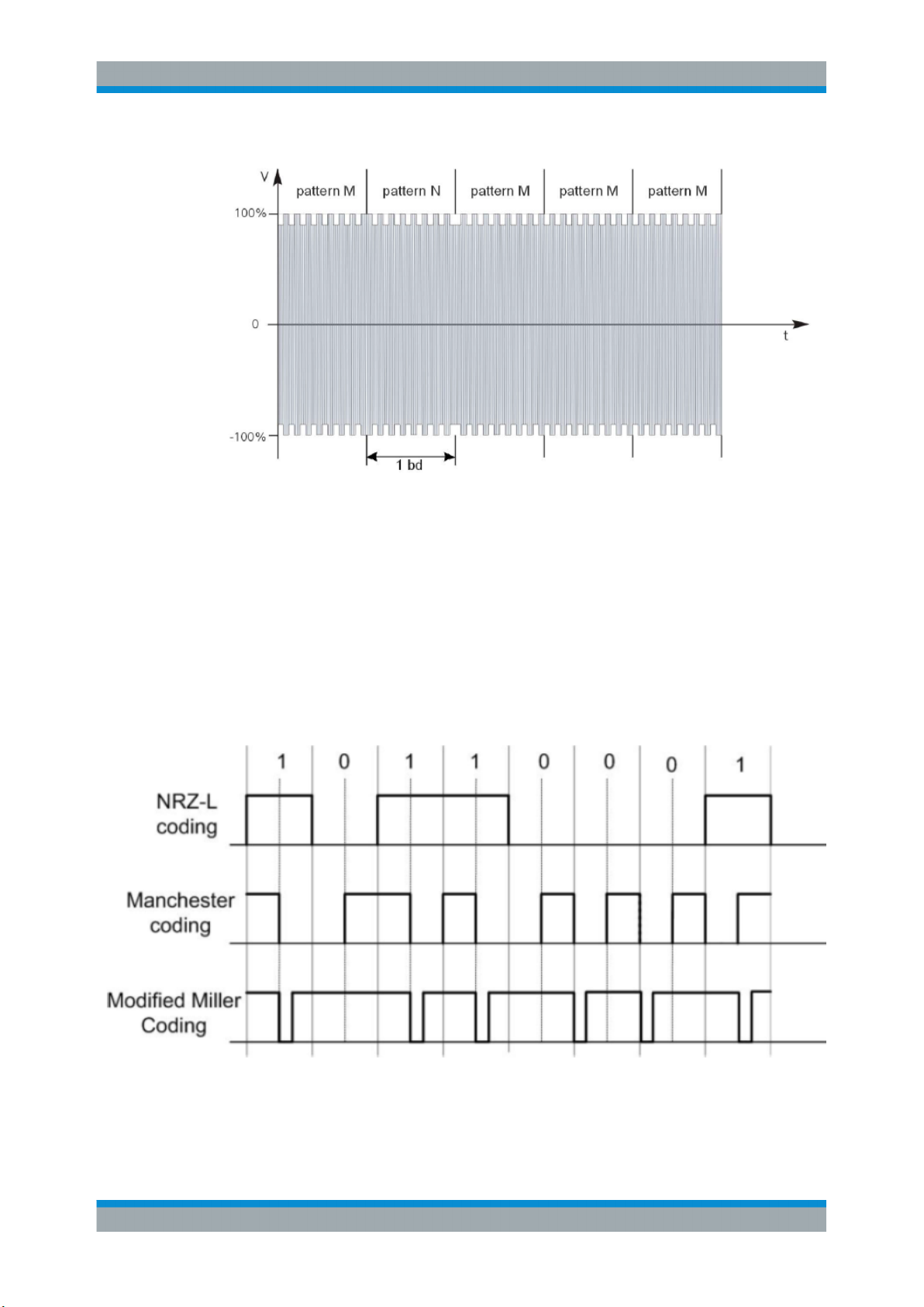
Figure 2-5: NRZ-L Coding with BPSK
About the NFC Digital StandardNFC A/B/F
Basics of Data Transmission with NFC
NRZ-L, Modified Miller and Manchester Coding are used by NFC.
●
With NRZ-L a “high”-state during a bit duration indicates a logic 1, a “low”-state a
logic 0.
●
With Manchester Coding the first half of a bit will be set to “high”-state at a logic 1,
and the second half to “low state”. With a logic 0, the fist half of a bit is set to “low”state and the second half to “high”-state.
●
With Modified Miller Coding with a logic 1 a “low” pulse occurs after half of the bit
duration. With a logic 0 a “low”-pulse occurs at the beginning of a bit. Exception: If
a logic 0 follows a 1 no pulse occurs, the signal remains high.
Figure 2-6: Coding with NFC is either NRZ_L, Modified Miller or Manchester
12Operating Manual 1175.7268.02 ─ 10

About the NFC Digital StandardNFC A/B/F
Basics of Data Transmission with NFC
In Figure 2-7 load modulation is visualized for ASK modulation with Manchester Coding (14443 A PICC or NFC-A device in passive card emulation mode, see Chap-
ter 2.1.4, "NFC Operating Modes, Modulation and Coding", on page 13)
Figure 2-7: Visualisation of load modulation with auxiliary carrier in time and frequency domain
2.1.4 NFC Operating Modes, Modulation and Coding
There are three main operating modes for NFC:
●
Card emulation mode (passive mode): the NFC device behaves like an existing
contactless card conforming to one of the legacy standards
●
Peer-to-peer mode: two NFC devices exchange information. The initiator device
(polling device) requires less power compared to the reader/writer mode because
the target (listener) uses its own power supply.
●
Reader/writer mode (active mode): the NFC device is active and reads or writes to
a passive legacy RFID tag.
Figure 2-8: NFC operating modes
Every mode (card emulation, peer-to-peer, reader/writer mode) can be combined with
one of the following transmission technologies:
●
NFC-A (backward compatible to ISO/IEC 14443 A)
●
NFC-B (backward compatible to ISO/IEC 14443 B)
●
NFC-F (backward compatible to JIS X 6319-4)
13Operating Manual 1175.7268.02 ─ 10
To support all the different technologies, an NFC device in polling mode first attempts
to get responses from NFC-A, NFC-B and NFC-F tags with the according request signals. When getting a response from a compatible device, the NFC device sets up the
corresponding communication mode (NFC-A, NFC-B or NFC-F mode).
Coding and modulation varies depending on active or passive communication mode,
NFC-A, -B, -F communication, and bitrate.
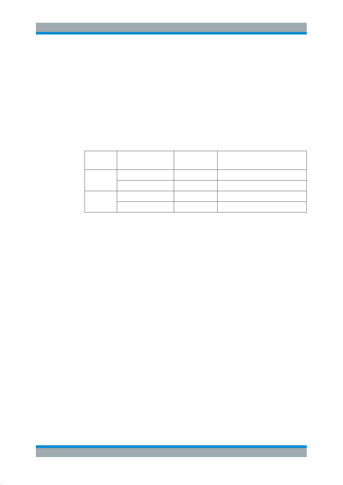
The Table 2-1 shows coding, modulation and data rates for NFC-A, -B or -F communication.
Table 2-1: NFC RF Standards Overview
About the NFC Digital StandardNFC A/B/F
Timing Aspects
NFC Forum
Standard
NFC-A Polling Modified Miller ASK 100% 106 kb/s 13.56 MHz
NFC-B Polling NRZ-L ASK 10% 106 kb/s 13.56 MHz
NFC-F Polling Manchester ASK 10% 212 / 424 kb/s 13.56 MHz
Polling /
Listening
Listening Manchester Load modulation
Listening NRZ-L Load modulation
Listening Manchester Load modulation (APSK) 212 / 424 kb/s 13.56 MHz (without subcarrier)
2.2 Timing Aspects
Coding Modulation Datarate Carrier frequency
106 kb/s 13.56 MHz +-848kHz subcar-
(ASK subcarrier)
106 kb/s 13.56 MHz+-848kHz subcarrier
(BPSK subcarrier)
rier
The NFC specification defines the duration of the individual commands as a number of
bits. This instrument generates the signal as sample sequence where the applied sample rate is user defined. Depending on the selected sampling rate it may be that the
duration of a command expressed in samples does not result in an integer number of
samples. In this implementation however the length of the sequence is always an integer number of samples, i.e. the software rounds up the number of samples to the next
integer value. The rounding up procedure is applied on command basis, even if a command is repeated.
The Figure 2-10 shows this principle as an example.
Example:
The Figure 2-9 shows an example of a sequence with the following settings:
●
Sample Rate = 20.1 Msps
●
Technology > NFC-A
●
Transmission Mode > Poll
Command Type Rep. Duration (µs)
"SENS_REQ" 1 (calculated and displayed automaticaly)
"IDLE" 1 0.05
14Operating Manual 1175.7268.02 ─ 10

About the NFC Digital StandardNFC A/B/F
Timing Aspects
Command Type Rep. Duration (µs)
"ALL_REQ" 2 (calculated and displayed automaticaly)
"BLANK" 1 0.1
Figure 2-9: Example of sequence configuration settings
The Figure 2-10 illustrates the calculation of the Start Time per command and the
parameters Total Sequence Duration and Total Number of Samples.
Figure 2-10: Calculation of duration and number of samples for "Sample Rate" = 20.1 Msps
1 = "Duration" * "Sample Rate" = # Samples, "Samples" = ceil (# Samples)
2 = Duration* = "Samples"/"Sample Rate"
3 = "Start Time"N = (Duration*1 + .. + Duration*
4 = "Total Number of Samples" = "Samples"1 + ... + "Samples"
) = ("Samples"1 + ... + "Samples"
N–1
N
)/"Sample Rate"
N–1
15Operating Manual 1175.7268.02 ─ 10

About the NFC Digital StandardNFC A/B/F
Leveling aspects
For some modulation settings, especially for those that cause very smooth signal
edges, it might be necessary that the implementation not only rounds up to the next
integer number of samples, but also that it enlarges the commands even more, in order
to prevent a sharp cutting of the last signal edge of the command.
2.3 Leveling aspects
This chapter describes general leveling aspects.
2.3.1 Interpretation of "RF Level" indication
This chapter describes the interpretation of the RF Level.
The "RF Level" indication of the generators does not display the RMS signal
level!
The "RF Level" indication in the header of the instrument refers to the power during the
unmodulated parts of the signal, i.e. the part where the relative signal voltage is 100%
(outside of overshoots) and the "Power Offset" is 0 dB (see Figure 2-11).
Figure 2-11: Signal leveling of a sequence build from two commands with "Power Offset" of 0 dB and
2.3.2 Desired voltage of the unmodulated signal
3 dB respectively, "RF Level" = -30dBm and "PEP" = -27 dBm
Several test cases require a listener test signal prior to the modulation on the RF carrier. This test signal is then supplied to the reference listener antenna. Three leveling
parameters are provided to calculate the settings to reach the required voltage of the
unmodulated signal automatically.
These parameters are available for "Transmission Mode > Listen" and "NFC State >
On", for details see "Unmodulated Parts Voltage To Peak Voltage Ratio"
on page 24 , "Desired Voltage In Unmodulated Signal parts" on page 24 and
"Update Analog I/Q Settings For Desired Voltage" on page 25.
16Operating Manual 1175.7268.02 ─ 10

About the NFC Digital StandardNFC A/B/F
Leveling aspects
To use these leveling parameters...
1. Define the "Desired Voltage In Unmodulated Signal Parts".
2. Select "Update Analog I/Q Settings For Desired Voltage" to automatically adjust
the settings at the I/Q output connectors ("I/Q Level Vp (EMF)").
Parameter "Unmodulated Parts Voltage To Peak Voltage Ratio" displays the ratio of
the voltage in the unmodulated parts of the signal to its peak value.
17Operating Manual 1175.7268.02 ─ 10

About the NFC Digital StandardNFC A/B/F
Leveling aspects
18Operating Manual 1175.7268.02 ─ 10

About the EMV Contactless Digital StandardNFC A/B/F
Basics of Data Transmission with EMV Contactless
3 About the EMV Contactless Digital Stan-
dard
EMV is a standard that defines the interaction between an integrated circuit (IC) cards
and IC cards processing devices for payments. EMV stands for Europay, MasterCard
and Visa, the companies that initiated the development of the EMV specifications in the
mid 1990s. Over the years the initiator companies were joint by JCB, American
Express and China Union Pay. Today the EMV standard is defined by the EMVCo LLC
corporation.
The EMV Contactless is based on ISO/IEC 14443 "Identification cards -- Contactless
integrated circuit cards-- Proximity cards" . It sets a standard for the usage of contactless systems for contactless payments.
In 2012 the EMVCo and NFC Forum agreed to work in collaboration on establishing a
framework for the synchronization of the NFC Forum and EMVCo Specificitions and
the management of contactless product certification. The option R&S SMx/AMU-K89
enables you to generate signals in accordance with the NFC standard and the EMV
Contactless standard thus allowing you to perform the tests needed to guarantee the
proper performance of your devices.
The EMV specific abbreviations used in this manual as well as the different types of
tag platforms/protocols are described in the EMV Contactless Specifications for Payment Systems. The specifications are available under www.emvco.com.
3.1 Basics of Data Transmission with EMV Contactless
A contactless system consists of two basic components: a contactless reader (PCD)
and a transponder (PICC). The EMV Contactless uses the electormagnetic near field
of two conductor coils (a primary coil of the PCD and a secondary coil of the PICC) to
couple the contactless reader and the transponder, see Figure 3-1.
Figure 3-1: PCD (Contactless reader) and PICC (transponder) configuration
The operating frequency is 13.56 MHz, and a bitrate of 106 kbit/s is used. Modulation
schemes are amplitude shift keying (ASK) with different modulation depth (100 % or 10
%), amplitude on/off keying (OKK) and BPSK.
19Operating Manual 1175.7268.02 ─ 10
About the EMV Contactless Digital StandardNFC A/B/F
EMV Contactless Transmission Technologies, Modulation and Coding
3.2 EMV Contactless Transmission Technologies, Modulation and Coding
The EMV contactless has two main communication signal interfaces (based on
ISO/IEC 14443):
●
Type A
●
Type B
The Table 3-1 shows coding and modulation for the EMV Type A and the EMV Type B
communication.
Table 3-1: EMV Contactless Standards Overview
Standard PCD-PICC /
PICC-PCD
Type A PCD-PICC Modified Miller ASK 100%
Type B PCD-PICC NRZ-L ASK 10%
PICC-PCD Manchester Load modulation (OOK subcarrier)
PICC-PCD NRZ-L Load modulation (BPSK subcarrier)
Refer to Chapter 2.1.3, "Modulation Scheme and Coding", on page 11 for a description
of the used modulation schemes and coding.
Coding Modulation
20Operating Manual 1175.7268.02 ─ 10
User InterfaceNFC A/B/F
General Settings
4 User Interface
► To access the dialog for setting the NFC digital standard, select "Baseband Block >
Config > NFC / EMV" or press the MENU key and select "Baseband > NFC/ EMV".
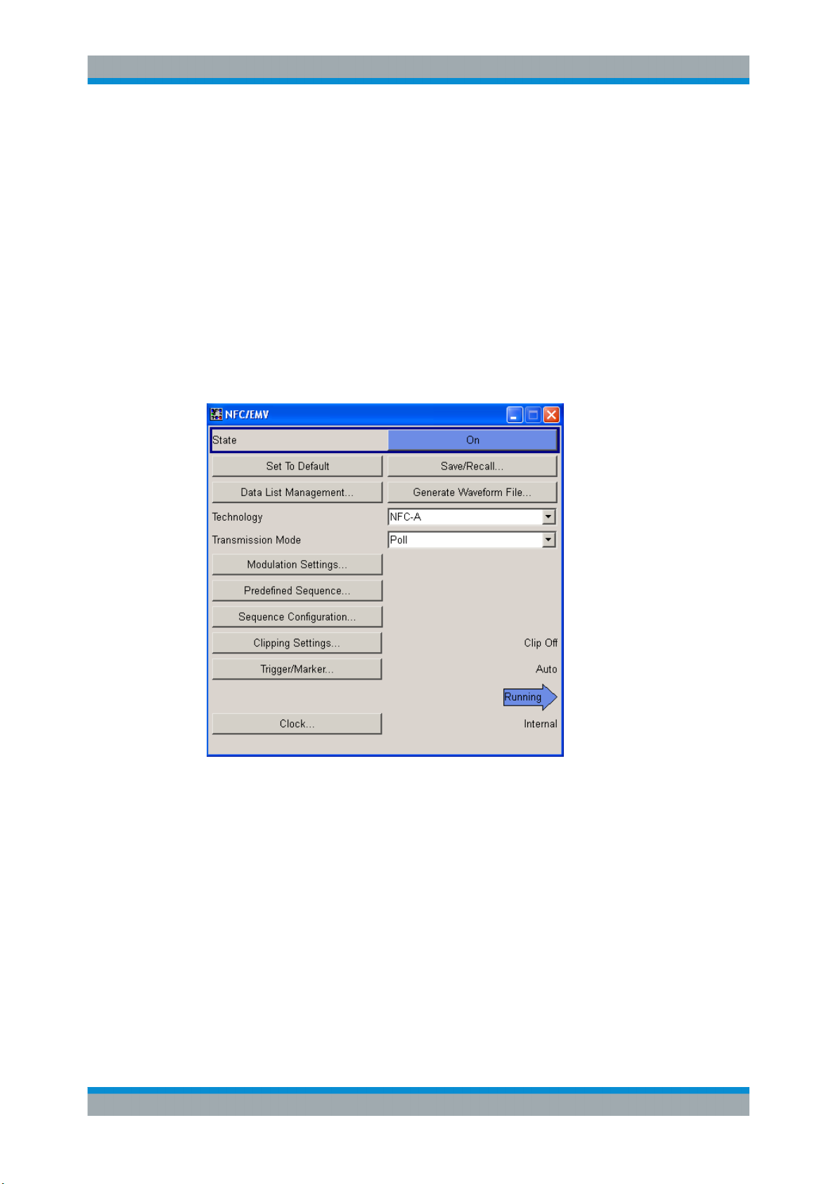
4.1 General Settings
In this dialog, you can enable and reset the digital standard NFC, and configure all the
settings required for the signal in both transmission modes and the different technologies. The provided parameters vary depending on the "Technology", "Transmission
Mode" and "Trigger/Marker...".
Figure 4-1: NFC main dialog
State
Activates the standard and deactivates all the other digital standards and digital modulation modes in the same path.
Remote command:
[:SOURce<hw>]:BB:NFC:STATe on page 72
Set to Default
Calls the default settings. The values of the main parameters are listed in the following
table.
21Operating Manual 1175.7268.02 ─ 10
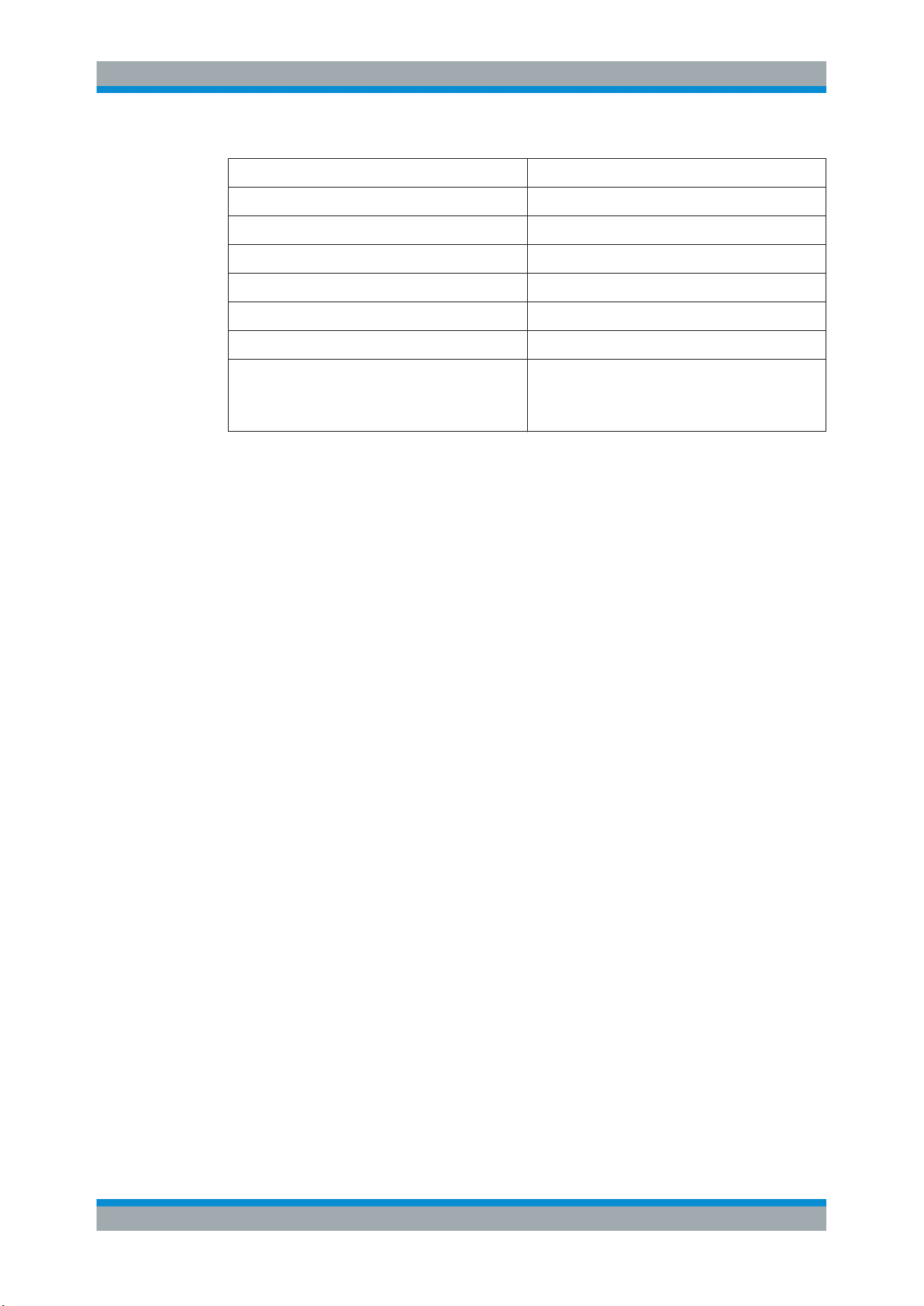
Parameter Value
State Not affected by "Set to default"
Technology NFC A
Transmission Mode Poll
Clipping Off
Trigger Auto
Clock Internal
User InterfaceNFC A/B/F
General Settings
Command Type (in "Sequence Configuration" dialog)
for NFC-A, Poll: SENS_REQ
for NFC-B, Poll: SENSB_REQ
for NFC-F, Poll: SENSF_REQ
Remote command:
[:SOURce<hw>]:BB:NFC:PRESet on page 72
Save/Recall ...
Calls the "Save/Recall" dialog.
From the Save/Recall dialog the "Save/Recall Settings" windows for saving and recalling NFC configurations and the "File Manager" can be called.
NFC configurations are stored as files with the predefined file extension *.nfc. Their
file name and directory are user-definable.
The complete settings in the "NFC" dialog are saved and recalled.
"Recall NFC
Setting"
Opens the "Recall Settings" window for loading a saved NFC configuration.
The configuration of the selected (highlighted) file is loaded by pressing the "Select" button.
"Save NFC
Setting"
Opens the "Save Settings" window for saving the current NFC signal
configuration.
The name of the file is specified in the File name entry field, the directory selected in the save into field. The file is saved by pressing the
"Save" button.
"File Manager"
Calls the "File Manager".
The "File Manager" is used to copy, delete and rename files and to
create new directories.
Remote command:
[:SOURce<hw>]:BB:NFC:SETTing:CATalog? on page 73
[:SOURce<hw>]:BB:NFC:SETTing:LOAD on page 74
[:SOURce<hw>]:BB:NFC:SETTing:STORe on page 74
[:SOURce<hw>]:BB:NFC:SETTing:STORe:FAST on page 74
[:SOURce<hw>]:BB:NFC:SETTing:DELete on page 74
Data List Management...
Calls the "Data List Management" dialog. This dialog is used to create and edit a data
list.
22Operating Manual 1175.7268.02 ─ 10

User InterfaceNFC A/B/F
General Settings
All data lists are stored as files with the predefined file extension *.dm_iqd. Their file
name and directory are user-definable.
The data lists must be selected as a data source from the subsection under the individual function.
Note: All data lists are generated and edited by means of the SOURce:BB:DM subsys-
tem commands. Files containing data lists usually end with *.dm_iqd. The data lists are
selected as a data source for a specific function in the individual subsystems of the digital standard.
Remote command:
[:SOURce<hw>]:BB:NFC:CBLock<ch>:DATA on page 87
[:SOURce<hw>]:BB:NFC:CBLock<ch>:DATA:DSELection on page 87
Generate Waveform File...
With enabled signal generation, triggers the instrument to store the current settings as
an ARB signal in a waveform file. Waveform files can be further processed by the ARB
and/or as a multi-carrier or a multi-segment signal.
The filename and the directory it is stored in are user-definable; the predefined file
extension for waveform files is *.wv.
Remote command:
[:SOURce<hw>]:BB:NFC:WAVeform:CREate on page 73
Technology
Selects the NFC/EMV technology.
"NFC-A, NFC-B, NFC-F"
NFC technology. For details see the NFC Digital Protocol Technical
Specification.
"EMV Type A, EMV Type B"
EMV Technology. For details see the EMV Technical Specification.
Remote command:
[:SOURce<hw>]:BB:NFC:TECHnology on page 72
Divisor(Bit Rate)
Available for "Technology > NFC-F", this parameter selects the used divisor (2 or 4)
and determines the increased resulting bit rate of 212 Kbit/s or 424 Kbit/s respectively.
Remote command:
[:SOURce<hw>]:BB:NFC:DIVisor on page 71
Transmission Mode
Selects the transmission mode.
"Poll / Listen"
"PICC to PCD / PCD to PICC"
Remote command:
[:SOURce<hw>]:BB:NFC:TMODe on page 72
Available for "Technology > NFC-A /NFC-B/ NFC-F"
For details see Figure 2-1.
Available for "Technology > EMV Type A / EMV Type B"
23Operating Manual 1175.7268.02 ─ 10

User InterfaceNFC A/B/F
General Settings
Modulation Settings...
Opens the "Modulation Settings" dialog. See Chapter 4.2, "Modulation Settings",
on page 25
Predefined Sequence
Available for "Transmission Mode > Poll" and "Transmission Mode > PCD to PICC ".
Opens the "Predefined Sequence" dialog. See Chapter 4.3, "Predefined Sequence",
on page 30.
Sequence Configuration...
Opens the "Sequence Configuration" dialog. See Chapter 4.4, "Sequence Configura-
tion Settings", on page 31
Clipping Settings...
Opens the "Clipping Settings" dialog. See Chapter 4.6, "Clipping Settings",
on page 53
Trigger/Marker...
Accesses the "Trigger/Marker/Clock" dialog, see Chapter 4.7, "Trigger/Marker/Clock
Settings", on page 53.
Execute Trigger
Executes trigger manually.
You can execute the trigger manually only if you select an internal trigger source and a
trigger mode other than "Auto".
Remote command:
[:SOURce<hw>]:BB:NFC:TRIGger:EXECute on page 108
Clock...
Accesses the "Trigger/Marker/Clock" dialog. See Chapter 4.7, "Trigger/Marker/Clock
Settings", on page 53
Unmodulated Parts Voltage To Peak Voltage Ratio
Available only for "Transmission Mode > Listen / PICC to PCD" and "State > On".
Displays the ratio of the voltage in the unmodulated parts of the signal to its peak
value. See Chapter 2.3, "Leveling aspects", on page 16.
Remote command:
[:SOURce<hw>]:BB:NFC:UPVoltage? on page 73
Desired Voltage In Unmodulated Signal parts
Available only for "Transmission Mode > Listen / PICC to PCD" and "State > On".
Defines the desired voltage in unmodulated signal parts.
The displayed "Unmodulated ... Ratio" depends only on the signal and is not changed
by the input of a "Desired Voltage".
See Chapter 2.3, "Leveling aspects", on page 16.
Remote command:
[:SOURce<hw>]:BB:NFC:DVOLtage on page 71
24Operating Manual 1175.7268.02 ─ 10
User InterfaceNFC A/B/F
Modulation Settings
Update Analog I/Q Settings For Desired Voltage
Available only for "Transmission Mode > Listen / PICC to PCD" and "State > On".
Automatically adjusts the related parameters of the analog I and Q outputs to the
desired voltage.
For detailed description of all parameters, refer to section "Output of the Baseband Signal" in the operating manual of the signal generator.
See Chapter 2.3, "Leveling aspects", on page 16.
Remote command:
[:SOURce<hw>]:BB:NFC:UAISetting on page 72
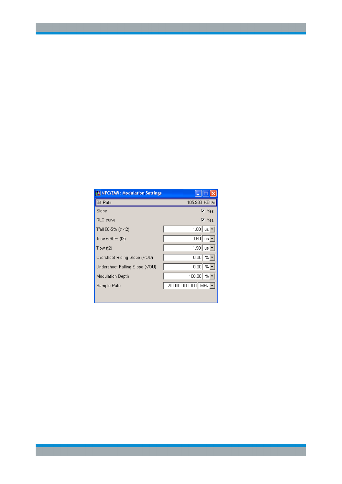
4.2 Modulation Settings
► To access the modulation settings, select "Main Dialog > Modulation Settings".
This dialog contains the parameters for configuring the signal modulation. The
available Various parameters vary depending on the selected technology and
transmission mode, and if "Slope" or "RLC curve" is activated.
The current resulting bit rate is indicated.
Bit Rate
Indicates the current resulting bit rate in Kbit/s.
Remote command:
[:SOURce<hw>]:BB:NFC:MSET:BRATe? on page 104
Slope
Determines the transition between the modulated and unmodulated parts.
25Operating Manual 1175.7268.02 ─ 10

Figure 4-2: Impact of the "Slope" parameter ("RLC Curve" = Off)
User InterfaceNFC A/B/F
Modulation Settings
"Off"
A bursted signal with pulse like shape is generated. The transition
time from high to low or low to high is only one sample.
"On"
A longer transition time is used.
Remote command:
[:SOURce<hw>]:BB:NFC:MSET:SLOPe on page 104
RLC curve
Determines if an RLC curve (= discharge/charge curve of an RLC-circuit) is applied to
the signal.
Figure 4-3: Impact of the "RLC Curve" parameter ("RLC Curve" = On)
"On"
"Off"
An "RLC curve" is applied to the signal
A linear ramp is used.
Remote command:
[:SOURce<hw>]:BB:NFC:MSET:RCURve on page 105
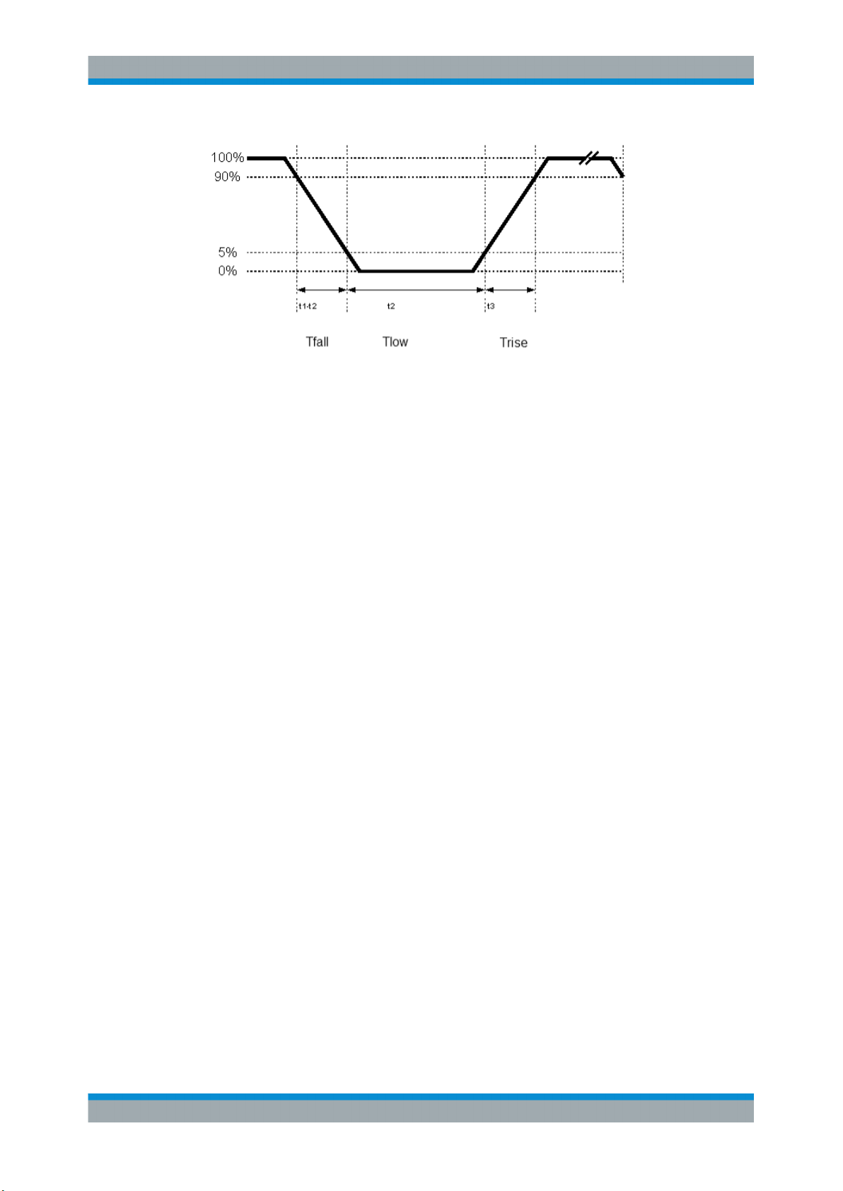
Tfall 90-10 % / 90-5 % (t1-t2)
Defines the signals fall time (90 to 5 % or 90 to 10%) in µs.
26Operating Manual 1175.7268.02 ─ 10
User InterfaceNFC A/B/F
Modulation Settings
Figure 4-4: Definition of Tfall, Trise, Tlow at an NFC-A Polling Device to Listening Device
Remote command:
[:SOURce<hw>]:BB:NFC:MSET:TFALl on page 106
Trise 10-90 % / 5-90% (t3)
Defines the signals rise time (5 to 90 % or 10 to 90 %) in µs, see also "Tfall 90-10 % /
90-5 % (t1-t2)" on page 26.
Remote command:
[:SOURce<hw>]:BB:NFC:MSET:TRISe on page 106
Tlow (t2)
Available only for NFC-A in "Transmission Mode > Poll" and EMV A in "Transmission
Mode > PCD to PICC".
Defines the signals low time (below 5%) in µs.
Remote command:
[:SOURce<hw>]:BB:NFC:MSET:TLOW on page 106
Overshoot Rising Slope (VOU)
Determines the size of the overshoot after the rising slope. The parameter corresponds
to the value VOU in the NFC Analog Technical Specification. Overshoot Rising Slope is
in percent of the difference between the nominal high voltage to the nominal low voltage, according to the following formula:
Overshoot in Volts = VOU x (Va - Vb),
where Va is the nominal high voltage and Vb is the nominal low voltage.
Remote command:
[:SOURce<hw>]:BB:NFC:MSET:OSRise on page 105
Undershoot Falling Slope (VOU)
Determines the size of the undershoot (ringing) after the falling slope. The parameter
corresponds to the value VOU in the NFC Analog Technical Specification. Undershoot
Falling Slope is in percent of the difference between the nominal high voltage to the
nominal low voltage, according to the following formula:
Undershoot in Volts = VOU x (Va - Vb),
27Operating Manual 1175.7268.02 ─ 10

User InterfaceNFC A/B/F
ba
ba
i
VV
VV
m
Modulation Settings
where Va is the nominal high voltage and Vb is the nominal low voltage.
Remote command:
[:SOURce<hw>]:BB:NFC:MSET:USFall on page 107
Modulation Depth
Available only for NFC-A in "Transmission Mode > Poll" and EMV A in "Transmission
Mode > PCD to PICC".
Sets the ASK modulation depth. The modulation depth indicates the magnitude of the
voltage drop during the low state transition. The modulation depth is a percentage relative to the voltage of the carrier signal (V1).
Remote command:
[:SOURce<hw>]:BB:NFC:MSET:MDEPth on page 105
Modulation index
Defines the signal's modulation index in %.
The modulation index represents the power drop during the low state transitions as a
ratio of voltages at defined locations of the low state transition.
where Va is the nominal high voltage and Vb is the nominal low voltage.
Remote command:
[:SOURce<hw>]:BB:NFC:MSET:MINDex on page 105
Inverse Modulation
When selected, inverse modulation will be used.
Remote command:
[:SOURce<hw>]:BB:NFC:MSET:IMODulation on page 104
Baseband Output
Available only for all "Listen" and "PICC to PCD" modes.
The default state is "On". When activated the signal at the baseband output changes
between 0% and 100% voltage to be able to control the Reference Listeners. When
deactivated baseband output delivers the envelope of the RF signal.
28Operating Manual 1175.7268.02 ─ 10

User InterfaceNFC A/B/F
Modulation Settings
Figure 4-5: Impact of the parameter "Baseband Output"
Remote command:
[:SOURce<hw>]:BB:NFC:MSET:BOUTput on page 104
Sample Rate
In contrast to mobile radio standards (where this parameter is the "Sample Rate Variation"), the NFC standard does not prescribe a sample- or chiprate, but defines requirements e.g. for edge steepness.
At mobile radio standards, a change of the "Sample Rate Variation" does not change
the number of samples per slot/frame/superframe etc., but rather plays the signal
"faster" or "slower".
At NFC, the "Sample Rate" parameter changes the time resolution of signal generation, e.g. of how many samples an NFC-A bit duration is formed.
The 20 MSamples/s default value is a good trade-off between signal quality and
required calculation time.
Remote command:
[:SOURce<hw>]:BB:NFC:MSET:SRATe on page 106
29Operating Manual 1175.7268.02 ─ 10
User InterfaceNFC A/B/F
Predefined Sequence
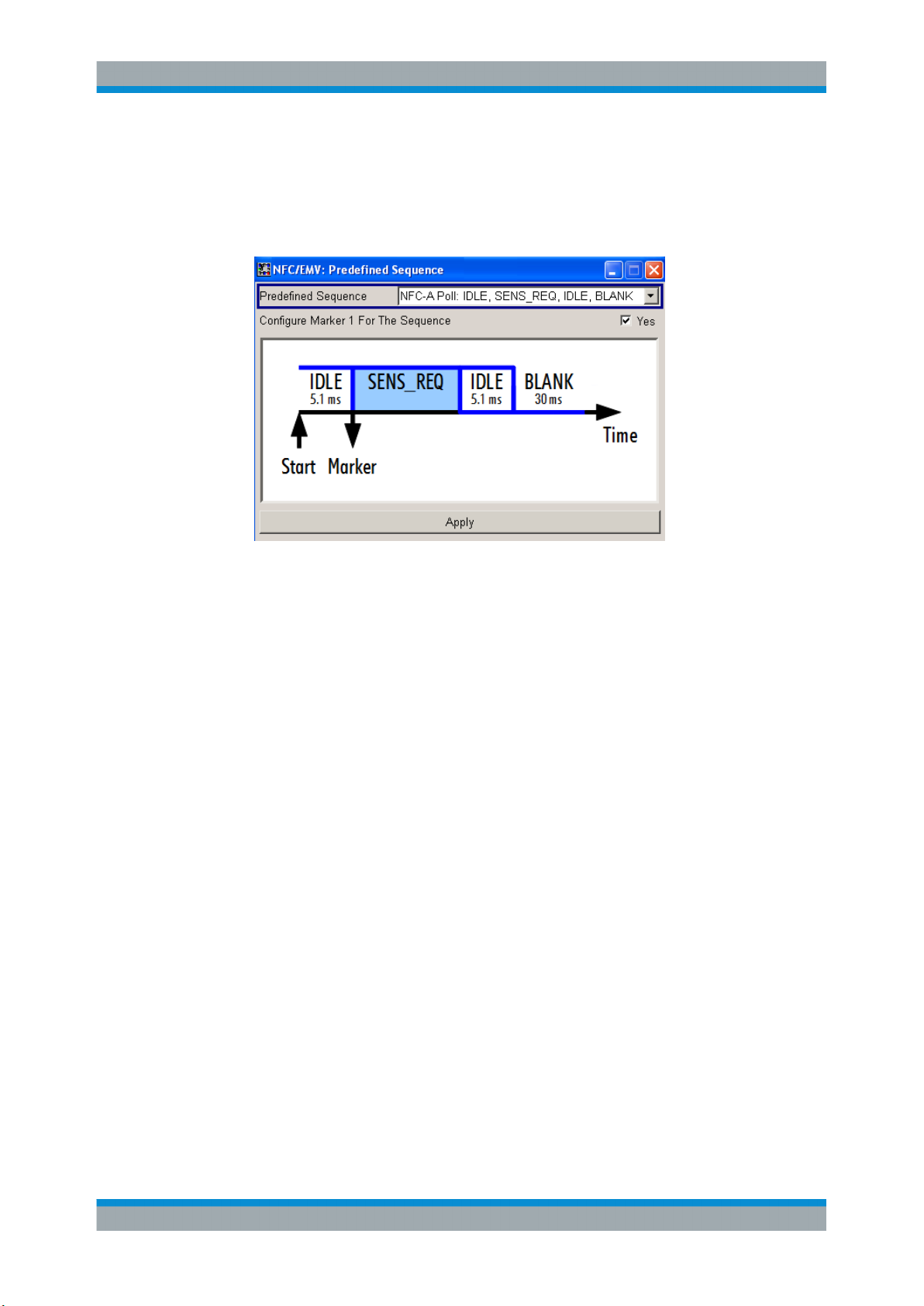
4.3 Predefined Sequence
► To access this dialog select "Main Dialog > Predefined Sequence"
Figure 4-6: Predefined Sequence dialog. The marker is available for signal generators only.
This dialog contains the parameters to define a predefined sequence for transmission modes "Poll" and "PCD to PICC".
Predefined Sequence
Selects a predefined sequence.
Remote command:
[:SOURce<hw>]:BB:NFC:PRED:SEQuence on page 75
Configure Marker 1 For The Sequence
Note: Available for signal generators only.
Enables Marker 1 as shown in the picture of the dialog.
Remote command:
[:SOURce<hw>]:BB:NFC:PRED:CNFMarker on page 75
Apply
Activates the selected "Predefined Sequence" and marker status.
Remote command:
[:SOURce<hw>]:BB:NFC:PRED:APPLy on page 76
30Operating Manual 1175.7268.02 ─ 10
 Loading...