


R&S®SMBV-K131
LoRa
User Manual
(;ÝBM2)
1179182902
User Manual
Version 01

This document describes the following software option:
●
R&S®SMBV-K131
1419.1783.02
This manual describes firmware version 4.70.108.xx and later of the R&S®SMBV100A.
© 2020 Rohde & Schwarz GmbH & Co. KG
Mühldorfstr. 15, 81671 München, Germany
Phone: +49 89 41 29 - 0
Fax: +49 89 41 29 12 164
Email: info@rohde-schwarz.com
Internet: www.rohde-schwarz.com
Subject to change – Data without tolerance limits is not binding.
R&S® is a registered trademark of Rohde & Schwarz GmbH & Co. KG.
LoRa® Mark and LoRa Logo are registered trademarks of Semtech Corporation.
LoRaWAN® Mark and LoRaWAN Logo are registered trademarks of LoRa Alliance, Inc..
Trade names are trademarks of the owners.
1179.1829.02 | Version 01 | R&S®SMBV-K131
The following abbreviations are used throughout this manual: R&S®SMBV100 is abbreviated as R&S SMBV.

R&S®SMBV-K131
1 Preface.................................................................................................... 5
1.1 About this Manual......................................................................................................... 5
1.2 Documentation Overview............................................................................................. 6
1.2.1 Quick Start Guide Manual............................................................................................... 6
1.2.2 Operating Manual and Help............................................................................................ 6
1.2.3 Service Manual............................................................................................................... 6
1.2.4 Instrument Security Procedures......................................................................................7
1.2.5 Basic Safety Instructions.................................................................................................7
1.2.6 Data Sheets and Brochures............................................................................................ 7
1.2.7 Release Notes and Open Source Acknowledgment (OSA)............................................ 7
1.2.8 Application Notes, Application Cards, White Papers, etc................................................7
Contents
Contents
2 Welcome to the LoRa Option................................................................ 8
2.1 Accessing the LoRa Dialog..........................................................................................8
2.2 Scope............................................................................................................................. 9
2.3 Notes on Screenshots.................................................................................................. 9
3 About the LoRa Option........................................................................10
3.1 Required Options........................................................................................................ 10
3.2 About LoRa..................................................................................................................10
3.3 About LoRaWAN......................................................................................................... 12
4 LoRa Configuration and Settings....................................................... 15
4.1 General Settings..........................................................................................................15
4.2 Frame Configuration Settings....................................................................................18
4.3 Impairments Settings..................................................................................................22
5 Trigger/Marker/Clock Settings............................................................24
5.1 Trigger In......................................................................................................................24
5.2 Marker Mode................................................................................................................ 28
5.3 Marker Delay................................................................................................................29
5.4 Clock Settings............................................................................................................. 30
5.5 Global Settings............................................................................................................32
6 Remote-Control Commands............................................................... 33
3User Manual 1179.1829.02 ─ 01

R&S®SMBV-K131
6.1 Programming Examples............................................................................................. 34
6.2 General Commands.................................................................................................... 37
6.3 Frame Configuration Commands.............................................................................. 41
6.4 Impairments Commands............................................................................................ 45
6.5 Trigger Commands..................................................................................................... 47
6.6 Marker Commands......................................................................................................50
6.7 Clock Commands........................................................................................................54
Contents
Glossary: Abbreviations and Definitions...........................................56
Glossary: Specifications and References......................................... 57
List of Commands................................................................................58
Index......................................................................................................60
4User Manual 1179.1829.02 ─ 01

R&S®SMBV-K131
1 Preface
1.1 About this Manual
Preface
About this Manual
This operating manual provides all the information specific to the LoRa option
R&S SMBV-K131. All general instrument functions and settings common to all applications and operating modes are described in the main R&S SMBV operating manual.
The main focus in this manual is on the provided settings and the tasks required to
generate a signal. The following topics are included:
●
Welcome to the LoRa option R&S SMBV-K131
Introduction to and getting familiar with the option
●
About the LoRa
Background information on basic terms and principles in the context of the signal
generation
●
LoRa Configuration and Settings
A concise description of all functions and settings available to configure signal generation with their corresponding remote control command
●
Remote Control Commands
Remote commands required to configure and perform signal generation in a
remote environment, sorted by tasks
(Commands required to set up the instrument or to perform common tasks on the
instrument are provided in the main R&S SMBV operating manual)
Programming examples demonstrate the use of many commands and can usually
be executed directly for test purposes
●
Glossary
Alphabetical list of reference material such as application notes and specifications
●
List of remote commands
Alphabetical list of all remote commands described in the manual
●
Index
The functions specific to the discontinued products R&S®SMU200A,
R&S®SMATE200A, R&S®SMJ100A and R&S®AMU200A are not described here.
Find the description of the corresponding option at the following page:
https://www.rohde-schwarz.com/product/SMU200A > "Downloads"
Contents and scope
This description assumes R&S SMBV equipped with all available options. Depending
on your model and the installed options, some of the functions may not be available on
your instrument.
Notes on screenshots
When describing the functions of the product, we use sample screenshots. These
screenshots are meant to illustrate as much as possible of the provided functions and
5User Manual 1179.1829.02 ─ 01

R&S®SMBV-K131
1.2 Documentation Overview
1.2.1 Quick Start Guide Manual
Preface
Documentation Overview
possible interdependencies between parameters. The shown values may not represent
realistic usage scenarios.
The screenshots usually show a fully equipped product, that is: with all options installed. Thus, some functions shown in the screenshots may not be available in your particular product configuration.
This section provides an overview of the R&S SMBV user documentation. Unless
specified otherwise, you find the documents on the R&S SMBV product page at:
www.rohde-schwarz.com/manual/smbv100a
Introduces the R&S SMBV and describes how to set up and start working with the
product. Includes basic operations, typical measurement examples, and general information, e.g. safety instructions, etc. A printed version is delivered with the instrument.
1.2.2 Operating Manual and Help
Separate manuals for the base unit and the software options are provided for download:
●
Base unit manual
Contains the description of all instrument modes and functions. It also provides an
introduction to remote control, a complete description of the remote control commands with programming examples, and information on maintenance, instrument
interfaces and error messages. Includes the contents of the quick start guide manual.
●
Software option manual
Contains the description of the specific functions of an option. Basic information on
operating the R&S SMBV is not included.
The contents of the user manuals are available as help in the R&S SMBV. The help
offers quick, context-sensitive access to the complete information for the base unit and
the software options.
All user manuals are also available for download or for immediate display on the Internet.
1.2.3 Service Manual
Describes the performance test for checking the rated specifications, module replacement and repair, firmware update, troubleshooting and fault elimination, and contains
mechanical drawings and spare part lists.
6User Manual 1179.1829.02 ─ 01

R&S®SMBV-K131
1.2.4 Instrument Security Procedures
1.2.5 Basic Safety Instructions
1.2.6 Data Sheets and Brochures
Preface
Documentation Overview
The service manual is available for registered users on the global Rohde & Schwarz
information system (GLORIS, https://gloris.rohde-schwarz.com).
Deals with security issues when working with the R&S SMBV in secure areas. It is
available for download on the Internet.
Contains safety instructions, operating conditions and further important information.
The printed document is delivered with the instrument.
The data sheet contains the technical specifications of the R&S SMBV. It also lists the
options and their order numbers and optional accessories.
The brochure provides an overview of the instrument and deals with the specific characteristics.
See www.rohde-schwarz.com/brochure-datasheet/smbv100a
1.2.7 Release Notes and Open Source Acknowledgment (OSA)
The release notes list new features, improvements and known issues of the current
firmware version, and describe the firmware installation.
The open source acknowledgment document provides verbatim license texts of the
used open source software.
See www.rohde-schwarz.com/firmware/smbv100a
1.2.8 Application Notes, Application Cards, White Papers, etc.
These documents deal with special applications or background information on particular topics.
See www.rohde-schwarz.com/application/smbv100a.
7User Manual 1179.1829.02 ─ 01

R&S®SMBV-K131
2 Welcome to the LoRa Option
Welcome to the LoRa Option
Accessing the LoRa Dialog
The R&S SMBV-K131 is a firmware application that adds functionality to generate signals in accordance with LoRa modulation.
The R&S SMBV-K131 features
●
Generation of waveforms for LoRa up-/downlink signals
●
Frame configuration including modulation, coding and data configuration
●
Impairing the output signal:
– Adding symbol timing error and frequency offset
– Applying a frequency drift to the carrier frequency of the output signal
This operating manual contains a description of the functionality that the application
provides, including remote control operation.
All functions not discussed in this manual are the same as in the base unit and are
described in the R&S SMBV operating manual. The latest version is available at:
www.rohde-schwarz.com/manual/SMBV100A
2.1 Accessing the LoRa Dialog
To open the dialog with LoRa settings
► In the block diagram of the R&S SMBV, select "Baseband > LoRa".
A dialog box opens that displays the provided general settings.
The signal generation is not started immediately. To start signal generation with the
default settings, select "State > On".
8User Manual 1179.1829.02 ─ 01
R&S®SMBV-K131
2.2 Scope
Welcome to the LoRa Option
Notes on Screenshots
Tasks (in manual or remote operation) that are also performed in the base unit in the
same way are not described here.
In particular, it includes:
●
Managing settings and data lists, like storing and loading settings, creating and
accessing data lists, or accessing files in a particular directory.
●
Information on regular trigger, marker and clock signals and filter settings, if appropriate.
●
General instrument configuration, such as configuring networks and remote operation
●
Using the common status registers
For a description of such tasks, see the R&S SMBV operating manual.
2.3 Notes on Screenshots
When describing the functions of the product, we use sample screenshots. These
screenshots are meant to illustrate as many as possible of the provided functions and
possible interdependencies between parameters. The shown values may not represent
realistic usage scenarios.
The screenshots usually show a fully equipped product, that is: with all options installed. Thus, some functions shown in the screenshots may not be available in your particular product configuration.
9User Manual 1179.1829.02 ─ 01

R&S®SMBV-K131
3 About the LoRa Option
3.1 Required Options
3.2 About LoRa
About the LoRa Option
About LoRa
To play back a signal from a waveform file created by the simulation software
R&S WinIQSIM2, the corresponding R&S WinIQSIM2 digital standard option must be
installed.
For more information, see data sheet.
The term LoRa refers to a "Long Range" end-to-end communication technology based
on a PHY with a proprietary modulation scheme. The standard is owned by Semtech
Corporation, Camarillo California, USA.
Modulation
LoRa modulation is based on a proprietary CSS modulation scheme. The modulation
scheme is used to encode data onto swept frequency chirps, i.e. rapid changes of the
modulation frequency.
A chirp (compressed high intensity radar pulse) is a signal whose frequency changes
at a fixed rate (chirp rate). Each modulation symbol is represented as a rapid change in
the frequency of the chirp.
The spreading factor represents the number of encoded bits per symbol and thus the
change in frequency per unit time.
The higher the spreading factor, the lower the change in frequency per unit time.
10User Manual 1179.1829.02 ─ 01

R&S®SMBV-K131
About the LoRa Option
About LoRa
Chirp rate RC, signal bandwidth Δf, spreading factor SF, sample rate RS, symbol duration TS, bit rate RB and coding rate CR are linked as in the equations below. Further
more, typical values are given for SF, Δf and CR.
Symbol rate: RS = 1 / TS = Δf / 2SF 125 kHz ≤ Δf ≤ 500 kHz;
Chirp rate: RC = RS * 2SF = Δf 7 ≤ SF ≤ 12;
Bit rate: RB = SF * Δf / 2SF * 4 / (4 + CR) 1 ≤ CR ≤ 4
A coding rate CR = 0 corresponds to no coding.
For related settings, see "Modulation and Coding Configuration" on page 20.
Channel allocation
LoRa communication channels can be freely attributed by the network following the
spectrum allocation rules defined by the regional radio regulation authorities. In
Europe, the allocation rules are defined by ETSI in the specifications ETSI Specifica-
tion EN 300 220-1 and CEPT/ERC Recommendation 70-03. In North America, the allo-
cation rules are defined by FCC in the FCC Specification 47 Part 15.247.
For detailed info about regional LoRa performance requirements, see LoRaWAN
Regional Parameters Specification.
Table 3-1: Example: LoRaWAN regional parameters for Europe and North America
Parameter Europe (ETSI) North America (FCC)
Frequency band 863 MHz to 869 MHz 902 MHz to 928 MHz
Number of channels Up- and downlink: 10 Uplink: 64 x 125 kHz and 8 x 500 kHz
Downlink: 8 x 500 kHz
Channel bandwidth Uplink: 125 kHz and 250 kHz
Downlink 125 kHz
TX power Uplink: 14 dBm (20 dBm allowed)
Downlink: 14 dBm
Uplink: 125 kHz and 500 kHz
Downlink: 500 kHz
Uplink: 20 dBm (30 dBm allowed)
Downlink: 27 dBm
Spreading factor Uplink: 7 to 12 Uplink: 7 to 12
Data rate 250 bit/s to 50000 bit/s 980 bit/s to 21900 bit/s
Link budget Uplink: 155 dB
Downlink: 155 dB
Uplink: 154 dB
Downlink: 157 dB
For related settings, see Chapter 4.1, "General Settings", on page 15.
11User Manual 1179.1829.02 ─ 01
R&S®SMBV-K131
About the LoRa Option
About LoRaWAN
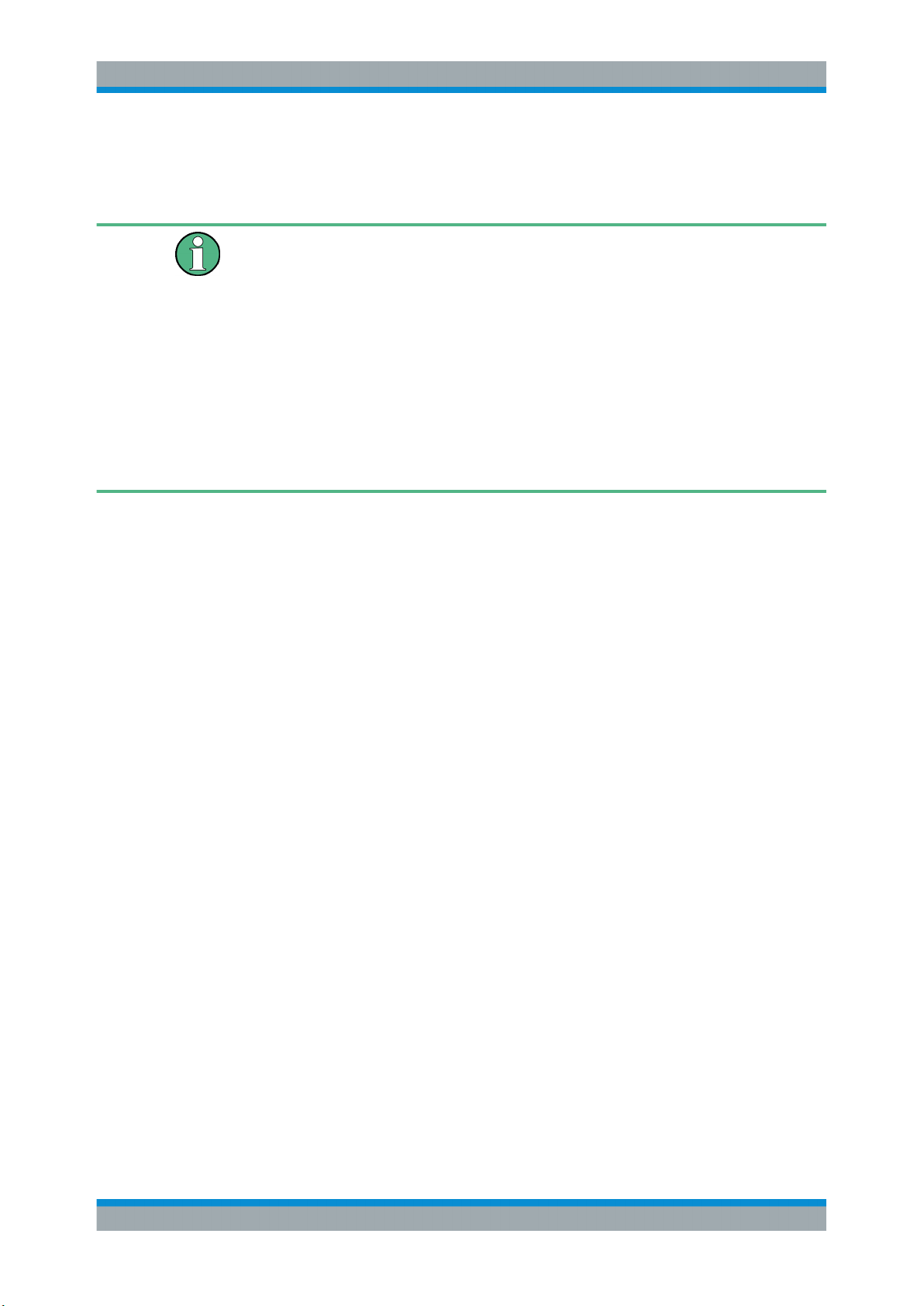
Message and frame structure
For related settings, see Chapter 4.2, "Frame Configuration Settings", on page 18.
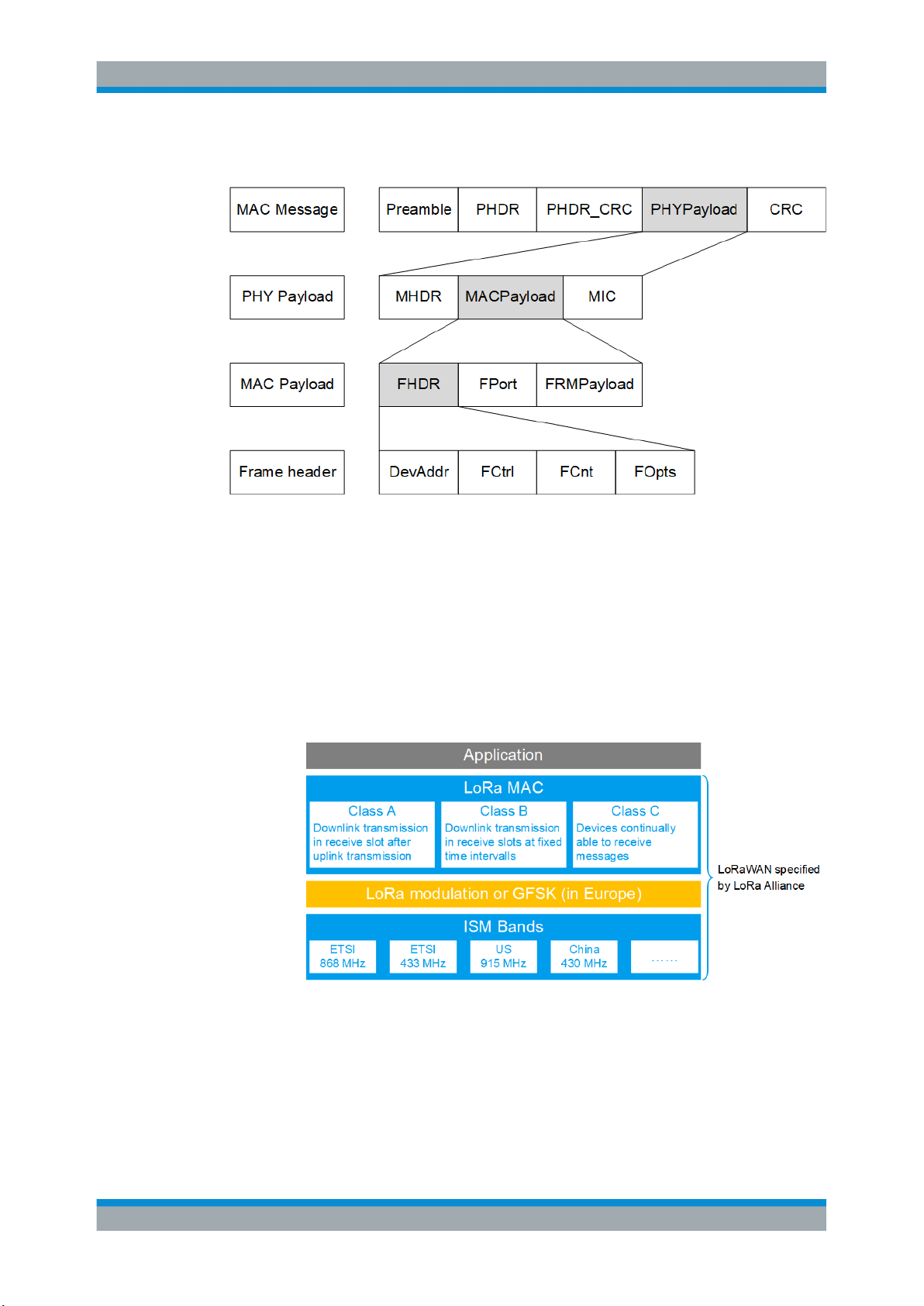
3.3 About LoRaWAN
The LoRa Alliance, Inc. specifies a wide area network (WAN) stack for long range communication as shown in Figure 3-1 (1MA295). The LoRa modulation physical layer
enables the long-range communication link. The LoRa MAC and application layers
affect battery lifetime of the end-device, network capacity, quality of service and security.
Figure 3-1: LoRaWAN stack
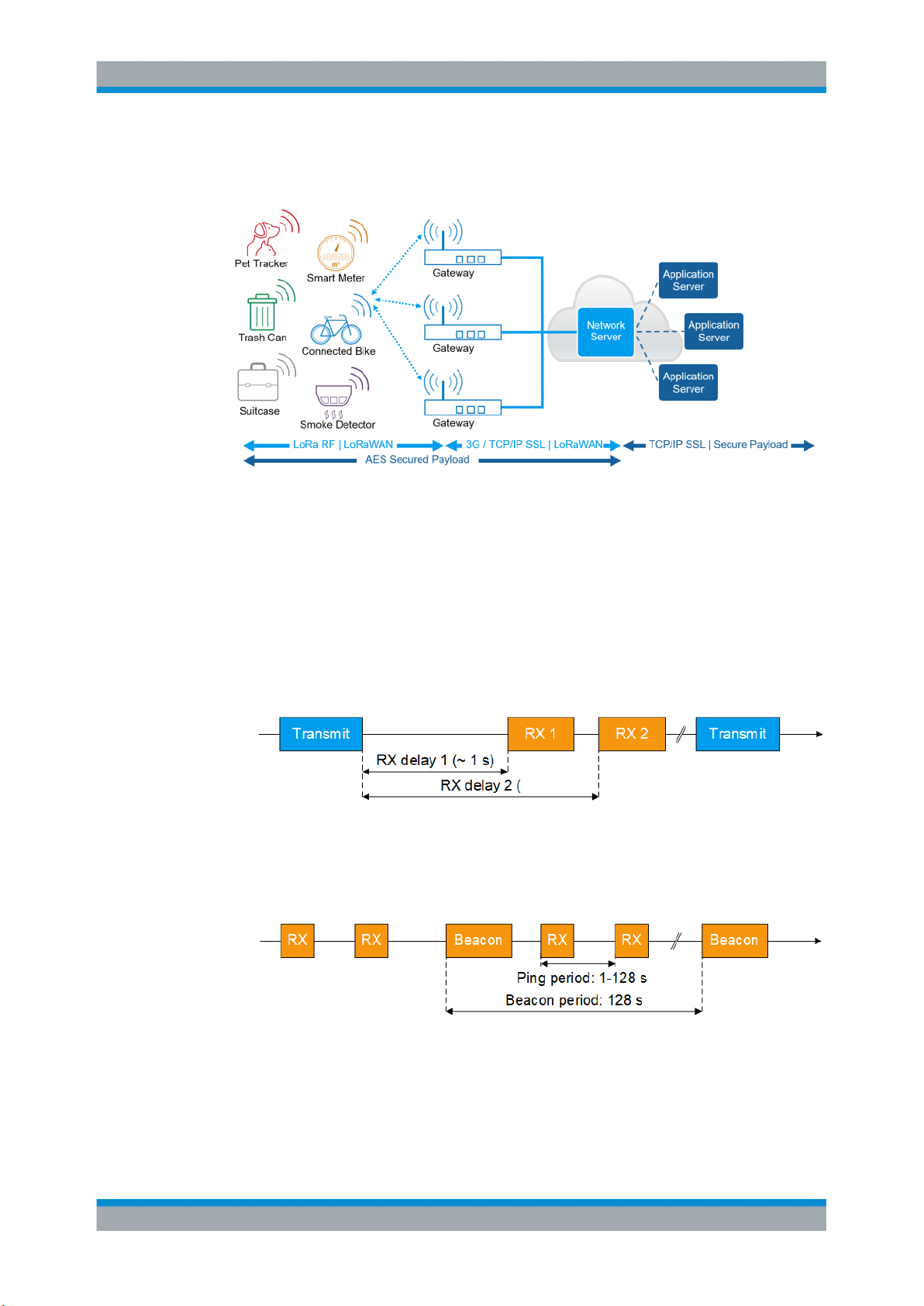
Network architecture
A LoRaWAN architecture has a star-shaped structure as shown in Figure 3-2
(1MA295). End-devices exchange data with the network server via gateways. Also, the
12User Manual 1179.1829.02 ─ 01
R&S®SMBV-K131
About the LoRa Option
About LoRaWAN
network server is connected to application servers, on which typically IoT applications
run.
Figure 3-2: LoRaWAN network architecture
For more information, see the LoRaWAN Specification.
Device communication classes
There are three classes specified for LoRaWAN compliant devices:
●
Class A: Bi-directional end-devices (mandatory support)
Bi-directional communication between LoRa network server and receiver. A scheduled uplink transmission slot (Transmit) is followed by two downlink receive slots
(Rx 1 and Rx 2).
Figure 3-3: Class A communication
●
Class B: Bi-directional end-devices with scheduled receive slots (optional support)
Besides Class A communication, more downlink receive slots (Rx) are available
due to a time synchronized periodic beacon signal (Beacon) from network gateway.
Figure 3-4: Class B communication
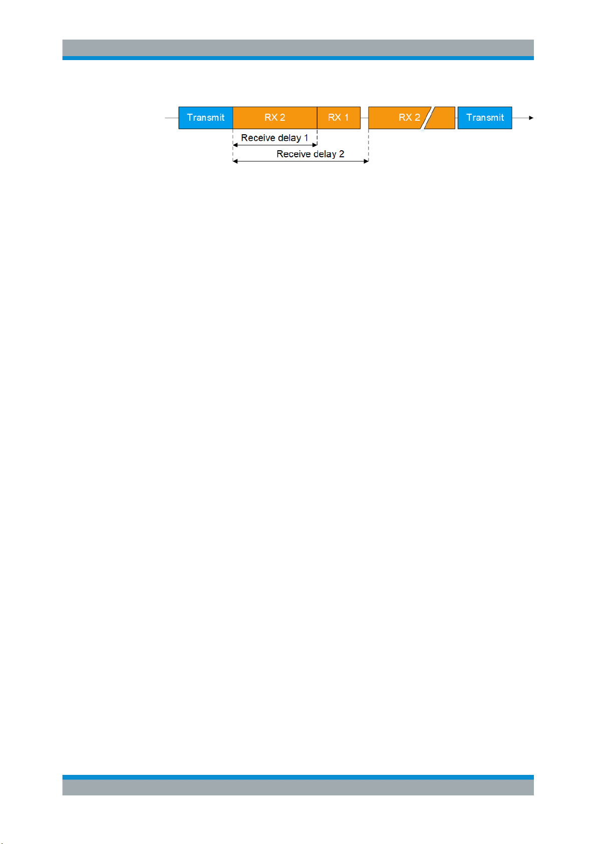
●
Class C: Bi-directional end-devices with maximal receive slots (optional support)
Besides Class A and B communication, there are continuously open receive slots
except during transmission.
13User Manual 1179.1829.02 ─ 01
R&S®SMBV-K131
About the LoRa Option
About LoRaWAN
Figure 3-5: Class C communication
Typically, power consumption increases and latency decreases from Class A to Class
C communication.
Key features and applications
Devices compliant with the LoRa technology and operating in a LoRaWAN offer the following key features:
●
Long range: outdoor coverage of up to 30 miles/48.3 km (line of sight)
●
Low power consumption: battery lifetime of up to 20 years
●
Low cost: low-cost end-devices and open software
The key features meet the requirements for IoT applications in rural areas.
14User Manual 1179.1829.02 ─ 01

R&S®SMBV-K131
4 LoRa Configuration and Settings
4.1 General Settings
LoRa Configuration and Settings
General Settings
Access:
► Select "Baseband > LoRa".
The remote commands required to define these settings are described in Chapter 6,
"Remote-Control Commands", on page 33.
Settings:
● General Settings..................................................................................................... 15
● Frame Configuration Settings................................................................................. 18
● Impairments Settings.............................................................................................. 22
Access:
► Select "Baseband > LoRa".
This tab comprises the standard general settings.
15User Manual 1179.1829.02 ─ 01

R&S®SMBV-K131
LoRa Configuration and Settings
General Settings
Settings:
State..............................................................................................................................16
Set to Default................................................................................................................ 16
Save/Recall...................................................................................................................16
Data List Management..................................................................................................17
Generate Waveform File...............................................................................................17
Bandwidth..................................................................................................................... 17
Idle Interval....................................................................................................................17
Sequence Length..........................................................................................................18
Oversampling................................................................................................................18
Sample Rate Variation...................................................................................................18
Frame Configuration..................................................................................................... 18
Impairments.................................................................................................................. 18
State
Activates the standard and deactivates all the other digital standards and digital modulation modes in the same path.
Remote command:
[:SOURce<hw>]:BB:LORA:STATe on page 40
Set to Default
Calls the default settings. The values of the main parameters are listed in the following
table.
Parameter Value
"State" Not affected by the "Set to Default"
"Bandwidth" 125 kHz
"Idle Interval" 100.0 us
"Sequence Length" 1 frame
"Oversampling" 4
"Sample Rate Variation" 500.000 000 kHz
Remote command:
[:SOURce<hw>]:BB:LORA:PRESet on page 38
Save/Recall
Accesses the "Save/Recall" dialog, that is the standard instrument function for saving
and recalling the complete dialog-related settings in a file. The provided navigation
possibilities in the dialog are self-explanatory.
The filename and the directory, in that the settings are stored, are user-definable; the
file extension is however predefined.
Remote command:
[:SOURce<hw>]:BB:LORA:SETTing:CATalog on page 38
[:SOURce<hw>]:BB:LORA:SETTing:STORe on page 39
[:SOURce<hw>]:BB:LORA:SETTing:STORe:FAST on page 39
16User Manual 1179.1829.02 ─ 01
R&S®SMBV-K131
LoRa Configuration and Settings
General Settings
[:SOURce<hw>]:BB:LORA:SETTing:LOAD on page 39
[:SOURce<hw>]:BB:LORA:SETTing:DELete on page 38
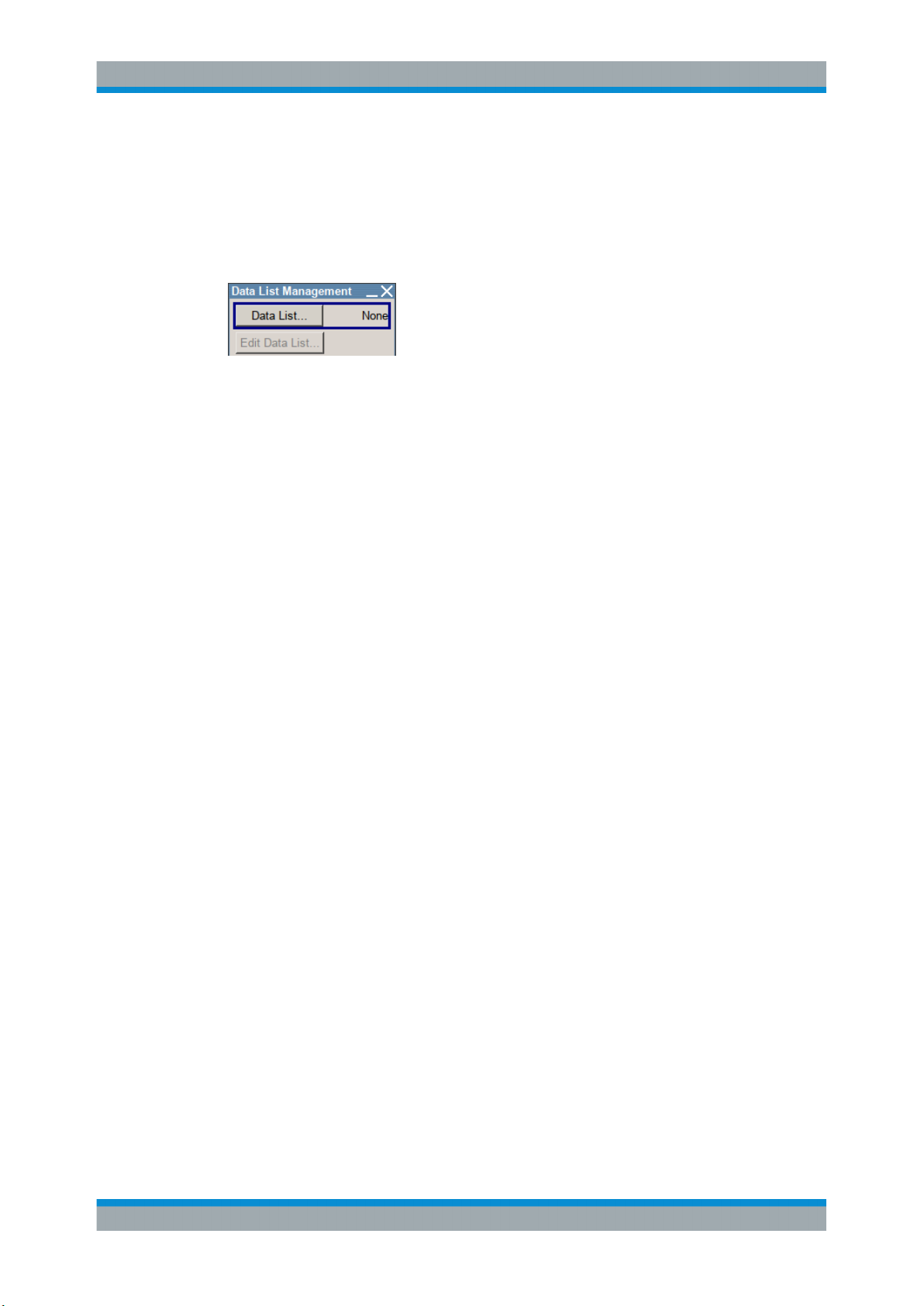
Data List Management
Accesses the "Data List Management" dialog. This menu is used to create and edit a
data list.
All data lists are stored as files with the predefined file extension *.dm_iqd. The file
name and the directory they are user-definable.
The data lists must be selected as a data source from the submenus under the individual function, e.g. in the channel table of the cells.
Note: All data lists are generated and edited by the SOURce:BB:DM subsystem com-
mands. Files containing data lists usually end with *.dm_iqd. The data lists are
selected as a data source for a specific function in the individual subsystems of the digital standard.
Example: Creating and editing the data list
SOUR:BB:DM:DLIS:SEL 'd_list1'
SOUR:BB:DM:DLIS:DATA #B1111010101000001111....
SOUR:BB:DM:DLIS:DATA:APP #B1111010101000001111....
Remote command:
[:SOURce<hw>]:BB:LORA:FCONfiguration:DATA on page 42
[:SOURce<hw>]:BB:LORA:FCONfiguration:DATA:DSELection on page 42
Generate Waveform File
With enabled signal generation, triggers the instrument to store the current settings as
an ARB signal in a waveform file. Waveform files can be further processed by the ARB
and/or as a multi-carrier or a multi-segment signal.
The filename and the directory it is stored in are user-definable; the predefined file
extension for waveform files is *.wv.
Remote command:
[:SOURce<hw>]:BB:LORA:WAVeform:CREate on page 41
Bandwidth
Sets the channel bandwidth.
The sample rate and FFT size are calculated internally and updated automatically.
Remote command:
[:SOURce<hw>]:BB:LORA:BWIDth on page 37
Idle Interval
Sets the time of the interval separating two frames.
17User Manual 1179.1829.02 ─ 01

R&S®SMBV-K131
LoRa Configuration and Settings
Frame Configuration Settings
Remote command:
[:SOURce<hw>]:BB:LORA:IINTerval on page 38
Sequence Length
Sets the sequence length of the signal in number of frames. The signal is calculated in
advance and output in the arbitrary waveform generator.
Remote command:
[:SOURce<hw>]:BB:LORA:SLENgth on page 39
Oversampling
Sets the oversampling factor of the generated waveform. The ARB generator of the
R&S SMBV requires low oversampling factors and still provides excellent signal quality
in terms of EVM and ACP.
A reduced sample rate saves significantly the amount of memory or allows an
increased signal cycle time, and vice versa.
Remote command:
[:SOURce<hw>]:BB:LORA:OSAMpling on page 40
Sample Rate Variation
Sets the sample rate of the signal. A variation of this parameter affects the ARB clock
rate; all other signal parameters remain unchanged.
When changing values of the affecting parameters, the sample rate is reset according
to the equations below:
●
Impairments disabled:
Sample rate = Bandwidth * Oversampling
●
Impairments enabled:
Sample rate = ( abs(Freq. drift deviation) + abs(Freq. offset + ( bandwidth * oversampling) / 2 ) * 2
Remote command:
[:SOURce<hw>]:BB:LORA:SRATe:VARiation on page 40
Frame Configuration
Accesses the frame configuration dialog, see Chapter 4.2, "Frame Configuration Set-
tings", on page 18.
Impairments
Accesses the impairments configuration dialog, see Chapter 4.3, "Impairments Set-
tings", on page 22.
4.2 Frame Configuration Settings
Access:
► Select "Baseband > LoRa > Frame Configuration".
18User Manual 1179.1829.02 ─ 01

R&S®SMBV-K131
LoRa Configuration and Settings
Frame Configuration Settings
The dialog comprises the general and data settings to configure the frame structure.
Settings
General Configuration...................................................................................................19
└ Payload Reduced Coding Mode..................................................................... 19
└ Unmodulated Preamble Length...................................................................... 20
└ Sync Mode......................................................................................................20
Modulation and Coding Configuration...........................................................................20
└ Coding Rate....................................................................................................20
└ Spreading Factor............................................................................................ 20
└ Encoder Active................................................................................................20
└ Interleaver Active............................................................................................ 20
Data Configuration........................................................................................................ 20
└ Data Length.................................................................................................... 20
└ Data Source....................................................................................................21
└ Payload CRC.................................................................................................. 21
└ Header Configuration......................................................................................21
└ Header Active....................................................................................... 21
└ Compressed Mode............................................................................... 21
└ Burst Mode........................................................................................... 21
└ Reserved Bit......................................................................................... 22
General Configuration
Configures the general frame configuration parameters.
Payload Reduced Coding Mode ← General Configuration
Activates the payload reduced coding mode.
Remote command:
[:SOURce<hw>]:BB:LORA:FCONfiguration:PRCMode:STATe on page 44
19User Manual 1179.1829.02 ─ 01
 Loading...