


R&S®SMB100B
RF Signal Generator
User Manual
(;ÜU;2)
1178371102
Version 06

This document describes the R&S®SMB100B, stock no. 1422.1000.02 and its options:
●
R&S®SMBB-B1/-B1H
●
R&S®SMBB-B3
●
R&S®SMBB-B5
●
R&S®SMBB-B32
●
R&S®SMBB-B86
●
R&S®SMBB-B101/-B103/-B106
●
R&S®SMBB-K22/-K23/-K24/-K27
●
R&S®SMBB-K31
●
R&S®SMBB-K704
●
R&S®SMBB-K720
This manual describes firmware version FW 4.70.006.xx and later of the R&S®SMB100B.
© 2020 Rohde & Schwarz GmbH & Co. KG
Mühldorfstr. 15, 81671 München, Germany
Phone: +49 89 41 29 - 0
Email: info@rohde-schwarz.com
Internet: www.rohde-schwarz.com
Subject to change – data without tolerance limits is not binding.
R&S® is a registered trademark of Rohde & Schwarz GmbH & Co. KG.
Trade names are trademarks of the owners.
1178.3711.02 | Version 06 | R&S®SMB100B
Throughout this manual, products from Rohde & Schwarz are indicated without the ® symbol , e.g. R&S®SMB100B is indicated as
R&S SMB100B, R&S®VISA as R&S VISA. Linux® is abbreviated as Linux.

R&S®SMB100B
1 Preface.................................................................................................. 15
1.1 Key Features................................................................................................................15
1.2 About this Manual....................................................................................................... 15
1.3 Documentation Overview........................................................................................... 16
1.3.1 Getting Started Manual................................................................................................. 17
1.3.2 User Manuals and Help.................................................................................................17
1.3.3 Service Manual............................................................................................................. 17
1.3.4 Instrument Security Procedures....................................................................................17
1.3.5 Basic Safety Instructions...............................................................................................17
1.3.6 Data Sheets and Brochures.......................................................................................... 17
1.3.7 Release Notes and Open Source Acknowledgment (OSA).......................................... 18
Contents
Contents
1.3.8 Application Notes, Application Cards, White Papers, etc..............................................18
2 Safety and Regulatory Information.................................................... 19
2.1 Safety Instructions......................................................................................................19
2.2 Labels on R&S SMB100B........................................................................................... 21
2.3 Korea Certification Class B........................................................................................22
3 Getting Started..................................................................................... 23
3.1 Preparing for Use........................................................................................................ 23
3.1.1 Lifting and Carrying....................................................................................................... 23
3.1.2 Unpacking and Checking.............................................................................................. 23
3.1.3 Choosing the Operating Site......................................................................................... 23
3.1.4 Setting Up the R&S SMB100B......................................................................................24
3.1.4.1 Placing the R&S SMB100B on a Bench Top.................................................................24
3.1.4.2 Mounting the R&S SMB100B in a Rack........................................................................25
3.1.5 Important Aspects for Test Setup.................................................................................. 26
3.1.6 Connecting to Power.....................................................................................................26
3.1.7 Connecting to LAN........................................................................................................ 27
3.1.8 Connecting USB Devices..............................................................................................27
3.1.9 Connecting to RF.......................................................................................................... 28
3.1.10 Connecting to Ref In/Ref Out........................................................................................ 28
3.1.11 Switching On or Off....................................................................................................... 30
3User Manual 1178.3711.02 ─ 06

R&S®SMB100B
3.2 Instrument Tour........................................................................................................... 31
3.2.1 Front Panel Tour............................................................................................................31
3.2.1.1 Touchscreen..................................................................................................................32
3.2.1.2 Utility Keys.................................................................................................................... 32
3.2.1.3 On/Standby................................................................................................................... 33
3.2.1.4 Function Keys............................................................................................................... 33
3.2.1.5 Keypad.......................................................................................................................... 33
3.2.1.6 Navigation Controls.......................................................................................................34
3.2.1.7 Display Keys................................................................................................................. 35
3.2.1.8 USB Connector............................................................................................................. 35
3.2.1.9 RF 50 Ω.........................................................................................................................35
3.2.2 Rear Panel Tour............................................................................................................ 35
3.2.2.1 Connectors....................................................................................................................36
Contents
3.3 Trying Out the Instrument.......................................................................................... 38
3.3.1 Generating an Unmodulated Carrier............................................................................. 38
3.3.2 Generating an RF Frequency Sweep Signal.................................................................41
3.3.3 Saving and Recalling Settings...................................................................................... 43
3.4 Instrument Control......................................................................................................45
3.4.1 Possible Ways to Operate the Instrument.....................................................................46
3.4.2 Means of Manual Interaction.........................................................................................46
3.4.3 Understanding the Display Information......................................................................... 47
3.4.3.1 Status Bar..................................................................................................................... 48
3.4.3.2 Tile Diagram..................................................................................................................48
3.4.3.3 Taskbar..........................................................................................................................48
3.4.3.4 Additional Display Characteristics.................................................................................49
3.4.4 Accessing the Functionality...........................................................................................50
3.4.5 Entering Data................................................................................................................ 51
3.4.5.1 Entering Numeric Parameters.......................................................................................52
3.4.5.2 Entering Alphanumeric Parameters.............................................................................. 52
3.4.5.3 Undo and Redo Actions................................................................................................ 52
3.4.6 Getting Information and Help........................................................................................ 52
3.4.7 Remote Control............................................................................................................. 54
3.4.8 Remote Operation over VNC........................................................................................ 55
4User Manual 1178.3711.02 ─ 06

R&S®SMB100B
4 RF Signal Configuration......................................................................56
4.1 Activating RF Signal Output...................................................................................... 57
4.2 How to Set the Frequency and Level........................................................................ 57
4.3 RF Frequency Settings............................................................................................... 59
4.4 RF Level Settings........................................................................................................ 61
4.5 RF Phase Settings.......................................................................................................65
5 Analog Modulations.............................................................................67
5.1 Required Options........................................................................................................ 67
5.2 Modulation Types and Signal Sources......................................................................67
5.3 Activating Analog Modulations................................................................................. 69
5.4 Modulation Settings....................................................................................................69
5.4.1 Pulse Modulation...........................................................................................................70
Contents
5.4.2 FM, PhiM and AM Modulation Settings.........................................................................71
5.4.3 Stereo Modulation......................................................................................................... 77
5.4.3.1 General Settings........................................................................................................... 78
5.4.3.2 Pilot Tone...................................................................................................................... 80
5.4.3.3 ARI................................................................................................................................ 81
5.4.3.4 RDS...............................................................................................................................83
5.4.4 Pulse Generator............................................................................................................ 85
5.4.4.1 Pulse Generator > General Settings............................................................................. 86
5.4.4.2 Pulse Generator > Pulse Train Settings........................................................................88
5.4.4.3 Import/Export List Files................................................................................................. 91
5.4.5 Pulse Graph.................................................................................................................. 94
5.4.6 Pulse External / Trigger Settings...................................................................................95
5.4.7 FM, PhiM and AM Modulation Sources.........................................................................96
5.4.7.1 Source > LF Generator Settings................................................................................... 96
5.4.7.2 Source > External Settings..........................................................................................100
5.4.7.3 Source > Noise Generator Settings............................................................................ 101
5.4.8 LF Signal Output Settings........................................................................................... 102
5.4.9 Overview..................................................................................................................... 104
5.5 How to Generate an Amplitude Modulated Signal................................................. 106
5.6 How to Generate a Pulse Modulated Signal........................................................... 106
5.7 How to Generate a Pulse Train Modulated Signal..................................................107
5User Manual 1178.3711.02 ─ 06

R&S®SMB100B
6 List and Sweep Mode.........................................................................109
6.1 Signal Generation and Triggering in the Sweep and List Modes..........................111
6.2 About Sweep Mode................................................................................................... 118
6.2.1 Correlating Parameters in Sweep Mode......................................................................119
6.2.2 Sweep Signal Shapes................................................................................................. 121
6.3 About List Mode........................................................................................................ 122
6.4 Significant Parameters and Functions....................................................................123
6.5 Sweep Mode Settings............................................................................................... 125
6.5.1 General Sweep Settings............................................................................................. 125
6.5.2 Frequency Range Settings..........................................................................................131
6.5.3 Level Range Settings.................................................................................................. 133
6.6 List Mode Settings.................................................................................................... 135
6.6.1 General Settings......................................................................................................... 136
Contents
6.6.2 List Mode Data Settings.............................................................................................. 138
6.6.3 Import/Export Settings.................................................................................................139
6.7 List Editor.................................................................................................................. 142
6.8 How to Generate a Signal in List or Sweep Mode..................................................145
7 Improving Level Performance...........................................................148
7.1 Attenuator.................................................................................................................. 148
7.1.1 Attenuator Settings......................................................................................................149
7.1.2 Reverse Power Protection.......................................................................................... 150
7.2 Automatic Level Control (ALC)................................................................................150
7.2.1 ALC Settings............................................................................................................... 152
7.3 User Correction......................................................................................................... 153
7.3.1 User Correction Settings............................................................................................. 156
7.3.2 List Editor.................................................................................................................... 157
7.3.3 Fill with Sensor............................................................................................................161
7.3.4 Import/Export List Files............................................................................................... 162
7.4 Using Power Sensors............................................................................................... 165
7.4.1 Connecting R&S NRP Power Sensors to the R&S SMB100B.................................... 165
7.4.2 NRP Sensor Mapping................................................................................................. 166
7.4.3 NRP Power Viewer......................................................................................................168
7.4.3.1 About...........................................................................................................................168
6User Manual 1178.3711.02 ─ 06

R&S®SMB100B
7.4.3.2 NRP Power Viewer Settings........................................................................................170
7.5 How to Calibrate the Power Level with an R&S NRP Power Sensor....................176
8 Reference Oscillator.......................................................................... 180
8.1 Required Options...................................................................................................... 180
8.2 Reference Frequency Settings................................................................................ 180
8.3 Reference Output Settings.......................................................................................184
8.4 Adjustment Settings................................................................................................. 185
8.5 Using the Reference Frequency for Instruments Synchronization......................185
9 File and Data Management................................................................189
9.1 About the File System.............................................................................................. 189
9.2 Restoring the (Default) Instrument Configuration................................................. 192
9.2.1 Preset, Set to Default and Factory Preset Settings.....................................................194
Contents
9.2.2 How to Identify Parameters Which Are Not in a Preset State..................................... 195
9.2.3 How to Recall User Settings Automatically after Preset............................................. 195
9.2.4 Reference....................................................................................................................196
9.3 Protecting Data..........................................................................................................197
9.4 Saving and Recalling Instrument Settings............................................................. 197
9.4.1 Save/Recall Settings................................................................................................... 198
9.4.2 How to Save and Recall Instrument Settings..............................................................201
9.5 Accessing Files with User Data............................................................................... 202
9.5.1 File Select Settings..................................................................................................... 202
9.6 Exporting Remote Command Lists......................................................................... 204
9.7 Loading, Importing and Exporting Lists................................................................. 205
9.8 Using the File Manager.............................................................................................205
9.8.1 File Manager Settings................................................................................................. 206
9.8.2 Map Network Share Settings...................................................................................... 207
9.8.3 How to Display All Saved Files................................................................................... 209
9.8.4 How to Map a Network Folder.....................................................................................209
9.9 How to Transfer Files from and to the Instrument.................................................212
9.9.1 Removing File System Protection............................................................................... 212
9.9.2 Accessing the File System of the R&S SMB100B via ftp............................................214
9.9.3 Accessing the R&S SMB100B File System via SMB (Samba)................................... 215
9.9.4 Using a USB Storage Device for File Transfer............................................................217
7User Manual 1178.3711.02 ─ 06

R&S®SMB100B
9.9.5 Using a File Server for Test Files Exchange............................................................... 217
9.10 Creating Screenshots of Current Settings............................................................. 218
9.10.1 Hardcopy Settings.......................................................................................................218
9.10.2 How to Save a Hardcopy of the Display......................................................................222
10 General Instrument Functions..........................................................224
10.1 Customizing the User Interface............................................................................... 224
10.1.1 Display and Keyboard Settings................................................................................... 225
10.1.2 Display Update Settings..............................................................................................226
10.1.3 Defining the RF Signal State On Power On ............................................................... 227
10.1.4 How to Set the Initial Instrument Settings................................................................... 228
10.1.4.1 Setting the Keyboard Language..................................................................................228
10.1.4.2 Setting the Screen Saver............................................................................................ 228
Contents
10.2 Organizing Frequently Used Settings as Favorites............................................... 229
10.2.1 User Menu Settings.....................................................................................................230
10.2.2 How To Use the User Menu for Fast Adjustments...................................................... 231
10.2.3 Define User Key Actions Settings............................................................................... 233
10.2.4 How to Assign Actions to the [★ (User)] Key.............................................................. 235
10.3 Managing Licenses and License Keys....................................................................236
10.3.1 Manage License Keys Settings...................................................................................236
10.3.2 How to Move a Portable License................................................................................ 239
10.4 Using the Security Settings..................................................................................... 240
10.4.1 Protection Level Settings............................................................................................ 241
10.4.2 Setting Security Parameters....................................................................................... 242
10.4.2.1 Update Policy Security Settings.................................................................................. 243
10.4.2.2 Disk & Memory Security Settings................................................................................244
10.4.2.3 Manual Operation Security Settings............................................................................245
10.4.3 Configuring LAN Services........................................................................................... 248
10.4.4 Password Management.............................................................................................. 250
10.4.5 How to Prevent Unauthorized Access.........................................................................252
10.5 Undoing or Restoring Actions................................................................................. 254
10.6 Shutting Down and Rebooting the Instrument.......................................................256
11 Network Operation and Remote Control..........................................257
11.1 Overview of Remote Access Modes........................................................................257
8User Manual 1178.3711.02 ─ 06

R&S®SMB100B
11.2 Remote Control Interfaces and Protocols.............................................................. 259
11.2.1 LAN Interface.............................................................................................................. 260
11.2.1.1 VISA Resource Strings............................................................................................... 260
11.2.1.2 HiSLIP Protocol...........................................................................................................262
11.2.1.3 VXI-11 Protocol........................................................................................................... 262
11.2.1.4 Socket Communication............................................................................................... 262
11.2.2 USB Interface..............................................................................................................263
11.2.2.1 USB Resource String.................................................................................................. 263
11.2.3 GPIB Interface (IEC/IEEE Bus Interface)....................................................................263
11.2.4 LXI Browser Interface..................................................................................................264
11.3 Remote Control Programs and Libraries................................................................264
11.3.1 VISA Library................................................................................................................ 265
11.3.2 Possible Setups and Access Functions...................................................................... 265
Contents
11.4 Remote Access Settings.......................................................................................... 267
11.4.1 Network Settings......................................................................................................... 268
11.4.2 VISA Resource Strings............................................................................................... 271
11.4.3 GPIB Address Settings............................................................................................... 272
11.4.4 RS232 Settings........................................................................................................... 273
11.4.5 Instrument Emulations Settings.................................................................................. 274
11.4.6 Remote Connections Settings.....................................................................................275
11.4.6.1 Active Connections..................................................................................................... 275
11.4.6.2 Closed Connections.................................................................................................... 276
11.4.7 QR Code..................................................................................................................... 277
11.5 LXI Settings............................................................................................................... 278
11.5.1 LXI Status Settings......................................................................................................278
11.5.2 LXI Browser Settings...................................................................................................280
11.5.2.1 LAN Configuration.......................................................................................................281
11.6 Connecting the Instrument to the Network (LAN)..................................................285
11.6.1 How To Enable Access via LAN..................................................................................286
11.6.2 How To Activate LAN Services....................................................................................286
11.6.3 How To Connect to LAN..............................................................................................286
11.6.4 How to Assign the IP Address.....................................................................................286
11.6.5 How to Use Computer Names (Hostnames)............................................................... 287
9User Manual 1178.3711.02 ─ 06

R&S®SMB100B
11.7 Controlling the R&S SMB100B Remotely............................................................... 288
11.7.1 How to Find the VISA Resource String....................................................................... 289
11.7.2 How to Change the GPIB Instrument Address............................................................289
11.7.3 Establishing a Remote Control Connection over the LXI Browser Interface............... 290
11.7.4 Establishing a Remote Control Connection over LAN Using VXI-11 Protocol............ 290
11.7.5 Establishing a Remote Control Connection over LAN Using Socket Communication
11.7.6 Setting Up a Remote Control Connection over GPIB................................................. 297
11.7.7 Setting Up a Remote Control Connection over USB...................................................298
11.7.8 How to Trace Messages with the LXI Web Browser Interface.................................... 299
11.7.9 How to Return to Manual Operation............................................................................299
11.8 Automating Tasks with Remote Command Scripts............................................... 300
11.8.1 Show SCPI Command................................................................................................ 303
Contents
.................................................................................................................................... 296
11.8.2 Displaying an SCPI List...............................................................................................303
11.8.3 SCPI Recording Export Settings................................................................................. 304
11.8.4 How to Record / Create SCPI Lists.............................................................................305
11.8.5 How to Convert and Save SCPI Lists......................................................................... 308
11.8.6 How to Find Out the SCPI Commands for GUI Functions.......................................... 309
11.9 Operating the R&S SMB100B Remotely via VNC...................................................310
11.9.1 How To Enable the VNC Service................................................................................ 310
11.9.2 How To Set Up a Remote Operation from a Desktop System.....................................311
11.9.2.1 Using a Web Browser..................................................................................................311
11.9.2.2 Using a VNC Client Software...................................................................................... 311
11.9.3 How To Set Up a Remote Operation from a Smart Device.........................................313
11.9.3.1 Using a VNC App........................................................................................................ 314
11.9.3.2 Using a Web Browser with HTML5............................................................................. 314
11.9.3.3 Special Mode QR Code ............................................................................................. 315
11.10 References.................................................................................................................316
11.10.1 LXI Functionality..........................................................................................................316
11.10.2 Code Generator Templates.........................................................................................316
11.10.3 Remote Control States ...............................................................................................318
12 Remote Control Commands..............................................................320
12.1 Conventions Used in SCPI Command Descriptions..............................................320
10User Manual 1178.3711.02 ─ 06

R&S®SMB100B
12.2 Programming Examples........................................................................................... 321
12.3 Common Commands................................................................................................ 321
12.4 Preset Commands.....................................................................................................326
12.5 MMEMory Subsystem............................................................................................... 327
12.5.1 File Naming Conventions............................................................................................ 328
12.5.2 Accessing Files in the Default or in a Specified Directory...........................................329
12.5.3 Programming Examples..............................................................................................330
12.5.4 Remote Control Commands........................................................................................332
12.6 CALibration Subsystem........................................................................................... 337
12.7 DIAGnostic Subsystem............................................................................................ 340
12.8 DISPlay Subsystem...................................................................................................343
12.9 FORMat Subsystem.................................................................................................. 348
12.10 HCOPy Subsystem....................................................................................................349
Contents
12.10.1 Hard Copy Settings..................................................................................................... 350
12.10.2 Automatic Naming.......................................................................................................352
12.11 KBOard Subsystem.................................................................................................. 354
12.12 OUTPut Subsystem...................................................................................................355
12.13 SENSe, READ, INITiate and SLISt Subsystems......................................................358
12.14 SOURce Subsystem..................................................................................................370
12.14.1 Analog Modulation Subsystems..................................................................................371
12.14.1.1 SOURce:MODulation Subsystem............................................................................... 371
12.14.1.2 SOURce:AM Subsystem.............................................................................................372
12.14.1.3 SOURce:FM Subsystem............................................................................................. 376
12.14.1.4 SOURce:PM Subsystem.............................................................................................381
12.14.1.5 SOURce:PULM Subsystem........................................................................................ 386
12.14.1.6 SOURce:STEReo Subsystem.....................................................................................397
12.14.2 SOURce:CORRection Subsystem.............................................................................. 404
12.14.2.1 Correction Settings......................................................................................................407
12.14.2.2 Correction Data Exchange.......................................................................................... 410
12.14.3 SOURce:FREQuency Subsystem...............................................................................412
12.14.4 SOURce:INPut Subsystem......................................................................................... 418
12.14.5 SOURce:LFOutput Subsystem................................................................................... 419
12.14.5.1 LF Generator Settings.................................................................................................421
11User Manual 1178.3711.02 ─ 06

R&S®SMB100B
12.14.5.2 LF Sweep Settings...................................................................................................... 429
12.14.6 SOURce:LIST Subsystem...........................................................................................432
12.14.6.1 List Mode Settings.......................................................................................................435
12.14.6.2 List Mode File Operation............................................................................................. 440
12.14.6.3 List Mode Data Exchange........................................................................................... 443
12.14.7 SOURce:NOISe Subsystem....................................................................................... 445
12.14.7.1 Noise Generator..........................................................................................................446
12.14.8 SOURce:PGEN Subsystem........................................................................................ 447
12.14.9 SOURce:PHASe Subsystem...................................................................................... 449
12.14.10 SOURce:POWer Subsystem.......................................................................................449
12.14.11 SOURce:ROSCillator Subsystem............................................................................... 458
12.14.12 SOURce:SWEep Subsystem...................................................................................... 463
12.15 SYSTem Subsystem..................................................................................................475
Contents
12.16 STATus Subsystem................................................................................................... 500
12.17 TEST Subsystem.......................................................................................................503
12.18 TRIGger Subsystem..................................................................................................504
12.19 UNIT Subsystem........................................................................................................508
12.20 Direct Commands for the Stereo/RDS Coder Option R&S SMBB-B5.................. 508
12.20.1 Programming Examples..............................................................................................509
12.20.2 Remote-Control Commands........................................................................................511
13 Troubleshooting and Error Messages..............................................530
13.1 Error Messages......................................................................................................... 530
13.1.1 Volatile Messages....................................................................................................... 530
13.1.2 Permanent Messages................................................................................................. 530
13.2 SCPI-Error Messages................................................................................................531
13.3 Device-Specific Error Messages..............................................................................531
13.4 Querying Error Messages........................................................................................ 532
13.5 Resolving Network Connection Failures................................................................ 534
13.6 Measuring USB cable quality...................................................................................535
13.7 Requesting Instrument Configuration and Specifications....................................535
13.7.1 Hardware Configuration Settings................................................................................ 536
13.7.2 Versions/Options Settings...........................................................................................537
13.7.3 How to Query Instrument Configuration......................................................................539
12User Manual 1178.3711.02 ─ 06

R&S®SMB100B
13.7.4 How to Request the Data Sheet..................................................................................540
13.8 Collecting Information for Technical Support........................................................ 540
13.9 Contacting Customer Support.................................................................................542
14 Transporting.......................................................................................543
15 Maintenance, Storage and Disposal.................................................544
15.1 Cleaning..................................................................................................................... 544
15.2 Storage.......................................................................................................................544
15.3 Performing Maintenance Tasks............................................................................... 544
15.3.1 Date and Time.............................................................................................................544
15.3.1.1 Data and Time Settings...............................................................................................545
15.3.1.2 How To Set Data and Time......................................................................................... 546
15.3.2 Check Front Panel...................................................................................................... 547
Contents
15.3.2.1 Check Front Panel Settings........................................................................................ 547
15.3.2.2 How to Test the Front Panel........................................................................................547
15.3.3 Internal Adjustments................................................................................................... 549
15.3.3.1 Internal Adjustments Settings..................................................................................... 550
15.3.3.2 How to Use the Internal Adjustments..........................................................................551
15.3.4 FPGA/uC Update Settings.......................................................................................... 552
15.4 Disposal..................................................................................................................... 554
Annex.................................................................................................. 555
A Reference Information for Remote Control..................................... 555
A.1 Additional Basics on Remote Control.....................................................................555
A.1.1 Messages....................................................................................................................555
A.1.2 LAN Interface Messages.............................................................................................556
A.1.3 SCPI Command Structure...........................................................................................556
A.1.3.1 Syntax for Common Commands................................................................................. 557
A.1.3.2 Syntax for Device-Specific Commands.......................................................................557
A.1.3.3 SCPI Parameters........................................................................................................ 559
A.1.3.4 Overview of Syntax Elements..................................................................................... 561
A.1.3.5 Structure of a Command Line..................................................................................... 563
A.1.3.6 Responses to Queries.................................................................................................563
A.1.4 Command Sequence and Synchronization.................................................................564
13User Manual 1178.3711.02 ─ 06

R&S®SMB100B
A.1.4.1 Preventing Overlapping Execution..............................................................................564
A.1.4.2 Examples to Command Sequence and Synchronization............................................ 566
A.1.5 Status Reporting System............................................................................................ 567
A.1.5.1 Hierarchy of the Status Registers............................................................................... 568
A.1.5.2 Structure of a SCPI Status Register............................................................................569
A.1.5.3 Status Byte (STB) and Service Request Enable Register (SRE)................................571
A.1.5.4 Event Status Register (ESR) and Event Status Enable Register (ESE)..................... 572
A.1.5.5 Questionable Status Register (STATus:QUEStionable).............................................. 573
A.1.5.6 Operation Status Register (STATus:OPERation)........................................................ 573
A.1.5.7 Application of the Status Reporting System................................................................573
A.1.5.8 Reset Values of the Status Reporting System............................................................ 575
A.1.6 General Programming Recommendations..................................................................576
A.2 Telnet program examples......................................................................................... 576
Contents
A.3 Extensions for User Files......................................................................................... 581
B Hardware Interfaces...........................................................................583
B.1 GPIB-Bus Interface................................................................................................... 583
Glossary: List of the Often Used Terms and Abbreviations.......... 585
List of Commands..............................................................................589
Index....................................................................................................600
14User Manual 1178.3711.02 ─ 06

R&S®SMB100B
1 Preface
1.1 Key Features
Preface
About this Manual
The R&S SMB100B is a new high-performance signal generator developed to meet
demanding customer requirements. Offering excellent signal characteristic and
straightforward and intuitive operation, the signal generator makes signal generation
fast and easy.
Outstanding key features of the R&S SMB100B are:
●
SCPI macro recorder and code generator for generating executable remote control
code from manual operating steps (for MATLAB®, CVI, etc.)
●
Frequency range from 8 kHz to up to 6 GHz
●
Excellent SSB phase noise of -134 dBc (meas.) at 1 GHz, 20 kHz offset
●
Low wideband noise. For frequencies between 15 MHz and 6 GHz and 30 MHz offset, < 153 dBc (typ.)
●
Ultra high output power of 34 dBm (meas.) for 1 GHz
●
Compact rack with a height of 2 U and a ¾ 19" width
●
Pulse train generation
●
5" Graphical User Interface with touchscreen
For more information, see data sheet.
1.2 About this Manual
This user manual describes general instrument functions, the manual operation of the
instrument and remote control.
The main focus of this manual is on the signal generation capabilities of the instrument
and the tasks required to achieve them. The following topics are included:
●
Welcome to the R&S SMB100B
Introduction to and getting familiar with the instrument, including introduction to the
signal generation principles.
●
Getting Started
Information that you have received as a printed book together with your instrument
●
Configuration of the RF Signal
Descriptions of the individual operation modes, including configuration settings and
task descriptions
●
File and Data Management
Description of general functions to handle data files and work with the file system
of the instrument
●
System and General Instrument Configuration
Description of the general instrument settings and functions
15User Manual 1178.3711.02 ─ 06

R&S®SMB100B
Documentation Overview
●
Network and Remote Control Operation
Information on setting up the instrument in a network and operating it remotely.
●
Remote Commands
Remote commands required to configure and perform measurements in a remote
environment, sorted by tasks.
Remote commands required to set up the environment and to perform common
tasks on the instrument, sorted by tasks.
Programming examples demonstrate the use of many commands and can usually
be executed directly for test purposes.
●
Maintenance
Information on tasks required to maintain the operability of the instrument
●
Troubleshooting and Error Messages
Hints and tips on how to handle errors
●
Appendix
Extensive reference information on remote control, hardware interfaces, etc.
●
Glossary
List of often used terms and abbreviations
●
List of Commands
Alphabetical list of all remote commands described in the manual
●
Index
Preface
Contents and scope
This help system describes the full functionality of an R&S SMB100B. Depending on
your model and the installed options, some of the functions may not be available on
your instrument.
Notes on screenshots
When describing the functions of the product, we use sample screenshots. These
screenshots are meant to illustrate as much as possible of the provided functions and
possible interdependencies between parameters. The shown values may not represent
realistic usage scenarios.
The screenshots usually show a fully equipped product, that is: with all options installed. Thus, some functions shown in the screenshots may not be available in your particular product configuration.
1.3 Documentation Overview
This section provides an overview of the R&S SMB100B user documentation. Unless
specified otherwise, you find the documents on the R&S SMB100B product page at:
www.rohde-schwarz.com/manual/smb100b
16User Manual 1178.3711.02 ─ 06

R&S®SMB100B
1.3.1 Getting Started Manual
1.3.2 User Manuals and Help
Preface
Documentation Overview
Introduces the R&S SMB100B and describes how to set up and start working with the
product. Includes basic operations, typical measurement examples, and general information, e.g. safety instructions, etc. A printed version is delivered with the instrument.
Contains the description of all instrument modes and functions. It also provides an
introduction to remote control, a complete description of the remote control commands
with programming examples, and information on maintenance, instrument interfaces
and error messages. Includes the contents of the getting started manual.
The contents of the user manuals are available as help in the R&S SMB100B. The
help offers quick, context-sensitive access to the complete information.
All user manuals are also available for download or for immediate display on the Internet.
1.3.3 Service Manual
Describes the performance test for checking the rated specifications, module replacement and repair, firmware update, troubleshooting and fault elimination, and contains
mechanical drawings and spare part lists.
The service manual is available for registered users on the global Rohde & Schwarz
information system (GLORIS, https://gloris.rohde-schwarz.com).
1.3.4 Instrument Security Procedures
Deals with security issues when working with the R&S SMB100B in secure areas. It is
available for download on the Internet.
1.3.5 Basic Safety Instructions
Contains safety instructions, operating conditions and further important information.
The printed document is delivered with the instrument.
1.3.6 Data Sheets and Brochures
The data sheet contains the technical specifications of the R&S SMB100B. It also lists
the options and their order numbers and optional accessories.
The brochure provides an overview of the instrument and deals with the specific characteristics.
See www.rohde-schwarz.com/brochure-datasheet/smb100b
17User Manual 1178.3711.02 ─ 06

R&S®SMB100B
1.3.7 Release Notes and Open Source Acknowledgment (OSA)
1.3.8 Application Notes, Application Cards, White Papers, etc.
Preface
Documentation Overview
The release notes list new features, improvements and known issues of the current
firmware version, and describe the firmware installation.
The open source acknowledgment document provides verbatim license texts of the
used open source software.
See www.rohde-schwarz.com/firmware/smb100b
These documents deal with special applications or background information on particular topics.
See www.rohde-schwarz.com/application/smb100b
18User Manual 1178.3711.02 ─ 06

R&S®SMB100B
2 Safety and Regulatory Information
Safety and Regulatory Information
Safety Instructions
The product documentation helps you use the product safely and efficiently. Follow the
instructions provided here and in the Chapter 2.1, "Safety Instructions", on page 19.
Intended use
The product is intended for the development, production and verification of electronic
components and devices in industrial, administrative, and laboratory environments.
Use the product only for its designated purpose. Observe the operating conditions and
performance limits stated in the data sheet.
Where do I find safety information?
Safety information is part of the product documentation. It warns you of potential dangers and gives instructions on how to prevent personal injury or damage caused by
dangerous situations. Safety information is provided as follows:
●
In Chapter 2.1, "Safety Instructions", on page 19. The same information is provided in many languages as printed "Safety Instructions". The printed "Safety
Instructions" are delivered with the product.
●
Throughout the documentation, safety instructions are provided when you need to
take care during setup or operation.
2.1 Safety Instructions
Products from the Rohde & Schwarz group of companies are manufactured according
to the highest technical standards. To use the products safely, follow the instructions
provided here and in the product documentation. Keep the product documentation
nearby and offer it to other users.
Use the product only for its intended use and within its performance limits. Intended
use and limits are described in the product documentation such as the data sheet,
manuals and the printed safety instructions. If you are unsure about the appropriate
use, contact Rohde & Schwarz customer service.
Using the product requires specialists or specially trained personnel. These users also
need sound knowledge of at least one of the languages in which the user interfaces
and the product documentation are available.
If any part of the product is damaged or broken, stop using the product. Never open
the casing of the product. Only service personnel authorized by Rohde & Schwarz are
allowed to repair the product. Contact Rohde & Schwarz customer service at http://
www.customersupport.rohde-schwarz.com.
Lifting and carrying the product
The maximum weight of the product is provided in the data sheet. To move the product
safely, you can use lifting or transporting equipment such as lift trucks and forklifts. Follow the instructions provided by the equipment manufacturer.
19User Manual 1178.3711.02 ─ 06

R&S®SMB100B
Safety and Regulatory Information
Safety Instructions
Choosing the operating site
Only use the product indoors. The product casing is not waterproof. Water that enters
can electrically connect the casing with live parts, which can lead to electric shock,
serious personal injury or death if you touch the casing. If Rohde & Schwarz provides a
carrying bag designed for your product, you can use the product outdoors.
Unless otherwise specified, you can operate the product up to an altitude of 2000 m
above sea level. The product is suitable for pollution degree 2 environments where
nonconductive contamination can occur. For more information on environmental conditions such as ambient temperature and humidity, see the data sheet.
Setting up the product
Always place the product on a stable, flat and level surface with the bottom of the product facing down. If the product is designed for different positions, secure the product so
that it cannot fall over.
If the product has foldable feet, always fold the feet completely in or out to ensure stability. The feet can collapse if they are not folded out completely or if the product is
moved without lifting it. The foldable feet are designed to carry the weight of the product, but not an extra load.
If stacking is possible, keep in mind that a stack of products can fall over and cause
injury.
If you mount products in a rack, ensure that the rack has sufficient load capacity and
stability. Observe the specifications of the rack manufacturer. Always install the products from the bottom shelf to the top shelf so that the rack stands securely. Secure the
product so that it cannot fall off the rack.
Connecting to power
The product is an overvoltage category II product and has to be connected to a fixed
installation used to supply energy-consuming equipment such as household appliances and similar loads. Be aware that electrically powered products have risks, such as
electric shock, fire, personal injury or even death.
Take the following measures for your safety:
●
Before switching on the product, ensure that the voltage and frequency indicated
on the product match the available power source. If the power adapter does not
adjust automatically, set the correct value and check the rating of the fuse.
●
If a product has an exchangeable fuse, its type and characteristics are indicated
next to the fuse holder. Before changing the fuse, switch off the instrument and disconnect it from the power source. How to change the fuse is described in the product documentation.
●
Only use the power cable delivered with the product. It complies with country-specific safety requirements. Only insert the plug into an outlet with protective conductor terminal.
●
Only use intact cables and route them carefully so that they cannot be damaged.
Check the power cables regularly to ensure that they are undamaged. Also ensure
that nobody can trip over loose cables.
20User Manual 1178.3711.02 ─ 06

R&S®SMB100B
Safety and Regulatory Information
Labels on R&S SMB100B
●
If the product needs an external power supply, use the power supply that is delivered with the product or that is recommended in the product documentation or a
power supply that conforms to the country-specific regulations.
●
Only connect the product to a power source with a fuse protection of maximum
20 A.
●
Ensure that you can disconnect the product from the power source at any time.
Pull the power plug to disconnect the product. The power plug must be easily
accessible. If the product is integrated into a system that does not meet these
requirements, provide an easily accessible circuit breaker at the system level.
Cleaning the product
Use a dry, lint-free cloth to clean the product. When cleaning, keep in mind that the
casing is not waterproof. Do not use liquid cleaning agents.
Meaning of safety labels
Safety labels on the product warn against potential hazards.
Potential hazard
Read the product documentation to avoid personal injury or product damage.
Electrical hazard
Indicates live parts. Risk of electric shock, fire, personal injury or even death.
Hot surface
Do not touch. Risk of skin burns. Risk of fire.
Protective conductor terminal
Connect this terminal to a grounded external conductor or to protective ground. This protects
you against electric shock should an electric problem occur.
2.2 Labels on R&S SMB100B
Labels on the casing inform about:
●
Personal safety, see "Connecting to power" on page 20.
●
Product and environment safety, see Table 2-1.
●
Identification of the product, see the serial number on the rear panel.
Table 2-1: Labels regarding R&S
SMB100B and environment safety
Labeling in line with EN 50419 for disposal of electrical and electronic equipment after the product has come to the end of its service life. For more information, see Chapter 15.4, "Disposal",
on page 554.
21User Manual 1178.3711.02 ─ 06

R&S®SMB100B
2.3 Korea Certification Class B
Safety and Regulatory Information
Korea Certification Class B
이 기기는 가정용(B급) 전자파 적합기기로서 주로 가정에서 사용하는 것을 목적으로 하
며, 모든 지역에서 사용할 수 있습니다.
22User Manual 1178.3711.02 ─ 06

R&S®SMB100B
3 Getting Started
3.1 Preparing for Use
3.1.1 Lifting and Carrying
Getting Started
Preparing for Use
This chapter describes the basic steps to be taken when setting up the product for the
first time.
See also "Lifting and carrying the product" on page 19.
► Use the carrying handle at the side for lifting and carrying the R&S SMB100B.
For mounting the R&S SMB100B in a rack, see Chapter 3.1.4.2, "Mounting the
R&S SMB100B in a Rack", on page 25.
3.1.2 Unpacking and Checking
1. Unpack the R&S SMB100B carefully.
2. Retain the original packing material. Use it to protect the control elements and connectors when transporting or shipping the R&S SMB100B later.
See also Chapter 14, "Transporting", on page 543.
3. Using the delivery notes, check the equipment for completeness.
4. Check the equipment for damage.
If the delivery is incomplete or equipment is damaged, contact Rohde & Schwarz.
3.1.3 Choosing the Operating Site
Specific operating conditions ensure accurate measurements and avoid damage to the
product and connected devices. For information on environmental conditions such as
ambient temperature and humidity, see the data sheet.
See also "Choosing the operating site" on page 20.
Electromagnetic compatibility classes
The electromagnetic compatibility (EMC) class indicates where you can operate the
product. The EMC class of the product is given in the data sheet under "General data".
●
Class B equipment is suitable for use in:
– Residential environments
23User Manual 1178.3711.02 ─ 06

R&S®SMB100B
3.1.4 Setting Up the R&S SMB100B
3.1.4.1 Placing the R&S SMB100B on a Bench Top
Getting Started
Preparing for Use
– Environments that are directly connected to a low-voltage supply network that
supplies residential buildings
●
Class A equipment is intended for use in industrial environments. It can cause
radio disturbances in residential environments due to possible conducted and radiated disturbances. It is therefore not suitable for class B environments.
If class A equipment causes radio disturbances, take appropriate measures to
eliminate them.
See also:
●
"Setting up the product" on page 20.
●
"Intended use" on page 19.
To place the product on a bench top
1. Place the product on a stable, flat and level surface. Ensure that the surface can
support the weight of the product. For information on the weight, see the data
sheet.
CAUTION! Foldable feet can collapse. See "Setting up the product" on page 20.
2.
Always fold the feet completely in or out. With folded-out feet, do not place any-
thing on top or underneath the product.
WARNING! A stack of products can fall over and cause injury. Never stack more
3.
than three products on top of each other. Instead, mount them in a rack.
Stack as follows:
● It is best if all products have the same dimensions (width and length).
● The overall load on the lowest product must not exceed 500 N.
● With smaller products on top of the lowest product, the overall load on the low-
est product must not exceed 250 N.
max. 500 N
Correct Different dimensions
max. 250 N
Too many instruments
24User Manual 1178.3711.02 ─ 06

R&S®SMB100B
3.1.4.2 Mounting the R&S SMB100B in a Rack
Getting Started
Preparing for Use
NOTICE! Overheating can damage the product.
4.
Prevent overheating as follows:
● Keep a minimum distance of 10 cm between the fan openings of the product
and any object in the vicinity.
● Do not place the product next to heat-generating equipment such as radiators
or other products.
To prepare the rack
1. Observe the requirements and instructions in "Setting up the product" on page 20.
NOTICE! Insufficient airflow can cause overheating and damage the product.
2.
Design and implement an efficient ventilation concept for the rack.
To mount the R&S SMB100B in a rack
1. Use an adapter kit that fits the dimensions of the R&S SMB100B to prepare the
instrument for rack mounting. For information on the dimensions, see data sheet.
a) Order the rack adapter kit designed for the R&S SMB100B. For the order num-
ber, see data sheet.
b) Mount the adapter kit. Follow the assembly instructions provided with the
adapter kit.
2. Lift the R&S SMB100B to shelf height.
3. Grab the handles and push the R&S SMB100B onto the shelf until the rack brackets fit closely to the rack.
4. Tighten all screws at the rack brackets with a tightening torque of 1.2 Nm to secure
the R&S SMB100B at the rack.
To unmount the R&S SMB100B from a rack
1. Loosen the screws at the rack brackets.
2. Bring the lifting equipment to shelf height.
3. Remove the R&S SMB100B from the rack.
4. If placing the R&S SMB100B on a bench top again, unmount the adapter kit from
the R&S SMB100B. Follow the instructions provided with the adapter kit.
25User Manual 1178.3711.02 ─ 06

R&S®SMB100B
3.1.5 Important Aspects for Test Setup
Getting Started
Preparing for Use
Cable selection and electromagnetic interference (EMI)
Electromagnetic interference (EMI) can affect the measurement results.
To suppress electromagnetic radiation during operation:
●
Use high-quality shielded cables, especially for the following connector types:
– BNC
Double-shielded BNC cables.
– USB
Double-shielded USB cables.
How to: Chapter 3.1.8, "Connecting USB Devices", on page 27.
See also Chapter 13.6, "Measuring USB cable quality", on page 535.
– LAN
At least CAT6 STP cables.
How to: Chapter 3.1.7, "Connecting to LAN", on page 27
●
Always terminate open cable ends.
●
Ensure that connected external devices comply with EMC regulations.
Signal input and output levels
Information on signal levels is provided in the data sheet. Keep the signal levels within
the specified ranges to avoid damage to the R&S SMB100B and connected devices.
Preventing electrostatic discharge (ESD)
Electrostatic discharge is most likely to occur when you connect or disconnect a DUT.
NOTICE! Risk of electrostatic discharge. Electrostatic discharge can damage the
►
electronic components of the product and the device under test (DUT).
Ground yourself to prevent electrostatic discharge damage:
a) Use a wrist strap and cord to connect yourself to ground.
b) Use a conductive floor mat and heel strap combination.
3.1.6 Connecting to Power
For safety information, see "Connecting to power" on page 20.
1. Plug the AC power cable into the AC power connector on the rear panel of the
instrument. Only use the AC power cable delivered with the R&S SMB100B.
2. Plug the AC power cable into a power outlet with ground contact.
The required ratings are listed next to the AC power connector and in the data
sheet.
26User Manual 1178.3711.02 ─ 06

R&S®SMB100B
3.1.7 Connecting to LAN
Getting Started
Preparing for Use
You can operate the R&S SMB100B via LAN (local area network) or you can operate it
locally. This section describes how to connect the instrument to a LAN to operate or
control the instrument remotely via a PC in a LAN.
The connector is located on the rear panel.
► Connect the LAN socket via an RJ-45 cable to the LAN.
By default, the R&S SMB100B is configured to use DHCP (dynamic host configuration
protocol) and no static IP address is configured.
If switched on and connected to the LAN, the R&S SMB100B displays the address
information on the screen.
Figure 3-1: IP address indication on the screen (example)
See
Chapter 11.6, "Connecting the Instrument to the Network (LAN)", on page 285
3.1.8 Connecting USB Devices
USB connectors are located on the front panel and rear panel. You can connect or disconnect all USB devices from the R&S SMB100B during operation.
To connect USB storage devices
USB storage devices, such as memory sticks, allow easy data transfer from/to the
R&S SMB100B. You can also use them for firmware updates.
► Connect the USB storage device to any of the USB connectors.
To connect USB devices with external power supply
NOTICE! Connected devices with external power supply can feed back current into
1.
the 5 V power supply of the USB interface and thus damage the R&S SMB100B.
Ensure that there is no connection between the positive pole of the power supply
and the +5 V power pin of the USB interface (VBUS).
2. Connect the USB storage device to any of the USB connectors.
To connect a keyboard
► Connect the keyboard to any of the USB connectors.
27User Manual 1178.3711.02 ─ 06

R&S®SMB100B
3.1.9 Connecting to RF
Getting Started
Preparing for Use
When connected, the R&S SMB100B detects the keyboard automatically. A detected
keyboard has the default layout English – US.
To connect a mouse
► Connect the mouse to any of the USB connectors.
When connected, the R&S SMB100B detects the mouse automatically.
To connect power sensors
You can connect power sensors of the R&S NRP families to any of the USB connectors.
See Chapter 7.4, "Using Power Sensors", on page 165.
The connector is located on the front panel.
To prepare for connecting to "RF"
1. If the R&S SMB100B is switched on, deactivate the RF output, before connecting
an RF cable to the RF connector.
In the home screen, select the block "Level" > "RF ON > Off".
2. Use a high-quality RF cable that matches the RF connector type.
See "Cable selection and electromagnetic interference (EMI)" on page 26.
To connect to non-screwable connectors (BNC)
► To connect the RF cable with the "RF" connector, proceed as follows:
a) Carefully align the connector of the cable and the "RF" connector along a com-
mon axis.
b) Mate the connectors along the common axis until the male pin of the connector
of the cable engages with the female socket of the "RF" connector.
Preventing RF output switch-off
NOTICE! If you set a too high output level, the reverse power can exceed a limit
►
forcing the R&S SMB100B to switch off the RF output.
Set an RF output level that is not higher than the maximum permissible RF power
as given in the data sheet.
3.1.10 Connecting to Ref In/Ref Out
The connector is located on the rear panel.
28User Manual 1178.3711.02 ─ 06

R&S®SMB100B
Getting Started
Preparing for Use
To connect to "Ref In"/"Ref Out" (reference < 1 GHz)
For connection, the R&S SMB100B provides BNC connectors.
► Follow the instructions in "To connect to non-screwable connectors (BNC)"
on page 28.
To connect to Ref In/Ref Out (reference = 1 GHz)
For connection, the R&S SMB100B provides SMA connectors.
1. Use a high-quality cable that matches the connector type.
See "Cable selection and electromagnetic interference (EMI)" on page 26.
NOTICE! Risk of instrument damage and connector damage. Excessive tightening
2.
can damage the cables and the connectors. However, if you do not tighten the connectors enough, the measurement results can be inaccurate.
To connect the cable with the connector, proceed as follows:
a) Carefully align the connector of the cable and the connector along a common
axis.
b) Mate the connectors along the common axis until the male pin of the inner con-
nector engages with the female socket of the outer connector.
c) Turn the nut of the outer connector until the connectors are firmly coupled.
d) Torque the nut to the specified limit using a calibrated torque wrench. Hold the
opposite connector part stationary with a spanner.
For torque limits of the most relevant connector types, see Table 3-1.
3. Torque the nut to the specified limit using a calibrated torque wrench. Hold the
opposite connector part stationary with a spanner.
For more information, see chapter "Handling" of the application note 1MA99.
Table 3-1: Connector types and torque limits
Type Torque limit Nut opening
N 13.3 1.5 3/4 20
SMA 5 0.56 5/16 8
3.5 mm 8 0.9 5/16 8
2.92 mm 8 0.9 5/16 8
2.4 mm 8 0.9 5/16 8
1.85 mm 8 0.9 5/16 8
1.0 mm 3 0.34 0.236 6
lb-Inch Nm Inch mm
29User Manual 1178.3711.02 ─ 06
R&S®SMB100B
3.1.11 Switching On or Off
Getting Started
Preparing for Use
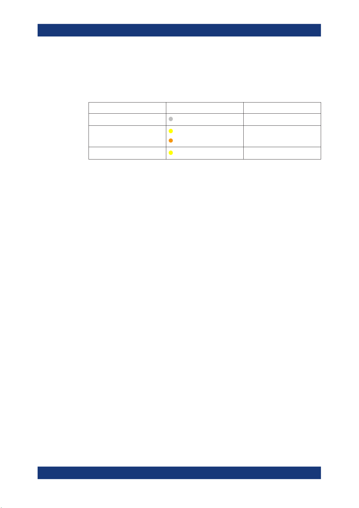
The following table provides an overview of power states, LEDs and power switch positions.
Table 3-2: Overview of power states
State LED Position of power switch
Off
Standby
Ready
gray
yellow
orange
yellow
[0]
[I]
[I]
To switch on the R&S SMB100B
The R&S SMB100B is off but connected to power. See Chapter 3.1.6, "Connecting to
Power", on page 26.
1. Set the switch on the power supply to position [I].
The switch is located on the rear panel.
The LED of the [On/Standby] key is orange.
2. Wait until the oven-controlled oscillator (OCXO) warms up. For the warm-up time,
see data sheet.
3. Press the [On/Standby] key.
Key and LED are located on the front panel.
The LED changes to green. The R&S SMB100B boots.
When starting for the first time, the R&S SMB100B starts with the default settings.
When restarting the instrument, the settings depend on the instrument configuration before shut-down.
See Chapter 9.4, "Saving and Recalling Instrument Settings", on page 197.
When the instrument is switched on, it automatically monitors main functions. You can
query erroneous functions. In addition to automatic monitoring, you can perform maintenance tasks.
See:
●
Chapter 13.4, "Querying Error Messages", on page 532
●
Chapter 15.3, "Performing Maintenance Tasks", on page 544
To shut down the product
The product is in the ready state.
► Press the On/Standby key.
The operating system shuts down. The LED changes to orange.
In the standby state, the power switch circuits and the OCXO are active. To deactivate
them, disconnect the instrument from the power supply.
30User Manual 1178.3711.02 ─ 06
 Loading...