


®
R&S
QuickStep
Test Executive Software
User Manual
(;ÛÌG2)
1177622302
Version 10
User Manual

This manual applies to the following options:
●
R&S QuickStep Test Executive Software (1528.9010.02)
●
R&S QuickStep Test Sequencer Software (1528.9049.02)
●
Development option for R&S QuickStep Test Executive Software
(1528.9026.02)
●
R&S QuickStep license dongle and key card (1528.9003.02)
The firmware of the instrument uses several valuable open source software packages. For information,
see the "Open Source Acknowledgment" document, which is available for download from the customer
web section on GLORIS, the global Rohde & Schwarz information system: https://extranet.rohde-
schwarz.com.
Rohde & Schwarz would like to thank the open source community for their valuable contribution to embedded computing.
© 2018 Rohde & Schwarz GmbH & Co. KG
Mühldorfstr. 15, 81671 München, Germany
Phone: +49 89 41 29 - 0
Fax: +49 89 41 29 12 164
Email: info@rohde-schwarz.com
Internet: www.rohde-schwarz.com
Subject to change – Data without tolerance limits is not binding.
R&S® is a registered trademark of Rohde & Schwarz GmbH & Co. KG.
Trade names are trademarks of the owners.
1177.6223.02 | Version 10 | R&S®QuickStep
The following abbreviations are used throughout this manual: R&S® is abbreviated as R&S.

R&S®QuickStep
Contents
Contents
1 Welcome................................................................................. 9
1.1 Key Features......................................................................................... 9
1.2 Software Components, Product Licensing.......................................11
1.3 Documentation....................................................................................12
1.4 Typographic Conventions.................................................................. 13
1.5 Using the Help.....................................................................................14
1.5.1 Accessing the Help............................................................................... 14
1.5.2 Navigating in the Help...........................................................................15
2 What's New...........................................................................16
3 Introduction to QuickStep...................................................17
3.1 Typical Test Setup...............................................................................17
3.2 Graphical User Interface.................................................................... 18
3.2.1 Test Execution.......................................................................................19
3.2.2 Test Plan Editor.....................................................................................20
3.2.3 Results Viewer...................................................................................... 21
3.2.4 Test Procedure Editor........................................................................... 23
3.2.5 System Configurator............................................................................. 24
3.3 Block Function Development............................................................ 25
4 Concepts.............................................................................. 27
4.1 Test Structures and Their Relations..................................................27
4.2 Test Project..........................................................................................29
4.3 Test Execution Phases....................................................................... 30
4.4 Test Plans............................................................................................ 32
4.4.1 Test Sequence with Several Test Procedures.......................................33
3User Manual 1177.6223.02 ─ 10

R&S®QuickStep
4.4.2 Single-Line Sweep................................................................................ 33
4.5 Test Procedures.................................................................................. 35
4.5.1 Blocks & Connectivity........................................................................... 36
4.5.2 More about Test Execution Phases...................................................... 37
4.5.3 Block Functions.....................................................................................38
4.5.4 Connections between Block Functions, Control Structures.................. 41
4.5.5 Parallel and Synchronized Test Execution ...........................................44
4.6 System Configuration.........................................................................46
4.7 Setting Parameter Values by References......................................... 49
4.8 Handling of RF Attenuations............................................................. 53
4.8.1 General Methods.................................................................................. 54
Contents
4.8.2 Compensation of RF Attenuations via System Configuration Paths.....54
4.9 Limit Handling..................................................................................... 56
4.10 DUT Handling...................................................................................... 62
4.11 Result Handling...................................................................................66
4.11.1 Charts................................................................................................... 66
4.11.2 Live View Results..................................................................................69
4.11.3 Reports................................................................................................. 70
5 Preparing for Use.................................................................81
5.1 Required Hardware, Software and Firmware................................... 81
5.2 Installation........................................................................................... 82
5.2.1 Putting the Smart Card into Operation..................................................82
5.2.2 Installing QuickStep.............................................................................. 83
5.2.3 Installing Optional Software and Firmware........................................... 86
5.2.4 Updating License Keys......................................................................... 86
5.3 Network Configuration....................................................................... 87
5.4 Determining Input and Output Attenuations.................................... 90
4User Manual 1177.6223.02 ─ 10

R&S®QuickStep
Contents
6 Operation..............................................................................92
6.1 Starting QuickStep..............................................................................92
6.2 Executing a Test Project.....................................................................94
6.3 Adding a Parameter Sweep to a Test Plan........................................95
6.4 Setting Values by Reference..............................................................97
6.4.1 Reference to a Test Procedure Parameter........................................... 97
6.4.2 Reference to a Test Project Parameter.................................................98
6.4.3 Reference to a Result Parameter......................................................... 99
6.4.4 Other References................................................................................101
6.5 Using a Block Function Result as Input for Another Block Function
............................................................................................................ 101
6.6 Building a Test Procedure................................................................102
6.7 Evaluating Test Results....................................................................104
6.8 Building a System Configuration.................................................... 105
6.9 Using System Configuration Parameters....................................... 107
6.10 Creating a Report Definition............................................................ 109
6.11 Creating or Modifying a Style Sheet for Reports........................... 112
6.12 Setting Up a Report Including a Subreport.................................... 113
6.13 Using a Shortcut for Test Execution............................................... 115
6.14 Getting Support on Problems.......................................................... 116
7 Block Development............................................................117
7.1 Block Development Concepts......................................................... 118
7.1.1 Block Definition....................................................................................118
7.1.2 Programming Structures..................................................................... 121
7.1.3 Call and Reply of Block Functions...................................................... 124
7.1.4 Code Implementation..........................................................................127
7.1.5 Device Parameters............................................................................. 133
5User Manual 1177.6223.02 ─ 10

R&S®QuickStep
7.1.6 Extension Blocks.................................................................................136
7.1.7 Block Functions for Direct DLL Call.................................................... 137
7.1.8 Quality Control, Logging, Exception/Error Handling........................... 145
7.1.9 Script Block Functions........................................................................ 150
7.1.10 User-Defined GUI............................................................................... 153
7.2 Procedures Related to Block Development................................... 156
7.2.1 Overview: Implementation of New Functionality ................................ 157
7.2.2 Creating a New Block and Adding a Function.................................... 159
7.2.3 Calling a Block Function from Another Block......................................162
7.2.4 Using Device Parameters................................................................... 165
7.2.5 Developing Block Functions for Direct DLL Call................................. 168
Contents
7.2.6 Debugging During Block Development............................................... 172
7.2.7 Debugging During Test Execution.......................................................175
7.2.8 Running QuickStep in Command Line Mode......................................177
7.2.9 Re-Using an R&S Forum Script.......................................................... 178
7.2.10 Creating and Integrating a User-Defined GUI.....................................183
8 Application Examples....................................................... 185
8.1 Calculator.......................................................................................... 185
8.1.1 Test Procedure....................................................................................186
8.1.2 Results................................................................................................ 186
8.2 Control Statements...........................................................................187
8.3 DC PowerSupplies............................................................................ 188
8.3.1 Test Setup and Usage of Components............................................... 188
8.3.2 Test Procedure....................................................................................189
8.4 Dual Instance Power Sensors..........................................................189
8.4.1 Test Setup and Usage of Components............................................... 189
8.4.2 Test Procedure....................................................................................190
6User Manual 1177.6223.02 ─ 10

R&S®QuickStep
8.5 Forum Scripting................................................................................ 191
8.6 Matlab Scripting................................................................................ 191
8.7 Network Analyzer..............................................................................192
8.7.1 Test Setup and Usage of Components............................................... 192
8.7.2 Test Procedure....................................................................................193
8.7.3 Test Plan, Results............................................................................... 194
8.8 OSP Switching Unit.......................................................................... 195
8.8.1 Test Setup and Usage of Components............................................... 195
8.8.2 Test Procedure....................................................................................195
8.8.3 Results................................................................................................ 196
8.9 Reporting........................................................................................... 196
Contents
8.10 RTO Oscilloscope............................................................................. 197
8.10.1 Test Setup........................................................................................... 197
8.10.2 Test Procedure....................................................................................198
8.11 Signal Analyzer................................................................................. 198
8.11.1 Test Procedure.................................................................................... 198
8.12 Visualization...................................................................................... 200
8.13 Positioner Block Solution................................................................ 201
9 Reference........................................................................... 205
9.1 GUI......................................................................................................205
9.1.1 Top Menu Bar......................................................................................205
9.1.2 General GUI Features.........................................................................207
9.1.3 Test Execution.....................................................................................212
9.1.4 Testplan Editor.................................................................................... 214
9.1.5 Results Viewer.................................................................................... 229
9.1.6 Test Procedure Editor......................................................................... 235
9.1.7 System Configurator........................................................................... 248
7User Manual 1177.6223.02 ─ 10

R&S®QuickStep
9.2 Block Development Tool.................................................................. 254
9.2.1 Block Generator.................................................................................. 254
9.2.2 Block Definition File Editor.................................................................. 256
9.2.3 Tabs within the Block Definition File Editor......................................... 258
9.2.4 Info Window........................................................................................ 265
9.3 Block Library..................................................................................... 265
9.3.1 Instrument Blocks............................................................................... 265
9.3.2 Other Blocks....................................................................................... 272
9.3.3 Special Parameter Groups..................................................................287
Contents
Annex..................................................................................288
A File Extensions and File Locations..................................288
B Return Codes in Command Line Mode............................290
C Supported Test Instruments............................................. 292
D MIPI RFFE Communication...............................................293
D.1 Installing the SignalCraft Scout Driver........................................... 296
E Control Interfaces and Protocols..................................... 298
Glossary: Abbreviations and Terms................................ 300
Index................................................................................... 305
8User Manual 1177.6223.02 ─ 10

R&S®QuickStep
Welcome
Key Features
1 Welcome
Welcome to the R&S QuickStep Test Executive software! QuickStep provides a
high-speed test sequencer in combination with a powerful graphical user interface
for the parameterization and control of test execution. Test procedures are
designed in a graphical editor as flow charts based on the provided or additionally
developed test functions.
QuickStep lets you set up and run test plans – sequences of individual tests
together with scheduling and execution information –, to build test procedures and
to evaluate the test results. During test execution, QuickStep controls the test
equipment.
QuickStep includes example test projects for typical test conditions and hardware
setups. It offers facilities to adapt given test plans and their execution schedules
and to develop new ones. Customer extensions can easily be integrated, e.g. for
exploiting or developing special test algorithms.
If you only use the QuickStep OTA basic application (installed with QuickStep,
QS-ATSCAL license required), most test executive features are hidden at the GUI
but used in the background. For details, see the QuickStep ATSCAL OTA Testing
user manual.
1.1 Key Features
General features:
●
High performance:
QuickStep causes a minimum processing overhead. The test execution speed
is comparable to native C++/C# code. Parallel execution of code is supported.
●
User-friendly handling:
Configurations are done via graphical user interface (GUI) and intuitive handling (for example drag & drop). Standard tests need only a minimum configuration effort.
●
High flexibility and wide application range:
– Examples and reference test cases are available and ready to run.
The test packages are optimized regarding time consumption.
9User Manual 1177.6223.02 ─ 10

R&S®QuickStep
– QuickStep is not confined to a certain set of test instruments since stan-
dard communication interfaces are used for controlling the test equipment.
3rd-party instruments are easily integrated.
– Customer-defined test setups and test conditions are supported.
– QuickStep is appropriate for production tests (particularly due to high per-
formance) as well as for test development purposes.
●
Support for developing test functionality and easy integration of customer
code
Test plan configuration:
●
Static and dynamic parameter references
●
Convenient set and sweep functions
●
Search and filter functions
●
Limit handling
Welcome
Key Features
●
Control phases (for example for instrument initialization) around sequences of
test steps
●
Dynamic control statements (loops, if conditions, jumps)
Test results and execution protocol:
●
Diagram for result plots
●
Histogram view for statistical analysis
●
Configurable result charts and live view results
●
Configurable reports
●
Test execution protocol viewer
System configuration management:
●
Graphical representation of the test setup
●
Intuitive building of system configurations with elements from a library
●
Parameter and path mapping for multiple test setups
Development of new tests:
●
Intuitive building of test procedures via flow charts of blocks from a library
●
Control structures (conditions, "If", "Or") and dependencies
●
GUI supported generation of source code templates for new test functions
●
Powerful API to support standard functionality
●
Microsoft Visual Studio® based test function development with C++ or C#
10User Manual 1177.6223.02 ─ 10

R&S®QuickStep
Software Components, Product Licensing
●
Debugging support: Breakpoints allow to pause a test run on well-defined
steps and block functions; single step execution mode is provided
●
Re-use and extension of R&S Forum and MATLAB scripts
●
Support of user-defined dialogs implemented with Windows Forms or WPF
●
Standalone usage of block DLLs
Welcome
1.2 Software Components, Product Licensing
The software has the following components:
●
Test Executive Software
Includes the complete functionality to define tests based on the provided block
functions, to run tests and analyze the results.
Type: R&S QS-APP, included option keys: R&S QS-EXE, R&S QS-EDI, R&S
QS-SEQ
●
Test Sequencer Software
Executes QuickStep tests. This component is used in combination with a
QuickStep application which provides the calling GUI.
Type: R&S QS-SEQ, option key: R&S QS-SEQ
●
Development Option
Enables the creation of new block functions. The Block Development Tool provides the complete interface to integrate user code into QuickStep via MS Visual Studio projects.
Type: R&S QS-DEV, option key: R&S QS-DEV
Additionally required type: R&S QS-APP
●
OTA Basic Application
Provides the OTA ATSCAL view for easy and integrated control of OTA (over
the air) RF radiation testing, particularly for calibration and antenna measurements in combination with an ATS1000. No configuration of a testplan or test
procedure is needed. Test results (total radiated power, gain, radiation pattern)
are also displayed in the view including polar and 3D chart.
Type: R&S QS-ATSCAL, option key: R&S QS-ATSCAL
Additionally required type: R&S QS-SEQ or R&S QS-APP
●
ATSDRV Positioner Driver Package
Provides the functionality to control an ATS-CCP1 antenna positioner with
turntable and one antenna boom.
Type: R&S QS-ATSDRV, free of charge
11User Manual 1177.6223.02 ─ 10

R&S®QuickStep
Documentation
The licensing is realized with a License Dongle to be connected with a USB port
at the PC where QuickStep is used. The license dongle consists of a smart card
and a USB smart card reader. The definition and execution of tests with the Test
Executive Software is limited to 25 steps if the license dongle is not available or
the license is not valid. The development or OTA functionality is only available
with valid license.
Welcome
1.3 Documentation
PDF documentation
The pdf documents are included on the product's USB stick. Most documents are
also accessible after QuickStep installation via the Windows "Start" button and
the folder "R&S QuickStep > Documentation" or via the QuickStep Help menu.
Additionally, the Getting Started is provided as printed document.
The pdf documentation consists of the following documents:
●
Getting Started
Provides basic information about the product and how to install it.
●
User Manual
Provides detailed information about the features of the application and how to
install, configure and use the application. The manual includes descriptions of
the applied mechanisms, step-by-step procedures showing how to carry out
typical tasks, a reference chapter where the GUI elements and their usage are
described, and application examples.
●
OTA Testing User Manual
User manual that is specialized for the OTA ATSCAL component of QuickStep.
●
Release Notes
Contains the most current information on the application, for example latest
changes, news, restrictions.
●
Training Manuals
Provide detailed descriptions how to use QuickStep based on instructive
examples. The descriptions include step-by-step procedures and many hints
on practical usage.
– User Training: Covers all topics related to the usage of QuickStep – except
for the development of new blocks.
12User Manual 1177.6223.02 ─ 10

R&S®QuickStep
Typographic Conventions
– Developer Training: Covers the tasks for developing functional blocks.
Code examples illustrating how user-defined block functions are devel-
oped. The example code can be copied and inserted in programming files
in MS Visual Studio; therefore two versions of the training manual exist:
one for programming in C++, one for programming in C#.
●
Quick Reference
Lists the typically required API functions on a poster.
●
ActiveReports User Guide
Describes how to use the ReportDesigner which is accessible via the Test
Procedure Editor's toolbar. The ReportDesigner allows to create and edit
report definitions and styles for the QuickStep reporting functionality.
Help, CHM documentation
●
The context-sensitive help system is embedded in QuickStep. Press the
"Help" button or the F1 key to access the help from the graphical user interface.
Welcome
●
The QuickStep API description is a help system describing the classes and
files for block development. It is accessible via the Windows "Start" button and
the folder "R&S QuickStep > Help and Manuals" or via the QuickStep Help
menu.
●
Developer documentation (CHM files) of the provided R&S base blocks for reuse of the block functions for the development of 3rd party blocks.
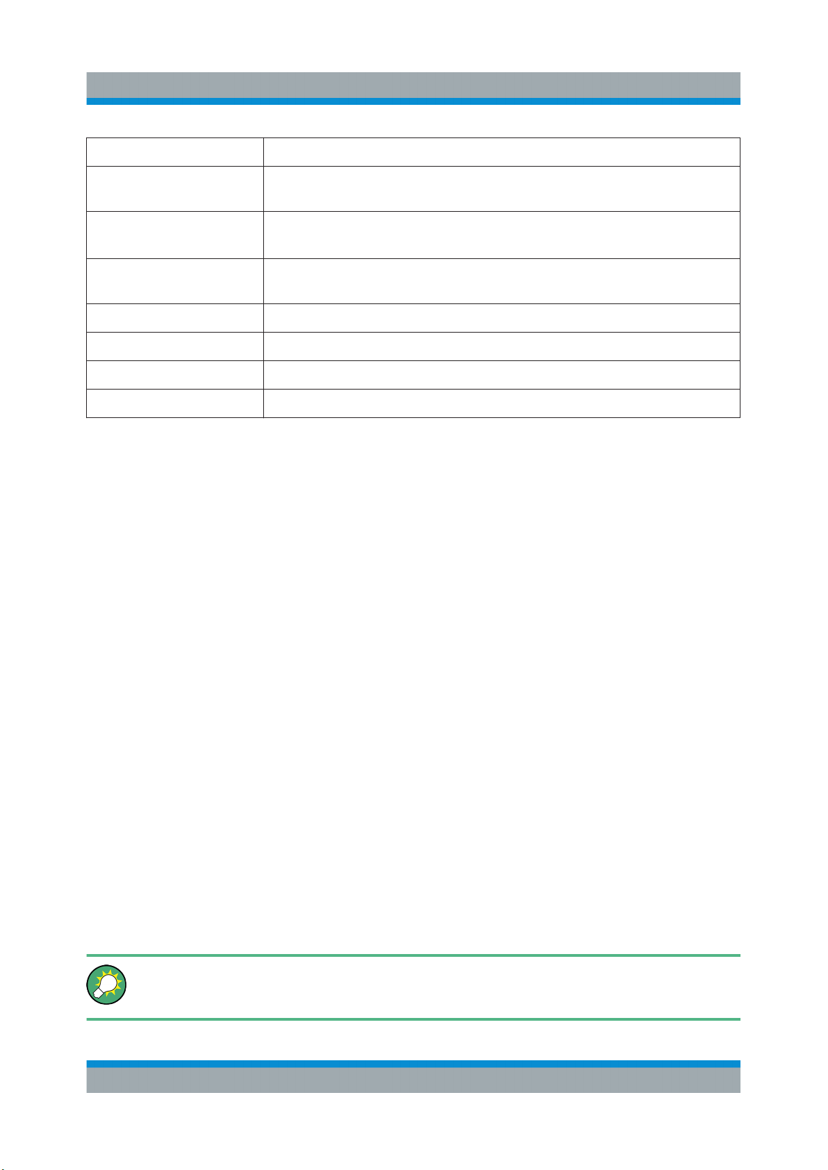
1.4 Typographic Conventions
This document uses the following typographic conventions to make information
easier to access and understand.
Table 1-1: Typographic conventions
Convention Description
"Reference"
"GUI element"
"Menu name > com-
mand"
"Quotation-marks" enclose references or graphical user interface
citations to other documentation parts.
The > symbol indicates a path or an order to follow for making selections on the GUI.
Example: On the taskbar, click "Start > All Programs > ...".
[KEY] [Capital] letters indicate key names. Example: CTRL key.
13User Manual 1177.6223.02 ─ 10
R&S®QuickStep
Welcome
Using the Help
Convention Description
Input Letters in italic indicate a value you must type in as shown. Example:
5400.
code
Link Letters in blue font indicate links that you can follow (underlined).
emphasis Letters in boldface indicate emphasized words.
<variable> Angle brackets enclose variable values. Example: <release>.
| Vertical bar indicates alternate selections - the bar means "or".
... Ellipsis indicates nonessential information omitted from the example.
Letters in fixed-width font indicate file names, commands,
or program code.
Links to the Glossaries are not underlined.
1.5 Using the Help
The help system is integrated into the software. The help system is an integral
part of the product's framework and thus provides information about all application parts that are officially released, independendly of whether the applications
are installed or licensed, or not.
1.5.1 Accessing the Help
Use one of the following options to access the help. Depending on the specific
help calls, several help windows may open in parallel.
●
F1 key
Opens the help. If the selected GUI element provides context-sensitive help,
opens the related help topic.
For example, if a tab is selected, F1 will open a reference description for the
tab.
●
Menu bar
The "Help > R&S QuickStep Help" item opens the Online help ("Help" provides links to other documents, too).
Using ToolTips
Move the pointer over an element to display a short description of it.
14User Manual 1177.6223.02 ─ 10

R&S®QuickStep
Welcome
Using the Help
1.5.2 Navigating in the Help
As in most help systems, you can use common tabs to find the information of
interest. You find the tabs in the left pane: "Contents", "Index" and "Search". The
icons in the toolbar provide further navigation support, see the following table.
Table 1-2: Help menu
Command Description
"Hide"/"Show" Hides or shows the left pane.
"Previous" Opens the previous page of the help directory.
"Next" Opens the next page of the help directory.
"Back" Opens the topics you visited before.
"Home" Shows the start page of the help (legal notice).
"Print" Lets you print the current topic or the selected heading and all
subtopics.
15User Manual 1177.6223.02 ─ 10

R&S®QuickStep
What's New
2 What's New
This document is related to version 4.65 of QuickStep and later.
No new features are described in the document since version 4.50. For more
details, see the Release Notes.
16User Manual 1177.6223.02 ─ 10

R&S®QuickStep
Introduction to QuickStep
Typical Test Setup
3 Introduction to QuickStep
This chapter provides a brief overview over QuickStep for a first orientation. The
given information is not comprehensive and not represented with full complexity.
3.1 Typical Test Setup
Figure 3-1: Schematic test setup (DUT: Device under Test)
Characteristics:
●
QuickStep runs on a PC and controls the test instruments.
●
QuickStep basically commands a sequence of test steps where the values of
one or several test parameters are varied. The results for each test step are
collected and presented within QuickStep.
●
Typically, SCPI commands sent over LAN (or GPIB) control the test instruments. Any other remote control interface might be adapted.
●
The test instruments can be of any type. Examples are generators, analyzers,
power supplies, power sensors, switching devices. The number of used test
instruments is not limited.
●
One or more test instruments provide test signals as input for the DUT. Vice
versa, one or several test instruments gather signals or data from the DUT.
Examples:
– A generator instrument provides an RF signal to the DUT. QuickStep
defines the properties of the RF signal to be transmitted.
– An analyzer instrument receives RF signals from the DUT and measures
their properties. QuickStep gets the results from the analyzer.
– A power supply with variable voltage powers the DUT.
17User Manual 1177.6223.02 ─ 10

R&S®QuickStep
Introduction to QuickStep
Graphical User Interface
3.2 Graphical User Interface
All operational tasks for configuring and executing tests are carried out on the PC.
When starting QuickStep, the "QuickStep" window – the graphical user interface
(GUI) – opens.
Figure 3-2: GUI overview
1 = Menu bar
2 = Tabs
3 = Toolbar
4 = Navigation / browser / library
5 = Main pane
6 = Secondary pane
The GUI is structured with a menu bar, tabs, a toolbar and several panes. The
content to be displayed is distributed in several tabs. The selected tab defines
which type of information is displayed in the different panes. See the descriptions
below for information on the content for single tabs. The entries in the toolbar also
depend on the selected tab.
18User Manual 1177.6223.02 ─ 10

R&S®QuickStep
Introduction to QuickStep
Graphical User Interface
3.2.1 Test Execution
This view becomes relevant when the current test is executed. You can start the
test run and control the test execution.
Figure 3-3: Test Execution
1 = Start the test execution
2 = See and control the execution progress
3 = View the logged messages
4 = Select the block function flow chart of interest
5 = Inspect the current block function
Progress bar
The progress bar shows how far the test has been executed. You can control test
execution, for example resume test execution after a halt due to a breakpoint in
the test plan.
Log Viewer
The Log Viewer protocols the events occurred during operation of QuickStep,
particularly after starting the test execution. The messages are color-coded.
19User Manual 1177.6223.02 ─ 10

R&S®QuickStep
Introduction to QuickStep
Graphical User Interface
Test Procedure Debugger
The "Test Procedure Debugger" allows to check the values of parameters during
test run. It includes the Test Procedure Browser from the Test Procedure Editor
for selecting the block function diagram that contains the block function of interest.
The debugger works together with the progress bar during test run. You can proceed in the test execution step by step with the "Step" button. If you have defined
breakpoints for test steps (to be done in the Testplan Editor) and have clicked the
"Continue" button, the test execution is halted at each breakpoint until you click
"Continue" again.
3.2.2 Test Plan Editor
The "Test Plan Editor" is the initial view of QuickStep. The user prepares a list of
test steps and starts the test execution from the toolbar.
Figure 3-4: Testplan Editor
1 = Select a sequence of test steps (or define groups and sequences)
2 = Inspect and edit the sequence of test steps
3 = Edit parameter values
4 = Start the test plan
Central test step table
In the table, each test step is represented in one row, the columns display the
related parameters. Parameter values can directly be edited in the table after a
double-click.
20User Manual 1177.6223.02 ─ 10

R&S®QuickStep
Each test step is connected to a test procedure by the entry in the "Test Procedure" column. The parameter set of each test step is dynamically adapted
according to the selected test procedure. If test procedure parameters are modified in the test procedure editor, the modifications get effective in the test plan editor after clicking "Update Test Project".
Powerful sweep and set functions allow quick generation of parameter sweeps for
efficient parameter setting of multiple test steps. Multi-parameter sweeps might
be defined within one single test step. Prioritization might be used to keep control
on the order of the parameter sweeps within nested loops.
Panes on the right-hand side
In the "Test Step Parameters" tab, the parameters of a test step are displayed in
vertical order for a better overview and providing a more convenient way to edit
parameters without scrolling. The "TPR Options" tab contains parameters for the
whole test, for example repetitions. The "Test Step Limits" tab shows the configured limits for measurement results.
Introduction to QuickStep
Graphical User Interface
Regarding test development, various settings for logging and debugging are
offered. Breakpoints for debugging and single-step execution can be enabled for
specific test steps.
Test Project Browser on the left-hand side
Multiple test step parameter tables are organized in a tree structure for keeping
an overview of large tests. Control structures can be applied to sequences of test
steps, their parameters are configured in the right pane. "Test Project Parameters" contains static and dynamic global parameters to be configured in the middle pane.
3.2.3 Results Viewer
The results of a test run are displayed in the "Results Viewer".
21User Manual 1177.6223.02 ─ 10

R&S®QuickStep
Figure 3-5: Results Viewer
Introduction to QuickStep
Graphical User Interface
1 = Select a result file
2 = Inspect the result table and select one or more result columns
3 = Inspect the diagram representation of the results for the selected column(s)
4 = Inspect the distribution of result values and check the statistical evaluation
Results File Browser on the left-hand side
The "Result File Browser" helps to keep an overview of large sets of result data.
Each test run generates a new time-stamped folder with a complete set of result
files with measurement and timing results as comma-separated value (CSV) files.
For each DUT, a separate subfolder is created. If results of the type trace are
generated, these are also collected in a DUT-specific subfolder. Additionally, a
copy of the test plan and the execution log is stored as a reference.
When selecting a result file in the Result File Browser, its content is shown as
table in the central area. TestStepsResults.log is the main result file con-
taining the results for each test step. ExecutionProtocol ... .txt contains
all logged messages with timestamp and origin.
Central Results Table
The central "Results Table" shows the results in a table. In case
TestStepsResults.log has been selected, each test step is presented in one
row and each result parameter in one column. If one or several result parameters
22User Manual 1177.6223.02 ─ 10

R&S®QuickStep
in the results table are selected, the results over the test steps (or other configurable running variables) are represented in the diagram on the right-hand side.
Each column of the table offers powerful sort and filter functions. An export filter
makes it possible to export a subset of the table as CSV or XLS file. In case the
table shows the content of the execution protocol, it is possible to export and
reuse SCPI sequences within other test environments (for example).
Analysis panes on the right-hand side
The "Diagram" pane plots the data of a single or multiple columns that are
selected within the result table. Scatter plots are possible, since any result parameter can be selected for the x-axis of the plot. Results can be assigned to colorcoded groups by selecting an additional grouping parameter. Delta markers are
available for measurements.
If results of the trace type are selected, an adopted diagram pane is available.
Traces files can also be loaded directly into the central results table and displayed
with the standard results viewer. Zoom in and out is supported by mouse click,
mouse wheel and diagram bars.
Introduction to QuickStep
Graphical User Interface
The "Histogram & Statistics" pane provides a histogram pane and statistical
analysis of the result data that is selected within the result table.
3.2.4 Test Procedure Editor
A test procedure basically defines what functionality is executed when the test
steps connected to the test procedure are carried out. It is set up as flowchart
with a graphical editor, based on a library of provided functions or user-developed
functions.
23User Manual 1177.6223.02 ─ 10

R&S®QuickStep
Introduction to QuickStep
Graphical User Interface
Figure 3-6: Test Procedure Editor
1 = Select an execution phase
2 = Drag a new block function into the main pane
3 = Select block functions, add block function dependencies, select a block function
4 = Edit the parameters of the selected block function
Control elements such as "If", "Or", “Fork” and “Join” are available to handle execution branches and loops. Conditions achieve a conditional execution of test
functions. All test function parameters can be made available for test parameterization within the test plan editor. Existing test procedures can be modified or
extended without source code development.
The toolbar provides access to tools for developing blocks, handling SCPI commands for connected test instruments, designing reports and integrating scripts.
3.2.5 System Configurator
The "System Configurator" reflects the test setup and can be used for setting the
device- and connection-specific parameters as occurring with the test setup.
24User Manual 1177.6223.02 ─ 10

R&S®QuickStep
Figure 3-7: System Configurator
1 = Drag a symbol into the main area
2 = Connect the symbols
3 = Select an element
4 = Edit the properties (parameters) of the selected element
Introduction to QuickStep
Block Function Development
The main pane displays the used devices (test instruments, components, even
attenuators) and connections. You drag devices from the "Device Library" on the
left pane into the main pane. Then you draw connections between the devices.
On the right side in the "Properties" pane, you can see and edit the properties of
the currently activated device.
The system configurator facilitates the handling of several use cases:
●
Assistance for building up a VISA connection to a test instrument.
●
Automatic calculation of the RF path loss during test execution. Attenuations/
losses for individual components of the system are defined, then one or more
connections and system components are assigned to an RF path.
●
Easy switching between several test benches. Therefore, the system configuration contains the configuration for each of them.
●
Management of system-dependent parameters like connection IDs.
3.3 Block Function Development
The Block Development Tool is provided for defining new test blocks, test functions and the associated function parameters. Based on these definitions, Microsoft Visual Studio C++ or C# projects with source code templates are automatically generated. The templates just have to be extended with user code in order
25User Manual 1177.6223.02 ─ 10

R&S®QuickStep
Introduction to QuickStep
Block Function Development
to create user-specific test functions. The newly developed test functions are
available in the test procedure editor after compilation.
Figure 3-8: Main section of the Block Development Tool
The QuickStep API (application programmer interface) offers a set of functions for
data exchange with other functions and logging of results. Even users with limited
software development experience can implement new test functions with just a
few lines of code. Development experts can exploit all capabilities of Visual Studio for development of complex test functions.
26User Manual 1177.6223.02 ─ 10

R&S®QuickStep
Test Structures and Their Relations
Concepts
4 Concepts
4.1 Test Structures and Their Relations
Test plans, test procedures and blocks
QuickStep organizes a test configuration with the following main structures:
●
Test plan: Contains a sequence of test steps, each one using a set of parameter values, and scheduling information. Each test step is connected with a
test procedure. Multiple test procedures for different test purposes may be
used in one test plan.
●
Test procedure: Defines the test functionality to be applied within a test step.
A test procedure is structured by a flowchart of block functions (see below)
which execute application software. The block functions can be arranged with
certain control structures.
●
Block: Contains a set of functions and one function is selected. A function fulfills a certain task and provides the parameters for user input. Often, a block
reflects the functionality of a test instrument. But it can also represent instrument-independent functions ("software block") or only parts of an instrument's
functionality.
This structure keeps the test steps free from the real test equipment functionality.
The concept of blocks carrying functions allows you to provide, adapt and
develop test algorithms optimized for special test equipment and test conditions.
The blocks in a test procedure can be arranged in parallel or in sequence or in
combination with decision functions.
Figure 4-1: Logical representation of a test (principle)
27User Manual 1177.6223.02 ─ 10
R&S®QuickStep
Concepts
Test Structures and Their Relations
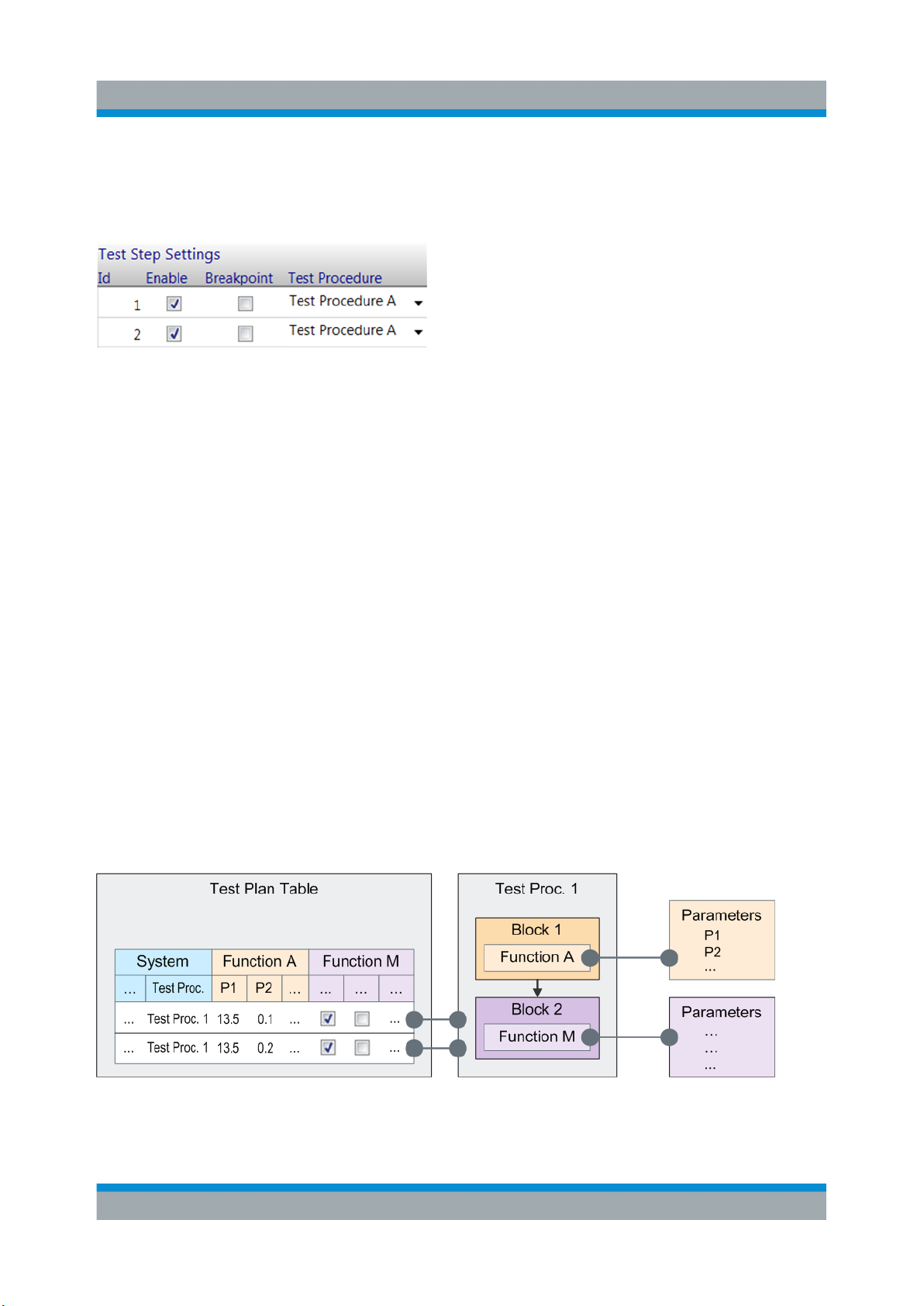
A test step is connected with a test procedure by its Test Procedure value in the
testplan table. See the figure where test steps 1 and 2 are connected to Test Procedure A.
Figure 4-2: Connecting a test step with a test procedure
Parameters
Parameters provide the concrete, quantitative settings used for the test execution,
for example frequency and power values.
The same parameters are related to block functions, test procedures and test
plans as well: The parameters required for specific functionality (for example for
controlling a generator instrument) are defined by block functions. So, they
appear in a test procedure when the related block function is added in the procedure. Afterwards, they get available for the test steps of a test plan table when the
test steps are connected to the test procedure.
In the test plan table, the parameters are displayed as columns, grouped by the
originating functions. Usually, the parameter values are set in the test steps of the
test plan with certain variations over the test steps. When the test is executed, the
functions of the connected test procedure take over these values e.g. for their
communication with the test instruments and calculations. This interplay between
test steps and test procedure is fundamental; a test step without connected test
procedure is undefined.
Figure 4-3: Definition and display of parameters (principle)
28User Manual 1177.6223.02 ─ 10

R&S®QuickStep
The default values of the parameters in the test plan refer to the parameter values
set in the "Properties" section in the "Test Procedure Editor". Parameter values
can also be set by references, see chapter Setting Parameter Values by Referen-
ces.
Additionally, common parameters for a test procedure or even the test project can
be defined.
Test run mechanism
When starting the test execution, the test steps of the test plan are processed
according to the order and the repetitions defined in the test plan. For each test
step reached during the test run, the connected test procedure is called. The test
procedure takes over parameter values from the test step and executes the functions as defined in its blocks and regarding their arrangement.
The sequence of test procedure executions for the test steps is enframed with
some procedure-like control structures (for example "Testrun Before"). Usually,
the term "Test Procedure" is reserved for the procedures related to test steps
only, but if convenient, the additional procedure structures can also be included.
The parameter sets of the control structures also appear around a test step table
and are included in the term "Test Plan" if convenient.
Concepts
Test Project
4.2 Test Project
A test project is the master structure for the components of a QuickStep test. For
each test, it contains the test plan and test procedures as well as result and log
files, various configuration files and other components. The following figure gives
a symbolic overview over the main components, their main substructures and
relations. The blue colored fields correspond with the main GUI partitions (Test
Plan Editor, Results Viewer, Test Procedure Editor and System Configurator). The
system configuration is optional.
29User Manual 1177.6223.02 ─ 10

R&S®QuickStep
Concepts
Test Execution Phases
Figure 4-4: Test project structures and relations (simplified)
See Chapter A, "File Extensions and File Locations", on page 288 for information
about actual file locations.
4.3 Test Execution Phases
An overall test run consists of several phases. Phases which contain block functions are displayed in the "Test Project Browser" within the "Testplan Editor". The
parameters for the currently active phase are displayed in the table area of the
"Testplan Editor". The functionality to be executed for such an item is configured
by block functions in the "Test Procedure Editor".
30User Manual 1177.6223.02 ─ 10
 Loading...