


R&S®NRX
Power Meter
User Manual
(;ÜÅÐ2)
1178556602
Version 09

This manual describes the R&S®NRX (1424.7005K02) with firmware version FW 02.50 and later.
In addition to the base unit, the following options are described:
●
R&S®NRX-B1 (1424.7805K02)
●
R&S®NRX-B4 (1424.8901K02)
●
R&S®NRX-B8 (1424.8301K02)
●
R&S®NRX-B9 (1424.8601K02)
●
R&S®NRX-K2 (1424.9208K02)
●
R&S®NRX-K4 (1424.9308K02)
●
R&S®NRX-K301 (1444.0041K02)
© 2021 Rohde & Schwarz GmbH & Co. KG
Mühldorfstr. 15, 81671 München, Germany
Phone: +49 89 41 29 - 0
Email: info@rohde-schwarz.com
Internet: www.rohde-schwarz.com
Subject to change – data without tolerance limits is not binding.
R&S® is a registered trademark of Rohde & Schwarz GmbH & Co. KG.
Trade names are trademarks of the owners.
1178.5566.02 | Version 09 | R&S®NRX
Throughout this manual, products from Rohde & Schwarz are indicated without the ® symbol , e.g. R&S®NRX is indicated as
R&S NRX.

R&S®NRX
Contents
Contents
1 Safety and regulatory information......................................................11
1.1 Safety Instructions...................................................................................................... 11
1.2 Labels on the product.................................................................................................13
1.3 Warning messages in the documentation................................................................ 14
1.4 Korea certification class B......................................................................................... 14
2 Welcome............................................................................................... 15
2.1 Documentation overview............................................................................................15
2.1.1 Getting started manual..................................................................................................15
2.1.2 User manual..................................................................................................................15
2.1.3 Instrument security procedures.....................................................................................15
2.1.4 Printed safety instructions............................................................................................. 15
2.1.5 Data sheets and brochures........................................................................................... 15
2.1.6 Release notes and open source acknowledgment (OSA)............................................ 16
2.2 Key features.................................................................................................................16
3 Getting started......................................................................................17
3.1 Preparing for use........................................................................................................ 17
3.1.1 Lifting and carrying........................................................................................................17
3.1.2 Unpacking and checking............................................................................................... 17
3.1.3 Choosing the operating site.......................................................................................... 17
3.1.4 Setting up the product................................................................................................... 18
3.1.5 Considerations for test setup........................................................................................ 20
3.1.6 Connecting to power..................................................................................................... 20
3.1.7 Connecting to LAN........................................................................................................ 21
3.1.8 Connecting power sensors............................................................................................21
3.1.9 Connecting USB and external devices..........................................................................23
3.1.10 Switching on or off.........................................................................................................24
3.2 Instrument tour............................................................................................................25
3.2.1 Front panel tour.............................................................................................................25
3.2.2 Rear panel tour............................................................................................................. 29
4 Operating concepts............................................................................. 33
3User Manual 1178.5566.02 ─ 09

R&S®NRX
Contents
4.1 Manual operation........................................................................................................ 33
4.1.1 Start dialog.................................................................................................................... 33
4.1.2 Main measurement dialog.............................................................................................34
4.1.3 Status information......................................................................................................... 36
4.1.4 Notification center......................................................................................................... 37
4.1.5 Selecting the display layout...........................................................................................38
4.1.6 Swapping measurement panes.....................................................................................40
4.1.7 Editing parameters........................................................................................................ 41
4.1.8 Creating and saving screenshots..................................................................................42
4.1.9 Restricting manual operation........................................................................................ 42
4.2 Remote operation........................................................................................................43
4.3 Remote control............................................................................................................44
4.3.1 Switching to remote control (REMOTE)........................................................................ 44
4.3.2 Returning to manual operation (LOCAL).......................................................................45
5 Measurement basics............................................................................46
5.1 Parallel measurements............................................................................................... 46
5.2 Sensor assignment and memory...............................................................................46
5.3 Performing a measurement........................................................................................48
5.4 Limit violation..............................................................................................................49
5.5 Settings conflict.......................................................................................................... 50
6 Measurement and display configuration........................................... 52
6.1 Configuration for all measurement types................................................................. 52
6.1.1 Display settings............................................................................................................. 52
6.1.2 Controlling the measurement........................................................................................ 62
6.1.3 Triggering...................................................................................................................... 63
6.1.4 Measurement settings dialog........................................................................................ 69
6.2 Continuous average....................................................................................................72
6.2.1 Continuous average result display................................................................................ 72
6.2.2 Continuous average settings.........................................................................................73
6.3 Burst average.............................................................................................................. 74
6.3.1 Burst average result display..........................................................................................75
6.3.2 Burst average settings.................................................................................................. 75
6.4 Trace.............................................................................................................................76
4User Manual 1178.5566.02 ─ 09

R&S®NRX
Contents
6.4.1 Trace result display....................................................................................................... 76
6.4.2 Trace settings................................................................................................................77
6.4.3 Trace Marker dialog...................................................................................................... 78
6.5 Pulse analysis............................................................................................................. 81
6.5.1 Pulse analysis result display......................................................................................... 82
6.5.2 Pulse analysis settings..................................................................................................82
6.5.3 Pulse Analysis dialog.................................................................................................... 83
6.6 Time gate......................................................................................................................90
6.6.1 Time gate result display................................................................................................ 91
6.6.2 Time gate settings.........................................................................................................92
6.6.3 Gate Configuration dialog............................................................................................. 94
6.7 Timeslot........................................................................................................................95
6.7.1 Timeslot result display...................................................................................................96
6.7.2 Timeslot settings........................................................................................................... 98
6.7.3 Timeslot Configuration dialog........................................................................................99
6.8 Statistics.................................................................................................................... 101
6.8.1 Statistics result display................................................................................................101
6.8.2 Statistics settings........................................................................................................ 103
6.8.3 Measurement Settings dialog......................................................................................104
6.8.4 Scale Configuration dialog.......................................................................................... 105
6.8.5 Statistics Timing dialog................................................................................................107
6.9 NRT.............................................................................................................................108
6.9.1 NRT result display.......................................................................................................108
6.9.2 NRT settings................................................................................................................109
6.9.3 Measurement Main Configuration dialog.....................................................................113
7 Sensor configuration......................................................................... 115
7.1 Mode settings............................................................................................................ 115
7.2 Correction settings................................................................................................... 119
7.3 Filter settings.............................................................................................................122
7.4 Range settings.......................................................................................................... 126
7.5 NRT measurement type............................................................................................ 128
7.5.1 NRT mode settings......................................................................................................129
7.5.2 NRT correction settings...............................................................................................130
5User Manual 1178.5566.02 ─ 09

R&S®NRX
Contents
7.5.3 NRT filter settings........................................................................................................132
8 Saving and recalling settings........................................................... 134
9 Zeroing sensors................................................................................. 136
10 System settings..................................................................................138
10.1 Connections.............................................................................................................. 138
10.1.1 Network settings..........................................................................................................139
10.1.2 Remote settings.......................................................................................................... 142
10.1.3 Input/output settings (I/O)............................................................................................145
10.1.4 Sensor manager..........................................................................................................151
10.2 Instrument info.......................................................................................................... 154
10.2.1 System info................................................................................................................. 154
10.2.2 Security settings..........................................................................................................157
10.2.3 Option settings............................................................................................................ 162
10.2.4 Help & copyrights........................................................................................................ 165
10.3 Hardware configuration............................................................................................166
10.4 Test............................................................................................................................. 167
10.5 Global settings.......................................................................................................... 168
11 Option management.......................................................................... 170
11.1 Installing a license key............................................................................................. 170
12 Firmware update................................................................................ 171
12.1 Firmware update via PC and USB or ethernet connection................................... 171
12.1.1 Hardware and software requirements......................................................................... 171
12.1.2 Preparing an update....................................................................................................172
12.1.3 Updating the application firmware...............................................................................173
12.2 Firmware update via a USB flash memory stick.................................................... 176
12.2.1 Hardware and software requirements......................................................................... 176
12.2.2 Preparing an update....................................................................................................176
12.2.3 Updating the application firmware...............................................................................177
13 Remote control commands...............................................................178
13.1 Conventions used in SCPI command descriptions............................................... 178
13.2 Common commands.................................................................................................178
6User Manual 1178.5566.02 ─ 09

R&S®NRX
Contents
13.3 Addressing measurements and power sensors.................................................... 187
13.4 Making measurements............................................................................................. 188
13.4.1 Using MEASure?.........................................................................................................188
13.4.2 Using CONFigure and READ?....................................................................................189
13.4.3 Using CONFigure, INITiate and FETCH?................................................................... 190
13.4.4 Configuring one setting at a time................................................................................ 190
13.4.5 Structure of combining commands..............................................................................191
13.5 Starting and ending a measurement....................................................................... 193
13.6 Measurement settings and results.......................................................................... 196
13.6.1 Configuring display and results................................................................................... 197
13.6.2 Configuring the trigger.................................................................................................229
13.6.3 Selecting the measurement........................................................................................ 238
13.6.4 Selecting the power sensor.........................................................................................242
13.6.5 Relative measurements.............................................................................................. 243
13.6.6 Continuous average measurements........................................................................... 245
13.6.7 Burst average measurements..................................................................................... 260
13.6.8 Trace measurements.................................................................................................. 269
13.6.9 Pulse analysis measurements.................................................................................... 279
13.6.10 Time gate measurements............................................................................................295
13.6.11 Timeslot measurements..............................................................................................297
13.6.12 Statistics measurements............................................................................................. 309
13.6.13 NRT measurements.................................................................................................... 319
13.6.14 Querying measurement results................................................................................... 326
13.7 Calculation functions................................................................................................328
13.7.1 Selecting a calculation function...................................................................................328
13.8 Configuring sensors................................................................................................. 330
13.8.1 Setting the frequency.................................................................................................. 330
13.8.2 Sensor modes............................................................................................................. 331
13.8.3 Sensor corrections...................................................................................................... 335
13.8.4 Sensor filters............................................................................................................... 340
13.8.5 Sensor ranges.............................................................................................................348
13.8.6 Standardized signals...................................................................................................351
13.8.7 Frequency selective power sensors............................................................................364
7User Manual 1178.5566.02 ─ 09

R&S®NRX
13.14.1 Presetting.................................................................................................................... 399
13.14.2 Shutdown and reboot.................................................................................................. 400
13.14.3 Firmware update......................................................................................................... 400
13.14.4 Network settings..........................................................................................................403
13.14.5 Remote settings.......................................................................................................... 406
13.14.6 Managing sensors.......................................................................................................409
Contents
13.8.8 NRT measurement type.............................................................................................. 366
13.9 Configuring the test generator................................................................................ 376
13.10 Configuring the analog signal ouput and the trigger input/output...................... 378
13.11 Zeroing.......................................................................................................................387
13.12 Running selftests...................................................................................................... 389
13.13 Managing setups and correction tables................................................................. 392
13.14 System information and configuration................................................................... 399
13.14.7 Instrument information................................................................................................ 410
13.14.8 Date and time settings................................................................................................ 412
13.14.9 Notifications and errors............................................................................................... 415
13.14.10 Locking........................................................................................................................419
13.15 Using the status register.......................................................................................... 419
13.15.1 General status register commands............................................................................. 419
13.15.2 Reading the CONDition part....................................................................................... 420
13.15.3 Reading the EVENt part..............................................................................................421
13.15.4 Controlling the ENABle part........................................................................................ 421
13.15.5 Controlling the negative transition part........................................................................422
13.15.6 Controlling the positive transition part......................................................................... 423
13.16 Remote emulation..................................................................................................... 423
13.16.1 R&S NRP2 compatibility............................................................................................. 424
14 Remote control basics.......................................................................464
14.1 Remote control interfaces and protocols............................................................... 464
14.1.1 USB interface.............................................................................................................. 464
14.1.2 Ethernet interface........................................................................................................465
14.1.3 GPIB interface.............................................................................................................468
14.2 SCPI command structure......................................................................................... 468
14.2.1 Syntax for common commands...................................................................................469
8User Manual 1178.5566.02 ─ 09

R&S®NRX
Contents
14.2.2 Syntax for device-specific commands.........................................................................469
14.2.3 SCPI parameters.........................................................................................................470
14.2.4 Overview of syntax elements...................................................................................... 473
14.2.5 Structure of a command line....................................................................................... 473
14.2.6 Responses to queries................................................................................................. 474
14.3 Command sequence and synchronization............................................................. 475
14.3.1 Preventing overlapping execution............................................................................... 475
14.4 Status reporting system........................................................................................... 475
14.4.1 Hierarchy of the status registers................................................................................. 476
14.4.2 Structure of a SCPI status register..............................................................................477
14.4.3 Status byte (STB) and service request enable register (SRE)....................................479
14.4.4 IST flag and parallel poll enable register (PPE).......................................................... 480
14.4.5 Device status register..................................................................................................480
14.4.6 Questionable status register....................................................................................... 482
14.4.7 Standard event status and enable register (ESR, ESE)............................................. 486
14.4.8 Operation status register.............................................................................................487
15 Troubleshooting................................................................................. 497
15.1 Displaying information............................................................................................. 497
15.2 Notifications.............................................................................................................. 497
15.2.1 Interpreting notifications and their number..................................................................498
15.3 Performing tests........................................................................................................501
15.4 Collecting information for technical support......................................................... 502
15.5 Contacting customer support..................................................................................502
16 Transporting.......................................................................................503
17 Maintenance, storage and disposal................................................. 504
17.1 Cleaning..................................................................................................................... 504
17.2 Storage.......................................................................................................................504
17.3 Disposal..................................................................................................................... 504
Glossary: List of abbreviations........................................................ 505
List of commands.............................................................................. 507
Index....................................................................................................526
9User Manual 1178.5566.02 ─ 09

R&S®NRX
Contents
10User Manual 1178.5566.02 ─ 09

R&S®NRX
Safety and regulatory information
Safety Instructions
1 Safety and regulatory information
The product documentation helps you use the product safely and efficiently. Follow the
instructions provided here and in the following chapters.
Intended use
Combined with the supported R&S power sensors, the R&S NRX base unit is intended
for power measurements in development and production. The supported R&S power
sensors are listed in the data sheet. Observe the operating conditions and performance limits stated in the data sheet.
Target audience
The target audience is developers and technicians. The required skills and experience
in power measurements depend on the used operating concept. While manual operation is suitable for beginners, remote control requires expertise in power measurements.
Depending on the used R&S power sensor, the applications vary greatly. A profound
knowledge of the intended application and test setup is recommended.
Where do I find safety information?
Safety information is part of the product documentation. It warns you of potential dangers and gives instructions on how to prevent personal injury or damage caused by
dangerous situations. Safety information is provided as follows:
●
In Chapter 1.1, "Safety Instructions", on page 11. The same information is provided in many languages as printed "Safety Instructions". The printed "Safety
Instructions" are delivered with the product.
●
Throughout the documentation, safety instructions are provided when you need to
take care during setup or operation.
1.1 Safety Instructions
Products from the Rohde & Schwarz group of companies are manufactured according
to the highest technical standards. To use the products safely, follow the instructions
provided here and in the product documentation. Keep the product documentation
nearby and offer it to other users.
Use the product only for its intended use and within its performance limits. Intended
use and limits are described in the product documentation such as the data sheet,
manuals and the printed "Safety Instructions". If you are unsure about the appropriate
use, contact Rohde & Schwarz customer service.
Using the product requires specialists or specially trained personnel. These users also
need sound knowledge of at least one of the languages in which the user interfaces
and the product documentation are available.
11User Manual 1178.5566.02 ─ 09

R&S®NRX
Safety and regulatory information
Safety Instructions
Never open the casing of the product. Only service personnel authorized by
Rohde & Schwarz are allowed to repair the product. If any part of the product is damaged or broken, stop using the product. Contact Rohde & Schwarz customer service at
http://www.customersupport.rohde-schwarz.com.
Lifting and carrying the product
The maximum weight of the product is provided in the data sheet. To move the product
safely, you can use lifting or transporting equipment such as lift trucks and forklifts. Follow the instructions provided by the equipment manufacturer.
Choosing the operating site
Only use the product indoors. The product casing is not waterproof. Water that enters
can electrically connect the casing with live parts, which can lead to electric shock,
serious personal injury or death if you touch the casing. If Rohde & Schwarz provides
accessories designed for your product, e.g. a carrying bag, you can use the product
outdoors.
Unless otherwise specified, you can operate the product up to an altitude of 2000 m
above sea level. The product is suitable for pollution degree 2 environments where
nonconductive contamination can occur. For more information on environmental conditions such as ambient temperature and humidity, see the data sheet.
Setting up the product
Always place the product on a stable, flat and level surface with the bottom of the product facing down. If the product is designed for different positions, secure the product so
that it cannot fall over.
If the product has foldable feet, always fold the feet completely in or out to ensure stability. The feet can collapse if they are not folded out completely or if the product is
moved without lifting it. The foldable feet are designed to carry the weight of the product, but not an extra load.
If stacking is possible, keep in mind that a stack of products can fall over and cause
injury.
If you mount products in a rack, ensure that the rack has sufficient load capacity and
stability. Observe the specifications of the rack manufacturer. Always install the products from the bottom shelf to the top shelf so that the rack stands securely. Secure the
product so that it cannot fall off the rack.
Connecting to power
The product is an overvoltage category II product. Connect the product to a fixed
installation used to supply energy-consuming equipment such as household appliances and similar loads. Keep in mind that electrically powered products have risks, such
as electric shock, fire, personal injury or even death.
Take the following measures for your safety:
●
Before switching on the product, ensure that the voltage and frequency indicated
on the product match the available power source. If the power adapter does not
adjust automatically, set the correct value and check the rating of the fuse.
12User Manual 1178.5566.02 ─ 09
R&S®NRX
Safety and regulatory information
Labels on the product
●
Only use the power cable delivered with the product. It complies with country-specific safety requirements. Only insert the plug into an outlet with protective conductor terminal.
●
Only use intact cables and route them carefully so that they cannot be damaged.
Check the power cables regularly to ensure that they are undamaged. Also ensure
that nobody can trip over loose cables.
●
If the product needs an external power supply, use the power supply that is delivered with the product or that is recommended in the product documentation or a
power supply that conforms to the country-specific regulations.
●
Only connect the product to a power source with a fuse protection of maximum
20 A.
●
Ensure that you can disconnect the product from the power source at any time.
Pull the power plug to disconnect the product. The power plug must be easily
accessible. If the product is integrated into a system that does not meet these
requirements, provide an easily accessible circuit breaker at the system level.
Cleaning the product
Use a dry, lint-free cloth to clean the product. When cleaning, keep in mind that the
casing is not waterproof. Do not use liquid cleaning agents.
Meaning of safety labels
Safety labels on the product warn against potential hazards.
Potential hazard
Read the product documentation to avoid personal injury or product damage.
Electrical hazard
Indicates live parts. Risk of electric shock, fire, personal injury or even death.
Hot surface
Do not touch. Risk of skin burns. Risk of fire.
Protective conductor terminal
Connect this terminal to a grounded external conductor or to protective ground. This connec-
tion protects you against electric shock if an electric problem occurs.
1.2 Labels on the product
Labels on the casing inform about:
●
Personal safety, see "Meaning of safety labels" on page 13
●
Environment safety, see Table 1-1
●
Identification of the product, see Chapter 3.2.2.7, "Name plate", on page 31.
13User Manual 1178.5566.02 ─ 09

R&S®NRX
Safety and regulatory information
Korea certification class B
Table 1-1: Labels regarding environment safety
Labeling in line with EN 50419 for disposal of electrical and electronic equipment after the product has come to the end of its service life.
For more information, see "Disposing electrical and electronic equipment" on page 504.
1.3 Warning messages in the documentation
A warning message points out a risk or danger that you need to be aware of. The signal word indicates the severity of the safety hazard and how likely it will occur if you do
not follow the safety precautions.
WARNING
Potentially hazardous situation. Could result in death or serious injury if not avoided.
CAUTION
Potentially hazardous situation. Could result in minor or moderate injury if not avoided.
NOTICE
Potential risks of damage. Could result in damage to the supported product or to other
property.
1.4 Korea certification class B
이 기기는 가정용(B급) 전자파 적합기기로서 주로 가정에서 사용하는 것을 목적으로 하
며, 모든 지역에서 사용할 수 있습니다.
14User Manual 1178.5566.02 ─ 09

R&S®NRX
Welcome
Documentation overview
2 Welcome
This chapter provides an overview of the user documentation and an introduction to
the R&S NRX.
2.1 Documentation overview
This section provides an overview of the R&S NRX user documentation. Unless specified otherwise, you find the documents on the R&S NRX product page at:
www.rohde-schwarz.com/manual/NRX
2.1.1 Getting started manual
Introduces the R&S NRX and describes how to set up and start working with the product. A printed version is delivered with the instrument.
2.1.2 User manual
Contains the description of all instrument modes and functions. It also provides an
introduction to remote control, a complete description of the remote control commands
with programming examples, and information on maintenance, instrument interfaces
and error messages. Includes the contents of the getting started manual .
The user manual is provided on the R&S NRX for download under:
[System] > "Instrument Info" > "Help & Copyrights"
For further details, see Chapter 10.2.4, "Help & copyrights", on page 165.
2.1.3 Instrument security procedures
Deals with security issues when working with the R&S NRX in secure areas. It is available for download on the Internet.
2.1.4 Printed safety instructions
Provides safety information in many languages. The printed document is delivered with
the product.
2.1.5 Data sheets and brochures
The data sheet contains the technical specifications of the R&S NRX. It also lists the
firmware applications and their order numbers, and optional accessories.
15User Manual 1178.5566.02 ─ 09

R&S®NRX
Welcome
Key features
The brochure provides an overview of the instrument and deals with the specific characteristics.
See www.rohde-schwarz.com/brochure-datasheet/NRX
2.1.6 Release notes and open source acknowledgment (OSA)
The release notes list new features, improvements and known issues of the current
firmware version.
The open source acknowledgment and the license texts of open source software packages used in the R&S NRX software are provided under:
[System] > "Instrument Info" > "Help & Copyrights"
For further details, see Chapter 10.2.4, "Help & copyrights", on page 165.
See www.rohde-schwarz.com/firmware/NRX
2.2 Key features
The R&S NRX supports:
●
Easy RF power measurements
●
Multi-channel measurements
●
RF pulse analysis
●
System integration
The R&S NRX is a versatile, user-friendly base unit.
●
Straightforward numerical and graphical display of measured values, plus intuitive
operation with touchscreen-based graphical user interface
●
Supports up to four R&S NRP and R&S NRQ6 power sensors.
●
Supports all sensor-dependent measurement functions
●
Hardware interfaces for remote control and triggering
●
Code emulation of the R&S NRP2
●
Optional high-precision CW and pulse mode reference source module
●
Optional power reflection measurements with R&S NRT‑Zxx directional power sensors
See also the R&S NRX fact sheet at www.rohde-schwarz.com.
16User Manual 1178.5566.02 ─ 09

R&S®NRX
Getting started
Preparing for use
3 Getting started
3.1 Preparing for use
Here, you can find basic information about setting up the product for the first time.
● Lifting and carrying..................................................................................................17
● Unpacking and checking.........................................................................................17
● Choosing the operating site.................................................................................... 17
● Setting up the product.............................................................................................18
● Considerations for test setup.................................................................................. 20
● Connecting to power............................................................................................... 20
● Connecting to LAN..................................................................................................21
● Connecting power sensors......................................................................................21
● Connecting USB and external devices....................................................................23
● Switching on or off...................................................................................................24
3.1.1 Lifting and carrying
See "Lifting and carrying the product" on page 12.
The R&S NRX weighs below 3 kg, details are provided in the data sheet. Due to the
low weight, you can move the R&S NRX easily.
3.1.2 Unpacking and checking
1. Unpack the product carefully.
2. Retain the original packing material. Use it when transporting or shipping the product later.
3. Using the delivery notes, check the equipment for completeness.
4. Check the equipment for damage.
If the delivery is incomplete or equipment is damaged, contact Rohde & Schwarz.
3.1.3 Choosing the operating site
Specific operating conditions ensure proper operation and avoid damage to the product and connected devices. For information on environmental conditions such as ambient temperature and humidity, see the data sheet.
See also "Choosing the operating site" on page 12.
17User Manual 1178.5566.02 ─ 09

R&S®NRX
Electromagnetic compatibility classes
The electromagnetic compatibility (EMC) class indicates where you can operate the
product. The EMC class of the product is given in the data sheet under "General data".
●
Class B equipment is suitable for use in:
– Residential environments
– Environments that are directly connected to a low-voltage supply network that
supplies residential buildings
●
Class A equipment is intended for use in industrial environments. It can cause
radio disturbances in residential environments due to possible conducted and radiated disturbances. It is therefore not suitable for class B environments.
If class A equipment causes radio disturbances, take appropriate measures to
eliminate them.
3.1.4 Setting up the product
See also:
●
"Setting up the product" on page 12
●
"Intended use" on page 11
Getting started
Preparing for use
3.1.4.1 Placing the product on a bench top
The R&S NRX is a small and lightweight product. You can stack the R&S NRX with
other products, but place the R&S NRX on top. In the following procedure, the weight
indication for stacking refers to the most common design of larger Rohde & Schwarz
instruments. Verify the load suitable for your product before stacking.
To place the product on a bench top
1. Place the product on a stable, flat and level surface. Ensure that the surface can
support the weight of the product. For information on the weight, see the data
sheet.
CAUTION! Foldable feet can collapse. See "Setting up the product" on page 12.
2.
Always fold the feet completely in or out. With folded-out feet, do not place any-
thing on top or underneath the product.
WARNING! A stack of products can fall over and cause injury. Never stack more
3.
than three products on top of each other. Instead, mount them in a rack.
Stack as follows:
● If the products have foldable feet, fold them in completely.
● It is best if all products have the same dimensions (width and length). If the
products have different dimensions, stack according to size and place the
smallest product on top.
● Do not exceed the permissible total load placed on the product at the bottom of
the stack:
– 50 kg when stacking products of identical dimensions (left figure).
18User Manual 1178.5566.02 ─ 09

R&S®NRX
– 25 kg when stacking smaller products on top (middle figure).
Left = Stacked correctly, same dimensions
Middle = Stacked correctly, different dimensions
Right = Stacked incorrectly, too many products
NOTICE! Overheating can damage the product.
4.
Prevent overheating as follows:
Getting started
Preparing for use
● Keep a minimum distance of 10 cm between the fan openings of the product
and any object in the vicinity.
● Do not place the product next to heat-generating equipment such as radiators
or other products.
3.1.4.2 Mounting the product in a rack
To prepare the rack
1. Observe the requirements and instructions in "Setting up the product" on page 12.
NOTICE! Insufficient airflow can cause overheating and damage the product.
2.
Design and implement an efficient ventilation concept for the rack.
To mount the product in a rack
1. Use an adapter kit to prepare the product for rack mounting.
a) Order the rack adapter kit designed for the product. For the order number, see
data sheet.
b) Mount the adapter kit. Follow the assembly instructions provided with the
adapter kit.
2. Grab the product by the handles and push it onto the shelf until the rack brackets fit
closely to the rack.
3. Tighten all screws on the rack brackets to secure the product in the rack.
To unmount the product from a rack
1. Loosen the screws at the rack brackets.
19User Manual 1178.5566.02 ─ 09

R&S®NRX
2. Remove the product from the rack.
3. If placing the product on a bench top again, unmount the adapter kit from the product. Follow the instructions provided with the adapter kit.
3.1.5 Considerations for test setup
Cable selection and electromagnetic interference (EMI)
Electromagnetic interference (EMI) can affect the measurement results.
To suppress electromagnetic radiation during operation:
●
Use high-quality shielded cables, for example, double-shielded RF and LAN
cables.
●
Always terminate open cable ends.
●
Ensure that connected external devices comply with EMC regulations.
●
Do not use USB connecting cables exceeding 5 m.
Getting started
Preparing for use
Preventing electrostatic discharge (ESD)
Electrostatic discharge is most likely to occur when you connect or disconnect a DUT.
NOTICE! Risk of electrostatic discharge. Electrostatic discharge can damage the
►
electronic components of the product and the device under test (DUT).
Ground yourself to prevent electrostatic discharge damage:
a) Use a wrist strap and cord to connect yourself to ground.
b) Use a conductive floor mat and heel strap combination.
3.1.6 Connecting to power
The R&S NRX can be used with different AC power voltages and adapts itself automatically to them. Adjusting the R&S NRX to a particular AC supply voltage is therefore
not required. Refer to the data sheet for the requirements of voltage and frequency.
For safety information, see "Connecting to power" on page 12.
1. Plug the AC power cable into the AC power connector on the rear panel of the
product. Only use the AC power cable delivered with the product.
2. Plug the AC power cable into a power outlet with ground contact.
The required ratings are listed next to the AC power connector and in the data
sheet.
Further information:
●
Chapter 3.2.2.5, "AC supply and power switch", on page 30
20User Manual 1178.5566.02 ─ 09
R&S®NRX
3.1.8.1 Sensor connectors A to D
3.1.7 Connecting to LAN
See Chapter 10.1.1, "Network settings", on page 139.
3.1.8 Connecting power sensors
The R&S NRX supports a wide range of R&S power sensors. See the data sheet for
detailed information.
Depending on the power sensor, you have different choices for connecting power sensors.
See Chapter 3.2.1.1, "Sensor connectors A and B", on page 25 and Chapter 3.2.2.8,
"Sensor connectors C and D", on page 32.
Suitable for:
●
R&S NRP power sensors: R&S NRP xxS/T/A USB and R&S NRPxxSN/TN/AN
LAN models
●
R&S NRQ6
●
R&S NRP‑Zxx power sensors
Getting started
Preparing for use
Sample Clock I/O (Default: 120 MHz)
LAN PoE+
Host
Interface
LO I/0
3
4
NRQ6
Frequency Selective Power Sensor
1
5 6
2
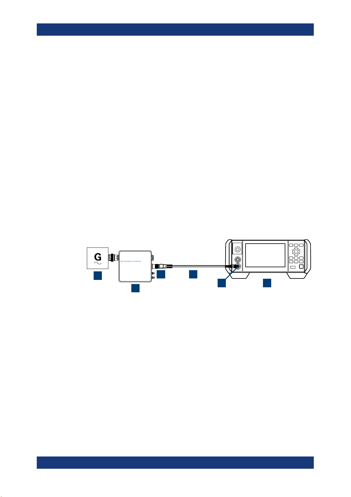
Figure 3-1: Setup with an R&S
1 = Signal source
2 = R&S power sensor
3 = Host Interface connector
4 = R&S NRP‑ZK8
5 = Sensor connector of the R&S NRX
6 = R&S NRX
power sensor (example)
Use an R&S NRP‑ZK8 cable to connect an R&S power sensor to the R&S NRX. If you
use an R&S NRP‑ZK6 cable, the reference clock and trigger are not supported.
1. 8-pin female connector of R&S NRP‑ZK8:
a) Insert the screw-lock cable connector into the host interface of the R&S power
sensor.
b) Tighten the union nut manually.
2. 8-pin male connector of R&S NRP‑ZK8:
a) Insert this connector into one of the sensor ports of the R&S NRX.
21User Manual 1178.5566.02 ─ 09

R&S®NRX
3.1.8.2 Optional interface for R&S NRT-Z sensors (R&S NRX-B9)
Getting started
Preparing for use
3. Connect the RF connector of the R&S power sensor to the signal source. For
details, see the user manual of the R&S power sensor.
Note: Incorrectly connecting/disconnecting an R&S power sensor can damage the
power sensor or lead to erroneous results.
See Chapter 3.2.1.2, "Module bay", on page 26.
Suitable for R&S NRT‑Zxx directional power sensors.
Communication between the R&S NRT‑Zxx directional power sensor and a base unit is
only possible with a baud rate setting of 38400 Bd. This setting is the factory default
that must be restored if the setting was changed. If the R&S NRT‑Zxx directional power
sensor is not recognized by the base unit, check that the baud rate setting of the
R&S NRT‑Zxx directional power sensor is 38400 Bd.
See the manual of the R&S NRT‑Zxx directional power sensor for details.
The arrow on the power sensor casing shows the forward power flow.
1
2
Figure 3-2: Connecting to source and load
1 = source
2 = port 1 (RF connector)
3 = R&S NRT‑Zxx directional power sensor
4 = port 2 (RF connector)
5 = load
6 = host interface connector
3
4
To connect the R&S NRT‑Zxx directional power sensor
5
6
Connect the R&S NRT‑Zxx directional power sensor between source and load of your
test setup as follows.
1. Connect RF connector (2, port 1) to the source.
a) Insert RF connector (2) straight into the RF connector of the source. Take care
not to tilt the R&S NRT‑Zxx directional power sensor.
22User Manual 1178.5566.02 ─ 09

R&S®NRX
Getting started
Preparing for use
b) Tighten the RF connector securely by hand.
2. Connect RF connector (4, port 2) to the load.
a) Insert RF connector (4) straight into the RF connector of the load. Take care
not to tilt the R&S NRT‑Zxx directional power sensor.
b) Tighten the RF connector tightly by hand.
During the measurement, the RF power flow can be high. Power leakage has
the risk of electric shock and severe skin burns.
3. Connect the host interface connector of the R&S NRT‑Zxx directional power sensor
(6) to the interface for R&S NRT-Z sensors (R&S NRX-B9).
To disconnect the R&S NRT‑Zxx directional power sensor
CAUTION! Risk of electric shock and severe skin burns. During the measurement,
1.
the RF power flow can be high.
Switch off the RF power before touching the RF connectors.
2. Unscrew the RF connectors by hand.
3. Disconnect the cable of the R&S NRT‑Zxx directional power sensor (6) from the
interface for R&S NRT-Z sensors (R&S NRX-B9).
3.1.8.3 LAN interface
See Chapter 3.2.2.2, "Ethernet interface", on page 30.
Suitable for LAN power sensors.
R&S power sensors that are connected to the LAN interface are not recognized automatically. Add them, see "To add a LAN power sensor" on page 151.
3.1.8.4 USB 2.0 host interfaces
See Chapter 3.2.1.5, "USB host interface", on page 29 and Chapter 3.2.2.4, "USB
host interface", on page 30.
Suitable for USB power sensors. You can increase the number of connected power
sensors by using USB hubs.
3.1.9 Connecting USB and external devices
Apart from connecting power sensors, you can use the USB interfaces to connect USB
devices. You can increase the number of connected devices by using USB hubs.
Due to the large number of available USB devices, there is almost no limit to the possible expansions. In the following, useful USB devices are listed exemplarily:
●
Memory stick for easy transfer of data to/from a computer (e.g. firmware updates).
●
Mouse if you prefer this way of operation over a touchscreen.
23User Manual 1178.5566.02 ─ 09

R&S®NRX
3.1.10 Switching on or off
Getting started
Preparing for use
Table 3-1: Overview of power states
Status LED Position of power switch
Off Off [0]
Standby
Ready
orange
green
[I]
[I]
To switch on the product
The product is off but connected to power.
1. Set the switch on the power supply to position [I]. See Chapter 3.2.2.5, "AC supply
and power switch", on page 30.
The LED of the [standby] key is orange. See Chapter 3.2.1.6, "On/standby key",
on page 29.
2. Press the [standby] key.
The LED changes to green. The product boots.
See Chapter 4.1.1, "Start dialog", on page 33.
If the previous session ended regularly, the product uses the settings from the last
session.
3. If you want to return to a defined initial state, perform a preset.
See "Preset" on page 135.
To shut down the product
The product is in the ready state.
► Press the [standby] key.
The operating system shuts down. The LED changes to orange.
To disconnect from power
The product is in the standby state.
NOTICE! Risk of data loss. If you disconnect the product from power when it is in
1.
the ready state, you can lose settings and data. Shut it down first.
Set the switch on the power supply to position [0].
The LED of the standby key is switched off.
2. Disconnect the product from the power source.
Further information:
●
Chapter 8, "Saving and recalling settings", on page 134
●
Chapter 3.2.1.6, "On/standby key", on page 29
24User Manual 1178.5566.02 ─ 09

R&S®NRX
Getting started
Instrument tour
3.2 Instrument tour
The meanings of the labels on the product are described in Chapter 1.2, "Labels on the
product", on page 13.
● Front panel tour.......................................................................................................25
● Rear panel tour....................................................................................................... 29
3.2.1 Front panel tour
8
1
7
6
2
Figure 3-3: Front panel of the R&S NRX
1 = Module bay for optional connectors, see Chapter 3.2.1.2, "Module bay", on page 26.
2 = Sensor connectors A and B, see Chapter 3.2.1.1, "Sensor connectors A and B", on page 25.
3 = Touchscreen, see Chapter 3.2.1.3, "Touchscreen", on page 27.
4 = USB host interface, see Chapter 3.2.1.5, "USB host interface", on page 29.
5 = On/standby key, see Chapter 3.2.1.6, "On/standby key", on page 29.
6, 8 = Keys, see Chapter 3.2.1.4, "Keys", on page 27.
7 = Cursor keys, see "Cursor keys" on page 28.
3.2.1.1 Sensor connectors A and B
See (2) in Figure 3-3.
Sensor connectors A and B are used to connect the R&S NRP power sensors and the
R&S NRQ6. For details on the supported power sensors, see the data sheet.
The complete functional range, including external trigger and reference clock for the
synchronization of connected sensors, is provided by these connectors.
Further information:
●
Chapter 3.1.8, "Connecting power sensors", on page 21
3 4 5
25User Manual 1178.5566.02 ─ 09
R&S®NRX
3.2.1.2 Module bay
Getting started
Instrument tour
See (1) in Figure 3-3.
Two options fit in this bay. If you have both options, you can exchange them, see "To
exchange the option" on page 26.
If no option is installed, the module bay is closed by a cover.
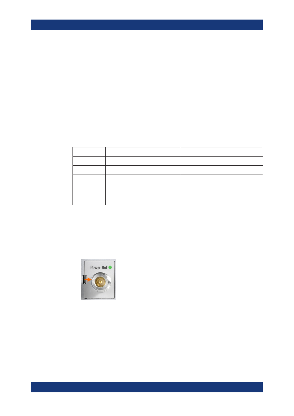
Sensor check source (R&S NRX-B1)
Used as a power reference for testing the connected power sensors and the cabling.
The LED of the sensor check source (R&S NRX-B1) shows the state, see Table 3-2.
You can remove the option and send it to Rohde & Schwarz for calibration. Contact the
Rohde & Schwarz customer service.
Table 3-2: Possible states
Illumination State Signal Output setting
Off No signal is generated. "Off"
Steady green Continuous wave is output. "CW"
Blinking green Pulse signal is output. "Pulse"
Blinking red Settings conflict exists.
For example if "Pulse" is set and the
power level is set to 20 dBm.
"CW" or "Pulse"
Interface for R&S NRT-Z sensors (R&S NRX-B9)
Provides an optional power sensor interface to connect an R&S NRT‑Zxx power sensor. For supported power sensors, see the data sheet.
To exchange the option
1. Press the latch to the right, using your thumb nail or a small pen.
2. Pull the option from its casing.
3. Insert the other option.
4. Press until you hear a click when the latch locks.
Further information:
●
Chapter 3.1.8, "Connecting power sensors", on page 21
●
"Sensor Check Source tab" on page 146
26User Manual 1178.5566.02 ─ 09

R&S®NRX
3.2.1.3 Touchscreen
Getting started
Instrument tour
●
Chapter 13.9, "Configuring the test generator", on page 376
●
Chapter 3.1.8.2, "Optional interface for R&S NRT-Z sensors (R&S NRX-B9)",
on page 22
See (3) in Figure 3-3.
The R&S NRX displays results in panes. Depending on the measurement mode, values are displayed digitally or graphically.
False triggers can occur
If an object (e.g. a human finger) that is charged with static electricity is brought near
the touch panel, false triggers can occur.
This behavior is caused by the principle of operation of a PCAP (projected capacitive)
touch panel.
Further information:
●
3.2.1.4 Keys
See (4) in Figure 3-3.
[Esc] / Local
If you press shortly:
●
●
●
●
If you press and hold:
●
Further information:
●
●
Screenshot
Creates a screenshot of the current display.
See Chapter 4.1.8, "Creating and saving screenshots", on page 42.
Remote command:
SYSTem:HCOPy on page 229
"Using the touchscreen" on page 33
Changes to the next-higher hierarchy level.
Escapes from the entry mode in text boxes and lists.
Closes dialogs without losing any entries that have been made.
Switches from remote control mode (all controls disabled) to manual operation.
Goes to the start dialog that shows an overview of the active measurements.
See Chapter 4.1.1, "Start dialog", on page 33.
"Going back to a higher hierarchy level" on page 33
Chapter 4.3.2, "Returning to manual operation (LOCAL)", on page 45
[1Trig] / Delete
●
Controls the measurements depending on the trigger mode:
– For all trigger modes except "Single", starts and stops the measurement.
– For the "Single" trigger mode, enables and triggers the measurement.
27User Manual 1178.5566.02 ─ 09

R&S®NRX
Getting started
Instrument tour
Changes of the trigger state apply to all measurements.
See also "Trigger Mode" on page 66.
●
Resets the auxiliary values that provide additional information about the measured
values.
See also "Auxiliary Values" on page 55.
●
Deletes numbers or text in a field so that you can enter a new value.
Enter
●
Confirms entries in text fields, dialogs and selections in lists.
●
Shows a frame around the control in focus. You can change the focus using the
Cursor keys.
[Freq]
Sets the carrier frequency of the applied signal. This value is used for frequencyresponse correction of the measurement result.
Remote command:
[SENSe<Sensor>:]FREQuency[:CW] on page 330
Favorites
Reserved for future use.
[Preset]
Opens the "Save / Recall / Preset" dialog.
See Chapter 8, "Saving and recalling settings", on page 134.
If you press [Preset] again, the preset function starts.
See "Preset" on page 135.
If you press the [Preset] key during booting, the R&S NRX starts with the factory
default state.
[Zero]
Pressing [Zero] opens the "Zeroing Sensors" dialog.
If you press [Zero] again, "Zero All Sensors" starts.
Also displays status information:
●
Zeroing status
●
Sensor status
[System]
Opens the "System Overview" dialog.
See Chapter 10, "System settings", on page 138.
Cursor keys
See (5) in Figure 3-3.
The cursor keys are context-sensitive. The control in focus is indicated by a focus
frame. Use the cursor keys as follows:
●
Selecting an element in the navigation pane.
●
Selecting the active pane.
●
Selecting an element from a list.
28User Manual 1178.5566.02 ─ 09
R&S®NRX
3.2.1.5 USB host interface
3.2.1.6 On/standby key
Getting started
Instrument tour
●
Moving the cursor in text boxes.
●
Changing the value of an entry in a text box.
See (6) in Figure 3-3.
USB 2.0 (universal serial bus) interface of the type A (host USB). Used to connect:
●
USB power sensors
●
External devices like a keyboard, mouse, or memory stick
Further information:
●
Chapter 3.1.8.4, "USB 2.0 host interfaces", on page 23
●
Chapter 3.1.9, "Connecting USB and external devices", on page 23
See (7) in Figure 3-3.
The on/standby key switches between standby and ready state, if the power switch is
set to [I].
Further information:
●
Chapter 3.2.2.5, "AC supply and power switch", on page 30
●
Chapter 3.1.10, "Switching on or off", on page 24
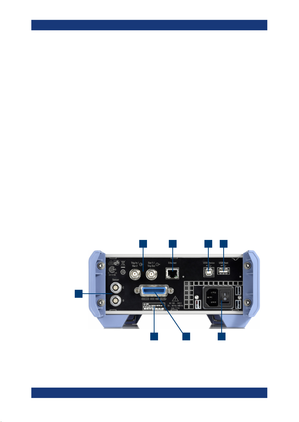
3.2.2 Rear panel tour
1
2 3 4 5
Figure 3-4: Rear panel of the R&S NRX
678
29User Manual 1178.5566.02 ─ 09

R&S®NRX
3.2.2.1 Trig In / Out 2 and Out 1 / Trig Out connectors
Getting started
Instrument tour
1 = Sensor connectors C and D (optional), used to connect R&S power sensors, see Chapter 3.2.2.8, "Sen-
sor connectors C and D", on page 32.
2 = Trig In / Out 2 and Out 1 / Trig Out connectors, see Chapter 3.2.2.1, "Trig In / Out 2 and Out 1 / Trig Out
connectors", on page 30.
3 = Ethernet interface, see Chapter 3.2.2.2, "Ethernet interface", on page 30.
4 = USB device interface, see Chapter 3.2.2.3, "USB device interface", on page 30.
5 = USB host interface, see Chapter 3.2.2.4, "USB host interface", on page 30.
6 = AC supply and power switch, see Chapter 3.2.2.5, "AC supply and power switch", on page 30.
7 = IEC 625/IEEE 488 interface, optional, see Chapter 3.2.2.6, "IEC 625/IEEE 488 interface", on page 31.
8 = Name plate, see Chapter 3.2.2.7, "Name plate", on page 31
See (1) in Figure 3-4.
The Out 1 / Trig Out BNC connectors supply an analog signal with a voltage between
0 V and 2.5 V. It can be used to output a voltage that is proportional to the measured
value (e.g. for level regulation) or a digital signal for limit monitoring.
The Trig In / Out 2 BNC connectors can be used either as an external trigger input with
a switchable impedance (10 kΩ or 50 Ω) or as a second analog output.
By default, both connectors are disabled.
Further information:
●
"I/O 1, I/O 2 tabs" on page 147
3.2.2.2 Ethernet interface
See (2) in Figure 3-4.
The Ethernet connector is an RJ45 socket for remote controlling the R&S NRX via a
network.
3.2.2.3 USB device interface
See (3) in Figure 3-4.
USB 2.0 (universal serial bus) interface of the type B (receptacle). Used to connect the
R&S NRX to a computer for USB remote control.
3.2.2.4 USB host interface
See (4) in Figure 3-4.
See Chapter 3.2.1.5, "USB host interface", on page 29.
3.2.2.5 AC supply and power switch
See (5) in Figure 3-4.
Observe the safety instructions in "Connecting to power" on page 12.
30User Manual 1178.5566.02 ─ 09
 Loading...