

Operating Manual
Power Sensor Module
R&S
NRP-Z27
1169.4102.02
R&S
NRP-Z37
1169.3206.02
Test and Measurement
1169.3870.12-07 1

Dear Customer,
R&S® is a registered trademark of Rohde & Schwarz GmbH & Co. KG
Trade names are trademarks of the owners.
1169.3870.12-07 2

R&S NRP-Z27/-Z37 Safety Information
Safety Information
Safety information is part of the product documentation. It warns you of potential dangers and gives
instructions on how to prevent personal injury or damage caused by dangerous situations. Safety
information is provided as follows:
• In the Getting Started manual, Chapter 1.1 “Safety instructions”. The same information is provided in
many languages as printed "Safety Instructions". Both documents are delivered with the power
sensor.
• Throughout the documentation, safety instructions are provided when you need to take care during
setup or operation.
1169.3870.12 I E-1


R&S NRP-Z27/-Z37 Supplement
Operation of the Power Sensor Module R&S NRP-Z27/-Z37
on the R&S NRP base unit
The power sensor module supplied with this manual has firmware version 01.61 or later. To operate it
on the R&S NRP base unit, all software components installed on the base unit must have version number 02.00 or later. If you want to use the distortion compensation (command group: SENSe:RGAMma,
see page 6-12), the 'Main Program' must have at least version number 3.24.
The version numbers of the software components can be read out under the menu item 'System Info', in
the lines 'Main Program', 'Bootloader' and 'Keybd. Ctrl'. For firmware versions earlier than 02.00, the
menu item 'System Info' can be found in the File menu; otherwise, in the System menu.
1169.3870.12
Supplement 1 E-1


R&S NRP-Z27/-Z37 Table of Contents Chapter 1
Table of Contents
1 Putting into Operation ......................................................................................................1.1
Unpacking the power sensor ..........................................................................................................1.1
Connecting the sensor ....................................................................................................................1.1
Operation with the Measuring Receiver R&S FSMR .....................................................................1.3
Connecting the power sensor module to the R&S FSMR ..........................................................1.3
Connecting the power sensor module to the DUT .....................................................................1.4
Performing measurements .........................................................................................................1.4
Operation with the Power Meter R&S NRP/NRP2 .........................................................................1.5
Connecting the power sensor module ........................................................................................1.5
Connecting the power sensor module to the DUT .....................................................................1.5
Performing measurements .........................................................................................................1.5
PC control .........................................................................................................................................1.6
Hardware and software requirements ........................................................................................1.6
Operation via the Passive USB Adapter R&S NRP-Z4 ..............................................................1.7
Operation via the Active USB Adapter R&S NRP-Z3 .................................................................1.7
Operation via the R&S NRP-Z5 Sensor Hub ..............................................................................1.9
Equipment Supplied and Alternative Accessories ............................................................. 1.9
Ports and LEDs ................................................................................................................ 1.10
Test Setup ........................................................................................................................ 1.11
Troubleshooting ............................................................................................................... 1.13
Connecting the sensor to the DUT ...........................................................................................1.14
Performing measurements .......................................................................................................1.14
Operation with other Rohde & Schwarz test instruments..........................................................1.15
Hardware and software requirements ......................................................................................1.15
1169.3870.12 I-1.1 E-6

List of Figs. Chapter 1 R&S NRP-Z27/-Z37
Figs.
Fig. 1-1 Configuration with the R&S FSMR ..................................................................................... 1.4
Fig. 1-2 Configuration with the R&S NRP ....................................................................................... 1.5
Fig. 1-3 Configuration with Passive USB Adapter R&S NRP-Z4 .................................................... 1.7
Fig. 1-4 Configuration with Active USB Adapter R&S NRP-Z3 ....................................................... 1.7
Fig. 1-5 Changing the primary adapter ........................................................................................... 1.8
Fig. 1-6 Ports and LEDs on front panel ......................................................................................... 1.10
Fig. 1-7 Ports on rear panel........................................................................................................... 1.10
Fig. 1-8 Unlatching the R&S Instrument connector ....................................................................... 1.11
Fig. 1-9 Typical test setup with R&S NRP-Z5 and PC .................................................................. 1.12
Fig. 1-10 Changing the view in Device Manager ............................................................................ 1.13
Fig. 1-11 Identification of USB root hub on which R&S NRP-Z5 is operated ................................. 1.13
Fig. 1-12 Deactivation of Selective Suspend for a USB root hub ................................................... 1.14
1169.3870.12 I-1.2 E-6
R&S NRP-Z27/-Z37 Connecting the sensor
NOTICE
Follow the instructions below precisely to prevent damage to the power sensor –
particularly when you are putting it into operation for the first time.
The power sensor contains components which can be destroyed by electrostatic
discharges. To prevent this from happening, never touch the inner conductor of the RF
connector and never open the power sensor.
NOTICE
To prevent EMI, the power sensor module must never be operated with its enclosure
wholly or partially removed. Only use shielded cables that meet the relevant EMC
standards.
Never exceed the maximum RF power limit. Even brief overloads can destroy the
integrated power sensor.
To prevent erroneous measurements, always terminate the RF output of the power sensor
module (at the cable end) with a matched load or matched measuring instrument input.
In many cases, the RF connector only requires manual tightening. However, for maximal
measurement accuracy, the RF connector must be tightened using a torque wrench with a
nominal torque of 1.36 Nm (12" lbs.) for the N connector of the R&S NRP-Z27, or 0.9 Nm
(8" lbs.) for the 3.5 mm connector of both power sensor modules.
1 Putting into Operation
Unpacking the power sensor
Remove the power sensor from its packing and check that nothing is missing. Inspect all items for
damage. If you discover any damage, inform the carrier responsible immediately and keep the packing
to support any claims for compensation.
It is also best to use the original packing if the power sensor is to be shipped or transported at a later
date.
Connecting the sensor
1169.3870.12 1.1 E-6
Connecting the sensor R&S NRP-Z27/-Z37
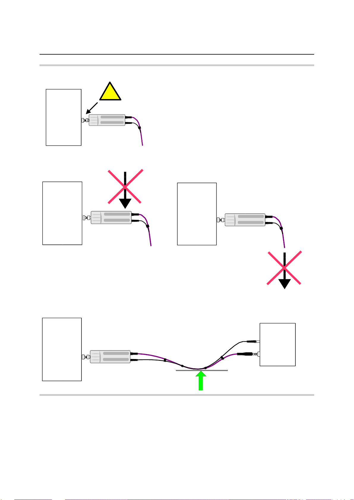
!!
Do not apply excessive mechanical force to the RF
connectors of the R&S NRP-Z27/-Z37 and DUT!
FF
FF
1169.3870.12 1.2 E-6
R&S NRP-Z27/-Z37 Connecting the sensor
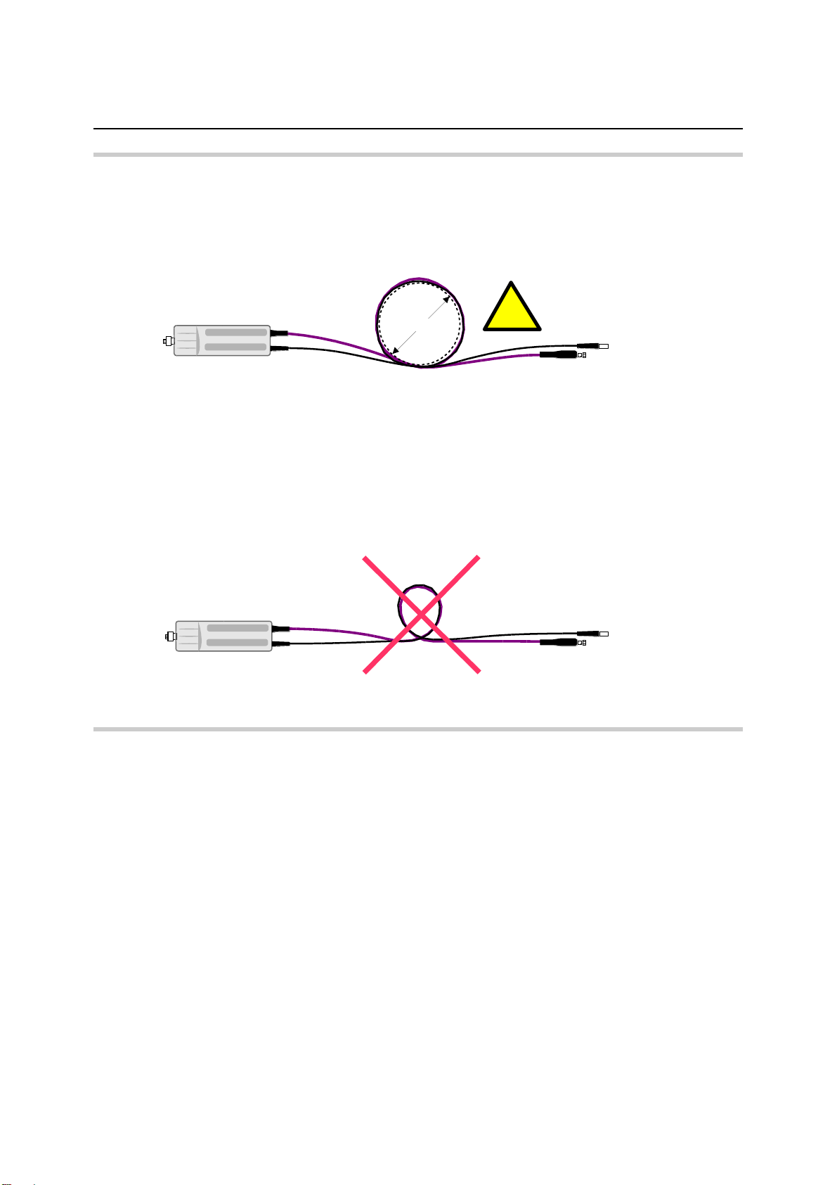
Make sure the bending radius of the RF connecting
cable is at least 75 mm!
> 150 mm
!!
A tighter bend can permanently impair the
measuring accuracy of the power measurement
module!
Operation with the Measuring Receiver R&S FSMR
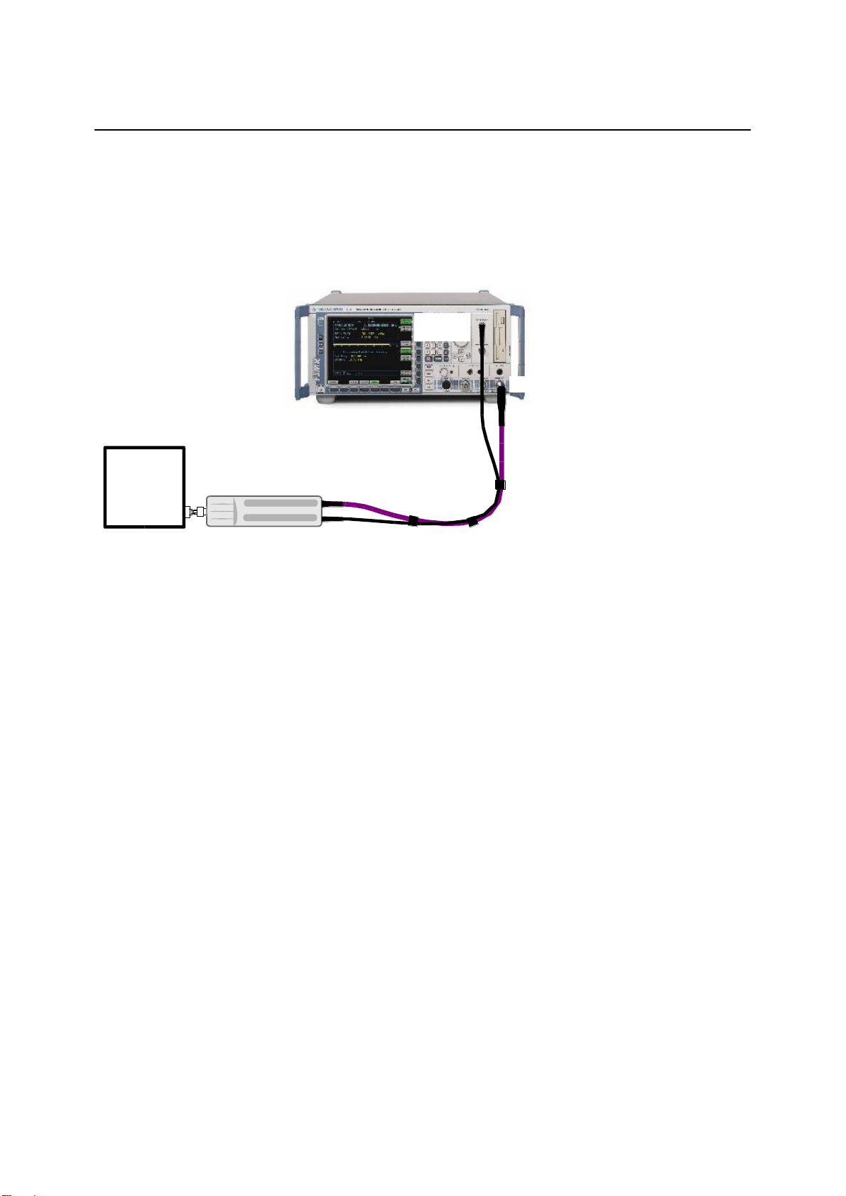
Connecting the power sensor module to the R&S FSMR
The power sensor module can be connected to the Measuring Receiver R&S FSMR when it is in
operation. The multiple circular plug-in connector must be inserted, red marking upwards, into the
POWER SENSOR connector. Then connect the 3.5 mm male connector of the RF cable with
measurement input RF INPUT 50 . If you are using model R&S FSMR26 or R&S FSMR50, you must
first install the appropriate test port adapter with 3.5 mm female connector (R&S 1021.0512.00). With
model R&S FSMR3, which has a built-in N-connector, screw on the adapter with the 3.5 mm female
connector and male N connector that is supplied. Only the use of these adapters ensures correct
functioning of the VSWR Correction function on the R&S FSMR.
1169.3870.12 1.3 E-6
Connecting the sensor R&S NRP-Z27/-Z37
R&S NRP-Z27/-Z37
R&S FSMR
POWER
SENSOR
RF INPUT
DUT
Connecting the power sensor module to the DUT
The power sensor modules have a male N connector (R&S NRP-Z27) or a male 3.5 mm connector
(R&S NRP-Z37) on their RF input and can thus be connected to any standard female N or
2.92 mm/3.5 mm/SMA connector, respectively. To connect the power sensor module to the DUT more
easily and without tilting it, relieve it by slightly lifting it.
Fig. 1-1 Configuration with the R&S FSMR
Performing measurements
The R&S FSMR handles the power sensors modules in a manner similar to the sensors of the
R&S NRP-Z series. To call up the power meter functionality, first press the PRESET key and then the
PWR METER softkey. For further details on operation, refer to the operating manual for the
R&S FSMR.
1169.3870.12 1.4 E-6
R&S NRP-Z27/-Z37 Connecting the sensor
R&S NRP-Z27/-Z37
R&S NRP/NRP2
Termination
SWR < 1.05
DUT
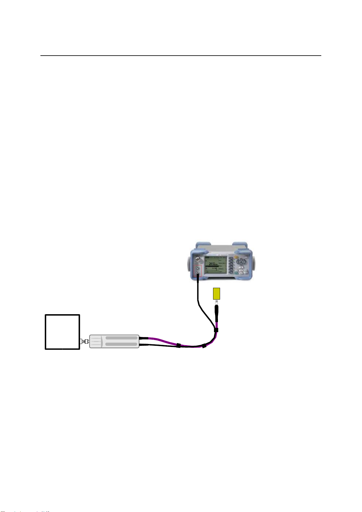
Operation with the Power Meter R&S NRP/NRP2
Connecting the power sensor module
The power sensor module can be connected to the R&S NRP/NRP2 base unit when it is in operation.
The multiple circular plug-in connector must be inserted, red marking upwards, into one of the
R&S NRP/NRP2 base unit’s sensor connectors. When the power sensor module is connected, it is
detected by the R&S NRP/NRP2 base unit and initialized.
Terminate the output of the RF cable with a 3.5 mm precision termination (with female connector input).
The exact matching value is insignificant as long as the standing wave ratio of the measurement
frequency remains smaller than 1.05. Otherwise, you have to check whether the increased
measurement uncertainty can be accepted (see the Isolation parameter in the specifications as well as
SENse:RGAMma group of commands in chapter 6).
Connecting the power sensor module to the DUT
The power sensor modules have a male N connector (R&S NRP-Z27) or a male 3.5 mm connector
(R&S NRP-Z37) on their RF input and can thus be connected to any standard female N or
2.92 mm/3.5 mm/SMA connector, respectively. To connect the power sensor module to the DUT more
easily and without tilting it, relieve it by slightly lifting it.
Fig. 1-2 Configuration with the R&S NRP
Performing measurements
The R&S NRP/NRP2 handles the power sensor modules in the same manner as the thermal power
sensors of the R&S NRP-Z5x series. An exception is the S-parameter correction function, which is
always activated in the power sensor modules. This function takes the integrated power splitter into
consideration. Therefore, the influence of adapters or attenuators which are connected ahead of the
input of the power sensor module cannot be compensated via the S-parameter correction function.
However, compensation by using a global offset or an offset table is always possible.
1169.3870.12 1.5 E-6

Connecting the sensor R&S NRP-Z27/-Z37
PC control
Hardware and software requirements
The following requirements must be met if the power sensor is to be controlled by a PC via an interface
adapter:
The PC must have a USB port.
Either Microsoft Windows XP (32 Bit), Microsoft Windows Vista (32 or 64 Bit), Microsoft Windows 7
(32 or 64 Bit), or x86 Linux (with kernel 2.6.8 oder more recent) must be installed as the operating
system of the PC. 64-bit versions of Microsoft Windows XP are not supported. Operation with older
versions of Microsoft Windows with USB support (especially Microsoft Windows 2000) is normally
possible but cannot be guaranteed.
The USB device drivers in the supplied NRP Toolkit software package must be installed.
If these requirements are met, the power sensor can be controlled using a suitable application program
such as the NrpFlashup program contained in the Microsoft Windows version of the NRP Toolkit
(includes the modules Power Viewer, USB Terminal, Firmware Update and Update S-Parameters).
When you insert the CD-ROM supplied with the R&S NRP, the NRP Toolkit is automatically installed on
your PC. The rest of the procedure is self-explanatory.
The power sensor can be powered in two ways:
Self-powered from a separate power supply via the Active USB Adapter R&S NRP-Z3 or the
Sensor Hub R&S NRP-Z5.
Bus-powered from the PC or a USB hub with its own power supply (self-powered hub) via the
Active USB Adapter R&S NRP-Z3 or via the Passive USB Adapter R&S NRP-Z4.
Because the power sensor R&S NRP-Z27/-Z37 has a maximum current capacity of 100 mA and is
therefore classified as a low-power device, it can be supplied with current from any stationary PC,
laptop or notebook in the bus-powered mode.
1169.3870.12 1.6 E-6

R&S NRP-Z27/-Z37 Connecting the sensor
Operation via the Passive USB Adapter R&S NRP-Z4
Fig. 1-3 is a schematic of the measurement setup. The order in which the cables are connected is not
critical.
Fig. 1-3 Configuration with Passive USB Adapter R&S NRP-Z4
Operation via the Active USB Adapter R&S NRP-Z3
Fig. 1-4 shows the configuration with the Active USB Adapter R&S NRP-Z3, which also makes it
possible to feed in a trigger signal for the Timeslot and Scope modes. The order in which the cables are
connected is not critical.
Fig. 1-4 Configuration with Active USB Adapter R&S NRP-Z3
The plug-in power supply for the R&S NRP-Z3 can be powered from a single-phase AC source with a
nominal voltage range of 100 V to 240 V and a nominal frequency between 50 Hz and 60 Hz. The plugin power supply autosets to the applied AC voltage. No manual voltage selection is required.
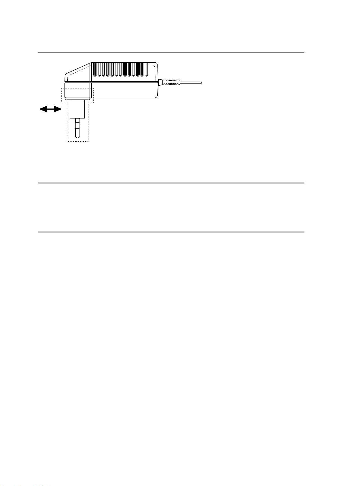
The plug-in power supply comes with four primary adapters for Europe, the UK, the USA and Australia.
No tools of any kind are required to change the primary adapter. The adapter is pulled out manually and
another adapter inserted until it locks (Fig. 1-5).
1169.3870.12 1.7 E-6
Connecting the sensor R&S NRP-Z27/-Z37
NOTICE
The plug-in power supply is not intended for outdoor use.
Keep within the temperature range of 0°C to 50°C.
If there is any condensation on the plug-in power supply, dry it off before connecting it to
the AC supply.
Fig. 1-5 Changing the primary adapter
The plug-in power supply is short-circuit-proof and has an internal fuse. It is not possible to replace this
fuse or open the plug-in power supply.
1169.3870.12 1.8 E-6

R&S NRP-Z27/-Z37 Connecting the sensor
NOTICE
The external power supply is not intended for outdoor use.
Keep within the temperature range of 0°C to 50°C.
If there is any condensation on the external power supply, dry it off before connecting it
to the AC supply.
Operation via the R&S NRP-Z5 Sensor Hub
The R&S NRP-Z5 sensor hub allows up to four power sensors to be operated on one PC. It combines
the following functions:
4-port USB 2.0 hub
Power supply
Through-wired trigger bus
Trigger input and trigger output via BNC sockets
Equipment Supplied and Alternative Accessories
The following equipment is supplied:
Sensor hub
External power supply
Power cable
USB cable
Instead of the supplied, 2 m long USB cable, it is possible to use any other USB-2.0-certified cable
(USB connector type A to USB connector type B) with a maximum length of 5 m. If a locking connection
is required at the instrument end, it is also possible to use the passive R&S NRP-Z4 interface adapter
instead of a standard USB cable.
As an alternative to the supplied external power supply, power can also be supplied using a DC voltage
source with an output voltage of 12 V to 24 V and a power output of at least 24 W. Make sure that the
polarity is correct (positive pole inside, negative pole outside). The alternative DC voltage source must
be in the same building as the R&S NRP-Z5 and must be connected to the latter via a cable with a
maximum length of 30 m. Power must not be supplied from a low-voltage supply system.
The supplied external power supply is short-circuit-proof and is also protected by an internal fuse. It is
not possible to change the fuse or open the unit.
1169.3870.12 1.9 E-6
Connecting the sensor R&S NRP-Z27/-Z37
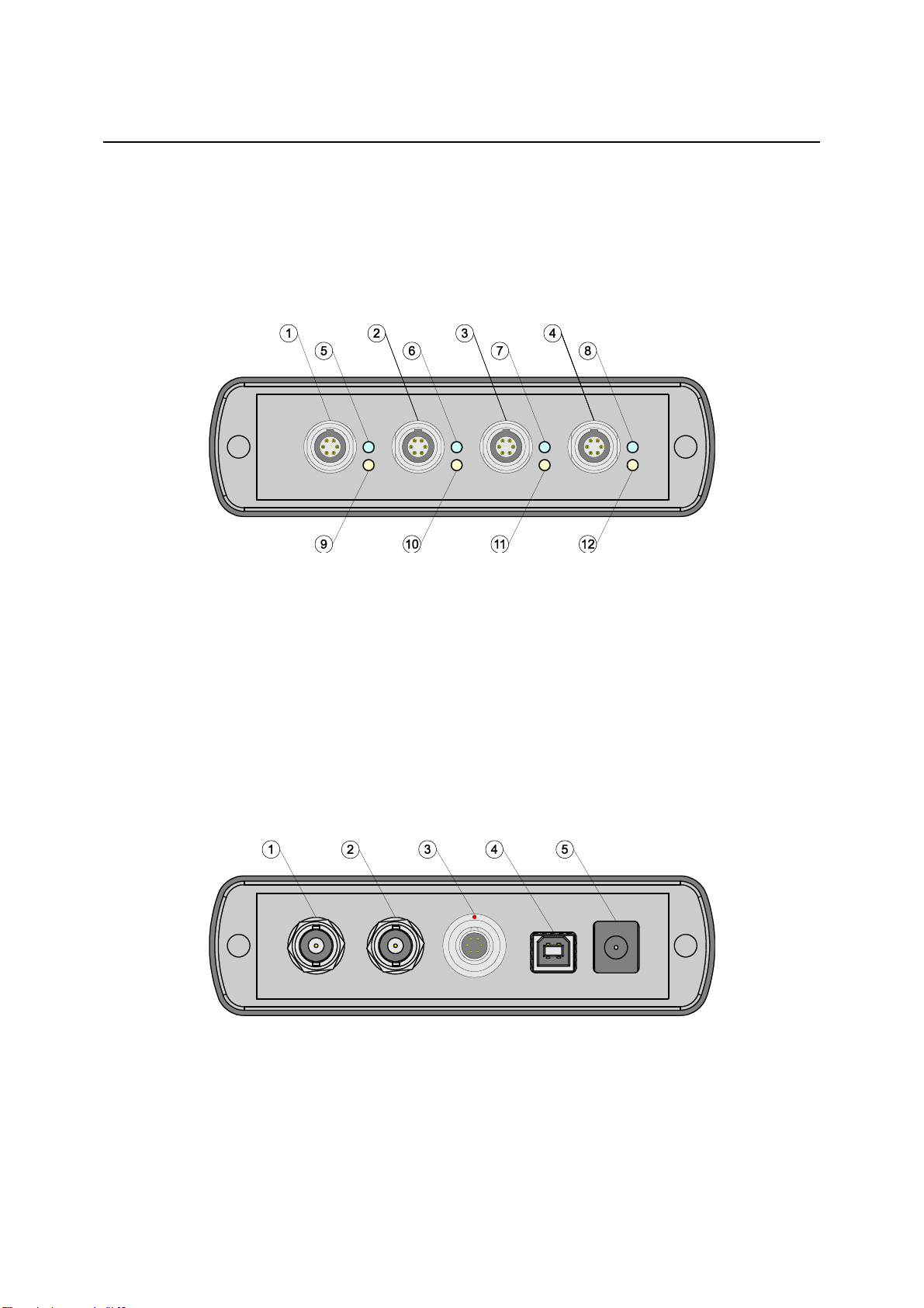
1–4
Sockets for connecting the power sensors
5–8
Green LEDs for indicating normal operation
9–12
Yellow LEDs for indicating faults
1
Trigger output (BNC socket)
2
Trigger input (BNC socket)
3
Plug allowing connection to Rohde & Schwarz measuring instruments (via R&S NRP-Z2) or to
a PC (via R&S NRP-Z4)
4
USB socket (type B) for connection to the USB host (PC or Rohde & Schwarz measuring
instrument without sensor socket)
5
Power supply socket (supplied external power supply unit or alternative power supply (12 V to
24 V/24 W))
Ports and LEDs
The power sensors are connected to the front panel of the R&S NRP-Z5. The ports and LEDs on the
front panel of the R&S NRP-Z5 are shown in Fig. 1-6.
Fig. 1-6 Ports and LEDs on front panel
On the rear panel are the ports for power supply, USB host, trigger input and trigger output. The ports
on the rear panel are shown in Fig. 1-7.
Fig. 1-7 Ports on rear panel
1169.3870.12 1.10 E-6
R&S NRP-Z27/-Z37 Connecting the sensor
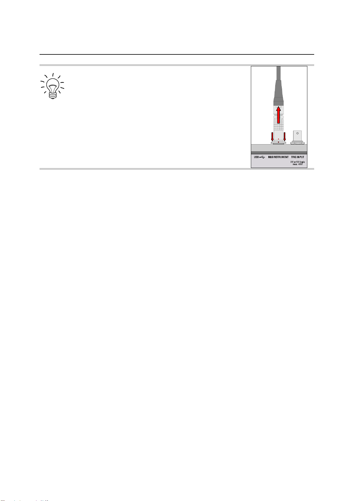
Unlatch the R&S Instrument connector on the rear panel by
pressing down the unlatching ring of the built-in
plug and pulling off the cable jack at the same
time (Fig. 1-8).
Fig. 1-8 Unlatching the R&S Instrument connector
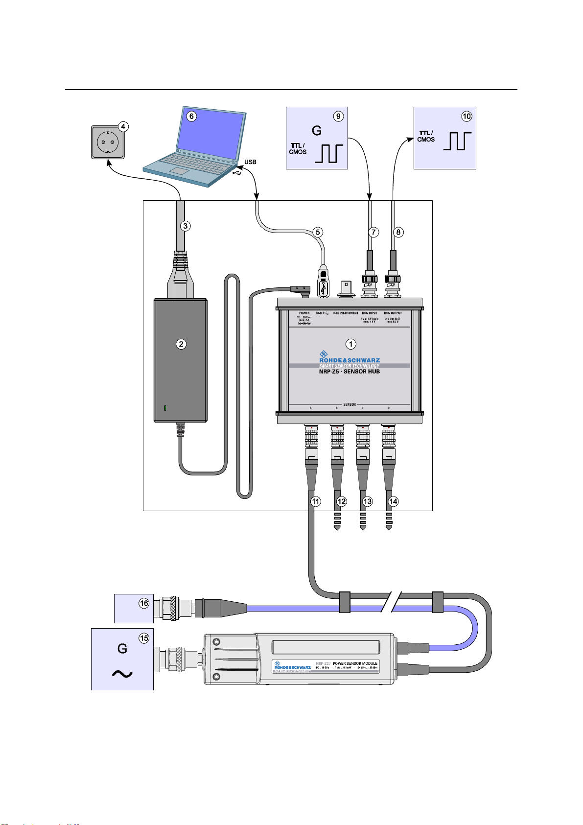
1
R&S NRP-Z5 sensor hub
2
External power supply unit (supplied)
3
Power cable (supplied)
4
AC power supply
5
USB cable (supplied)
6
PC with USB host port
7, 8
BNC cable (optional, not supplied)
9
Trigger source (optional)
10
Triggered device (optional)
11-14
R&S NRP-Zxx power sensors (one to four sensors)
15
Signal source
16
Termination (SWR < 1.05)
Test Setup
Fig. 1-9 shows a typical test setup:
The sequence in which the cables are connected is not important.
As already mentioned in section Ports and LEDs, the R&S NRP-Z4 passive interface adapter can also
be used as an alternative to a standard USB cable for connecting to the PC. This adapter is connected
to the R&S Instrument port. Simultaneous operation at two USB hosts is not possible as the USB host
connected to the R&S Instrument port always has priority.
It is possible to cascade several R&S NRP-Z5 sensor hubs by connecting the R&S Instrument port of
an R&S NRP-Z5 to one of the sensor ports of another R&S NRP-Z5. However, external triggering and
the use of the Trigger Master function are then not possible. Instead, it is recommended to connect all
R&S NRP-Z5 hubs individually to the USB host or to an interposed USB hub, and to feed the external
trigger signal to all R&S NRP-Z5 hubs via their trigger inputs; or to forward the external trigger signal
from the trigger output of the R&S NRP-Z5 to which the Trigger Master is connected to the trigger
inputs of the other R&S NRP-Z5 hubs.
1169.3870.12 1.11 E-6
Connecting the sensor R&S NRP-Z27/-Z37
Fig. 1-9 Typical test setup with R&S NRP-Z5 and PC
1169.3870.12 1.12 E-6
R&S NRP-Z27/-Z37 Connecting the sensor
Troubleshooting
A frequent problem, especially in the case of operation under Microsoft Windows XP, is that the
R&S NRP-Z5 fails to respond after a power sensor connected to the R&S NRP-Z5 is disconnected and
reconnected. It is then necessary to restart the PC.
This problem is not specific to the R&S NRP-Z5, but occurs with all USB hubs. You can try to eliminate
the problem by switching off the Selective Suspend for the USB port of the PC on which the R&S NRPZ5 is operated. The following step-by-step description is based on an English version of Windows XP:
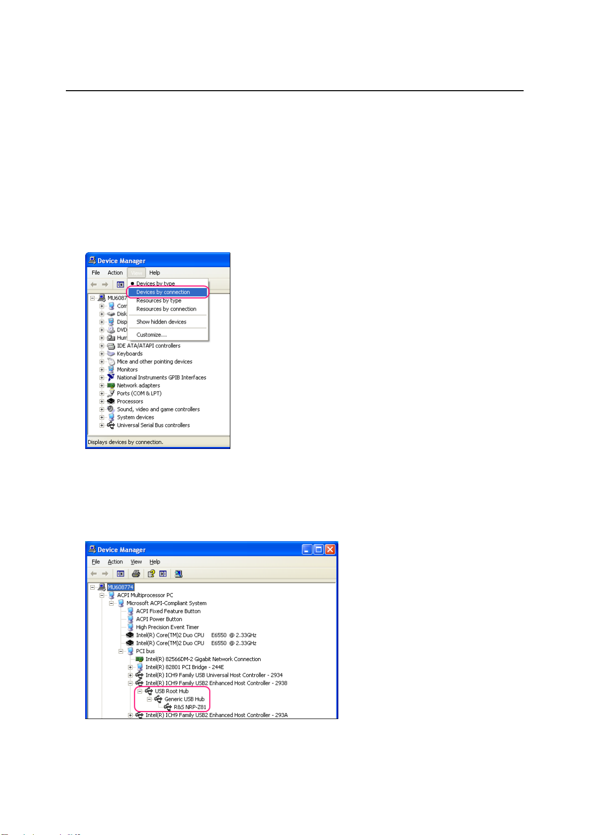
1. Connect the R&S NRP-Z5 and put it into operation. Connect at least one power sensor.
2. Start the Device Manager and change the view by selecting View - Devices by connection
(Fig. 1-10).
Fig. 1-10 Changing the view in Device Manager
3. Now identify the USB root hub on which the R&S NRP-Z5 is operated. To do so, expand the
hierarchical display of the PC components, as shown in Fig. 1-11. Under PCI bus, find the USB
host controller to whose root hub the R&S NRP-Z5 is connected. The R&S NRP-Z5 is shown as the
Generic USB Hub. It can be distinguished from other USB hubs by the power sensor connected to
it.
Fig. 1-11 Identification of USB root hub on which R&S NRP-Z5 is operated
1169.3870.12 1.13 E-6
Connecting the sensor R&S NRP-Z27/-Z37
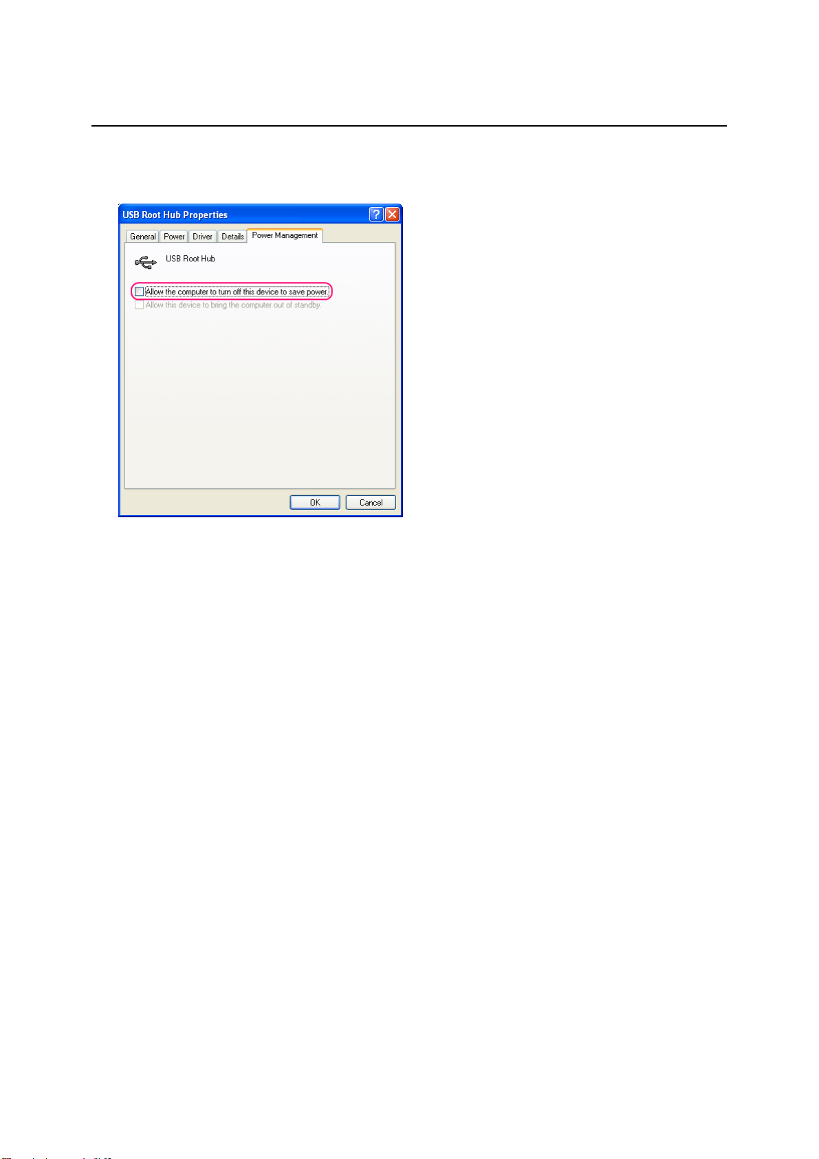
4. Double-clicking USB Root Hub opens the USB Root Hub Properties dialog box. Select the Power
Management tab. Remove the check mark next to Allow the computer to turn off this device to
save power and confirm this with OK.
Fig. 1-12 Deactivation of Selective Suspend for a USB root hub
Connecting the sensor to the DUT
The power sensor modules have a male N connector (R&S NRP-Z27) or a male 3.5 mm connector
(R&S NRP-Z37) on their RF input and can thus be connected to any standard female N or
2.92 mm/3.5 mm/SMA connector, respectively. To connect the power sensor module to the DUT more
easily and without tilting it, relieve it by slightly lifting it.
Performing measurements
The R&S NRP uses the power sensor modules in the same manner as the thermal power sensors of
the R&S NRP-Z5x series. An exception is the S-parameter correction function, which is always
activated in the power sensor modules. This function takes the integrated power splitter into
consideration. Therefore, the influence of adapters or attenuators which are connected ahead of the
input of the power sensor module cannot be compensated via the S-parameter correction function.
However, compensation by using a global offset or an offset table is always possible.
1169.3870.12 1.14 E-6

R&S NRP-Z27/-Z37 Connecting the sensor
Operation with other Rohde & Schwarz test instruments
Hardware and software requirements
Many Rohde & Schwarz test instruments allow power measurements using power sensors of the
R&S NRP-Zxx series. The power sensors are generally connected to the USB ports of the test
instrument via one of the two interface adapters, R&S NRP-Z3 or R&S NRP-Z4, or the Sensor Hub
R&S NRP-Z5. On some instruments, such as the R&S SMU signal generator, there is also an
R&S NRP sensor connector available for a direct connection. The R&S NRP-Z5 can be hooked up to
this connector via an extension cable R&S NRP-Z2 (Model .03, .05, or .15). For that purpose, the
R&S Instrument connector of the R&S NRP-Z5 is used.
1169.3870.12 1.15 E-6
 Loading...