


R&S®NRPV
Virtual Power Meter
User Manual
(;×3>2)
1173031402
User Manual
Version 07

This document describes the R&S®NRPV Virtual Power Meter Software, stock no. 1173.0314.02.
© 2019 Rohde & Schwarz GmbH & Co. KG
Mühldorfstr. 15, 81671 München, Germany
Phone: +49 89 41 29 - 0
Fax: +49 89 41 29 12 164
Email: info@rohde-schwarz.com
Internet: www.rohde-schwarz.com
Subject to change – Data without tolerance limits is not binding.
R&S® is a registered trademark of Rohde & Schwarz GmbH & Co. KG.
Trade names are trademarks of the owners.
1173.0314.02 | Version 07 | R&S®NRPV
Throughout this manual, products from Rohde & Schwarz are indicated without the ® symbol, e.g. R&S®NRPV is indicated as
R&S NRPV.

R&S®NRPV
Contents
Contents
1 Preface.................................................................................................... 5
2
Welcome to R&S®NRPV.........................................................................7
3 System Setup......................................................................................... 9
4 Quick Start Guide.................................................................................24
5 Operating Concept...............................................................................47
6 Settings - GUI Reference.....................................................................69
7 Appendix.............................................................................................171
Index....................................................................................................173
3User Manual 1173.0314.02 ─ 07

R&S®NRPV
Contents
4User Manual 1173.0314.02 ─ 07

R&S®NRPV
1.1.1 User Manual and Help
Preface
Documentation Overview
1 Preface
1.1 Documentation Overview
This section provides an overview of the R&S NRPV user documentation. Unless
specified otherwise, you find the documents on the R&S NRPV product page at:
www.rohde-schwarz.com/manual/nrpv
Introduces the R&S NRPV and describes how to set up and start working with the
product. Includes basic operations and measurement examples. Contains also the
description of all application modes and functions.
The contents of the user manuals are available as help in the R&S NRPV. The help
offers quick, context-sensitive access to the complete information for the base unit and
the software options.
The user manual is also available for download or for immediate display on the Internet.
1.1.2 Data Sheets and Brochures
The data sheet contains the technical specifications of the R&S NRPV. It also lists the
options and their order numbers, and optional accessories.
The brochure provides an overview of the instrument and deals with the specific characteristics.
See www.rohde-schwarz.com/brochure-datasheet/nrpv
1.1.3 Release Notes and Open Source Acknowledgment (OSA)
The release notes list new features, improvements and known issues of the current
firmware version, and describe the firmware installation.
The open source acknowledgment document provides verbatim license texts of the
used open source software.
See www.rohde-schwarz.com/software/nrpv
1.1.4 Application Notes, Application Cards, White Papers, etc.
These documents deal with special applications or background information on particular topics.
5User Manual 1173.0314.02 ─ 07
R&S®NRPV
See www.rohde-schwarz.com/application/nrpv
1.2 About this Manual
This User Manual describes general functions, the operation and all settings of the
application.
The following topics are included:
●
Chapter 2, "Welcome to R&S®NRPV...", on page 7 introduces to the virtual
power meter software R&S NRPV.
●
Chapter 3, "System Setup", on page 9 provides information required to prepare
the application for power measurement. The chapter covers soft- and hardware
requirements, describes how to install the software on a computer and how to get
the application started.
●
Chapter 4, "Quick Start Guide", on page 24 covers a short description of the
application and some basic information about power measurement. To quickly get
started, a step-by step procedure describes how to perform a continuous average
measurement.
●
Chapter 5, "Operating Concept", on page 47 introduces the operating concept
with the basic components of the graphical user interface and how to operate.
●
Chapter 6, "Settings - GUI Reference", on page 69 describes menus and func-
tions of the application in detail.
●
Chapter 7, "Appendix", on page 171 provides an index and makes familiar with the
conventions used in this manual. It covers information on warning messages and
R&S information for customer support and service.
Preface
Typographical Conventions
1.3 Typographical Conventions
The following text markers are used throughout this documentation:
Convention Description
"Graphical user interface elements"
[Keys] Key and knob names are enclosed by square brackets.
Filenames, commands,
program code
Input Input to be entered by the user is displayed in italics.
Links Links that you can click are displayed in blue font.
"References" References to other parts of the documentation are enclosed by quota-
All names of graphical user interface elements on the screen, such as
dialog boxes, menus, options, buttons, and softkeys are enclosed by
quotation marks.
Filenames, commands, coding samples and screen output are distinguished by their font.
tion marks.
6User Manual 1173.0314.02 ─ 07

R&S®NRPV
Welcome to R&S®NRPV...
Main Features
2
Welcome to R&S
… the power meter software application for R&S Instruments
This chapter gives an introduction to the Virtual Power Meter, including main features,
scope and system overview.
2.1 Introduction
The power meter software application R&S NRPV represents power measurement for
the most relevant frequency bands and power classes. By communicating with R&S
NRP-Zxx and R&S NRPxxS(N) sensors the program covers a wide range of applications. Besides the basic continuous average measurement function, R&S NRPV also
includes the measurement modes timeslot, burst and scope measurement.
The R&S NRP-Zxx and the R&S NRPxxS(N) are highly accurate standalone measuring instruments. With their internal CPU the power sensors process the measurement
results and communicate directly with a PC via an USB connection. Additionally, the
R&S NRPxxSN, the so called network sensors, are equipped with a Gigabit Ethernet
interface with Power-over-Ethernet (PoE) power supply.
With a high dynamic range and automatic error correction the power sensors are suitable for nearly every measurement task. As an example, among other duties, the NRPZ81 is able to measure pulse parameters automatically, and the R&S NRPV software
represents the results.
®
NRPV...
For measurements with any number of power sensors the graphical user interface of
R&S NRPV offers functionality and operation comparable to a multi-channel oscilloscope.
2.2 Main Features
R&S NRPV supports all sensor features and settings in the following measurement
modes:
●
Trace measurement for representing signal power in the time domain. If you are
working with an NRP-Z8x power sensor, for example, the R&S NRPV also supports
pulse analysis.
●
Numerical measurement modes as:
– Continuous mode to measure the average power of continuous signals
– Burst mode to analyze pulsed signals. R&S NRPV automatically recognizes
the start and end of a burst. It is possible to exclude pulse build up and decay
phases, for example to omit signal overshoots.
– Timeslot mode to display the values in a defined time segment. The start and
stop of a pulse signal can be excluded optionally, for example to fade out slow
7User Manual 1173.0314.02 ─ 07

R&S®NRPV
edges. It is also possible to exclude time domains during measurements, for
example if power fails in certain ranges.
– Gates mode to exclude time segments during measurement
– Statistics measurements to evaluate the ratio of the signal density/distribution
versus power
You can view the measurement results directly, or represent ratios of various traces,
and even record and store measurements over a long term. R&S NRPV indicates the
measurement results numerically as well as graphically.
In addition, you can setup several measurements in parallel. While a measurement is
active, the others are in standby state, and you can quickly and easily switch between
them.
2.3 Scope of Applications
The R&S NRPV covers apart from other functions the following fields of application:
●
Test setups and procedures for power amplifiers
●
Measurement of the frequency and/or level response
●
Fast measurement of the transmission characteristics of filters, amplifiers and
frequency converters over a large frequency and dynamic range
●
Measurement of radar systems and their components
●
Measurements compliant with major communication base station standards such
as GSM, WCDMA, etc.
Welcome to R&S®NRPV...
Scope of Applications
8User Manual 1173.0314.02 ─ 07
R&S®NRPV
System Setup
Hardware
3 System Setup
System setup provides information required to prepare the application for power measurement. The chapter contains soft- and hardware requirements, describes how to
install the software on a personal computer and how to get started.
The Virtual Power Meter is provided free of charge on the internet at the download site
of Rohde & Schwarz:
http://www.rohde-schwarz.com/product/NRPV.html
For using the R&S NRPV with the R&S NRPxxS(N) no license key is needed. You can
use the R&S NRPV and all its functions for free.
Power measurements with an R&S NRP-Zxx series power sensor are activated by purchasing a license key for each sensor.
Contact the R&S sales department for purchase. The license key comes with an
instruction to activate the power sensor in the Virtual Power Meter.
3.1 Hardware
For controlling the sensors by a PC the following hardware prerequisites must be fulfilled
Table 3-1: Hardware requirements
CPU Pentium IV 1 GHz or higher
RAM 1 Gbyte
Hard disk 50 Mbyte free space
Monitor XGA monitor (1024 x 768)
Interfaces USB 1.1 or USB 2.0
3.1.1 Accessories (optionally)
●
High-speed hubs for USB 2.0 with own power supply for connecting several power
sensors. For information on recommended USB hubs refer to Chapter 3.4.3, "R&S
NRP-Zxx Multiple Measurement Setup", on page 15
●
NRP-Z3, active USB adapter cable 3 (only for R&S NRP-Zxx Power Sensors)
Supports applications that require external triggering of the power sensor, and provides separate power supply.
●
NRP-Z4, passive USB adapter cable (only for R&S NRP-Zxx Power Sensors)
Supports all basic functions of the sensors like transmission of settings, measurement data and provides power supply of the sensor via the USB bus.
●
NRP-Z2, extension cable (only for R&S NRP-Zxx Power Sensors)
Minimum requirement
9User Manual 1173.0314.02 ─ 07

R&S®NRPV
System Setup
Cables of various lengths support test setups with distant sources of up to 10
meters.
●
NRP-Z5, 4 port USB hub adapter box
The NRP-Z5 Sensor Hub covers a high-speed USB 2.0 hub. This sensor hub
allows to connect up to four R&S NRP-Zxx Power Sensors, and supports various
trigger modes, such as:
– bidirectional triggering from a host, like a PC or an R&S instrument
– internal triggering
– external synchronous triggering
– triggering in master mode together with the NRP-Z8x sensors.
Connection to a sensor is possible with the USB adapter cable NRP-Z4 and with
cable extension NRP-Z2.
The NRP-Z5 can be connected to a PC either with the NRP-Z4 adapter cable, or
with a standard USB cable. Separate power supply is not required.
●
NRP-ZKU cable with a USB connector (only for R&S NRPxxS(N))
Cables of various lengths for connecting the R&S NRPxxS(N) power sensors to
USB devices.
●
NRP-ZK6 cable with a push-pull type connector (only for R&S NRPxxS(N))
Cables of various lengths for connecting the R&S NRPxxS(N) power sensors to
supported Rohde & Schwarz instruments.
Software
3.2 Software
The Virtual Power Meter software runs on PCs with Microsoft®Windows operating system.
R&S NRPV is available free of charge. You can find the program file
NRPV_SetupV1.x.y.exe
for download on the Rohde & Schwarz website:
http://www.rohde-schwarz.com/product/NRPV.html
x and y are sub-version and build numbers.
3.2.1 R&S NRPV Software Components
The setup program contains all components required for installation and operation of
the R&S NRPV.
●
RS_NRPV.exe the executable application file
●
ReleaseNotes.txt with up-to date notes on the individual components and software versions.
●
Microsoft® Runtime vcredist_x86.exe
10User Manual 1173.0314.02 ─ 07
R&S®NRPV
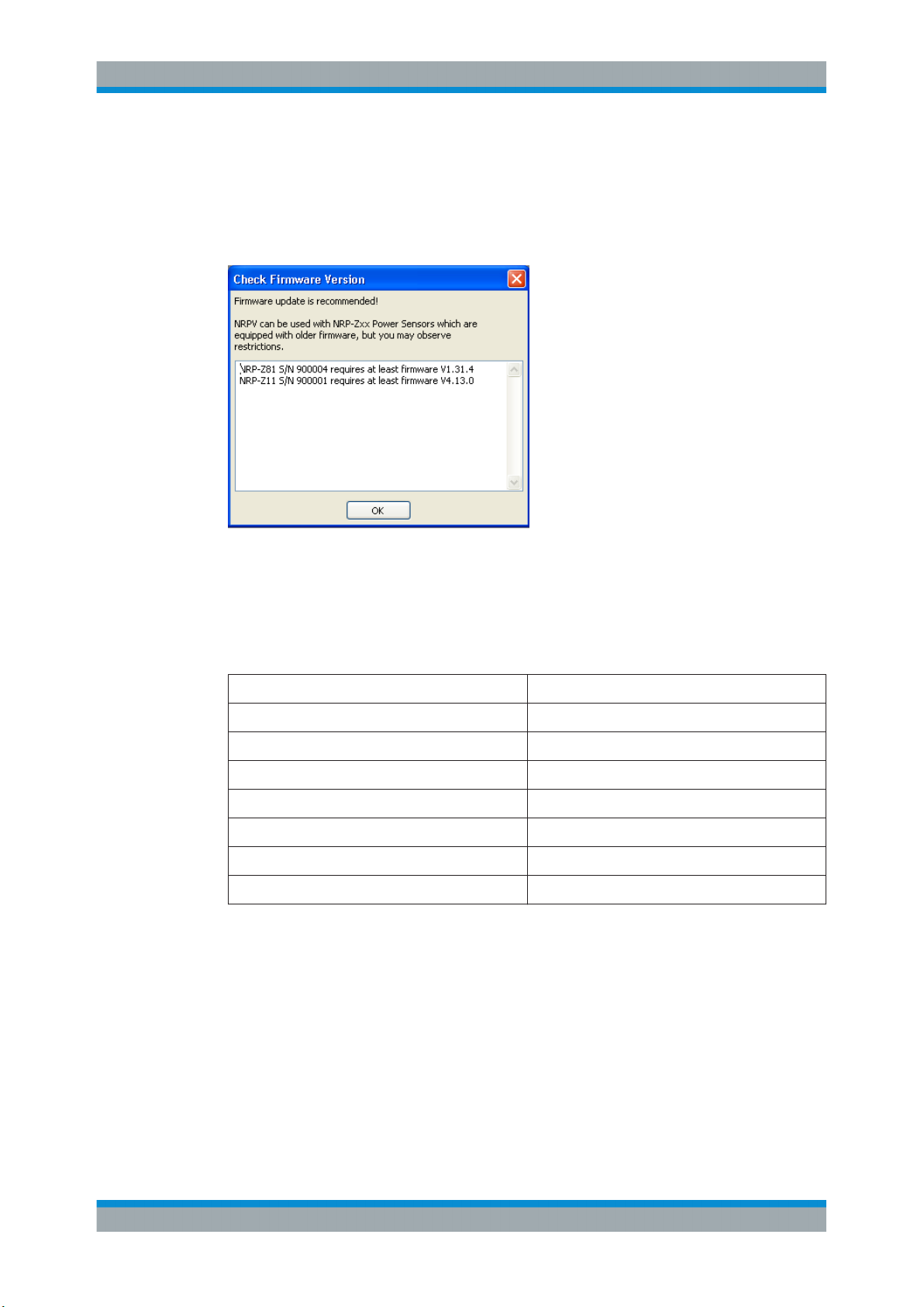
3.2.2 Power Sensors Firmware
System Setup
Installing R&S NRPV Virtual Power Meter Software
Since R&S NRPV works closely leant on the functionality of the power sensors, the
program checks the firmware version of every connected sensor, and returns a list of
the sensors that require a firmware update.
To update the sensor firmware, use the R&S NRP-Toolkit. You find the latest firmware
version in the download area of the R&S website:
http://www.rohde-schwarz.com/en/product/nrpz.html
http://www.rohde-schwarz.com/en/product/nrp_s_sn.html
Table 3-2: Required firmware versions
NRP-Z1x V4.13 or later
NRP-Z2x V4.13 or later
NRP-Z3x V4.13 or later
NRP-Z5x V4.13 or later
NRP-Z8x V1.31.04 or later
NRP-Z9x V4.13 or later
NRPxxS/ NRPxxSN V14.12 or later
Minimum
3.3 Installing R&S NRPV Virtual Power Meter Software
This section describes the installation of the R&S NRPV software on a Microsoft®Windows based PC. Additionally, the section contains information on the software packages, prerequisites and uninstalling.
11User Manual 1173.0314.02 ─ 07
R&S®NRPV
3.3.1 Installing R&S NRPV
System Setup
Installing R&S NRPV Virtual Power Meter Software
Prerequisites
●
Use the latest version of the R&S NRPV software. It is provided at the R&S website
http://www.rohde-schwarz.com/product/NRPV.html.
●
Close all running applications before installing.
R&S NRPV requires at least 50 MB of free disk space.
1. Download the latest version of the R&S NRPV setup program from the R&S web-
site http://www.rohde-schwarz.com/product/NRPV.html.
2. Execute NRPV_SetupV1.x.y.exe, and follow the instructions of the setup wizard.
During installation, the setup program:
●
Installs the "Microsoft VC Runtime libraries", which may take some time
●
Provides selection of the destination directories for the R&S NRPV application files
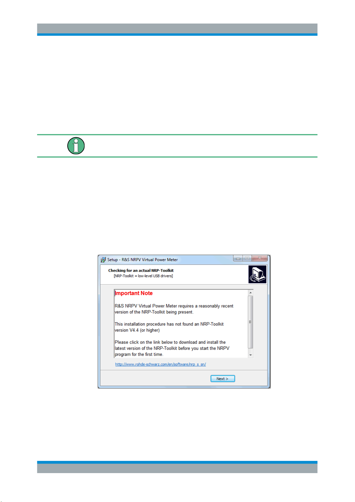
●
Checks whether a current version of the NRP-Toolkit is installed on the computer. If
this is not the case a message will appear:
The NRP-Toolkit can be downloaded for free on the R&S website:
http://www.rohde-schwarz.com/en/software/nrp_s_sn/
12User Manual 1173.0314.02 ─ 07
R&S®NRPV
3.3.2 Uninstalling R&S NRPV
System Setup
Connecting an R&S Power Sensor to the PC
Uninstall a version of R&S NRPV with the aid of the PC´s control panel:
1. In the Windows task bar, "Start > Settings > Control Panel"
2. Select "Add or Remove Programs".
3. In the dialog, select Virtual Power Meter V1.x.y (x.y. represents the version).
4. To uninstall the program, select "Uninstall".
3.4 Connecting an R&S Power Sensor to the PC
This section shows some basic test setups and the cabling.
Putting the Power Sensors into Operation
●
Functions and features your power sensors are described in the corresponding
operating manual of the sensor, included in delivery.
●
To prevent damage to the sensor, follow closely the instructions, how to put the
sensor into operation.
●
Make sure that all sensors are connected to the PC (either directly or via USB
hubs) when starting R&S NRPV. For Information on how to check that a power
sensor is working properly see Chapter 3.7.2, "Check if a power sensor is working
properly", on page 22
If an R&S NRP-Zxx Power Sensors is being connected to the PC the first time, the
application installs the USB driver for the sensor automatically. USB drivers for the
power sensors are provided with the R&S NRP-Toolkit.
3.4.1 Connecting the R&S NRPxxS(N) to a PC
There are different ways for connecting the R&S NRPxxS(N) power sensors to a PC.
For a description of this setups refer to the user manual of your sensor.
13User Manual 1173.0314.02 ─ 07
R&S®NRPV
3.4.2 R&S NRP-Zxx Single Measurement Setup
System Setup
Connecting an R&S Power Sensor to the PC
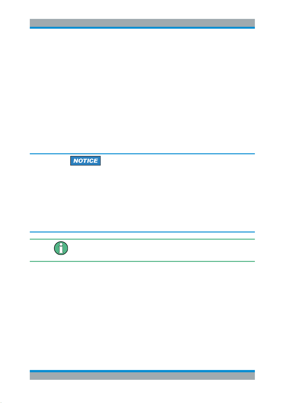
Figure 3-1: Measurement setup with a passive adapter cable NRP-Z4
Figure 3-2: Measurement setup with an active adapter cable NRP-Z3
1. Connect the R&S NRP-Zxx Power Sensors with the USB port of the PC using the
NRP-Z3 or NRP-Z4 adapter cables.
2. Connect the signal source (DUT - Device Under Test) and the power sensor.
14User Manual 1173.0314.02 ─ 07
R&S®NRPV
3.4.3 R&S NRP-Zxx Multiple Measurement Setup
System Setup
Connecting an R&S Power Sensor to the PC
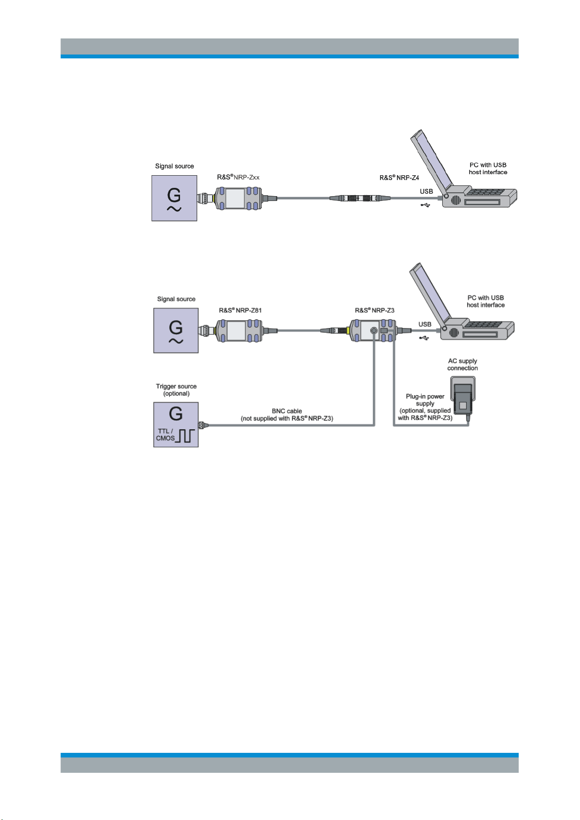
Figure 3-3: Multiple measurement setup with a USB 2.0 hub
If an application works with more than one R&S NRP-Zxx Power Sensors, you probably need a USB hub. It is recommended that you use an NRP-Z5 Sensor Hub which
perfectly fits to R&S power sensors.
1. Connect the R&S NRP-Zxx Power Sensors and the USB hub using the NRP-Z3 or
NRP-Z4 adapter cables
2. Connect the USB hub's upstream port with a USB port of the PC.
3. Connect the signal sources and the power sensors
The following section provides additional information related to the USB interface and
information on operating multiple sensors simultaneously.
Multiple Sensors
If multiple sensors need to be connected to one computer, make sure that the USB
device can provide the required amount of current for all sensors. A sensor may need
between 300 mA and 500 mA.
Example:
The NRP-Z81 sensor needs up to 500 mA supply current. Using 4 sensors simultaneously on one USB hub requires a total current of at least 2 Amperes.
Even if the rated current values are given in the data sheets, commercially available
USB hubs often do not reliably provide this amount of supply current over a long period
of time.
15User Manual 1173.0314.02 ─ 07
R&S®NRPV
3.4.4 R&S NRP-Zxx Complex Measurement Setup
System Setup
Connecting an R&S Power Sensor to the PC
It is recommended that you use the NRP-Z5 sensor hub, a 4 port USB hub adapter
box, which perfectly fits to R&S NRP-Zxx Power Sensors.
Otherwise, for industrial-grade applications USB hubs for DIN rail mount can provide
up to 1 Ampere per USB port and run off a 24 V power supply.
The following manufacturers provide such devices:
●
Beckhoff http://www.beckhoff.com CU8005
●
Luetze http://www.luetze.de 745581 DIOHUB USB 4
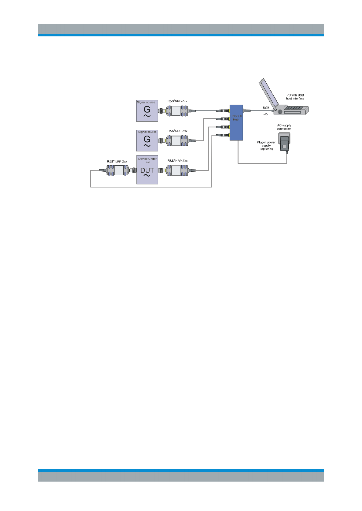
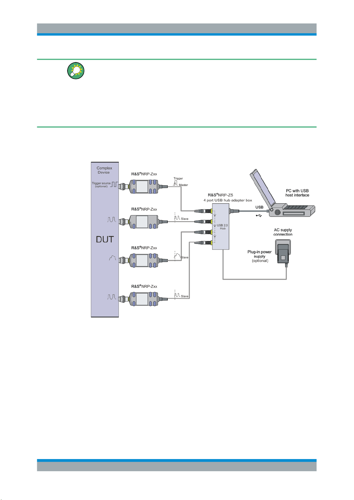
Figure 3-4: Complex measurement setup with a 4 port USB hub adapter box NRP-Z5
1. Connect the plug in power supply
2. Connect the external trigger source
3. Connect the R&S NRP-Zxx Power Sensors and the USB hub using the NRP-Z3 or
NRP-Z4 adapter cables
4. Connect the signal sources and the power sensors
16User Manual 1173.0314.02 ─ 07
R&S®NRPV
3.5 Starting the R&S NRPV Software
License required
For using the R&S NRPV with the R&S NRPxxS(N) no license key is needed. You can
use the R&S NRPV and all its functions for free.
Power measurement with R&S NRP-Zxx Power Sensors and R&S NRPV requires a
license key for activating the sensor. Contact the R&S sales department for purchase.
If you have already purchased license(s), refer to Chapter 3.6.1, "Activating with
License", on page 19 for activating your sensor in the R&S NRPV.
If a sensor is connected without a license, you can activate the sensor temporarily, for
example, to explore the functionality of the software. See Chapter 3.6.2, "Activating
without License for Temporary Use", on page 20.
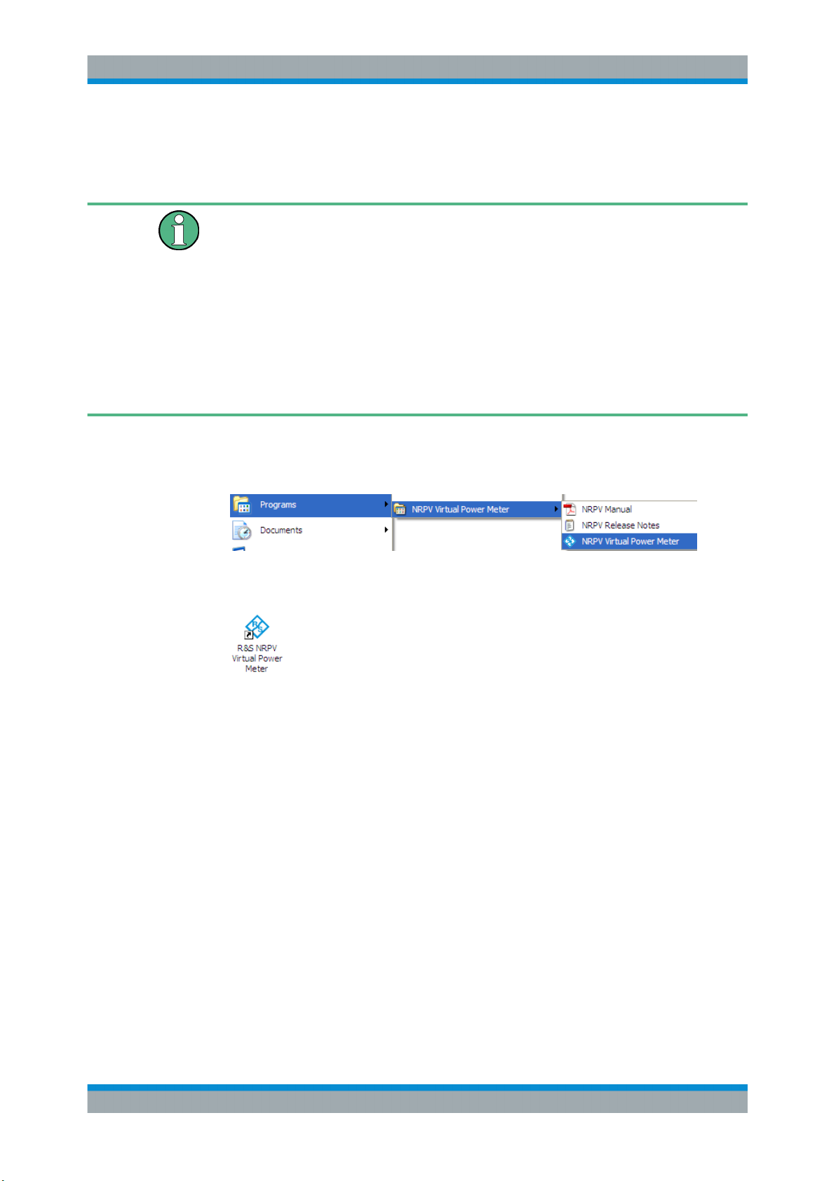
To start the R&S NRPV perform one of the following:
●
In the Windows taskbar, select "Start > Programs > NRPV Virtual Power Meter >
NRPV Virtual Power Meter"
System Setup
Starting the R&S NRPV Software
Figure 3-5: Start R&S NRPV
●
On the desktop, select the "R&S NRPV" icon.
Figure 3-6: R&S NRPV Desktop icon
The icon has been automatically created during installation.
●
In the Windows Explorer, select
%PROGRAMFILES%\Rohde-Schwarz\RS_NRPV.exe, where %PROGRAMFILES%
is a system variable and refers to the directory, programs are installed in.
Immediately after turning on the start screen appears until the application is ready for
operation. The application opens in a specific preset configuration, see Chapter 6.2.2,
"Startup Configuration", on page 73.
17User Manual 1173.0314.02 ─ 07
R&S®NRPV
System Setup
Activate an R&S NRP-Zxx Power Sensors in R&S
NRPV
Figure 3-7: Startup Screen
R&S NRPV Startup Configuration
In this dialog you can select the following startup configuration:
●
The last active state
●
A user definable mode, specified in a task file.
●
Default settings
3.6 Activate an R&S NRP-Zxx Power Sensors in
R&S NRPV
While the R&S NRPxxS(N) series of USB power sensors contain an activation key for
the NRPV as a factory default, the R&S NRP-Zxx series power sensors need to be
activated for the use with NRPV.
If you have already purchased a license key for your R&S NRP-Zxx sensor, proceed as
described in the following section. Alternatively, you can activate a sensor without a
license temporarily, to explore the functionality and scope of the Virtual Power Meter.
18User Manual 1173.0314.02 ─ 07
R&S®NRPV
3.6.1 Activating with License
System Setup
Activate an R&S NRP-Zxx Power Sensors in R&S NRPV
In the delivery you find a license key that unlocks your NRP-Zxx sensor in the
R&S NRPV. If you want to perform tasks with several power-sensors, you need a
license key for each sensor.
To activate the sensor, proceed as follows:
1. Start R&S NRPV and first connect the sensor.
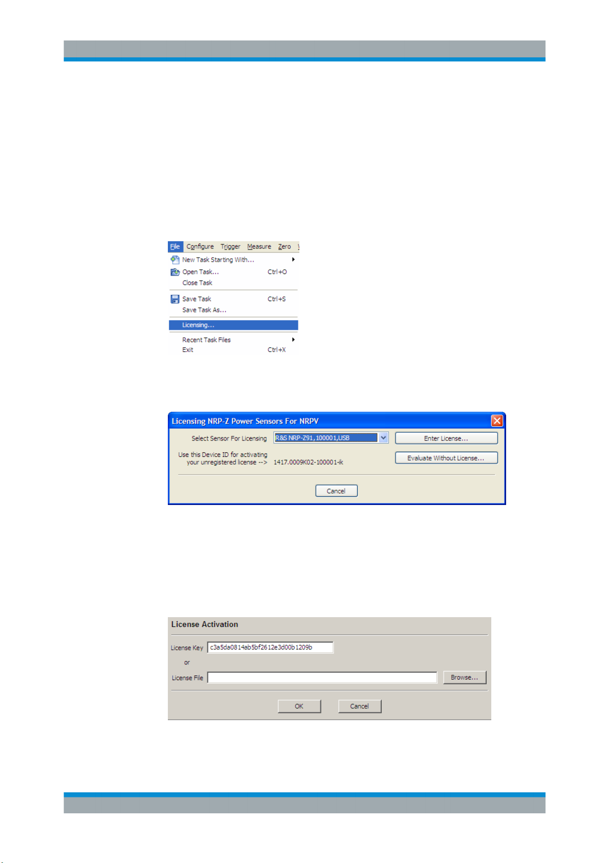
2. In the "File" menu, select "File > Licensing"
Figure 3-8: File > Sensor licensing
The "Licensing NRP-Z Power Sensors for NRPV" dialog opens.
Figure 3-9: Licensing NRP-Z Power Sensor for R&S
NRPV
The dialog indicates all currently connected sensors for selection.
3. Select the sensor.
4. Select "Enter License".
The "License Activation" dialog opens.
Figure 3-10: License Activation
19User Manual 1173.0314.02 ─ 07

R&S®NRPV
System Setup
Activate an R&S NRP-Zxx Power Sensors in R&S
NRPV
5. Enter the license key either manually or with the key code file.
6. Confirm with "OK" to return to the "Licensing NRP-Z Power Sensors for NRPV" dialog.
Figure 3-11: Licensing NRP-Z Power Sensor for R&S NRPV > completed
Are there still sensors listed, repeat the process for each one, provided you have
the appropriate number of licenses.
The "<No unknown sensor found>" message confirms that no unlicensed sensor is
connected.
All sensors are enabled and ready for operation with R&S NRPV
3.6.2 Activating without License for Temporary Use
If you want to evaluate the R&S NRPV before buying a license for your R&S NRP-Zxx
Power Sensors:
1. In the "File" menu, select "File > Licensing"
The "Licensing NRP-Z Power Sensors for NRPV" dialog opens.
2. Select "Evaluate Without License…"
Figure 3-12: Licensing NRP-Z Power Sensor for R&S
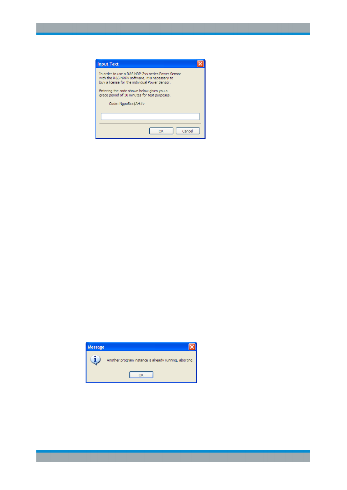
The "Input Text" dialog opens and displays a code sequence for activation.
NRPV > evaluate without license
20User Manual 1173.0314.02 ─ 07
R&S®NRPV
System Setup
Troubleshooting for Setup Related Problems
Figure 3-13: Licensing NRP-Z Power Sensor for R&S NRPV > code without license
The code is generated randomly and changes with each new call.
3. Enter the displayed "Code" string exactly as shown in the "Input Text" dialog box.
The coding is case sensitive.
4. Confirm with ok.
This function activates your power sensor for a period of time.
Power sensors which are enabled temporarily show a thin red bar beneath their
icon in the program’s status bar. The length of this bar decreases until the evaluation period is expired.
3.7 Troubleshooting for Setup Related Problems
This chapter contains information to possibly arising problems concerning restrictions,
the USB interface or if several sensors are attached.
3.7.1 Known Restrictions
Only one instance of R&S NRPV can run at a time, multiple program invocation is not
supported. At program start, a test routine checks if any other instance is already running. If the program is started twice, a warning message appears.
Figure 3-14: Single instance warning
A simultaneous operation of R&S NRPV with other software using the R&S power sensors (for example R&S Power Viewer Plus) is also not supported.
21User Manual 1173.0314.02 ─ 07
R&S®NRPV
3.7.2 Check if a power sensor is working properly
System Setup
Troubleshooting for Setup Related Problems
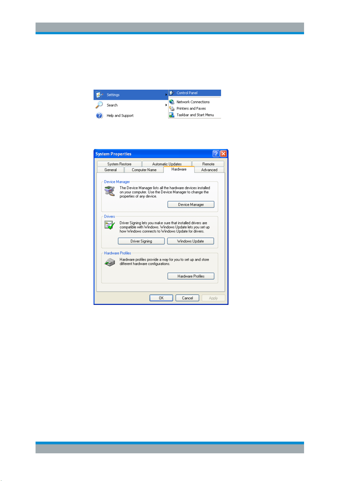
1. On the desktop, select "Start > Settings > Control Panel".
Figure 3-15: Settings > Control Panel
2. Select the "System Properties" dialog.
Figure 3-16: System Properties
3. In Hardware tab select "Device Manager."
22User Manual 1173.0314.02 ─ 07
R&S®NRPV
System Setup
Troubleshooting for Setup Related Problems
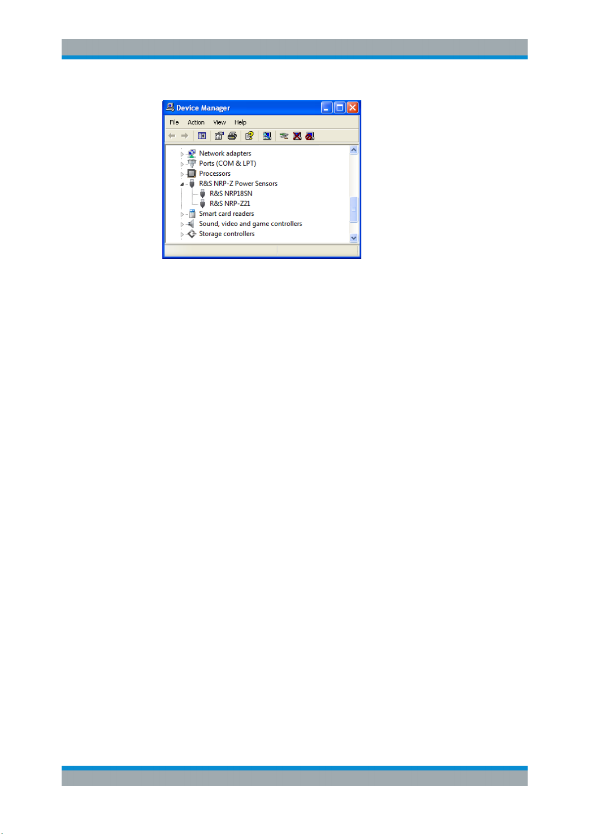
Figure 3-17: Device Manager
If the power sensor and its drivers are installed and working properly, it is listed in
the "R&S NRP-Z Power Sensors" section of the "Device Manager". If an unknown
device is shown instead, check the items listed in the Chapter 3.7.3, "USB Related
Problems", on page 23.
3.7.3 USB Related Problems
Hardware
●
Use only high-speed hubs with own power supply.
●
Disconnect the power supply of the hub when switching off the computer. Connect
the hub's power supply before starting Microsoft®Windows.
●
Do not cascade hubs unnecessarily.
●
Use only connection cables of high speed USB 2.0 hubs.
●
Exchange hub if all points above are not successful.
Software
●
Use one of the supported Microsoft®Windows operating systems:
–
Microsoft®Windows XP with the latest available service pack for Microsoft®Windows XP, i.e. SP2
–
Microsoft®Windows Vista
–
Microsoft®Windows 7
–
Microsoft®Windows 8/8.1
●
Use the latest version of the R&S NRP-Toolkit software (version 4.4.0 or higher,
available at http://www.rohde-schwarz.com/en/software/nrp_s_sn/
under Downloads > Firmware/Software).
23User Manual 1173.0314.02 ─ 07

R&S®NRPV
Quick Start Guide
GUI Overview
4 Quick Start Guide
This section introduces the graphical user interface and contains some basics to power
measurement.
An instruction to perform a standard continuous average power measurement takes
you step-by-step through the information required, to get used to the R&S NRPV basic
modes of operation.
The Quick Start Guide contains:
●
Chapter 4.1, "GUI Overview", on page 24
Describes briefly the main components of the user interface. In general, the
menus, dialogs and functions are largely self-explanatory. Characteristics to specific applications or settings are explicitly stated.
For detailed information on every item of the GUI refer to Chapter 5.1, "Graphical
User Interface (GUI)", on page 47.
●
Chapter 4.2, "Basic Information on Power Measurement", on page 29
Contains some information on power measurement for RF and microwave signals.
●
Chapter 4.3, "Performing a Measurement with R&S NRPV", on page 31
Describes how to get started by selecting the power sensor, the signal channel,
configuring the test signal and results display.
4.1 GUI Overview
Starting the R&S NRPV software the main application window opens. The appearance
is based on the Microsoft®Windows layout. Measurements are displayed in additional
windows. The appearance of those windows varies, depending on the measurement
mode and the required settings.
24User Manual 1173.0314.02 ─ 07
R&S®NRPV
4.1.1 Windows
Quick Start Guide
GUI Overview
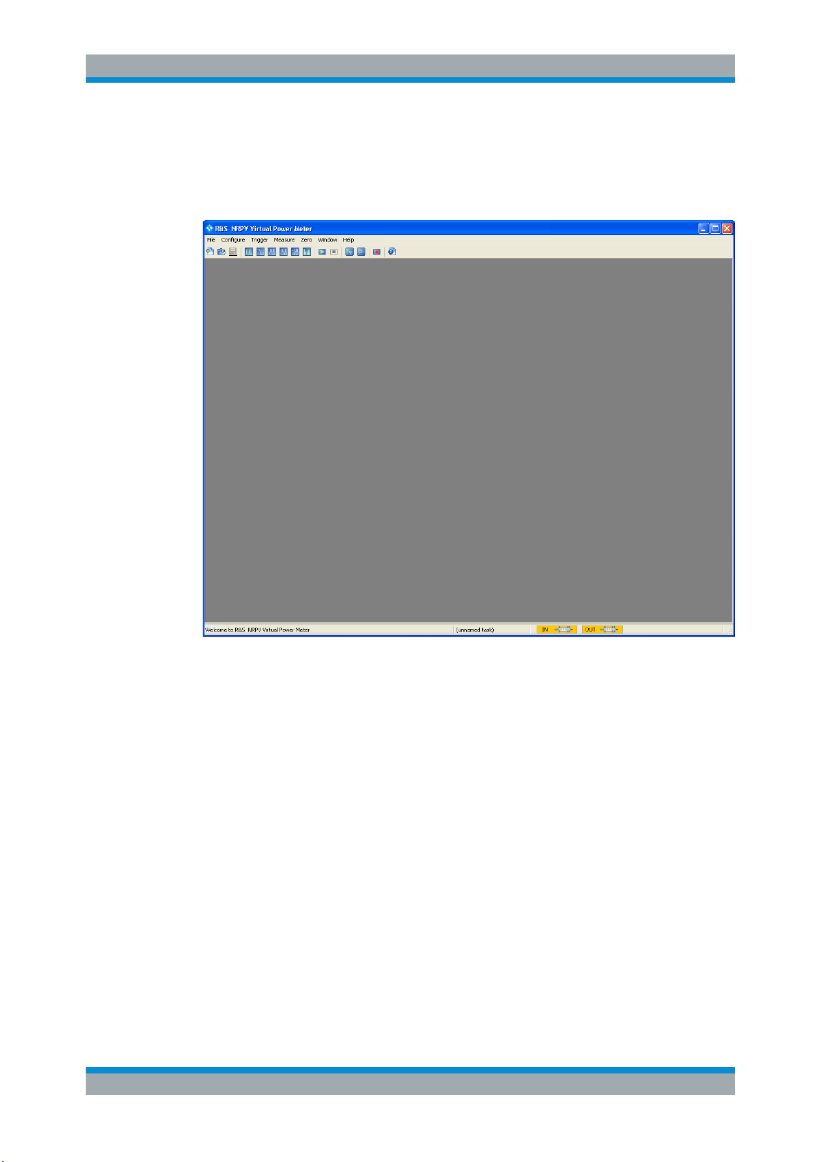
Main Application window
Figure 4-1: Main application window of R&S NRPV
The main window of the application covers a menu bar with several pull-down menus
and a toolbar with icons of the most important functions. Similar to Microsoft®Office
functionality, the icon buttons are the alternative possibility for starting a function. The
status bar informs about the connected power sensors and the currently active tasks.
Measurement windows
Measurement windows look different depending on the measurement mode. It is distinguished between numerical and graphic measurement windows.
25User Manual 1173.0314.02 ─ 07

R&S®NRPV
Quick Start Guide
GUI Overview
Figure 4-2: Numeric measurement window of R&S NRPV
Figure 4-3: Trace window of R&S NRPV
Measurement windows are tiled in several sections.
In the display area, you can graphically display the measurement results. On the right
the control panel provides softkeys for accessing further dialogs and entry fields with
measurement related settings. In the lower area of the window, measurement panels
indicate numerical measurement results.
Additionally, you can open a context-sensitive menu within each results display, also
providing access to further functions.
26User Manual 1173.0314.02 ─ 07
R&S®NRPV
4.1.2 Dialogs
Quick Start Guide
GUI Overview
Configuration dialogs are designed in Microsoft®Windows format, covering the same
main elements, as e.g. tabs, entry fields, check boxes or buttons. Each dialog provides
buttons to apply, confirm or cancel the entered settings
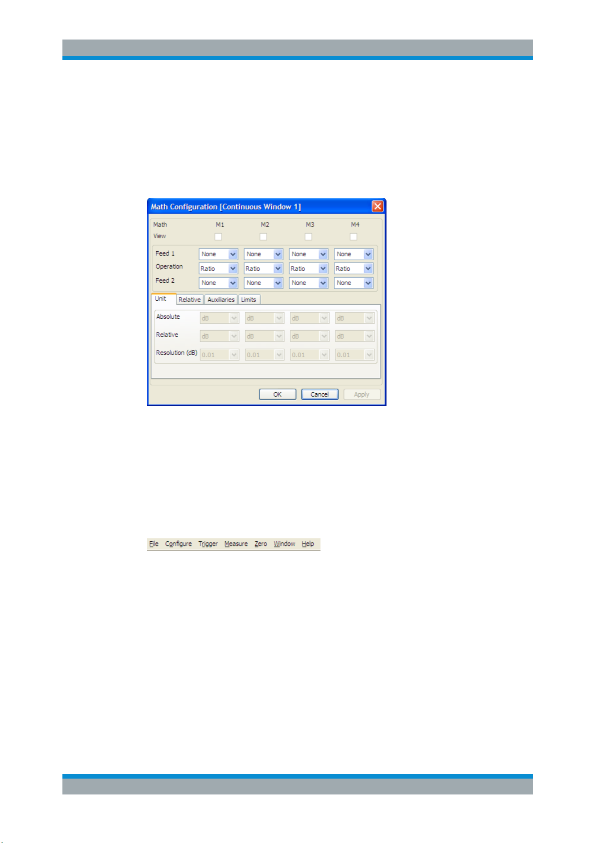
Configuration dialog
Figure 4-4: Configuration dialog
Configuration dialogs cover entry fields for measurement related settings.
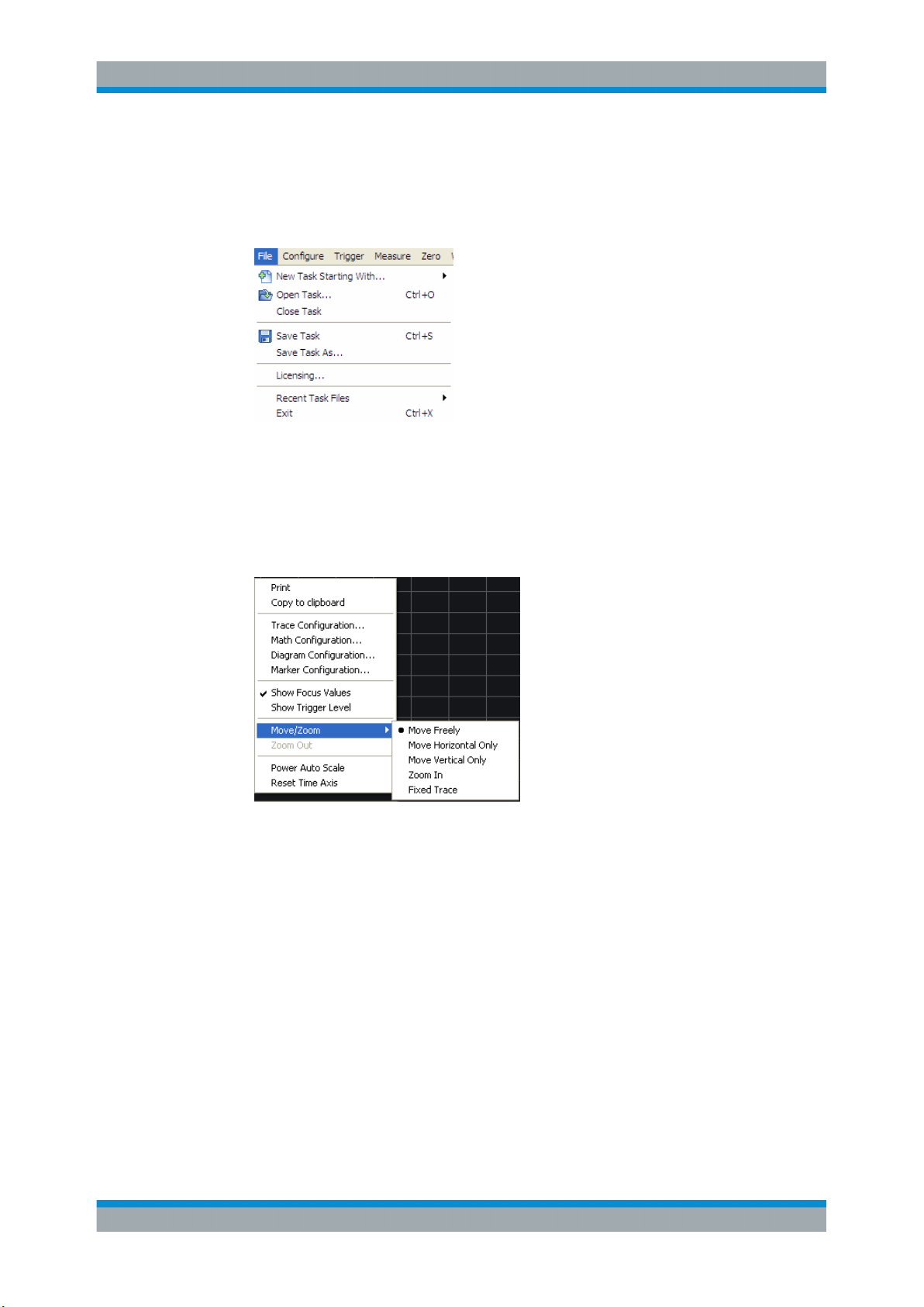
4.1.3 Menus
The menu bar of R&S NRPV contains the main menu items. Some items include submenus with additional functions.
Figure 4-5: Menu bar
The following main menus are available:
●
File: Contains all functions that belong to file management.
●
Configure: Contains basic parameters for configuring a measurement, such as frequency, channel settings or predefined digital communication signals. In addition,
you can determine the colors for displays and curves individually.
●
Trigger: Contains the functions for setting the parameters of externally connected
trigger sources.
●
Measure: Menu for selecting the measurement mode.
●
Zero: Menu for zero error correction.
●
Window: Menu containing the functions for window handling.
27User Manual 1173.0314.02 ─ 07
R&S®NRPV
Quick Start Guide
GUI Overview
●
Help: R&S NRPV Help.
► To access a menu use the mouse or the [ALT+<key>] combination on the key-
board.
Figure 4-6: Standard menu
Within the results display of a measurement window, you can also access the configuration dialogs or additional functions via context-sensitive menus.
► To access a context-sensitive menu, right click in a measurement window.
Figure 4-7: Context-sensitive menu
See
Chapter 5.1.4.2, "Context-sensitive Menus", on page 60 for detailed informa-
tion.
28User Manual 1173.0314.02 ─ 07
R&S®NRPV
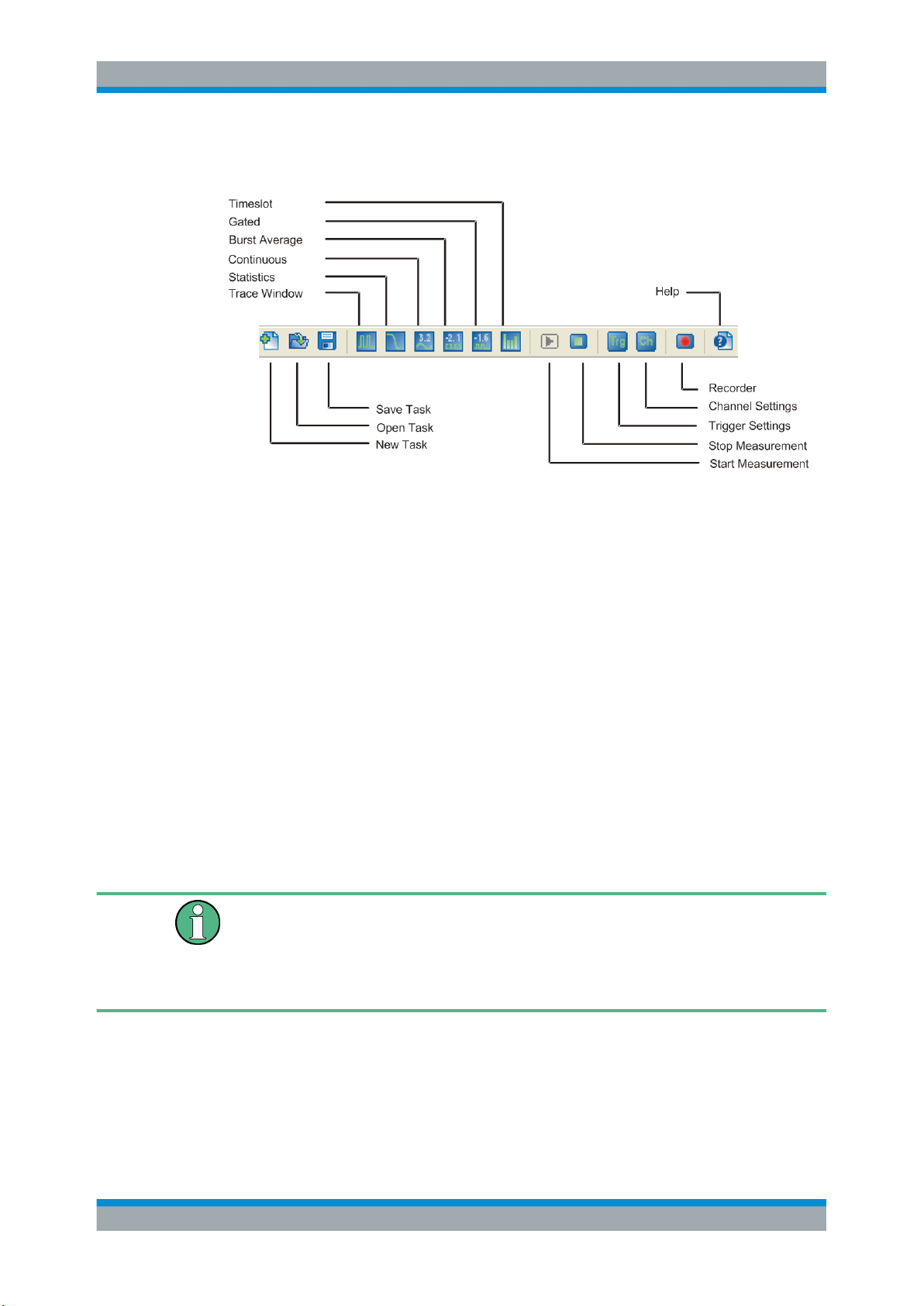
4.1.4 Toolbar
Quick Start Guide
Basic Information on Power Measurement
Figure 4-8: Toolbar
The toolbar of the main application window covers icons of the most important functions.
► To start a function of the R&S NRPV toolbar, perform one of the following:
● In the toolbar, select the corresponding icon.
● On the keyboard, use the associated shortcut.
Each icon features a corresponding item in the menu lists. For detailed assignment on
icons and shortcuts to the corresponding functions see Chapter 5.1.5, "Icons, Toolbar
and Shortcuts", on page 61.
4.2 Basic Information on Power Measurement
The following sections contain some basics to power measurement for RF and microwave signals.
Some contents of the following sections are taken from the R&S brochure 'Voltage and
Power Measurements - Fundamentals, Definitions, and Products'. You can find the
brochure for download on the R&S Website http://www.rohde-schwarz.com/en/product/
nrpz.html
.
4.2.1 Introduction
The intensity of RF and microwave signals is given in terms of power. Therefore, measuring electrical power is significant for RF and microwave applications.
29User Manual 1173.0314.02 ─ 07

R&S®NRPV
Quick Start Guide
Basic Information on Power Measurement
With the development of carrier-based telecommunications also the measurement of
power, voltage and current has improved. Mainly based on converting electrical energy
into heat, direct voltage and current measurement can be made up into the GHz range.
Voltage and current are less appropriate because they depend on the physical characteristics of the transmission medium and field strength. They differ for the same transmitted power. Also, voltage and current can not directly be measured in waveguides
and for standing waves large measurement errors occur.
The rate of energy flow, power, is the absolute measurable value of the wave intensity.
In high frequencies ranges the wavelength of the electromagnetic field affects the wave
properties and characteristics, caused by lines and subassemblies. To be taken into
account for power measurement, wavelength and magnitude of the electromagnetic
field are of the same order as the signal wavelength. Additionally, all components in a
power transmitter or amplifier, e.g. the AC line connector, the cooling system or coaxial
RF output, depend on the magnitude of the RF power.
Besides the effects mentioned above, several critical factors may cause errors in the
measurement of RF power. For instance, the loading effects of measuring equipment
on the DUT, inherent physical factors or unsuitable probes may increase measurement
uncertainty.
To carry out a power measurement correctly, it is essential to assort the most appropriate measurement equipment for the respective application. For a wide variety of tasks
Rohde & Schwarz provides suitable power meters and power sensors.
4.2.2 Definition of Electrical Power
Power is defined as the amount of energy absorbed or transferred in a system per unit
of time. The power transmitted across an interface is then the product of the instantaneous values of current and voltage at that interface.
p
= v
x I
(t)
(t)
(t)
For sinusoidal signals encountered in RF and microwave engineering, the instantaneous power p(t) oscillates about the average power at a frequency that is twice that of
the original waveform. Only the average power can be measured in practice and is
referred to as power P. P is referred to as active power and is related to the RMS voltage V, the RMS current I and the phase φ by the following equation:
P = V x I x cosφ
For modulated sinusoidal signals the average of P over the modulation period is
called the average power P
This power e.g. is indicated by a thermal power meter (sensor).
avg
4.2.3 Units and Power Level
Electrical power is measured in W [Watt]. Because of the large power ranges that have
to be measured, values are usually expressed as the log of a power ratio. A relative
30User Manual 1173.0314.02 ─ 07
 Loading...