

R&S®FSWP
Phase Noise Analyzer
User Manual
(;ÛÆQ2)
1177563302
Version 13

This manual describes the following R&S®FSWP models with firmware version 2.00 or higher:
●
R&S®FSWP8 (1322.8003K08)
●
R&S®FSWP26 (1322.8003K26)
●
R&S®FSWP50 (1322.8003K50)
In addition, the following options are described:
●
R&S FSWP-B21 (1325.3848.02)
●
R&S FSWP-B24 (1325.3725.08)
●
R&S FSWP-B24 (1325.3725.26)
●
R&S FSWP-B24 (1325.3725.50)
●
R&S FSWP-B60 (1322.9800.08)
●
R&S FSWP-B60 (1322.9800.26)
●
R&S FSWP-B60 (1322.9800.50)
●
R&S FSWP-B64 (1322.9900.26)
●
R&S FSWP-B64 (1322.9900.50)
●
R&S FSWP-K4 (1325.5034.02)
●
R&S FSWP-K33 (1325.5040.02)
© 2021 Rohde & Schwarz GmbH & Co. KG
Mühldorfstr. 15, 81671 München, Germany
Phone: +49 89 41 29 - 0
Email: info@rohde-schwarz.com
Internet: www.rohde-schwarz.com
Subject to change – data without tolerance limits is not binding.
R&S® is a registered trademark of Rohde & Schwarz GmbH & Co. KG.
Trade names are trademarks of the owners.
1177.5633.02 | Version 13 | R&S®FSWP
Throughout this manual, products from Rohde & Schwarz are indicated without the ® symbol , e.g. R&S®FSWP is indicated as
R&S FSWP.

R&S®FSWP
Contents
Contents
1 Safety and Regulatory Information.................................................... 15
1.1 Safety Instructions......................................................................................................15
1.2 Warning Messages in the Documentation................................................................17
1.3 Korea Certification Class A........................................................................................18
2 Documentation Overview....................................................................19
2.1 Getting Started Manual...............................................................................................19
2.2 User Manuals and Help...............................................................................................19
2.3 Service Manual............................................................................................................ 19
2.4 Instrument Security Procedures................................................................................20
2.5 Printed Safety Instructions........................................................................................ 20
2.6 Data Sheets and Brochures....................................................................................... 20
2.7 Release Notes and Open Source Acknowledgment (OSA).....................................20
2.8 Application Notes, Application Cards, White Papers, etc.......................................20
3 Preparing for Use.................................................................................21
3.1 Lifting and Carrying.................................................................................................... 21
3.2 Unpacking and Checking........................................................................................... 21
3.3 Choosing the Operating Site......................................................................................21
3.4 Setting Up the R&S FSWP..........................................................................................22
3.4.1 Placing the Product on a Bench Top.............................................................................22
3.4.2 Mounting the R&S FSWP in a Rack..............................................................................23
3.5 Connecting the AC Power.......................................................................................... 23
3.6 Switching the Instrument On and Off........................................................................24
3.7 Connecting to LAN......................................................................................................25
3.8 Connecting a Keyboard..............................................................................................26
3.9 Connecting an External Monitor................................................................................27
3.10 Windows Operating System.......................................................................................28
3.11 Logging On..................................................................................................................30
3.12 Checking the Supplied Options.................................................................................31
3.13 Performing a Self-Alignment......................................................................................32
3.14 Considerations for Test Setup................................................................................... 32
3User Manual 1177.5633.02 ─ 13

R&S®FSWP
4.1.1 Display (Touchscreen)...................................................................................................35
4.1.2 Power Key.....................................................................................................................36
4.1.3 System Control Keys.....................................................................................................36
4.1.4 The Function Keys........................................................................................................ 37
4.1.5 The Keypad...................................................................................................................38
4.1.6 Navigation Control.........................................................................................................39
4.1.7 RF Input (50 Ω)............................................................................................................. 40
4.1.8 Signal Source Output.................................................................................................... 41
4.1.9 USB Ports..................................................................................................................... 41
4.1.10 Power Sensors..............................................................................................................41
4.1.11 Probe Power Connector (3 Pins).................................................................................. 42
Contents
4 Instrument Tour....................................................................................34
4.1 The Front Panel........................................................................................................... 34
4.1.12 Noise Source Control.................................................................................................... 42
4.1.13 Trigger Input and Output............................................................................................... 42
4.1.14 Baseband Input............................................................................................................. 42
4.1.15 External Mixer (Optional).............................................................................................. 43
4.1.16 DC Power Supply..........................................................................................................43
4.1.17 LO AUX Input (Optional)............................................................................................... 43
4.2 The Rear Panel............................................................................................................ 44
4.2.1 Removable Hard Disk................................................................................................... 45
4.2.2 AC Power Supply Connection and Main Power Switch................................................ 45
4.2.3 Display Port and DVI.....................................................................................................45
4.2.4 LAN............................................................................................................................... 46
4.2.5 USB Ports..................................................................................................................... 46
4.2.6 IF / Video / Demod Output.............................................................................................46
4.2.7 IF Wide Out................................................................................................................... 46
4.2.8 Sync Trigger Input and Output...................................................................................... 47
4.2.9 AUX Port....................................................................................................................... 47
4.2.10 GPIB Interface...............................................................................................................47
4.2.11 External Generator Control (Optional).......................................................................... 47
4.2.12 OCXO (Optional)...........................................................................................................48
4.2.13 REF INPUT / REF OUTPUT......................................................................................... 48
4User Manual 1177.5633.02 ─ 13

R&S®FSWP
4.2.14 Labels on R&S FSWP...................................................................................................49
4.2.15 Device ID.......................................................................................................................49
5.2.1 Measurement Selection................................................................................................ 53
5.2.2 The Phase Noise Measurement....................................................................................53
5.2.3 The Additive Noise Measurement................................................................................. 56
5.2.4 The Baseband Noise Measurement..............................................................................58
5.2.5 The Pulsed Phase Noise Measurement........................................................................60
5.2.6 The Pulsed Additive Noise Measurement..................................................................... 60
5.2.7 Adding Another Measurement Channel........................................................................ 62
Contents
5 Trying Out the Instrument................................................................... 50
5.1 Initial Setup..................................................................................................................51
5.2 Measurements............................................................................................................. 52
5.3 Result Evaluation........................................................................................................ 62
5.3.1 Trace Smoothing...........................................................................................................63
5.3.2 Integration Ranges........................................................................................................65
5.3.3 The Cross-Correlation Gain Indicator........................................................................... 66
5.3.4 Miscellaneous Evaluation Tools.................................................................................... 67
5.4 Measurement Configuration...................................................................................... 68
5.4.1 Frequency Configuration...............................................................................................68
5.4.2 The Half Decade Configuration Table........................................................................... 70
5.4.3 Pulsed Measurement Configuration..............................................................................70
5.4.4 Signal Generation......................................................................................................... 71
5.4.5 DUT Power Supply........................................................................................................73
6 Operating the Instrument.................................................................... 74
6.1 Understanding the Display Information....................................................................74
6.1.1 Channel Bar.................................................................................................................. 75
6.1.2 Window Title Bar........................................................................................................... 77
6.1.3 Marker Information........................................................................................................ 78
6.1.4 Spot Noise Information..................................................................................................78
6.1.5 Measurement Progress Information..............................................................................79
6.1.6 Frequency Information in Diagram Footer.................................................................... 80
6.1.7 Instrument and Status Information................................................................................ 80
6.1.8 Error Information........................................................................................................... 81
5User Manual 1177.5633.02 ─ 13

R&S®FSWP
6.2.1 Toolbar.......................................................................................................................... 83
6.2.2 Softkeys........................................................................................................................ 84
6.2.3 Context Menus.............................................................................................................. 85
6.2.4 On-screen Keyboard..................................................................................................... 85
6.4.1 Entering Numeric Parameters.......................................................................................86
6.4.2 Entering Alphanumeric Parameters.............................................................................. 87
6.5.1 Activating and Deactivating Channels...........................................................................89
6.5.2 Laying out the Result Display with the SmartGrid.........................................................90
6.5.3 Changing the Size of Windows..................................................................................... 94
Contents
6.2 Accessing Functions.................................................................................................. 82
6.3 Changing the Focus....................................................................................................86
6.4 Entering Data...............................................................................................................86
6.5 Displaying Results...................................................................................................... 88
6.5.4 Switching Between a Split and Maximized Window Display......................................... 95
6.5.5 Changing the Display.................................................................................................... 95
6.6 Remote Control........................................................................................................... 96
6.6.1 Remote Desktop Connection........................................................................................ 96
6.6.2 Connecting a PC via the GPIB Interface.......................................................................96
7 Applications..........................................................................................98
7.1 R&S MultiView............................................................................................................. 98
7.2 Available Applications................................................................................................99
7.3 Starting an Application.............................................................................................101
7.4 Running a Sequence of Measurements.................................................................. 103
7.4.1 The Sequencer Concept............................................................................................. 103
7.4.2 Sequencer Settings.....................................................................................................105
7.4.3 How to Set Up the Sequencer.....................................................................................105
8 Measurements and Result Displays.................................................107
8.1 Basics on Phase Noise Measurements...................................................................107
8.1.1 Residual Effects.......................................................................................................... 107
8.2 Performing Measurements.......................................................................................108
8.3 Selecting Measurements.......................................................................................... 110
8.4 Result Displays..........................................................................................................112
6User Manual 1177.5633.02 ─ 13

R&S®FSWP
9.2.1 RF Input...................................................................................................................... 125
9.2.2 Baseband Input........................................................................................................... 127
9.2.3 External Mixers........................................................................................................... 128
9.3.1 Signal Attenuation....................................................................................................... 142
9.3.2 Amplitude Characteristics........................................................................................... 143
9.3.3 Diagram Scale.............................................................................................................145
9.5.1 Triggered Measurements (Phase Noise CW)............................................................. 151
Contents
9 Common Measurement Settings...................................................... 123
9.1 Configuration Overview............................................................................................123
9.2 Input Source.............................................................................................................. 125
9.3 Level Characteristics................................................................................................ 142
9.4 Frequency.................................................................................................................. 146
9.5 Noise Measurement Configuration..........................................................................151
9.5.2 Measurement Range...................................................................................................151
9.5.3 Noise Configuration.....................................................................................................152
9.5.4 Integrated Measurement Configuration.......................................................................158
9.5.5 Spot Noise Information................................................................................................161
9.5.6 Spur Display................................................................................................................162
9.5.7 Frequency Stability Configuration............................................................................... 164
9.6 Output........................................................................................................................ 165
9.6.1 DC Source Configuration............................................................................................ 165
9.6.2 Signal Source Configuration....................................................................................... 168
9.6.3 Miscellaneous Output..................................................................................................172
9.7 Pulsed Phase Noise and Pulsed Additive Noise Configuration........................... 173
9.8 VCO Characterization Configuration.......................................................................177
9.8.1 Sweep Configuration...................................................................................................177
9.8.2 Trace Configuration.....................................................................................................180
9.9 Spot Noise vs Tune Configuration...........................................................................180
9.9.1 Trace Configuration.....................................................................................................181
9.10 PN Transient Analysis Configuration......................................................................181
9.10.1 Frequency Configuration.............................................................................................182
9.10.2 Trigger Configuration...................................................................................................184
9.10.3 Data Acquisition.......................................................................................................... 186
7User Manual 1177.5633.02 ─ 13

R&S®FSWP
9.10.4 Amplitude Configuration..............................................................................................187
9.10.5 Diagram Scale.............................................................................................................188
9.10.6 Settling Time............................................................................................................... 190
9.10.7 Frequency Deviation................................................................................................... 191
9.10.8 Trace Configuration.....................................................................................................191
9.10.9 Marker Configuration...................................................................................................192
9.10.10 Limit Lines................................................................................................................... 192
10.1.1 Basic Result Displays..................................................................................................193
10.1.2 Laying out the Result Display with the SmartGrid.......................................................193
Contents
10 Common Analysis and Display Functions...................................... 193
10.1 Result Display Configuration...................................................................................193
10.2 Zoomed Displays...................................................................................................... 198
10.2.1 Single Zoom Versus Multiple Zoom............................................................................ 198
10.2.2 Zoom Functions.......................................................................................................... 199
10.2.3 How to Zoom Into a Diagram...................................................................................... 200
10.3 Trace Configuration.................................................................................................. 202
10.3.1 Basics on Traces.........................................................................................................202
10.3.2 Trace Configuration.....................................................................................................206
10.3.3 Trace Export and Import..............................................................................................209
10.3.4 Copying Traces........................................................................................................... 214
10.3.5 Trace Math.................................................................................................................. 214
10.3.6 Trace Labels................................................................................................................215
10.3.7 How to Configure Traces.............................................................................................215
10.3.8 References..................................................................................................................216
10.4 Markers...................................................................................................................... 223
10.4.1 Basics on Markers and Marker Functions...................................................................223
10.4.2 Marker Settings........................................................................................................... 225
10.4.3 Marker Search Settings and Positioning Functions.................................................... 229
10.5 Limit Lines................................................................................................................. 232
10.5.1 Basics on Limit Lines.................................................................................................. 232
10.5.2 Limit Line Settings and Functions............................................................................... 236
10.5.3 How to Define Limit Lines........................................................................................... 240
11 Data Management.............................................................................. 244
8User Manual 1177.5633.02 ─ 13

R&S®FSWP
11.3.1 Quick Save/Quick Recall.............................................................................................248
11.3.2 Configurable Storage and Recall................................................................................ 251
11.3.3 How to Save and Load Instrument Settings................................................................256
11.5.1 Print and Screenshot Settings.....................................................................................260
11.5.2 How to Store or Print Screenshots of the Display....................................................... 269
11.5.3 Example for Storing Multiple Measurement Results to a PDF File............................. 272
Contents
11.1 Restoring the Default Instrument Configuration (Preset)..................................... 244
11.2 Protecting Data Using the Secure User Mode........................................................245
11.3 Storing and Recalling Instrument Settings and Measurement Data....................247
11.4 Import/Export Functions.......................................................................................... 258
11.5 Creating Screenshots of Current Measurement Results and Settings................260
12 General Instrument Setup................................................................. 275
12.1 Alignment...................................................................................................................275
12.1.1 Basics on Alignment....................................................................................................275
12.1.2 Alignment Settings...................................................................................................... 277
12.1.3 How to Perform a Self-Test......................................................................................... 280
12.1.4 How to Align the Instrument........................................................................................ 280
12.1.5 How to Align the Touchscreen.....................................................................................281
12.2 Display Settings........................................................................................................ 281
12.2.1 Display Settings.......................................................................................................... 281
12.2.2 How to Configure the Colors for Display and Printing.................................................290
12.2.3 How to Work with the Soft Front Panels......................................................................291
12.3 Reference Frequency Settings................................................................................ 292
12.4 System Configuration Settings................................................................................296
12.4.1 Hardware Information..................................................................................................296
12.4.2 Information on Versions and Options..........................................................................297
12.4.3 System Messages.......................................................................................................298
12.4.4 Firmware Updates.......................................................................................................299
12.4.5 General Configuration Settings................................................................................... 301
12.5 Service Functions..................................................................................................... 303
12.5.1 R&S Support Information............................................................................................ 304
12.5.2 Self-test Settings and Results..................................................................................... 305
12.5.3 Calibration Signal Display........................................................................................... 306
9User Manual 1177.5633.02 ─ 13

R&S®FSWP
12.5.4 Service Functions........................................................................................................308
12.5.5 Hardware Diagnostics................................................................................................. 309
13.1.1 Remote Control Interfaces and Protocols....................................................................311
13.1.2 SCPI (Standard Commands for Programmable Instruments).....................................320
13.1.3 VISA Libraries............................................................................................................. 320
13.1.4 Messages....................................................................................................................321
13.1.5 SCPI Command Structure...........................................................................................322
13.1.6 Command Sequence and Synchronization.................................................................330
13.1.7 Status Reporting System............................................................................................ 332
13.1.8 General Programming Recommendations..................................................................349
Contents
13 Network and Remote Operation........................................................311
13.1 Remote Control Basics.............................................................................................311
13.2 The IECWIN Tool........................................................................................................350
13.3 Network and Remote Control Settings................................................................... 351
13.3.1 General Network Settings........................................................................................... 352
13.3.2 GPIB Settings..............................................................................................................354
13.3.3 Compatibility Settings..................................................................................................357
13.3.4 LAN Settings............................................................................................................... 358
13.3.5 HUMS Settings............................................................................................................360
13.3.6 Remote Errors.............................................................................................................366
13.3.7 Returning to Manual Mode ("Local")........................................................................... 367
13.4 How to Set Up a Network and Remote Control...................................................... 368
13.4.1 How to Configure a Network....................................................................................... 369
13.4.2 How to Operate the Instrument Without a Network.....................................................375
13.4.3 How to Log on to the Network.....................................................................................375
13.4.4 How to Share Directories (only with Microsoft Networks)........................................... 378
13.4.5 How to Control the R&S FSWP via the Web Browser Interface..................................378
13.4.6 How to Deactivate the Web Browser Interface............................................................379
13.4.7 How to Set Up Remote Desktop................................................................................. 380
13.4.8 How to Start a Remote Control Session from a PC.................................................... 386
13.4.9 How to Return to Manual Operation............................................................................387
14 Remote Control.................................................................................. 388
14.1 Conventions Used in SCPI Command Descriptions..............................................388
10User Manual 1177.5633.02 ─ 13

R&S®FSWP
14.4.1 Selecting Mode and Applications................................................................................ 394
14.4.2 Performing a Sequence of Measurements..................................................................398
14.4.3 Programming Example: Performing a Sequence of Measurements........................... 400
14.5.1 Measurement Selection.............................................................................................. 402
14.5.2 Performing Measurements..........................................................................................404
14.5.3 Querying Results.........................................................................................................407
14.5.4 Programming Examples..............................................................................................417
14.6.1 Remote Commands to Configure the Input Source.................................................... 418
Contents
14.2 Common Suffixes......................................................................................................389
14.3 Common Commands................................................................................................ 389
14.4 Selecting the Operating Mode and Application..................................................... 394
14.5 Measurements and Result Displays........................................................................402
14.6 Common Measurement Settings............................................................................. 418
14.6.2 Output......................................................................................................................... 433
14.6.3 Remote Commands to Configure User Ports..............................................................446
14.6.4 Remote Commands to Configure Level Characteristics............................................. 448
14.6.5 Remote Commands to Configure the Frequency........................................................454
14.6.6 Phase Noise Measurement Configuration.................................................................. 459
14.6.7 Pulsed Phase Noise Configuration............................................................................. 479
14.6.8 VCO Characterization Configuration...........................................................................482
14.6.9 Spot Noise vs Tune Configuration...............................................................................485
14.6.10 Transient Analysis.......................................................................................................489
14.7 Common Analysis and Display Functions............................................................. 505
14.7.1 Display Configuration.................................................................................................. 505
14.7.2 Zoom........................................................................................................................... 514
14.7.3 Trace Configuration.....................................................................................................517
14.7.4 Marker......................................................................................................................... 529
14.7.5 Limit Lines................................................................................................................... 542
14.7.6 Examples: Configuring the Result Display.................................................................. 554
14.8 Managing Settings and Results...............................................................................557
14.8.1 Managing Files............................................................................................................558
14.8.2 Selecting Items to Store.............................................................................................. 563
14.8.3 Saving and Loading Instrument Settings.................................................................... 566
11User Manual 1177.5633.02 ─ 13

R&S®FSWP
14.8.4 Storing and Printing Screenshots................................................................................570
14.8.5 Saving Measurement Results..................................................................................... 581
14.8.6 Examples: Managing Data.......................................................................................... 582
14.9.1 Basic Instrument Setup............................................................................................... 585
14.9.2 Configuring the Reference Frequency........................................................................ 586
14.9.3 Calibrating the R&S FSWP and Checking Temperature............................................. 591
14.9.4 Customizing the Screen Layout.................................................................................. 595
14.9.5 Configuring Network and Remote Control.................................................................. 601
14.9.6 Configuring HUMS...................................................................................................... 606
14.9.7 Checking the System Configuration............................................................................612
14.9.8 Using Service Functions............................................................................................. 618
14.9.9 Reference: Command Set of 5052 Emulation.............................................................622
Contents
14.9 Configuring the R&S FSWP......................................................................................585
14.9.10 Reference: Command Set of Emulated PSA Models..................................................623
14.10 Using the Status Register........................................................................................ 627
14.10.1 General Status Register Commands.......................................................................... 628
14.10.2 Reading Out the CONDition Part................................................................................ 628
14.10.3 Reading Out the EVENt Part.......................................................................................629
14.10.4 Controlling the ENABle Part........................................................................................629
14.10.5 Controlling the Negative Transition Part......................................................................630
14.10.6 Controlling the Positive Transition Part....................................................................... 631
14.11 Programming Examples...........................................................................................631
14.11.1 Service Request..........................................................................................................632
15 Troubleshooting................................................................................. 641
15.1 Collecting Information for Support..........................................................................641
15.2 Contacting Customer Support.................................................................................643
16 Transporting.......................................................................................644
17 Maintenance, Storage, Transport and Disposal.............................. 645
17.1 Cleaning..................................................................................................................... 645
17.2 Storage.......................................................................................................................645
17.3 Transporting.............................................................................................................. 645
12User Manual 1177.5633.02 ─ 13

R&S®FSWP
Contents
17.4 Disposal..................................................................................................................... 646
List of commands.............................................................................. 647
Index....................................................................................................660
13User Manual 1177.5633.02 ─ 13

R&S®FSWP
Contents
14User Manual 1177.5633.02 ─ 13

R&S®FSWP
Safety and Regulatory Information
Safety Instructions
1 Safety and Regulatory Information
The product documentation helps you use the product safely and efficiently. Follow the
instructions provided here and in the Chapter 1.1, "Safety Instructions", on page 15.
Intended use
The product is intended for the development, production and verification of electronic
components and devices in industrial, administrative, and laboratory environments.
Use the product only for its designated purpose. Observe the operating conditions and
performance limits stated in the data sheet.
Target audience
Where do I find safety information?
Safety information is part of the product documentation. It warns you of potential dangers and gives instructions on how to prevent personal injury or damage caused by
dangerous situations. Safety information is provided as follows:
●
In Chapter 1.1, "Safety Instructions", on page 15. The same information is provided in many languages as printed "Safety Instructions". The printed "Safety
Instructions" are delivered with the product.
●
Throughout the documentation, safety instructions are provided when you need to
take care during setup or operation.
1.1 Safety Instructions
Products from the Rohde & Schwarz group of companies are manufactured according
to the highest technical standards. To use the products safely, follow the instructions
provided here and in the product documentation. Keep the product documentation
nearby and offer it to other users.
Use the product only for its intended use and within its performance limits. Intended
use and limits are described in the product documentation such as the data sheet,
manuals and the printed "Safety Instructions". If you are unsure about the appropriate
use, contact Rohde & Schwarz customer service.
Using the product requires specialists or specially trained personnel. These users also
need sound knowledge of at least one of the languages in which the user interfaces
and the product documentation are available.
Never open the casing of the product. Only service personnel authorized by
Rohde & Schwarz are allowed to repair the product. If any part of the product is damaged or broken, stop using the product. Contact Rohde & Schwarz customer service at
http://www.customersupport.rohde-schwarz.com.
15User Manual 1177.5633.02 ─ 13

R&S®FSWP
Safety and Regulatory Information
Safety Instructions
Lifting and carrying the product
The product is heavy. Do not move or carry the product by yourself. A single person
can only carry a maximum of 18 kg safely depending on age, gender and physical condition. Look up the maximum weight in the data sheet. Use the product handles to
move or carry the product. Do not lift by the accessories mounted on the product.
Accessories are not designed to carry the weight of the product.
To move the product safely, you can use lifting or transporting equipment such as lift
trucks and forklifts. Follow the instructions provided by the equipment manufacturer.
Choosing the operating site
Only use the product indoors. The product casing is not waterproof. Water that enters
can electrically connect the casing with live parts, which can lead to electric shock,
serious personal injury or death if you touch the casing. If Rohde & Schwarz provides
accessories designed for your product, e.g. a carrying bag, you can use the product
outdoors.
Unless otherwise specified, you can operate the product up to an altitude of 2000 m
above sea level. The product is suitable for pollution degree 2 environments where
nonconductive contamination can occur. For more information on environmental conditions such as ambient temperature and humidity, see the data sheet.
Setting up the product
Always place the product on a stable, flat and level surface with the bottom of the product facing down. If the product is designed for different positions, secure the product so
that it cannot fall over.
If the product has foldable feet, always fold the feet completely in or out to ensure stability. The feet can collapse if they are not folded out completely or if the product is
moved without lifting it. The foldable feet are designed to carry the weight of the product, but not an extra load.
If stacking is possible, keep in mind that a stack of products can fall over and cause
injury.
If you mount products in a rack, ensure that the rack has sufficient load capacity and
stability. Observe the specifications of the rack manufacturer. Always install the products from the bottom shelf to the top shelf so that the rack stands securely. Secure the
product so that it cannot fall off the rack.
Connecting to power
The product is an overvoltage category II product. Connect the product to a fixed
installation used to supply energy-consuming equipment such as household appliances and similar loads. Keep in mind that electrically powered products have risks, such
as electric shock, fire, personal injury or even death.
Take the following measures for your safety:
●
Before switching on the product, ensure that the voltage and frequency indicated
on the product match the available power source. If the power adapter does not
adjust automatically, set the correct value and check the rating of the fuse.
16User Manual 1177.5633.02 ─ 13
R&S®FSWP
Safety and Regulatory Information
Warning Messages in the Documentation
●
Only use the power cable delivered with the product. It complies with country-specific safety requirements. Only insert the plug into an outlet with protective conductor terminal.
●
Only use intact cables and route them carefully so that they cannot be damaged.
Check the power cables regularly to ensure that they are undamaged. Also ensure
that nobody can trip over loose cables.
●
If the product needs an external power supply, use the power supply that is delivered with the product or that is recommended in the product documentation or a
power supply that conforms to the country-specific regulations.
●
Only connect the product to a power source with a fuse protection of maximum
20 A.
●
Ensure that you can disconnect the product from the power source at any time.
Pull the power plug to disconnect the product. The power plug must be easily
accessible. If the product is integrated into a system that does not meet these
requirements, provide an easily accessible circuit breaker at the system level.
Cleaning the product
Use a dry, lint-free cloth to clean the product. When cleaning, keep in mind that the
casing is not waterproof. Do not use liquid cleaning agents.
Meaning of safety labels
Safety labels on the product warn against potential hazards.
Potential hazard
Read the product documentation to avoid personal injury or product damage.
Heavy product
Be careful when lifting, moving or carrying the product. Carrying the product requires a suffi-
cient number of persons or transport equipment.
Electrical hazard
Indicates live parts. Risk of electric shock, fire, personal injury or even death.
Hot surface
Do not touch. Risk of skin burns. Risk of fire.
Protective conductor terminal
Connect this terminal to a grounded external conductor or to protective ground. This connec-
tion protects you against electric shock if an electric problem occurs.
1.2 Warning Messages in the Documentation
A warning message points out a risk or danger that you need to be aware of. The signal word indicates the severity of the safety hazard and how likely it will occur if you do
not follow the safety precautions.
17User Manual 1177.5633.02 ─ 13

R&S®FSWP
1.3 Korea Certification Class A
Safety and Regulatory Information
Korea Certification Class A
WARNING
Potentially hazardous situation. Could result in death or serious injury if not avoided.
CAUTION
Potentially hazardous situation. Could result in minor or moderate injury if not avoided.
NOTICE
Potential risks of damage. Could result in damage to the supported product or to other
property.
이 기기는 업무용(A급) 전자파 적합기기로서 판매자 또는 사용자는 이 점을 주의하시기
바라며, 가정외의 지역에서 사용하는 것을 목적으로 합니다.
18User Manual 1177.5633.02 ─ 13

R&S®FSWP
2.1 Getting Started Manual
Documentation Overview
Service Manual
2 Documentation Overview
This section provides an overview of the R&S FSWP user documentation. Unless
specified otherwise, you find the documents on the R&S FSWP product page at:
www.rohde-schwarz.com/manual/FSWP
Introduces the R&S FSWP and describes how to set up and start working with the
product. Includes basic operations, typical measurement examples, and general information, e.g. safety instructions, etc.
A printed version is delivered with the instrument. A PDF version is available for download on the Internet.
2.2 User Manuals and Help
The user manual contains the description of all instrument modes and functions. It also
provides an introduction to remote control, a complete description of the remote control
commands with programming examples, and information on maintenance, instrument
interfaces and error messages. Includes the contents of the getting started manual.
The contents of the user manual are available as help in the R&S FSWP. The help
offers quick, context-sensitive access to the complete information for the instrument
and its firmware.
The user manual is also available for download or for immediate display on the Internet.
2.3 Service Manual
Describes the performance test for checking the rated specifications, module replacement and repair, firmware update, troubleshooting and fault elimination, and contains
mechanical drawings and spare part lists.
The service manual is available for registered users on the global Rohde & Schwarz
information system (GLORIS):
https://gloris.rohde-schwarz.com
19User Manual 1177.5633.02 ─ 13

R&S®FSWP
2.4 Instrument Security Procedures
2.5 Printed Safety Instructions
2.6 Data Sheets and Brochures
Documentation Overview
Application Notes, Application Cards, White Papers, etc.
Deals with security issues when working with the R&S FSWP in secure areas. It is
available for download on the Internet.
Provides safety information in many languages. The printed document is delivered with
the product.
The data sheet contains the technical specifications of the R&S FSWP. It also lists the
firmware applications and their order numbers, and optional accessories.
The brochure provides an overview of the instrument and deals with the specific characteristics.
See www.rohde-schwarz.com/brochure-datasheet/FSWP
2.7 Release Notes and Open Source Acknowledgment (OSA)
The release notes list new features, improvements and known issues of the current
firmware version, and describe the firmware installation.
The open-source acknowledgment document provides verbatim license texts of the
used open source software.
See www.rohde-schwarz.com/firmware/FSWP
2.8 Application Notes, Application Cards, White Papers, etc.
These documents deal with special applications or background information on particular topics.
See www.rohde-schwarz.com/application/FSWP
20User Manual 1177.5633.02 ─ 13

R&S®FSWP
3.1 Lifting and Carrying
3.2 Unpacking and Checking
Preparing for Use
Choosing the Operating Site
3 Preparing for Use
Here, you can find basic information about setting up the instrument for the first time.
The carrying handles are designed to lift or carry the instrument. Do not apply excessive external force to the handles.
See "Lifting and carrying the product" on page 16.
1. Unpack the R&S FSWP carefully.
2. Retain the original packing material. Use it when transporting or shipping the
R&S FSWP later.
3. Using the delivery notes, check the equipment for completeness.
4. Check the equipment for damage.
If the delivery is incomplete or equipment is damaged, contact Rohde & Schwarz.
3.3 Choosing the Operating Site
Specific operating conditions ensure proper operation and avoid damage to the product and connected devices. For information on environmental conditions such as ambient temperature and humidity, see the data sheet.
See also "Choosing the operating site" on page 16.
Electromagnetic compatibility classes
The electromagnetic compatibility (EMC) class indicates where you can operate the
product. The EMC class of the product is given in the data sheet under "General data".
●
Class B equipment is suitable for use in:
– Residential environments
– Environments that are directly connected to a low-voltage supply network that
supplies residential buildings
●
Class A equipment is intended for use in industrial environments. It can cause
radio disturbances in residential environments due to possible conducted and radiated disturbances. It is therefore not suitable for class B environments.
21User Manual 1177.5633.02 ─ 13
R&S®FSWP
Preparing for Use
If class A equipment causes radio disturbances, take appropriate measures to
eliminate them.
3.4 Setting Up the R&S FSWP
The R&S FSWP is designed for use on a bench top or in a rack.
See also:
●
"Setting up the product" on page 16
●
"Intended use" on page 15
3.4.1 Placing the Product on a Bench Top
To place the product on a bench top
1. Place the product on a stable, flat and level surface. Ensure that the surface can
support the weight of the product. For information on the weight, see the data
sheet.
Setting Up the R&S
FSWP
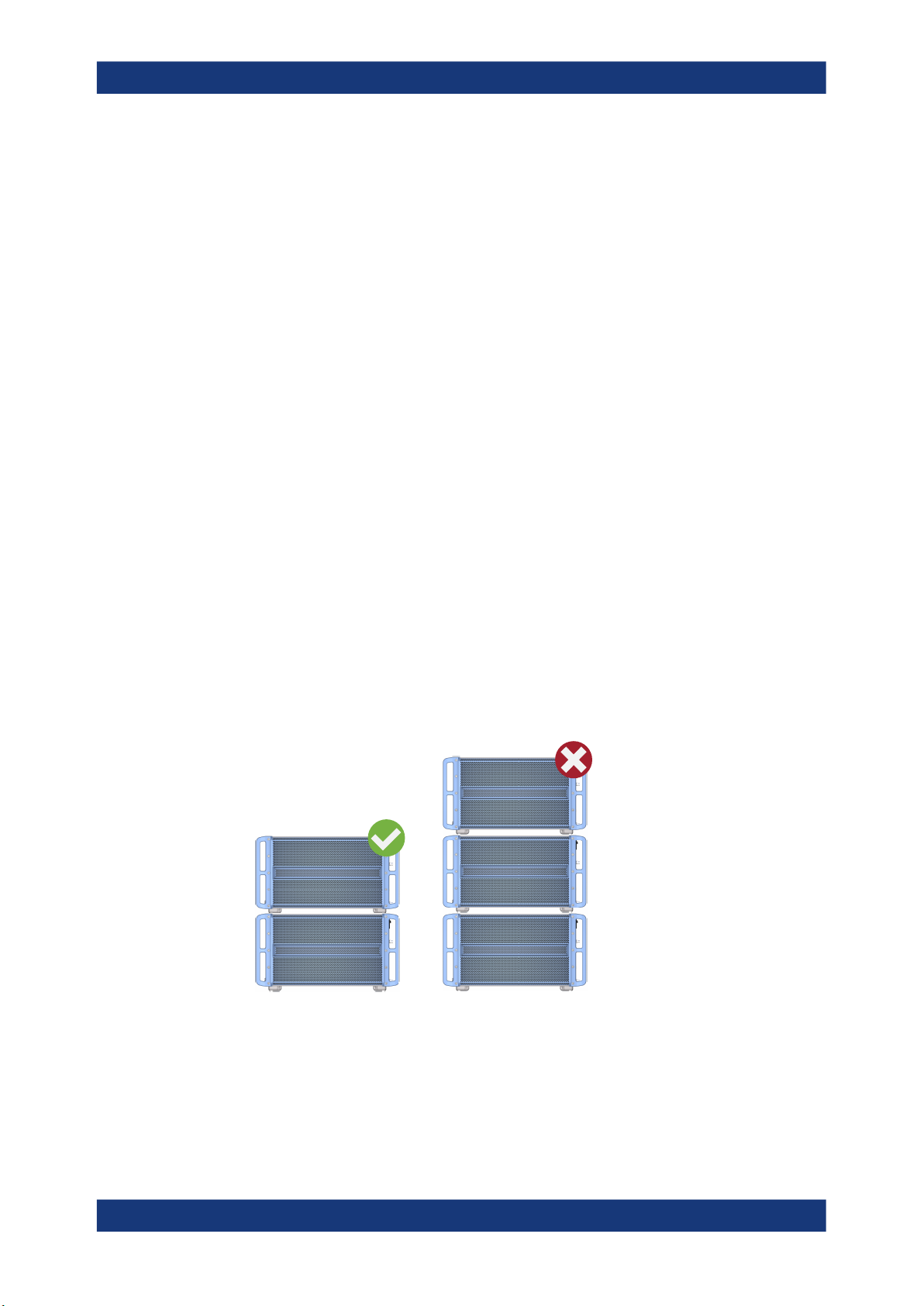
WARNING! A stack of products can fall over and cause injury. Never stack more
2.
than two products. Otherwise, mount them in a rack.
Stack as follows:
● All products must have the same dimensions (width and length).
● Do not exceed a total load of 50 kg placed on the product at the bottom of the
stack.
= Stacked correctly
Left
Right = Stacked incorrectly, too many products
NOTICE! Overheating can damage the product.
3.
Prevent overheating as follows:
22User Manual 1177.5633.02 ─ 13

R&S®FSWP
3.4.2 Mounting the R&S FSWP in a Rack
Preparing for Use
Connecting the AC Power
● Keep a minimum distance of 10 cm between the fan openings of the product
and any object in the vicinity.
● Do not place the product next to heat-generating equipment such as radiators
or other products.
To prepare the rack
1. Observe the requirements and instructions in "Setting up the product" on page 16.
NOTICE! Insufficient airflow can cause overheating and damage the product.
2.
Design and implement an efficient ventilation concept for the rack.
To mount the R&S FSWP in a rack
1. Use an adapter kit to prepare the R&S FSWP for rack mounting.
a) Order the rack adapter kit designed for the R&S FSWP. For the order number,
see the data sheet.
b) Mount the adapter kit. Follow the assembly instructions provided with the
adapter kit.
2. Lift the R&S FSWP to shelf height.
3. Grab the handles and push the R&S FSWP onto the shelf until the rack brackets fit
closely to the rack.
4. Tighten all screws in the rack brackets with a tightening torque of 1.2 Nm to secure
the R&S FSWP in the rack.
To unmount the R&S FSWP from a rack
1. Loosen the screws at the rack brackets.
2. Remove the R&S FSWP from the rack.
3. If placing the R&S FSWP on a bench top again, unmount the adapter kit from the
R&S FSWP. Follow the instructions provided with the adapter kit.
3.5 Connecting the AC Power
In the standard version, the R&S FSWP is equipped with an AC power supply connector.
The R&S FSWP can be used with different AC power voltages and adapts itself automatically to it. Refer to the datasheet for the requirements of voltage and frequency.
For safety information, see "Connecting to power" on page 16.
23User Manual 1177.5633.02 ─ 13
R&S®FSWP
3.6 Switching the Instrument On and Off
Preparing for Use
Switching the Instrument On and Off
To connect the AC power
1. Plug the AC power cable into the AC power connector on the rear panel of the
instrument. Only use the AC power cable delivered with the R&S FSWP.
2. Plug the AC power cable into a power outlet with ground contact.
The required ratings are listed next to the AC power connector and in the data
sheet.
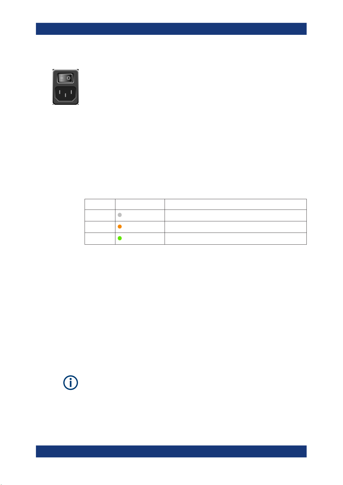
For details on the connector, refer to Chapter 4.2.2, "AC Power Supply Connection and
Main Power Switch", on page 45.
Table 3-1: Overview of power states
Status LED on Power key Position of main power switch
Off
Standby
Ready
gray
orange
green
[0]
[I]
[I]
To switch on the R&S FSWP
The R&S FSWP is off but connected to power.
1. Set the switch on the power supply to position [I].
See Chapter 4.2.2, "AC Power Supply Connection and Main Power Switch",
on page 45.
The LED of the Power key is orange.
See Chapter 4.1.2, "Power Key", on page 36.
2. Press the Power key.
See Table 3-1.
The LED changes to green.
The R&S FSWP boots.
After booting, the instrument is ready for operation.
Warm-up time for OCXO
When the instrument is switched on, the OCXO requires an extended warm-up time
(see data sheet).
24User Manual 1177.5633.02 ─ 13

R&S®FSWP
Preparing for Use
Connecting to LAN
To shut down the product
The product is in the ready state.
► Press the [Power] key.
The operating system shuts down. The LED changes to orange.
If the instrument temperature exceeds the limit specified in the data sheet, the
R&S FSWP automatically shuts down to protect the instrument from damage.
To disconnect from power
The R&S FSWP is in the standby state.
NOTICE! Risk of data loss. If you disconnect the product from power when it is in
1.
the ready state, you can lose settings and data. Shut it down first.
Set the switch on the power supply to position [0].
See Chapter 4.2.2, "AC Power Supply Connection and Main Power Switch",
on page 45.
The LED of the standby key is switched off.
2. Disconnect the R&S FSWP from the power source.
3.7 Connecting to LAN
You can connect the instrument to a LAN for remote operation via a PC.
Provided the network administrator has assigned you the appropriate rights and adapted the Windows firewall configuration, you can use the interface, for example:
●
To transfer data between a controlling device and the test device, e.g. to run a
remote control program
●
To access or control the measurement from a remote computer using the "Remote
Desktop" application (or a similar tool)
●
To connect external network devices (e.g. printers)
●
To transfer data from a remote computer and back, e.g. using network folders
Network environment
Before connecting the product to a local area network (LAN), consider the following:
●
Install the latest firmware to reduce security risks.
●
For internet or remote access, use secured connections, if applicable.
●
Ensure that the network settings comply with the security policies of your company.
Contact your local system administrator or IT department before connecting your
product to your company LAN.
●
When connected to the LAN, the product may potentially be accessed from the
internet, which may be a security risk. For example, attackers might misuse or
damage the product. For more information about IT security and how to operate
25User Manual 1177.5633.02 ─ 13

R&S®FSWP
Preparing for Use
Connecting a Keyboard
the product in a secure LAN environment, see the Rohde & Schwarz white paper
1EF96: Malware Protection Windows 10.
NOTICE! Risk of network failure.
►
Consult your network administrator before performing the following tasks:
● Connecting the instrument to the network
● Configuring the network
● Changing IP addresses
● Exchanging hardware
Errors can affect the entire network.
Connect the R&S FSWP to the LAN via the LAN interface on the rear panel of the
instrument.
Windows automatically detects the network connection and activates the required
drivers.
By default, the R&S FSWP is configured to use DHCP and no static IP address is
configured.
The default instrument name is <Type><variant>-<serial_number>, for example,
FSWP26-123456. For information on determining the serial number, see Chap-
ter 4.2.15, "Device ID", on page 49.
For more information on LAN configuration, see the R&S FSWP user manual.
3.8 Connecting a Keyboard
The keyboard is detected automatically when it is connected. The default input language is English – US.
However, you can also connect foreign language keyboards; currently the following
languages are supported for the R&S FSWP:
●
German
●
Swiss
●
French
●
Russian
To configure the keyboard language
1. To access the Windows operating system, press the Windows key on the external
keyboard.
2. Select "Start > Settings > Time & language > Region & language > Add a language" .
26User Manual 1177.5633.02 ─ 13

R&S®FSWP
3.9 Connecting an External Monitor
Preparing for Use
Connecting an External Monitor
You can connect an external monitor (or projector) to the "DVI" or "Display port" connector on the rear panel of the R&S FSWP (see also Chapter 4.2.3, "Display Port and
DVI", on page 45).
Screen resolution and format
The touchscreen of the R&S FSWP is calibrated for a 16:10 format. If you connect a
monitor or projector using a different format (e.g. 4:3), the calibration is not correct and
the screen does not react to your touch actions properly.
The touchscreen has a screen resolution of 1280x800 pixels. Usually, the display of
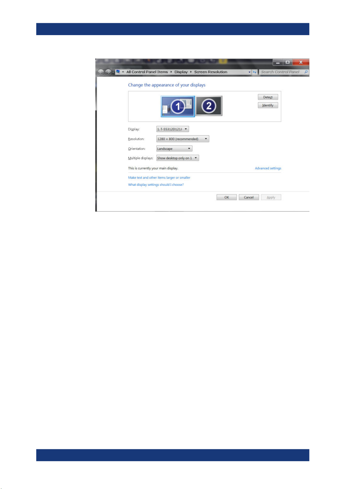
the external monitor is a duplicate of the instrument's monitor.
If you configure the external monitor to be used as the only display in the Windows
configuration dialog box ("Show only on 2"), the maximum screen resolution of the
monitor is used. In this case, you can maximize the R&S FSWP application window
and see even more details. You cannot change the monitor's screen resolution via the
standard Windows configuration dialog box.
However, you can restore the default instrument resolution (1280x800) on the monitor
using the instrument function "Setup" > "Display" > "Configure Monitor" > "Screen Resolution: Restore to default".
The R&S FSWP supports a minimum resolution of 1280x768 pixels.
1. Connect the external monitor to the R&S FSWP.
2. Press the [Setup] key.
3. Press the "Display" softkey.
4. Select the "Configure Monitor" tab in the "Display" dialog box.
The standard Windows "Screen Resolution" dialog box is displayed.
27User Manual 1177.5633.02 ─ 13
R&S®FSWP
Preparing for Use
Windows Operating System
5. Select the instrument for display:
● "Display 1" : internal monitor only
● "Display 2" : external monitor only
● "Duplicate" : both internal and external monitor
6. Tap "Apply" to try out the settings before they are accepted permanently, then you
can easily return to the previous settings, if necessary.
7. Select "OK" if the settings are suitable.
3.10 Windows Operating System
The instrument contains the Microsoft Windows operating system which has been configured according to the instrument's features and needs. Changes in the system setup
are only required when peripherals like a keyboard or a printer are installed or if the
network configuration does not comply with the default settings. After the R&S FSWP
is started, the operating system boots and the instrument firmware is started automatically.
Tested software
The drivers and programs used on the instrument under Microsoft Windows are adapted to the instrument. Only install update software released by Rohde & Schwarz to
modify existing instrument software.
28User Manual 1177.5633.02 ─ 13

R&S®FSWP
Preparing for Use
Windows Operating System
You can install additional software on the instrument; however, additional software can
impair instrument function. Thus, run only programs that Rohde & Schwarz has tested
for compatibility with the instrument software.
The following program packages have been tested:
●
Symantec Endpoint Security – virus-protection software
●
FileShredder - for reliable deletion of files on the hard disk
Service packs and updates
Microsoft regularly creates security updates and other patches to protect Windowsbased operating systems. These are released through the Microsoft Update website
and associated update server. Instruments using Windows, especially those that connect to a network, should be updated regularly.
Firewall settings
A firewall protects an instrument by preventing unauthorized users from gaining access
to it through a network. Rohde & Schwarz highly recommends the use of the firewall on
your instrument. Rohde & Schwarz instruments are shipped with the Windows firewall
enabled and preconfigured in such a way that all ports and connections for remote
control are enabled.
Note that changing firewall settings requires administrator rights.
Virus protection
Take appropriate steps to protect your instruments from infection. Use strong firewall
settings and scan any removable storage device used with a Rohde & Schwarz instrument regularly. It is also recommended that you install anti-virus software on the instrument. Rohde & Schwarz does NOT recommend running anti-virus software in the
background ("on-access" mode) on Windows-based instruments, due to potentially
degrading instrument performance. However, Rohde & Schwarz does recommend running it during non-critical hours.
For details and recommendations, see the following Rohde & Schwarz white paper:
●
1EF96: Malware Protection Windows 10
To access the "Start" menu
The Windows "Start" menu provides access to the Microsoft Windows functionality and
installed programs.
► Select the "Windows" icon in the toolbar, or press the "Windows" key or the [CTRL
+ ESC] key combination on the (external) keyboard.
The "Start" menu and the Windows taskbar are displayed.
29User Manual 1177.5633.02 ─ 13

R&S®FSWP
3.11 Logging On
Preparing for Use
Logging On
The Windows taskbar also provides quick access to commonly used programs, for
example Paint or WordPad. IECWIN, the auxiliary remote control tool provided free of
charge and installed by Rohde & Schwarz, is also available from the taskbar or "Start"
menu.
For details on the IECWIN tool, see the "Network and Remote Control" chapter of the
R&S FSWP user manual.
All necessary system settings can be defined in the "Start > Settings" menu.
For required settings, refer to the Microsoft Windows documentation and to the hardware description.
Microsoft Windows requires that users identify themselves by entering a user name
and password in a login window. By default, the R&S FSWP provides two user
accounts:
●
"Instrument": a standard user account with limited access
●
"Admin" or "Administrator" (depends on firmware image): an administrator
account with unrestricted access to the computer/domain
Some administrative tasks require administrator rights (e.g. the configuration of a LAN
network). Refer to the description of the basic instrument Setup ([Setup] menu) to find
out which functions are affected.
Passwords
For all default user accounts, the initial password is 894129. Note that this password is
very weak, and it is recommended that you change the password for both users after
initial login. An administrator can change the password in Microsoft Windows for any
user at any time via "Start > Settings > Account > SignIn Options > Password >
Change".
Auto-login
When shipped, the instrument automatically logs on the default "Instrument" user to
Microsoft Windows using the default password. This function is active until an administrator explicitly deactivates it or changes the password.
Changing the password and use of auto-login function
Note that when you change the default password, the default auto-login function no
longer works!
In this case, you must enter the new password manually to log on.
30User Manual 1177.5633.02 ─ 13
 Loading...