

Rohde&Schwarz R&S®FSV-K10x LTE UL User Manual
R&S®FSV-K10x (LTE Uplink)
LTE Uplink Measurement Application
User Manual
(;ÚÚÜ2)
1176767802
User Manual
Version 06

This manual describes the following firmware applications:
●
R&S®FSV-K101 EUTRA / LTE FDD Uplink Measurement Application (1310.9100.02)
●
R&S®FSV-K105 EUTRA / LTE TDD Uplink Measurement Application (1310.9780.02)
This manual describes the following R&S FSVA/FSV models with firmware version 3.30 and higher:
●
R&S®FSVA4 (1321.3008K05)
●
R&S®FSVA7 (1321.3008K08)
●
R&S®FSVA13 (1321.3008K14)
●
R&S®FSVA30 (1321.3008K31)
●
R&S®FSVA40 (1321.3008K41)
●
R&S®FSV4 (1321.3008K04)
●
R&S®FSV7 (1321.3008K07)
●
R&S®FSV13 (1321.3008K13)
●
R&S®FSV30 (1321.3008K30)
●
R&S®FSV40 (1321.3008K39/1321.3008K40)
It also applies to the following R&S®FSV models. However, note the differences described in Chapter 1.4,
"Notes for Users of R&S FSV 1307.9002Kxx Models", on page 13.
●
R&S®FSV3 (1307.9002K03)
●
R&S®FSV7 (1307.9002K07)
●
R&S®FSV13 (1307.9002K13)
●
R&S®FSV30 (1307.9002K30)
●
R&S®FSV40 (1307.9002K39/1307.9002K40)
© 2019 Rohde & Schwarz GmbH & Co. KG
Mühldorfstr. 15, 81671 München, Germany
Phone: +49 89 41 29 - 0
Fax: +49 89 41 29 12 164
Email: info@rohde-schwarz.com
Internet: www.rohde-schwarz.com
Subject to change – Data without tolerance limits is not binding.
R&S® is a registered trademark of Rohde & Schwarz GmbH & Co. KG.
Trade names are trademarks of the owners.
1176.7678.02 | Version 06 | R&S®FSV-K10x (LTE Uplink)
The following abbreviations are used throughout this manual: R&S®FSV/FSVA is abbreviated as R&S FSV/FSVA.

R&S®FSV-K10x (LTE Uplink)
Contents
1 Preface.................................................................................................... 9
1.1 Documentation Overview............................................................................................. 9
1.1.1 Quick Start Guide............................................................................................................9
1.1.2 Operating Manuals and Help.......................................................................................... 9
1.1.3 Service Manual............................................................................................................... 9
1.1.4 Instrument Security Procedures....................................................................................10
1.1.5 Basic Safety Instructions...............................................................................................10
1.1.6 Data Sheets and Brochures.......................................................................................... 10
1.1.7 Release Notes and Open Source Acknowledgment (OSA).......................................... 10
1.1.8 Application Notes, Application Cards, White Papers, etc..............................................10
1.2 Conventions Used in the Documentation.................................................................10
Contents
1.2.1 Typographical Conventions...........................................................................................10
1.2.2 Conventions for Procedure Descriptions.......................................................................11
1.2.3 Notes on Screenshots................................................................................................... 11
1.3 How to Use the Help System......................................................................................11
1.4 Notes for Users of R&S FSV 1307.9002Kxx Models................................................ 13
2 Introduction.......................................................................................... 14
2.1 Requirements for UMTS Long-Term Evolution........................................................ 14
2.2 Long-Term Evolution Uplink Transmission Scheme............................................... 16
2.2.1 SC-FDMA......................................................................................................................16
2.2.2 SC-FDMA Parameterization..........................................................................................17
2.2.3 Uplink Data Transmission............................................................................................. 17
2.2.4 Uplink Reference Signal Structure................................................................................ 18
2.2.5 Uplink Physical Layer Procedures................................................................................ 18
2.3 References...................................................................................................................20
3 Welcome............................................................................................... 21
3.1 Installing the Software................................................................................................21
3.2 Application Overview..................................................................................................21
3.3 Support........................................................................................................................ 23
4 Measurement Basics........................................................................... 24
3User Manual 1176.7678.02 ─ 06

R&S®FSV-K10x (LTE Uplink)
4.1 Symbols and Variables...............................................................................................24
4.2 Overview...................................................................................................................... 25
4.3 The LTE Uplink Analysis Measurement Application................................................25
4.3.1 Synchronization.............................................................................................................26
4.3.2 Analysis.........................................................................................................................27
4.4 SRS EVM Calculation..................................................................................................29
5 Measurements and Result Displays...................................................31
5.1 Numerical Results.......................................................................................................31
5.2 Measuring the Power Over Time................................................................................34
5.3 Measuring the Error Vector Magnitude (EVM)..........................................................36
5.4 Measuring the Spectrum............................................................................................ 38
5.4.1 Frequency Sweep Measurements................................................................................ 38
Contents
5.4.2 I/Q Measurements.........................................................................................................42
5.5 Measuring the Symbol Constellation........................................................................ 44
5.6 Measuring Statistics................................................................................................... 45
5.7 3GPP Test Scenarios.................................................................................................. 48
6 Configuring and Performing the Measurement.................................49
6.1 Performing Measurements.........................................................................................49
6.2 Defining General Measurement Characteristics...................................................... 50
6.2.1 Defining Signal Characteristics..................................................................................... 50
6.2.2 Configuring the Input Level........................................................................................... 52
6.2.3 Configuring the Data Capture....................................................................................... 54
6.2.4 Triggering Measurements............................................................................................. 55
6.3 Configuring Spectrum Measurements...................................................................... 57
6.3.1 General ACLR and SEM Configuration.........................................................................57
6.3.2 Configuring SEM Measurements.................................................................................. 58
6.3.3 Configuring ACLR Measurements................................................................................ 59
6.4 Defining Advanced Measurement Characteristics.................................................. 60
6.4.1 Controlling I/Q Data.......................................................................................................60
6.4.2 Controlling the Input...................................................................................................... 61
6.4.3 Configuring the Digital I/Q Input.................................................................................... 62
6.5 Configuring the Signal Demodulation.......................................................................63
6.5.1 Configuring the Data Analysis.......................................................................................63
4User Manual 1176.7678.02 ─ 06

R&S®FSV-K10x (LTE Uplink)
6.5.2 Compensating Measurement Errors............................................................................. 65
6.6 Configuring Uplink Frames........................................................................................ 66
6.6.1 Configuring TDD Signals...............................................................................................66
6.6.2 Configuring the Physical Layer Cell Identity..................................................................68
6.6.3 Subframe Configuration................................................................................................ 69
6.7 Defining Advanced Signal Characteristics...............................................................71
6.7.1 Configuring the Demodulation Reference Signal.......................................................... 71
6.7.2 Configuring the Sounding Reference Signal................................................................. 73
6.7.3 Defining the PUSCH Structure......................................................................................76
6.7.4 Defining the PUCCH Structure......................................................................................77
6.7.5 Defining Global Signal Characteristics..........................................................................79
6.8 Defining the PRACH Structure...................................................................................79
Contents
7 Analysis................................................................................................ 82
7.1 Signal Part Selection.................................................................................................. 82
7.2 Measurement Units..................................................................................................... 84
7.3 Miscellaneous Analysis..............................................................................................84
7.4 Constellation Diagram Filter...................................................................................... 85
7.5 Y-Axis Scale.................................................................................................................85
7.6 Markers........................................................................................................................ 86
8 File Management..................................................................................89
8.1 File Manager................................................................................................................ 89
8.2 SAVE/RECALL Key......................................................................................................90
9 Remote Commands............................................................................. 91
9.1 Common Suffixes........................................................................................................91
9.2 Introduction................................................................................................................. 92
9.2.1 Conventions used in Descriptions.................................................................................92
9.2.2 Long and Short Form.................................................................................................... 93
9.2.3 Numeric Suffixes........................................................................................................... 93
9.2.4 Optional Keywords........................................................................................................ 93
9.2.5 Alternative Keywords.................................................................................................... 94
9.2.6 SCPI Parameters.......................................................................................................... 94
9.3 General Configuration................................................................................................ 96
5User Manual 1176.7678.02 ─ 06

R&S®FSV-K10x (LTE Uplink)
9.4 Measurement Control................................................................................................. 99
9.5 Numeric Result Query.............................................................................................. 100
9.6 Measurement Result Query......................................................................................110
9.6.1 Using the TRACe[:DATA] Command...........................................................................110
9.6.2 Reading Results..........................................................................................................120
9.7 General Settings........................................................................................................123
9.7.1 Defining Signal Characteristics................................................................................... 123
9.7.2 Configuring the Input Level......................................................................................... 125
9.7.3 Configuring the Data Capture..................................................................................... 128
9.8 Advanced Settings....................................................................................................129
9.8.1 Controlling I/Q Data.....................................................................................................130
9.8.2 Controlling the Input.................................................................................................... 130
9.8.3 Configuring the Digital I/Q Input.................................................................................. 131
Contents
9.9 Trigger Configuration............................................................................................... 132
9.10 Spectrum Measurements......................................................................................... 135
9.11 Signal Demodulation................................................................................................ 139
9.11.1 Configuring the Data Analysis.....................................................................................139
9.11.2 Compensating Measurement Errors........................................................................... 142
9.12 Frame Configuration.................................................................................................142
9.12.1 Configuring TDD Signals.............................................................................................142
9.12.2 Configuring the Physical Layer Cell Identity................................................................143
9.12.3 Configuring Subframes............................................................................................... 145
9.13 Advanced Signal Characteristics............................................................................ 147
9.13.1 Configuring the Demodulation Reference Signal........................................................ 147
9.13.2 Configuring the Sounding Reference Signal............................................................... 149
9.13.3 Defining the PUSCH Structure....................................................................................152
9.13.4 Defining the PUCCH Structure....................................................................................154
9.13.5 Defining Global Signal Characteristics........................................................................156
9.14 PRACH Structure...................................................................................................... 156
9.15 Measurement Result Analysis................................................................................. 159
9.15.1 Selecting Displayed Data............................................................................................ 159
9.15.2 Selecting Units............................................................................................................ 162
9.15.3 Using Markers............................................................................................................. 163
6User Manual 1176.7678.02 ─ 06

R&S®FSV-K10x (LTE Uplink)
9.15.4 Using Delta Markers....................................................................................................166
9.15.5 Scaling the Vertical Diagram Axis............................................................................... 168
List of Commands..............................................................................170
Index....................................................................................................174
Contents
7User Manual 1176.7678.02 ─ 06

R&S®FSV-K10x (LTE Uplink)
Contents
8User Manual 1176.7678.02 ─ 06

R&S®FSV-K10x (LTE Uplink)
1 Preface
1.1 Documentation Overview
This section provides an overview of the R&S FSVA/FSV user documentation. Unless
specified otherwise, you find the documents on the R&S FSVA/FSV product page at:
www.rohde-schwarz.com/manual/FSVA
1.1.1 Quick Start Guide
Introduces the R&S FSVA/FSV and describes how to set up and start working with the
product. Includes basic operations, typical measurement examples, and general information, e.g. safety instructions, etc. A printed version is delivered with the instrument.
A PDF version is available for download on the Internet.
Preface
Documentation Overview
1.1.2 Operating Manuals and Help
Separate operating manuals are provided for the base unit and the firmware applications:
●
Base unit manual
Contains the description of all instrument modes and functions. It also provides an
introduction to remote control, a complete description of the remote control commands with programming examples, and information on maintenance, instrument
interfaces and error messages. Includes the contents of the getting started manual.
●
Firmware application manual
Contains the description of the specific functions of a firmware application. Basic
information on operating the R&S FSVA/FSV is not included.
The contents of the operating manuals are available as help in the R&S FSVA/FSV.
The help offers quick, context-sensitive access to the complete information for the
base unit and the firmware applications.
All operating manuals are also available for download or for immediate display on the
Internet.
1.1.3 Service Manual
Describes the performance test for checking the rated specifications, module replacement and repair, firmware update, troubleshooting and fault elimination, and contains
mechanical drawings and spare part lists.
The service manual is available for registered users on the global Rohde & Schwarz
information system (GLORIS, https://gloris.rohde-schwarz.com).
9User Manual 1176.7678.02 ─ 06

R&S®FSV-K10x (LTE Uplink)
1.1.4 Instrument Security Procedures
Deals with security issues when working with the R&S FSVA/FSV in secure areas. It is
available for download on the Internet.
1.1.5 Basic Safety Instructions
Contains safety instructions, operating conditions and further important information.
The printed document is delivered with the instrument.
1.1.6 Data Sheets and Brochures
The data sheet contains the technical specifications of the R&S FSVA/FSV. It also lists
the firmware applications and their order numbers, and optional accessories.
The brochure provides an overview of the instrument and deals with the specific characteristics.
Preface
Conventions Used in the Documentation
See www.rohde-schwarz.com/brochure-datasheet/FSV
1.1.7 Release Notes and Open Source Acknowledgment (OSA)
The release notes list new features, improvements and known issues of the current
firmware version, and describe the firmware installation.
The open source acknowledgment document provides verbatim license texts of the
used open source software.
See www.rohde-schwarz.com/firmware/FSV
1.1.8 Application Notes, Application Cards, White Papers, etc.
These documents deal with special applications or background information on particular topics.
See www.rohde-schwarz.com/application/FSV
1.2 Conventions Used in the Documentation
1.2.1 Typographical Conventions
The following text markers are used throughout this documentation:
10User Manual 1176.7678.02 ─ 06
R&S®FSV-K10x (LTE Uplink)
Convention Description
Preface
How to Use the Help System
"Graphical user interface elements"
[Keys] Key and knob names are enclosed by square brackets.
Filenames, commands,
program code
Input Input to be entered by the user is displayed in italics.
Links Links that you can click are displayed in blue font.
"References" References to other parts of the documentation are enclosed by quota-
All names of graphical user interface elements on the screen, such as
dialog boxes, menus, options, buttons, and softkeys are enclosed by
quotation marks.
Filenames, commands, coding samples and screen output are distinguished by their font.
tion marks.
1.2.2 Conventions for Procedure Descriptions
When operating the instrument, several alternative methods may be available to perform the same task. In this case, the procedure using the touchscreen is described.
Any elements that can be activated by touching can also be clicked using an additionally connected mouse. The alternative procedure using the keys on the instrument or
the on-screen keyboard is only described if it deviates from the standard operating procedures.
The term "select" may refer to any of the described methods, i.e. using a finger on the
touchscreen, a mouse pointer in the display, or a key on the instrument or on a keyboard.
1.2.3 Notes on Screenshots
When describing the functions of the product, we use sample screenshots. These
screenshots are meant to illustrate as many as possible of the provided functions and
possible interdependencies between parameters. The shown values may not represent
realistic usage scenarios.
The screenshots usually show a fully equipped product, that is: with all options installed. Thus, some functions shown in the screenshots may not be available in your particular product configuration.
1.3 How to Use the Help System
Calling context-sensitive and general help
► To display the general help dialog box, press the [HELP] key on the front panel.
The help dialog box "View" tab is displayed. A topic containing information about
the current menu or the currently opened dialog box and its function is displayed.
11User Manual 1176.7678.02 ─ 06

R&S®FSV-K10x (LTE Uplink)
For standard Windows dialog boxes (e.g. File Properties, Print dialog etc.), no contextsensitive help is available.
► If the help is already displayed, press the softkey for which you want to display
help.
A topic containing information about the softkey and its function is displayed.
If a softkey opens a submenu and you press the softkey a second time, the submenu
of the softkey is displayed.
Contents of the help dialog box
The help dialog box contains four tabs:
●
"Contents" - contains a table of help contents
●
"View" - contains a specific help topic
●
"Index" - contains index entries to search for help topics
●
"Zoom" - contains zoom functions for the help display
Preface
How to Use the Help System
To change between these tabs, press the tab on the touchscreen.
Navigating in the table of contents
●
To move through the displayed contents entries, use the [UP ARROW] and [DOWN
ARROW] keys. Entries that contain further entries are marked with a plus sign.
●
To display a help topic, press the [ENTER] key. The "View" tab with the corresponding help topic is displayed.
●
To change to the next tab, press the tab on the touchscreen.
Navigating in the help topics
●
To scroll through a page, use the rotary knob or the [UP ARROW] and [DOWN
ARROW] keys.
●
To jump to the linked topic, press the link text on the touchscreen.
Searching for a topic
1. Change to the "Index" tab.
2. Enter the first characters of the topic you are interested in. The entries starting with
these characters are displayed.
3. Change the focus by pressing the [ENTER] key.
4. Select the suitable keyword by using the [UP ARROW] or [DOWN ARROW] keys
or the rotary knob.
5. Press the [ENTER] key to display the help topic.
The "View" tab with the corresponding help topic is displayed.
12User Manual 1176.7678.02 ─ 06

R&S®FSV-K10x (LTE Uplink)
Changing the zoom
1. Change to the "Zoom" tab.
2. Set the zoom using the rotary knob. Four settings are available: 1-4. The smallest
size is selected by number 1, the largest size is selected by number 4.
Closing the help window
► Press the [ESC] key or a function key on the front panel.
1.4 Notes for Users of R&S FSV 1307.9002Kxx Models
Users of R&S FSV 1307.9002Kxx models should consider the following differences to
the description of the newer R&S FSVA/FSV 1321.3008Kxx models:
●
Functions that are based on the Windows 10 operating system (e.g. printing or setting up networks) may have a slightly different appearance or require different settings on the Windows XP based models. For such functions, refer to the Windows
documentation or the documentation originally provided with the R&S FSV instrument.
●
The R&S FSV 1307.9002K03 model is restricted to a maximum frequency of
3 GHz, whereas the R&S FSVA/FSV1321.3008K04 model has a maximum frequency of 4 GHz.
●
The bandwidth extension option R&S FSV-B160 (1311.2015.xx) is not available for
the R&S FSV 1307.9002Kxx models. The maximum usable I/Q analysis bandwidth
for these models is 28 MHz, or with option R&S FSV-B70, 40 MHz.
Preface
Notes for Users of R&S FSV 1307.9002Kxx Models
13User Manual 1176.7678.02 ─ 06

R&S®FSV-K10x (LTE Uplink)
2 Introduction
Currently, UMTS networks worldwide are being upgraded to high speed downlink
packet access (HSDPA) in order to increase data rate and capacity for downlink packet
data. In the next step, high speed uplink packet access (HSUPA) will boost uplink performance in UMTS networks. While HSDPA was introduced as a 3GPP Release 5 feature, HSUPA is an important feature of 3GPP Release 6. The combination of HSDPA
and HSUPA is often referred to as HSPA.
However, even with the introduction of HSPA, the evolution of UMTS has not reached
its end. HSPA+ will bring significant enhancements in 3GPP Release 7. The objective
is to enhance the performance of HSPA-based radio networks in terms of spectrum
efficiency, peak data rate and latency, and to exploit the full potential of WCDMAbased
5 MHz operation. Important features of HSPA+ are downlink multiple input multiple output (MIMO), higher order modulation for uplink and downlink, improvements of layer 2
protocols, and continuous packet connectivity.
In order to ensure the competitiveness of UMTS for the next 10 years and beyond,
concepts for UMTS long term evolution (LTE) have been investigated. The objective is
a high-data-rate, low-latency and packet-optimized radio access technology. Therefore,
a study item was launched in 3GPP Release 7 on evolved UMTS terrestrial radio
access (EUTRA) and evolved UMTS terrestrial radio access network (EUTRAN). LTE/
EUTRA will then form part of 3GPP Release 8 core specifications.
Introduction
Requirements for UMTS Long-Term Evolution
This introduction focuses on LTE/EUTRA technology. In the following, the terms LTE or
EUTRA are used interchangeably.
In the context of the LTE study item, 3GPP work first focused on the definition of
requirements, e.g. targets for data rate, capacity, spectrum efficiency, and latency. Also
commercial aspects such as costs for installing and operating the network were considered. Based on these requirements, technical concepts for the air interface transmission schemes and protocols were studied. Notably, LTE uses new multiple access
schemes on the air interface: orthogonal frequency division multiple access (OFDMA)
in downlink and single carrier frequency division multiple access (SC-FDMA) in uplink.
Furthermore, MIMO antenna schemes form an essential part of LTE. In an attempt to
simplify protocol architecture, LTE brings some major changes to the existing UMTS
protocol concepts. Impact on the overall network architecture including the core network is being investigated in the context of 3GPP system architecture evolution (SAE).
● Requirements for UMTS Long-Term Evolution....................................................... 14
● Long-Term Evolution Uplink Transmission Scheme................................................16
● References..............................................................................................................20
2.1 Requirements for UMTS Long-Term Evolution
LTE is focusing on optimum support of packet switched (PS) services. Main requirements for the design of an LTE system are documented in 3GPP TR 25.913 [1] and
can be summarized as follows:
14User Manual 1176.7678.02 ─ 06

R&S®FSV-K10x (LTE Uplink)
●
Data Rate: Peak data rates target 100 Mbps (downlink) and 50 Mbps (uplink) for
20 MHz spectrum allocation, assuming two receive antennas and one transmit
antenna are at the terminal.
●
Throughput: The target for downlink average user throughput per MHz is three to
four times better than Release 6. The target for uplink average user throughput per
MHz is two to three times better than Release 6.
●
Spectrum efficiency: The downlink target is three to four times better than Release
6. The uplink target is two to three times better than Release 6.
●
Latency: The one-way transit time between a packet being available at the IP layer
in either the UE or radio access network and the availability of this packet at IP
layer in the radio access network/UE shall be less than 5 ms. Also C-plane latency
shall be reduced, e.g. to allow fast transition times of less than 100 ms from
camped state to active state.
●
Bandwidth: Scaleable bandwidths of 5 MHz, 10 MHz, 15 MHz, and 20 MHz shall
be supported. Also bandwidths smaller than 5 MHz shall be supported for more
flexibility.
●
Interworking: Interworking with existing UTRAN/GERAN systems and non-3GPP
systems shall be ensured. Multimode terminals shall support handover to and from
UTRAN and GERAN as well as inter-RAT measurements. Interruption time for
handover between EUTRAN and UTRAN/GERAN shall be less than 300 ms for
realtime services and less than 500 ms for non-realtime services.
●
Multimedia broadcast multicast services (MBMS): MBMS shall be further enhanced
and is then referred to as E-MBMS.
●
Costs: Reduced CAPEX and OPEX including backhaul shall be achieved. Costeffective migration from Release 6 UTRA radio interface and architecture shall be
possible. Reasonable system and terminal complexity, cost, and power consumption shall be ensured. All the interfaces specified shall be open for multivendor
equipment interoperability.
●
Mobility: The system should be optimized for low mobile speed (0 to 15 km/h), but
higher mobile speeds shall be supported as well, including high speed train environment as a special case.
●
Spectrum allocation: Operation in paired (frequency division duplex / FDD mode)
and unpaired spectrum (time division duplex / TDD mode) is possible.
●
Co-existence: Co-existence in the same geographical area and co-location with
GERAN/UTRAN shall be ensured. Also, co-existence between operators in adjacent bands as well as cross-border co-existence is a requirement.
●
Quality of Service: End-to-end quality of service (QoS) shall be supported. VoIP
should be supported with at least as good radio and backhaul efficiency and
latency as voice traffic over the UMTS circuit switched networks.
●
Network synchronization: Time synchronization of different network sites shall not
be mandated.
Introduction
Requirements for UMTS Long-Term Evolution
15User Manual 1176.7678.02 ─ 06
R&S®FSV-K10x (LTE Uplink)
2.2 Long-Term Evolution Uplink Transmission Scheme
2.2.1 SC-FDMA
During the study item phase of LTE, alternatives for the optimum uplink transmission
scheme were investigated. While OFDMA is seen optimum to fulfil the LTE requirements in downlink, OFDMA properties are less favourable for the uplink. This is mainly
due to weaker peak-to-average power ratio (PAPR) properties of an OFDMA signal,
resulting in worse uplink coverage.
Thus, the LTE uplink transmission scheme for FDD and TDD mode is based on
SCFDMA with a cyclic prefix. SC-FDMA signals have better PAPR properties compared to an OFDMA signal. This was one of the main reasons for selecting SC-FDMA
as LTE uplink access scheme. The PAPR characteristics are important for cost-effective design of UE power amplifiers. Still, SC-FDMA signal processing has some similarities with OFDMA signal processing, so parameterization of downlink and uplink can be
harmonized.
Introduction
Long-Term Evolution Uplink Transmission Scheme
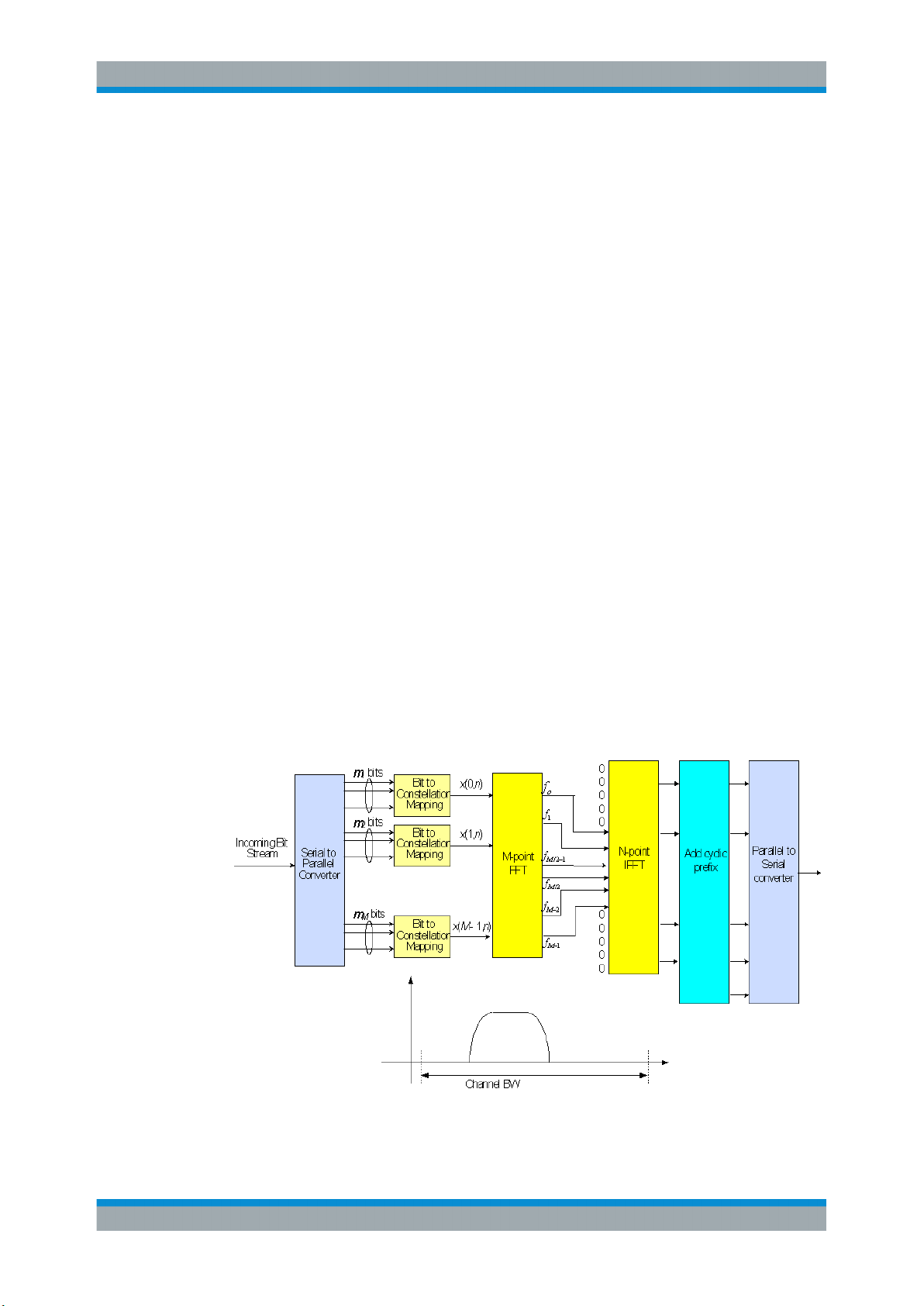
There are different possibilities how to generate an SC-FDMA signal. DFT-spreadOFDM (DFT-s-OFDM) has been selected for EUTRA. The principle is illustrated in Fig-
ure 2-1.
For DFT-s-OFDM, a size-M DFT is first applied to a block of M modulation symbols.
QPSK, 16QAM and 64 QAM are used as uplink EUTRA modulation schemes, the latter being optional for the UE. The DFT transforms the modulation symbols into the frequency domain. The result is mapped onto the available sub-carriers. In EUTRA
uplink, only localized transmission on consecutive sub-carriers is allowed. An N point
IFFT where N>M is then performed as in OFDM, followed by addition of the cyclic prefix and parallel to serial conversion.
Figure 2-1: Block Diagram of DFT-s-OFDM (Localized Transmission)
16User Manual 1176.7678.02 ─ 06

R&S®FSV-K10x (LTE Uplink)
The DFT processing is therefore the fundamental difference between SC-FDMA and
OFDMA signal generation. This is indicated by the term DFT-spread-OFDM. In an
SCFDMA signal, each sub-carrier used for transmission contains information of all
transmitted modulation symbols, since the input data stream has been spread by the
DFT transform over the available sub-carriers. In contrast to this, each sub-carrier of
an OFDMA signal only carries information related to specific modulation symbols.
2.2.2 SC-FDMA Parameterization
The EUTRA uplink structure is similar to the downlink. An uplink radio frame consists
of 20 slots of 0.5 ms each, and 1 subframe consists of 2 slots. The slot structure is
shown in Figure 2-2.
Introduction
Long-Term Evolution Uplink Transmission Scheme
Each slot carries
= 6 for the extended cyclic prefix. SC-FDMA symbol number 3 (i.e. the 4th symbol
in a slot) carries the reference signal for channel demodulation.
Figure 2-2: Uplink Slot Structure
Also for the uplink, a bandwidth agnostic layer 1 specification has been selected. The
table below shows the configuration parameters in an overview table.
SC-FDMA symbols, where = 7 for the normal cyclic prefix and
2.2.3 Uplink Data Transmission
In uplink, data is allocated in multiples of one resource block. Uplink resource block
size in the frequency domain is 12 sub-carriers, i.e. the same as in downlink. However,
not all integer multiples are allowed in order to simplify the DFT design in uplink signal
processing. Only factors 2, 3, and 5 are allowed.
The uplink transmission time interval (TTI) is 1 ms (same as downlink).
17User Manual 1176.7678.02 ─ 06

R&S®FSV-K10x (LTE Uplink)
User data is carried on the Physical Uplink Shared Channel (PUSCH) that is determined by the transmission bandwidth NTx and the frequency hopping pattern k0.
The Physical Uplink Control Channel (PUCCH) carries uplink control information, e.g.
CQI reports and ACK/NACK information related to data packets received in the downlink. The PUCCH is transmitted on a reserved frequency region in the uplink.
2.2.4 Uplink Reference Signal Structure
Uplink reference signals are used for two different purposes: on the one hand, they are
used for channel estimation in the eNodeB receiver in order to demodulate control and
data channels. On the other hand, the reference signals provide channel quality information as a basis for scheduling decisions in the base station. The latter purpose is
also called channel sounding.
The uplink reference signals are based on CAZAC (Constant Amplitude Zero AutoCorrelation) sequences.
Introduction
Long-Term Evolution Uplink Transmission Scheme
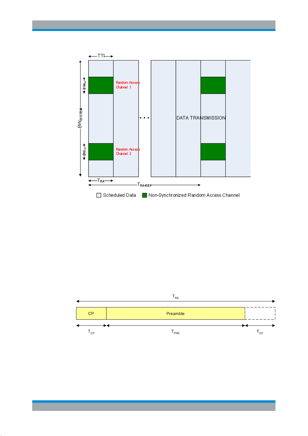
2.2.5 Uplink Physical Layer Procedures
For EUTRA, the following uplink physical layer procedures are especially important:
Non-synchronized random access
Random access may be used to request initial access, as part of handover, when transiting from idle to connected, or to re-establish uplink synchronization. The structure is
shown in Figure 2-3.
18User Manual 1176.7678.02 ─ 06
R&S®FSV-K10x (LTE Uplink)
Introduction
Long-Term Evolution Uplink Transmission Scheme
Figure 2-3: Random Access Structure, principle
Multiple random access channels may be defined in the frequency domain within one
access period TRA in order to provide a sufficient number of random access opportuni-
ties.
For random access, a preamble is defined as shown in Figure 2-4. The preamble
sequence occupies T
= 0.8 ms and the cyclic prefix occupies TCP = 0.1 ms within
PRE
one subframe of 1 ms. During the guard time TGT, nothing is transmitted. The preamble
bandwidth is 1.08 MHz (72 sub-carriers). Higher layer signalling controls in which sub-
frames the preamble transmission is allowed, and the location in the frequency
domain. Per cell, there are 64 random access preambles. They are generated from
Zadoff-Chu sequences.
Figure 2-4: Random Access Preamble
The random access procedure uses open loop power control with power ramping similar to WCDMA. After sending the preamble on a selected random access channel, the
UE waits for the random access response message. If no response is detected then
another random access channel is selected and a preamble is sent again.
19User Manual 1176.7678.02 ─ 06

R&S®FSV-K10x (LTE Uplink)
Uplink scheduling
Scheduling of uplink resources is done by eNodeB. The eNodeB assigns certain time/
frequency resources to the UEs and informs UEs about transmission formats to use.
Scheduling decisions affecting the uplink are communicated to the UEs via the Physical Downlink Control Channel (PDCCH) in the downlink. The scheduling decisions may
be based on QoS parameters, UE buffer status, uplink channel quality measurements,
UE capabilities, UE measurement gaps, etc.
Uplink link adaptation
As uplink link adaptation methods, transmission power control, adaptive modulation
and channel coding rate, as well as adaptive transmission bandwidth can be used.
Uplink timing control
Uplink timing control is needed to time align the transmissions from different UEs with
the receiver window of the eNodeB. The eNodeB sends the appropriate timing-control
commands to the UEs in the downlink, commanding them to adapt their respective
transmit timing.
Introduction
References
Hybrid automatic repeat request (ARQ)
The Uplink Hybrid ARQ protocol is already known from HSUPA. The eNodeB has the
capability to request retransmissions of incorrectly received data packets.
2.3 References
[1] 3GPP TS 25.913: Requirements for E-UTRA and E-UTRAN (Release 7)
[2] 3GPP TR 25.892: Feasibility Study for Orthogonal Frequency Division Multiplexing
(OFDM) for UTRAN enhancement (Release 6)
[3] 3GPP TS 36.211 v8.3.0: Physical Channels and Modulation (Release 8)
[4] 3GPP TS 36.300: E-UTRA and E-UTRAN; Overall Description; Stage 2 (Release 8)
[5] 3GPP TS 22.978: All-IP Network (AIPN) feasibility study (Release 7)
[6] 3GPP TS 25.213: Spreading and modulation (FDD)
[7] Speth, M., Fechtel, S., Fock, G., and Meyr, H.: Optimum Receiver Design for Wireless Broad-Band Systems Using OFDM – Part I. IEEE Trans. on Commun. Vol. 47
(1999) No. 11, pp. 1668-1677.
[8] Speth, M., Fechtel, S., Fock, G., and Meyr, H.: Optimum Receiver Design for
OFDM-Based Broadband Transmission – Part II: A Case Study. IEEE Trans. on Commun. Vol. 49 (2001) No. 4, pp. 571-578.
20User Manual 1176.7678.02 ─ 06

R&S®FSV-K10x (LTE Uplink)
3 Welcome
The LTE measurement application uses the I/Q capture functionality of the following
spectrum and signal analyzers to enable LTE TX measurements conforming to the
3GPP specification.
●
R&S FSV
This manual contains all information necessary to configure, perform and analyze such
measurements.
● Installing the Software.............................................................................................21
● Application Overview...............................................................................................21
● Support....................................................................................................................23
3.1 Installing the Software
Welcome
Application Overview
For information on the installation procedure see the release notes of the R&S FSVA/
FSV.
3.2 Application Overview
Starting the application
Access the application via the "Mode" menu.
► Press the [MODE] key and select "LTE".
Note that you may have to browse through the "Mode" menu with the "More" softkey to find the LTE entry.
Second LTE channel
The application provides a second LTE channel that you can access via the Mode
menu with the softkey labeled "LTE2".
This second channel has the same functionality as the LTE channel. You can use it to
perform measurements on two LTE channels with a different configuration, for example
to test carrier aggregation.
Presetting the software
When you first start the software, all settings are in their default state. After you have
changed any parameter, you can restore the default state with the [PRESET] key.
CONFigure:PRESet on page 98
21User Manual 1176.7678.02 ─ 06
R&S®FSV-K10x (LTE Uplink)
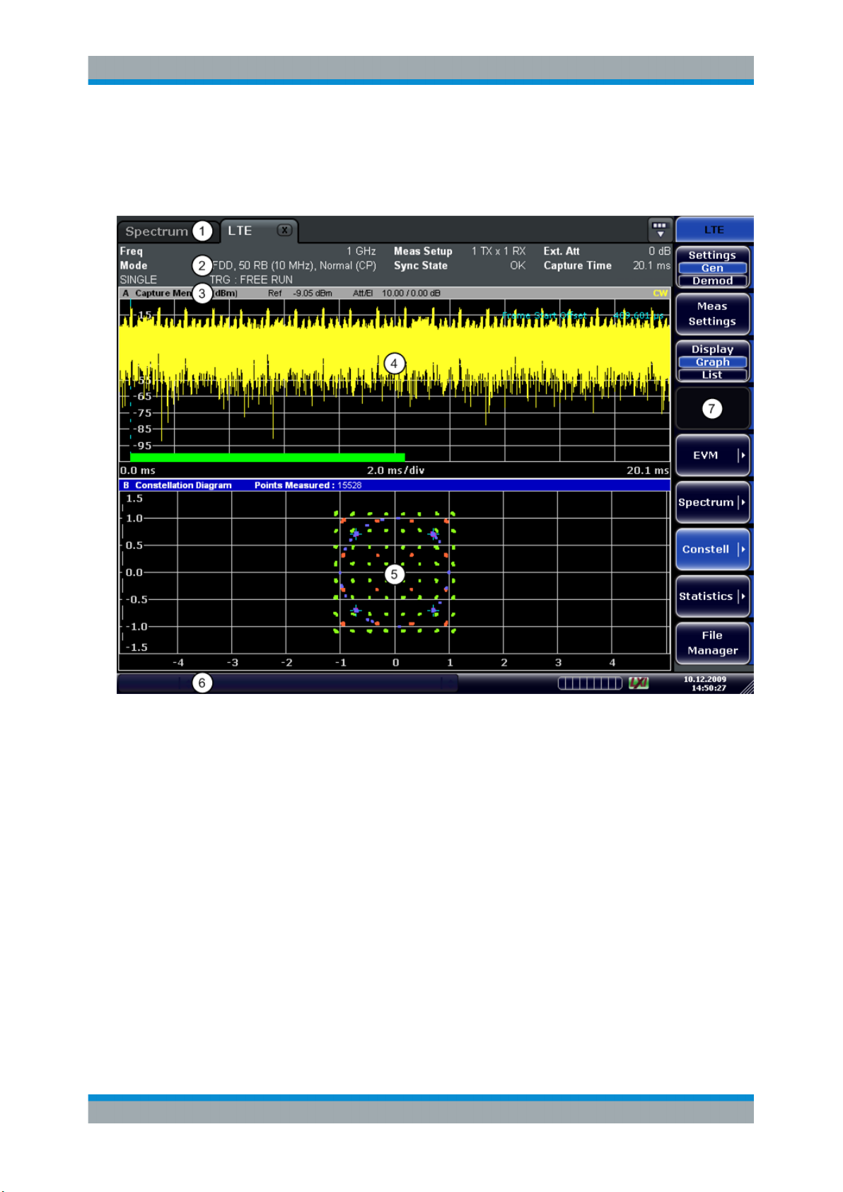
Elements and layout of the user interface
The user interface of the LTE measurement application is made up of several elements.
Welcome
Application Overview
1 = Channel Bar: contains all currently active measurement applications
2 = Table Header: shows basic measurement information, e.g. the frequency
3 = Result Display Header: shows information about the trace
4 = Result Display Screen A: shows the measurement results
5 = Result Display Screen B: shows the measurement results
6 = Status Bar: shows the measurement progress, software messages and errors
7 = Softkeys: open settings dialogs and select result displays
The status bar
The status bar is located at the bottom of the display. It shows the current measurement status and its progress in a running measurement. The status bar also shows
warning and error messages. Error messages are generally highlighted.
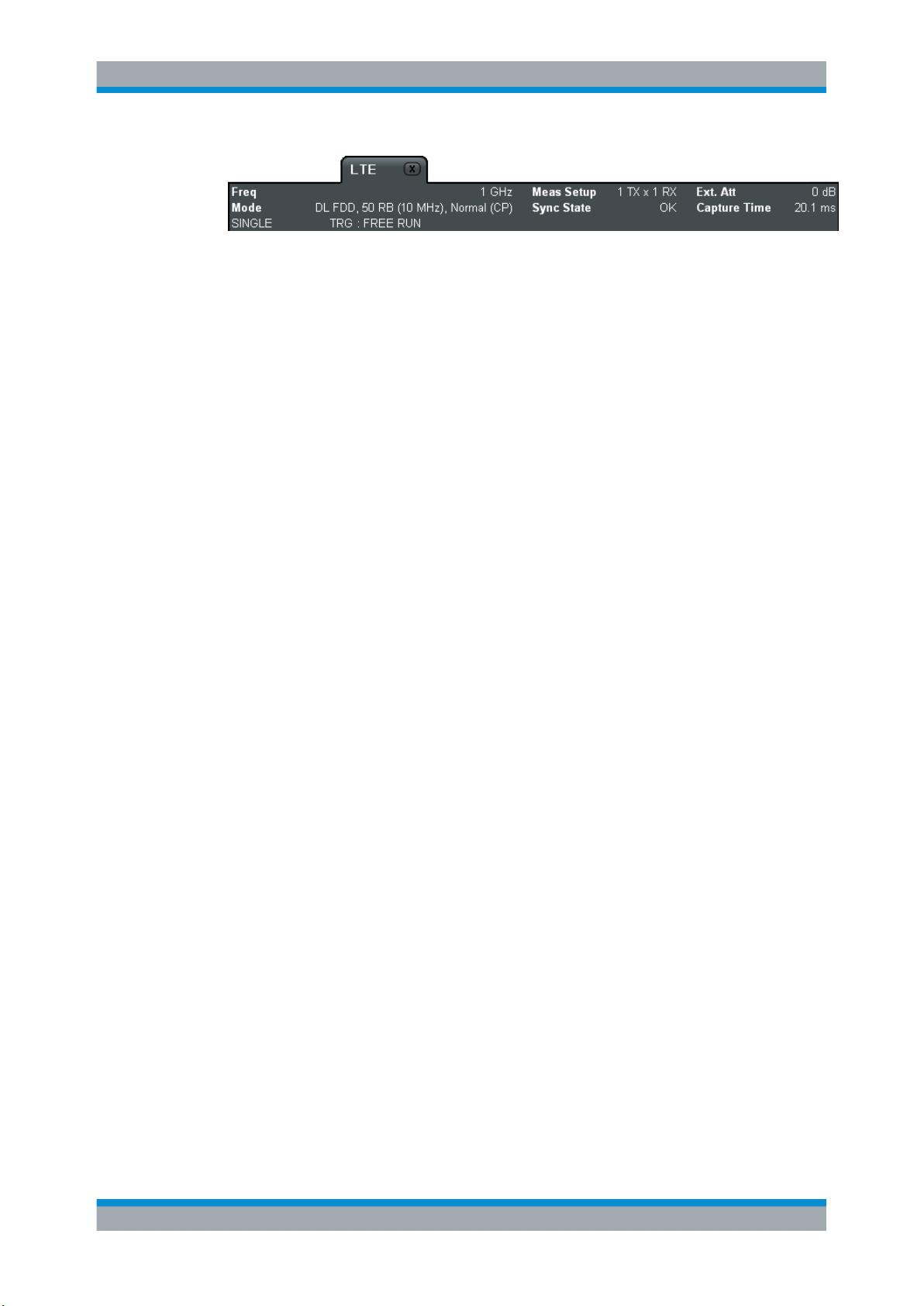
Display of measurement settings
The header table above the result displays shows information on hardware and measurement settings.
22User Manual 1176.7678.02 ─ 06
R&S®FSV-K10x (LTE Uplink)
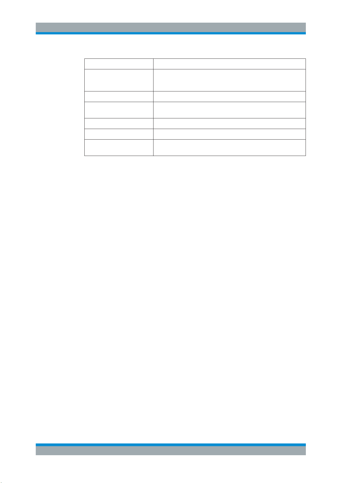
Table 3-1: Information displayed in the channel bar in the LTE measurement application
Freq The analyzer RF frequency.
Mode Link direction, duplexing, cyclic prefix and maximum number of physical
Meas Setup Number of transmitting and receiving antennas.
Welcome
Support
resource blocks (PRBs) / signal bandwidth.
Sync State The following synchronization states can occur:
Ext. Att External attenuation in dB.
Capture Time Capture length in ms.
3.3 Support
If you encounter any problems when using the application, you can contact the
Rohde & Schwarz support to get help for the problem.
To make the solution easier, use the "R&S Support" softkey to export useful information for troubleshooting. The R&S FSVA/FSV stores the information in a number of files
that are located in the R&S FSVA/FSV directory
C:\R_S\Instr\user\LTE\Support. If you contact Rohde & Schwarz to get help on
a certain problem, send these files to the support in order to identify and solve the
problem faster.
●
OK The synchronization was successful.
●
FAIL The synchronization has failed.
Remote command:
[SENSe:]SYNC[:CC<cc>][:STATe]? on page 100
23User Manual 1176.7678.02 ─ 06
R&S®FSV-K10x (LTE Uplink)
4 Measurement Basics
● Symbols and Variables............................................................................................24
● Overview................................................................................................................. 25
● The LTE Uplink Analysis Measurement Application................................................25
● SRS EVM Calculation............................................................................................. 29
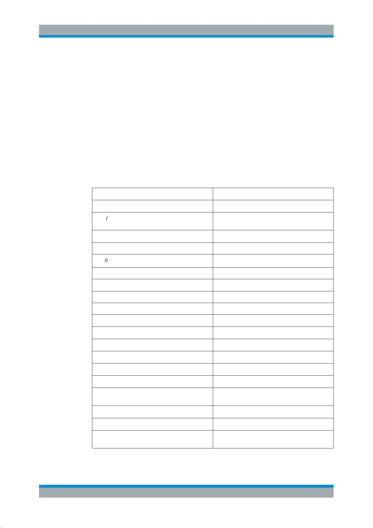
4.1 Symbols and Variables
The following chapters use various symbols and variables in the equations that the
measurements are based on. The table below explains these symbols for a better
understanding of the measurement principles.
Measurement Basics
Symbols and Variables
a
l,kâl,k
A
l,k
Δf, Δ
coarse
Δf
res
ζ
H
l,k, l,k
i time index
î
, î
coarse
fine
k subcarrier index
l SC-FDMA symbol index
N
DS
N
FFT
N
g
N
s
N
TX
data symbol (actual, decided)
data symbol after DFT-precoding
carrier frequency offset between transmitter and
receiver (actual, coarse estimate)
residual carrier frequency offset
relative sampling frequency offset
channel transfer function (actual, estimate)
timing estimate (coarse, fine)
number of SC-FDMA data symbols
length of FFT
number of samples in cyclic prefix (guard interval)
number of Nyquist samples
number of allocated subcarriers
N
k,l
n index of modulated QAM symbol before DFT pre-
Φ
l
r
i
R'
k,l
noise sample
coding
common phase error
received sample in the time domain
uncompensated received sample in the frequency
domain
24User Manual 1176.7678.02 ─ 06
R&S®FSV-K10x (LTE Uplink)
Measurement Basics
The LTE Uplink Analysis Measurement Application
r
n,l
T duration of the useful part of an SC-FDMA symbol
T
g
T
s
4.2 Overview
The digital signal processing (DSP) involves several stages until the software can present results like the EVM.
The contents of this chapter are structured like the DSP.
equalized received symbols of measurement path
after IDFT
duration of the guard interval
total duration of SC-FDMA symbol
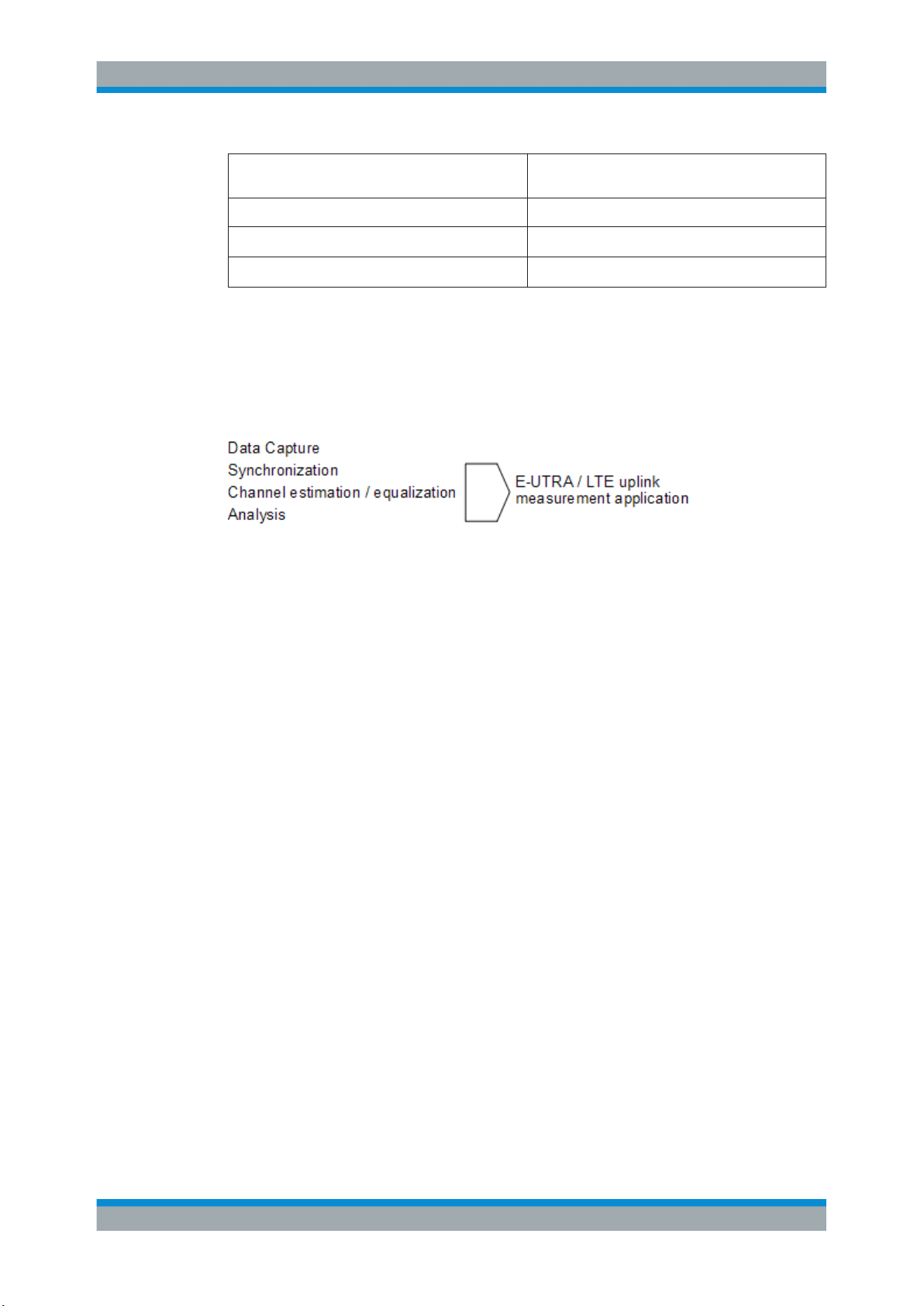
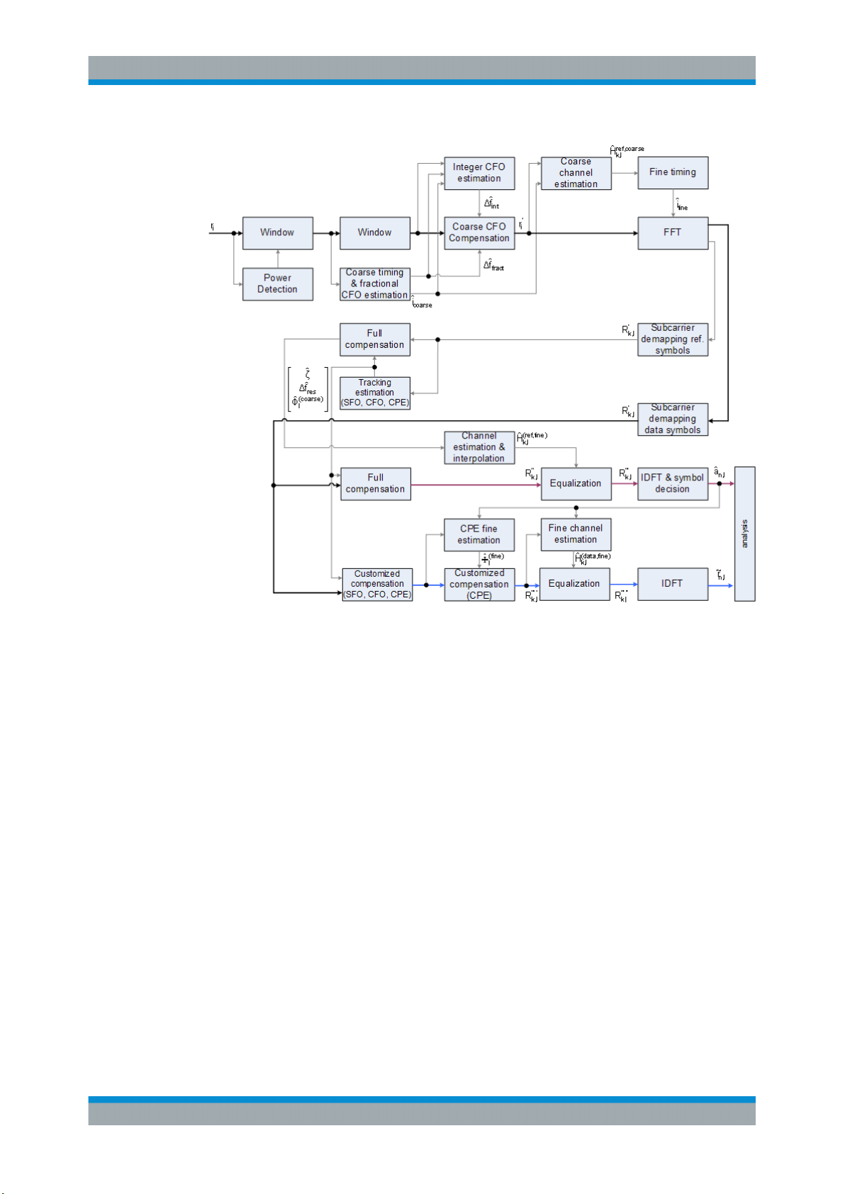
4.3 The LTE Uplink Analysis Measurement Application
The block diagram in Figure 4-1 shows the general structure of the LTE uplink measurement application from the capture buffer containing the I/Q data up to the actual
analysis block.
After synchronization a fully compensated signal is produced in the reference path
(purple) which is subsequently passed to the equalizer. An IDFT of the equalized symbols yields observations for the QAM transmit symbols a
mates â
are obtained via hard decision. Likewise a user defined compensation as
n,l
well as equalization is carried out in the measurement path (cyan) and after an IDFT
the observations of the QAM transmit symbols are provided. Accordingly, the measurement path might still contain impairments which are compensated in the reference
path. The symbols of both signal processing paths form the basis for the analysis.
from which the data esti-
n.l
25User Manual 1176.7678.02 ─ 06
R&S®FSV-K10x (LTE Uplink)
Measurement Basics
The LTE Uplink Analysis Measurement Application
Figure 4-1: Block diagram for the LTE UL measurement application
4.3.1 Synchronization
In a first step the areas of sufficient power are identified within the captured I/Q data
stream which consists of the receive samples ri. For each area of sufficient power, the
analyzer synchronizes on subframes of the uplink generic frame structure [3]. After this
coarse timing estimation, the fractional part as well as the integer part of the carrier frequency offset (CFO) are estimated and compensated. In order to obtain an OFDM
demodulation via FFT of length N
lished which refines the coarse timing estimate.
A phase tracking based on the reference SC-FDMA symbols is performed in the frequency domain. The corresponding tracking estimation block provides estimates for
●
the relative sampling frequency offset ζ
●
the residual carrier frequency offset Δf
●
the common phase error Φ
According to references [7] and [8], the uncompensated samples R'
ded domain can be stated as
that is not corrupted by ISI, a fine timing is estab-
FFT
res
l
in the DFT-preco-
k,l
26User Manual 1176.7678.02 ─ 06
R&S®FSV-K10x (LTE Uplink)
lk
lTfNNjlkNNjj
lklklk
NeeeHAR
CFOres
resFFTS
SFO
FFTS
CPE
l
,
22
,,
'
,
.
2
,
,,
,
ˆ
~
ln
lnln
kl
aE
ar
EVM
lnlnln
arEVM
,,,
ˆ
~
Equation 4-1:
with
●
the DFT precoded data symbol A
●
the channel transfer function H
●
the number of Nyquist samples NS within the total duration TS,
●
the duration of the useful part of the SC-FDMA symbol T=TS-T
●
the independent and Gaussian distributed noise sample N
Within one SC-FDMA symbol, both the CPE and the residual CFO cause the same
phase rotation for each subcarrier, while the rotation due to the SFO depends linearly
on the subcarrier index. A linear phase increase in symbol direction can be observed
for the residual CFO as well as for the SFO.
Measurement Basics
The LTE Uplink Analysis Measurement Application
on subcarrier k at SC-FDMA symbol l,
k,l
,
k,l
g
k,l
The results of the tracking estimation block are used to compensate the samples R'
completely in the reference path and according to the user settings in the measure-
ment path. Thus the signal impairments that are of interest to the user are left uncompensated in the measurement path.
After having decoded the data symbols in the reference path, an additional data-aided
phase tracking can be utilized to refine the common phase error estimation.
4.3.2 Analysis
The analysis block of the EUTRA/LTE uplink measurement application allows to compute a variety of measurement variables.
EVM
The most important variable is the error vector magnitude which is defined as
Equation 4-2:
for QAM symbol n before precoding and SC-FDMA symbol l. Since the normalized
average power of all possible constellations is 1, the equation can be simplified to
k,l
Equation 4-3:
The average EVM of all data subcarriers is then
27User Manual 1176.7678.02 ─ 06

R&S®FSV-K10x (LTE Uplink)
101
0
2
,
1
LB TX
NlN
n
ln
TXDS
data
EVM
NN
EVM
tsjQtsItr
|1|balancegain modulator Q
}1arg{mismatch quadrature Q
S
RB
Tt
Nc
c
RBS
RBabsolute
RBrelative
ftY
NT
Emissions
Emissions
112
2
,
1
Equation 4-4:
for NDS SC-FDMA data symbols and the NTX allocated subcarriers.
I/Q imbalance
The I/Q imbalance contained in the continuous received signal r(t) can be written as
Equation 4-5:
where s(t) is the transmit signal and I and Q are the weighting factors describing the
I/Q imbalance. We define that I:=1 and Q:=1+ΔQ.
The I/Q imbalance estimation makes it possible to evaluate the
Measurement Basics
The LTE Uplink Analysis Measurement Application
Equation 4-6:
and the
Equation 4-7:
based on the complex-valued estimate .
Basic in-band emissions measurement
The in-band emissions are a measure of the interference falling into the non-allocated
resources blocks.
The relative in-band emissions are given by
Equation 4-8:
where TS is a set |TS| of SC-FDMA symbols with the considered modulation scheme
being active within the measurement period, ΔRB is the starting frequency offset
between the allocated RB and the measured non-allocated RB (e.g. ΔRB=1 or ΔRB=-1
for the first adjacent RB), c is the lower edge of the allocated BW, and Y(t,f) is the fre-
quency domain signal evaluated for in-band emissions. NRB is the number of allocated
RBs .
The basic in-band emissions measurement interval is defined over one slot in the time
domain.
28User Manual 1176.7678.02 ─ 06
R&S®FSV-K10x (LTE Uplink)
Other measurement variables
Without going into detail, the EUTRA/LTE uplink measurement application additionally
provides the following results:
●
Total power
●
Constellation diagram
●
Group delay
●
I/Q offset
●
Crest factor
●
Spectral flatness
4.4 SRS EVM Calculation
In order to calculate an accurate EVM, a channel estimation needs to be done prior to
the EVM calculation. However, the channel estimation requires a minimum of two
resource elements containing reference symbols on a subcarrier. Depending on the
current Channel Estimation Range setting, this means that either at least two reference
symbols ("Pilot Only") or one reference symbol and at least one data symbol ("Pilot
and Payload") need to be available on the subcarrier the EVM is to be measured.
Measurement Basics
SRS EVM Calculation
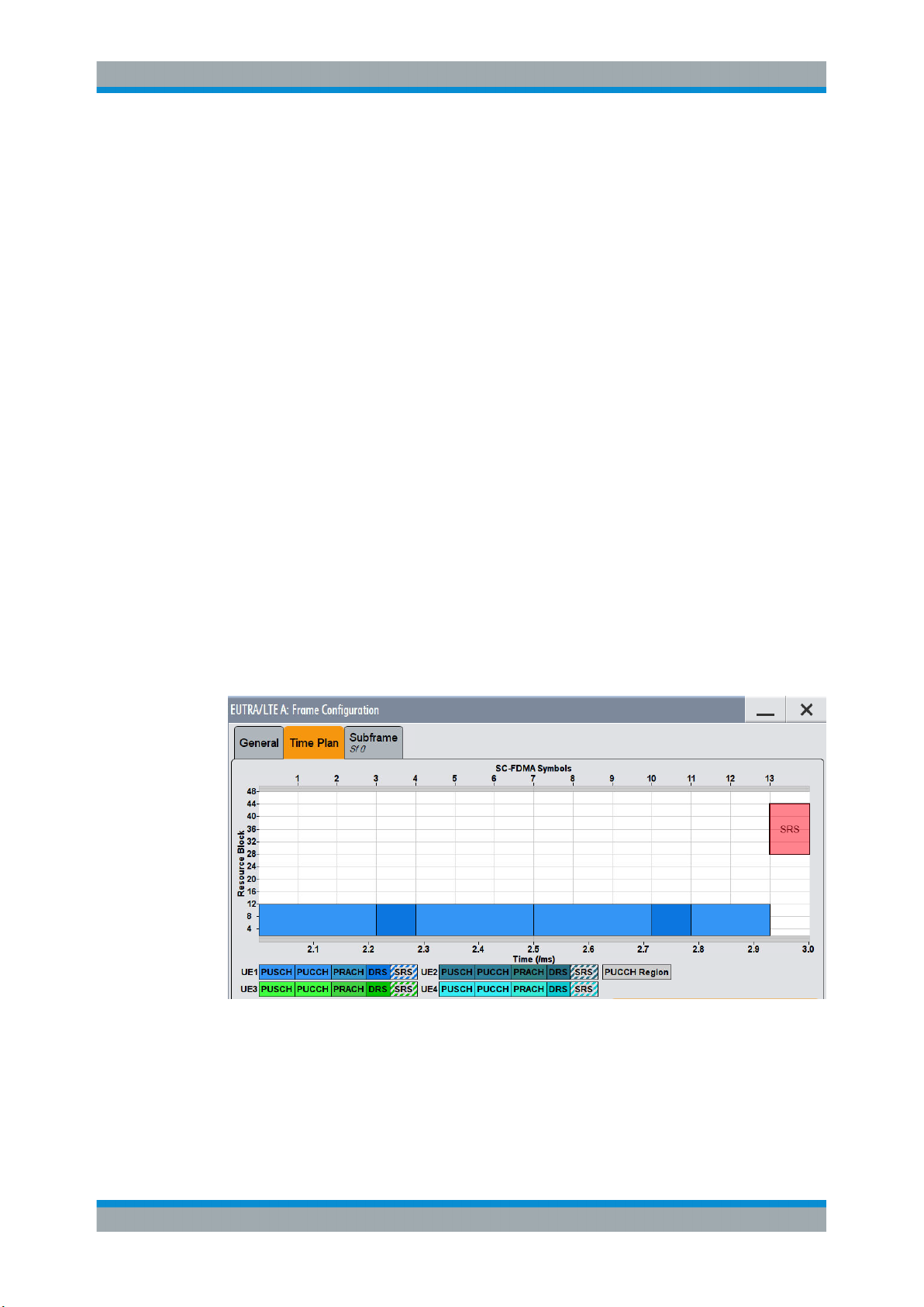
For PUSCH, PUCCH and PRACH regions, these conditions are normally fulfilled
because the DMRS (= Demodulation Reference Signal) is already included. However,
the SRS may also be located on subcarriers which do not occupy any other reference
symbols (see Figure 4-2).
Figure 4-2: No EVM can be measured for the SRS
In this case it is not reasonable to calculate an EVM and no SRS EVM value will be
displayed for the corresponding subframe.
29User Manual 1176.7678.02 ─ 06
R&S®FSV-K10x (LTE Uplink)
If the SRS subcarriers contain two DMRS symbols (or one DMRS and one PUSCH for
"Pilot and Payload" channel estimation range) the SRS EVM can be measured (see
Figure 4-3).
Measurement Basics
SRS EVM Calculation
Figure 4-3: The EVM of the complete SRS can be measured
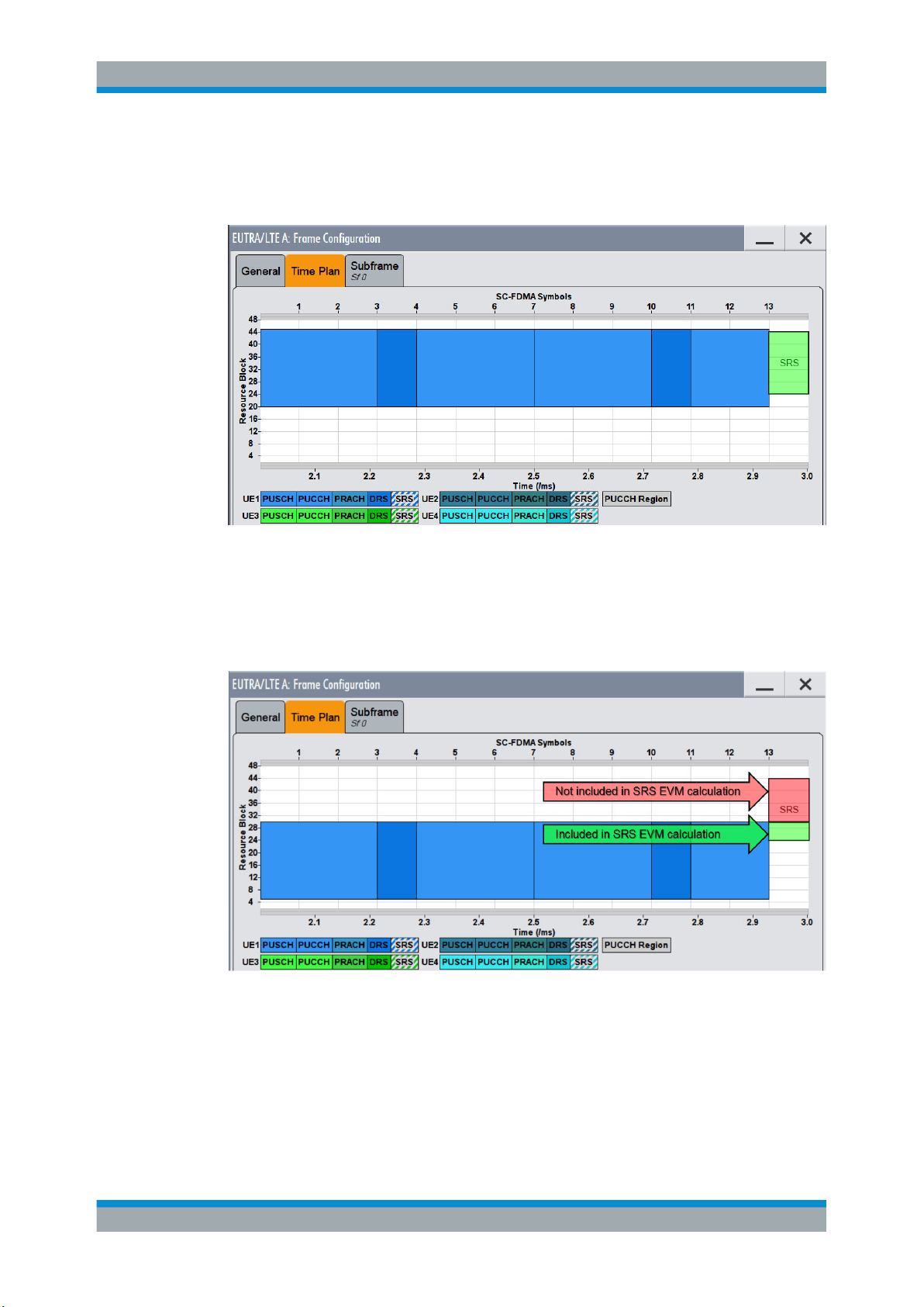
The SRS allocation might cover subcarriers which partly fulfill the conditions mentioned
above and partly do not. In this case the EVM value given in the Allocation Summary
will be calculated based only on the subcarriers which fulfill the above requirements
(see Figure 4-4).
Figure 4-4: The EVM for parts of the SRS can be measured
30User Manual 1176.7678.02 ─ 06
 Loading...