


R&S®FSPN
Spectrum Monitor
User Manual
(;Ý]X2)
1179454002
Version 02

This document describes the following R&S®FSPN models:
●
R&S®FSPN8 (1322.8003K06)
●
R&S®FSPN26 (1322.8003K24)
The Spectrum Monitor is integral part of the R&S FSPN and is always available.
© 2021 Rohde & Schwarz GmbH & Co. KG
Mühldorfstr. 15, 81671 München, Germany
Phone: +49 89 41 29 - 0
Email: info@rohde-schwarz.com
Internet: www.rohde-schwarz.com
Subject to change – data without tolerance limits is not binding.
R&S® is a registered trademark of Rohde & Schwarz GmbH & Co. KG.
Trade names are trademarks of the owners.
1179.4540.02 | Version 02 | R&S®FSPN
Throughout this manual, products from Rohde & Schwarz are indicated without the ® symbol , e.g. R&S®FSWP is indicated as
R&S FSWP.

R&S®FSPN
Contents
Contents
1 Preface.................................................................................................... 5
1.1 About this Manual......................................................................................................... 5
1.2 Documentation Overview............................................................................................. 5
1.3 Conventions Used in the Documentation...................................................................7
2 Welcome to the Spectrum Monitor Application.................................. 8
2.1 Starting the Spectrum Monitor Application................................................................8
3 Measurement and Result Displays.....................................................10
4 Configuration........................................................................................12
4.1 Configuration Overview..............................................................................................12
4.2 Import/Export Functions............................................................................................ 13
4.3 Configuring Data Inputs and Outputs....................................................................... 15
4.4 Configuring the Amplitude.........................................................................................33
4.5 Configuring Frequency Characteristics....................................................................38
4.6 Configuring Triggered Measurements...................................................................... 39
4.7 Data Acquisition and Bandwidth Settings................................................................43
4.8 Display Configuration.................................................................................................49
4.9 Transducer...................................................................................................................49
5 Analysis................................................................................................ 60
5.1 Configuring Standard Traces.....................................................................................60
5.2 Configuring Spectrograms.........................................................................................63
5.3 Marker Settings........................................................................................................... 67
5.4 Limit Lines................................................................................................................... 82
6 Remote Commands for the Spectrum Monitor................................. 92
6.1 Introduction................................................................................................................. 92
6.2 Common Suffixes........................................................................................................97
6.3 Activating Spectrum Monitor Measurements...........................................................97
6.4 Performing Measurements.......................................................................................101
6.5 Retrieving Results.....................................................................................................108
6.6 Configuring Spectrum Monitor Measurements...................................................... 116
6.7 Analyzing Results..................................................................................................... 173
3User Manual 1179.4540.02 ─ 02

R&S®FSPN
Contents
6.8 Importing and Exporting I/Q Data............................................................................229
Annex.................................................................................................. 231
A I/Q Data File Format (iq-tar)...............................................................231
A.1 I/Q Parameter XML File Specification......................................................................232
A.2 I/Q Data Binary File................................................................................................... 236
B Reference: Format Description for I/Q Data Files........................... 239
C Formats for Returned Values: ASCII Format and Binary Format.. 241
List of Remote Commands (Spectrum Monitor)............................. 242
Index....................................................................................................249
4User Manual 1179.4540.02 ─ 02

R&S®FSPN
Preface
Documentation Overview
1 Preface
1.1 About this Manual
This R&S FSPN Spectrum Monitor User Manual provides all the information specific to
the application and processing I/Q data. All general instrument functions and settings
common to all applications are described in the main R&S FSPN User Manual.
The main focus in this manual is on the measurement results and the tasks required to
obtain them.
1.2 Documentation Overview
This section provides an overview of the R&S FSPN user documentation. Unless
specified otherwise, you find the documents on the R&S FSPN product page at:
www.rohde-schwarz.com/manual/FSPN
1.2.1 Getting Started Manual
Introduces the R&S FSPN and describes how to set up and start working with the
product. Includes basic operations, typical measurement examples, and general information, e.g. safety instructions, etc.
A printed version is delivered with the instrument. A PDF version is available for download on the Internet.
1.2.2 User Manuals and Help
The user manual contains the description of all instrument modes and functions. It also
provides an introduction to remote control, a complete description of the remote control
commands with programming examples, and information on maintenance, instrument
interfaces and error messages. Includes the contents of the getting started manual.
The contents of the user manual are available as help in the R&S FSPN. The help
offers quick, context-sensitive access to the complete information for the instrument
and its firmware.
The user manual is also available for download or for immediate display on the Internet.
5User Manual 1179.4540.02 ─ 02

R&S®FSPN
1.2.3 Service Manual
1.2.4 Instrument Security Procedures
1.2.5 Printed Safety Instructions
Preface
Documentation Overview
Describes the performance test for checking the rated specifications, module replacement and repair, firmware update, troubleshooting and fault elimination, and contains
mechanical drawings and spare part lists.
The service manual is available for registered users on the global Rohde & Schwarz
information system (GLORIS):
https://gloris.rohde-schwarz.com
Deals with security issues when working with the R&S FSPN in secure areas. It is
available for download on the Internet.
Provides safety information in many languages. The printed document is delivered with
the product.
1.2.6 Data Sheets and Brochures
The data sheet contains the technical specifications of the R&S FSPN. It also lists the
firmware applications and their order numbers, and optional accessories.
The brochure provides an overview of the instrument and deals with the specific characteristics.
See www.rohde-schwarz.com/brochure-datasheet/FSPN
1.2.7 Release Notes and Open Source Acknowledgment (OSA)
The release notes list new features, improvements and known issues of the current
firmware version, and describe the firmware installation.
The open-source acknowledgment document provides verbatim license texts of the
used open source software.
See www.rohde-schwarz.com/firmware/FSPN
1.2.8 Application Notes, Application Cards, White Papers, etc.
These documents deal with special applications or background information on particular topics.
See www.rohde-schwarz.com/application/FSPN
6User Manual 1179.4540.02 ─ 02

R&S®FSPN
1.3.1 Typographical Conventions
Preface
Conventions Used in the Documentation
1.3 Conventions Used in the Documentation
The following text markers are used throughout this documentation:
Convention Description
"Graphical user interface elements"
[Keys] Key and knob names are enclosed by square brackets.
Filenames, commands,
program code
Input Input to be entered by the user is displayed in italics.
Links Links that you can click are displayed in blue font.
"References" References to other parts of the documentation are enclosed by quota-
All names of graphical user interface elements on the screen, such as
dialog boxes, menus, options, buttons, and softkeys are enclosed by
quotation marks.
Filenames, commands, coding samples and screen output are distinguished by their font.
tion marks.
1.3.2 Conventions for Procedure Descriptions
When operating the instrument, several alternative methods may be available to perform the same task. In this case, the procedure using the touchscreen is described.
Any elements that can be activated by touching can also be clicked using an additionally connected mouse. The alternative procedure using the keys on the instrument or
the on-screen keyboard is only described if it deviates from the standard operating procedures.
The term "select" may refer to any of the described methods, i.e. using a finger on the
touchscreen, a mouse pointer in the display, or a key on the instrument or on a keyboard.
1.3.3 Notes on Screenshots
When describing the functions of the product, we use sample screenshots. These
screenshots are meant to illustrate as many as possible of the provided functions and
possible interdependencies between parameters. The shown values may not represent
realistic usage scenarios.
The screenshots usually show a fully equipped product, that is: with all options installed. Thus, some functions shown in the screenshots may not be available in your particular product configuration.
7User Manual 1179.4540.02 ─ 02

R&S®FSPN
Welcome to the Spectrum Monitor Application
Starting the Spectrum Monitor Application
2 Welcome to the Spectrum Monitor Applica-
tion
The R&S FSPN Spectrum Monitor is a firmware application that adds functionality to
view the captured frequency spectrum on the R&S FSPN.
It runs on the phase noise analyzer hardware and is included with the R&S FSPN.
It has the following characteristics and limitations:
●
When you open a spectrum monitor, the frequency, level and input parameters are
initially adopted from the phase noise application (you can change them in the
spectrum monitor, of course).
●
Maximum analysis bandwidth of 20 MHz and sample rate of 25 MHz (and no support of bandwidth extensions).
●
Advanced data acquisition settings are unavailable.
●
I/Q data import and export
●
Spectrograms, general marker functionality, marker functions and limit lines
●
Only external triggers are supported.
●
Only evaluation of the frequency spectrum is supported.
●
Trace mathematics are not available.
This user manual contains a description of the functionality that the application provides, including remote control operation.
The functionality of the spectrum monitor application is limited in comparison to a full
I/Q analyzer. Therefore some functions and result displays described in this user manual are not available with this version of the spectrum monitor application.
All functions not discussed in this manual are the same as in the base unit and are
described in the R&S FSPN User Manual. The latest version is available for download
at the product homepage http://www.rohde-schwarz.com/product/FSPN.
2.1 Starting the Spectrum Monitor Application
The Spectrum Monitor is an application on the R&S FSPN.
To activate the Spectrum Monitor application
1. Select the [MODE] key.
A dialog box opens that contains all applications currently available on your
R&S FSPN.
2. Select the "Spectrum Monitor" item.
8User Manual 1179.4540.02 ─ 02

R&S®FSPN
Welcome to the Spectrum Monitor Application
Starting the Spectrum Monitor Application
The R&S FSPN opens a new channel for the Spectrum Monitor application.
9User Manual 1179.4540.02 ─ 02
R&S®FSPN
Measurement and Result Displays
3 Measurement and Result Displays
Access: "Overview" > "Display Config"
Or: [MEAS] > "Display Config"
In the Spectrum Monitor application, data that was captured by or imported to the
R&S FSPN can be evaluated in various different result displays.
Result displays:
Spectrum ......................................................................................................................10
Marker Table ................................................................................................................ 10
Marker Peak List ...........................................................................................................11
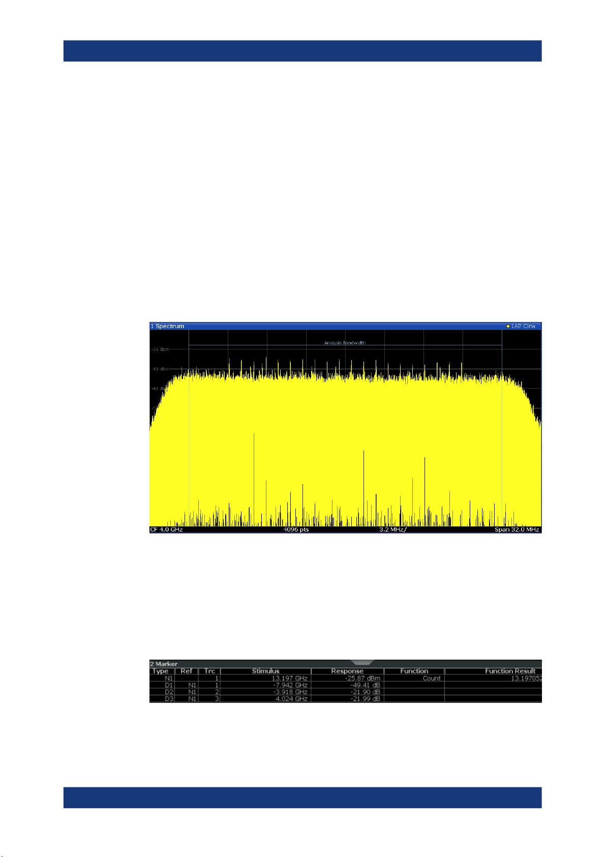
Spectrum
Displays the frequency spectrum of the captured I/Q samples.
Remote command:
LAY:ADD:WIND? '1',RIGH,FREQ, see LAYout:ADD[:WINDow]? on page 163
Results:
TRACe<n>[:DATA] on page 112
Marker Table
Displays a table with the current marker values for the active markers.
This table is displayed automatically if configured accordingly.
Remote command:
LAY:ADD? '1',RIGH, MTAB, see LAYout:ADD[:WINDow]? on page 163
Results:
10User Manual 1179.4540.02 ─ 02

R&S®FSPN
Measurement and Result Displays
CALCulate<n>:MARKer<m>:X on page 115
CALCulate<n>:MARKer<m>:Y? on page 116
Marker Peak List
The marker peak list determines the frequencies and levels of peaks in the spectrum or
time domain. How many peaks are displayed can be defined, as well as the sort order.
In addition, the detected peaks can be indicated in the diagram. The peak list can also
be exported to a file for analysis in an external application.
Remote command:
LAY:ADD? '1',RIGH, PEAK, see LAYout:ADD[:WINDow]? on page 163
Results:
CALCulate<n>:MARKer<m>:X on page 115
CALCulate<n>:MARKer<m>:Y? on page 116
11User Manual 1179.4540.02 ─ 02
R&S®FSPN
Configuration
Configuration Overview
4 Configuration
The Spectrum Monitor is a special application on the R&S FSPN, which you activate
using the [MODE] key on the front panel.
● Configuration Overview...........................................................................................12
● Import/Export Functions..........................................................................................13
● Configuring Data Inputs and Outputs......................................................................15
● Configuring the Amplitude.......................................................................................33
● Configuring Frequency Characteristics...................................................................38
● Configuring Triggered Measurements.....................................................................39
● Data Acquisition and Bandwidth Settings............................................................... 43
● Display Configuration..............................................................................................49
● Transducer..............................................................................................................49
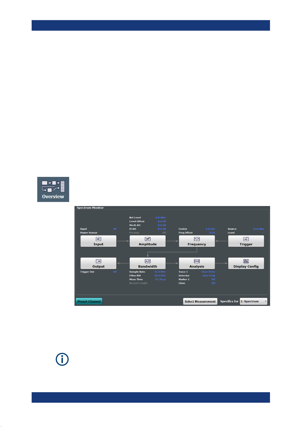
4.1 Configuration Overview
Throughout the measurement channel configuration, an overview of the most important
currently defined settings is provided in the "Overview". The "Overview" is displayed
when you select the "Overview" icon, which is available at the bottom of all softkey
menus.
In addition to the main measurement settings, the "Overview" provides quick access to
the main settings dialog boxes. The individual configuration steps are displayed in the
order of the data flow. Thus, you can easily configure an entire measurement channel
from input over processing to output and analysis by stepping through the dialog boxes
as indicated in the "Overview".
The Overview varies depending on the application; for detailed descriptions see the
corresponding application User Manual.
12User Manual 1179.4540.02 ─ 02

R&S®FSPN
Configuration
Import/Export Functions
To configure settings
► Select any button in the "Overview" to open the corresponding dialog box.
Select a setting in the channel bar (at the top of the measurement channel tab) to
change a specific setting.
Preset Channel............................................................................................................. 13
Specific Settings for ..................................................................................................... 13
Preset Channel
Select the "Preset Channel" button in the lower left-hand corner of the "Overview" to
restore all measurement settings in the current channel to their default values.
Remote command:
SYSTem:PRESet:CHANnel[:EXEC] on page 100
Specific Settings for
The channel may contain several windows for different results. Thus, the settings indicated in the "Overview" and configured in the dialog boxes vary depending on the
selected window.
Select an active window from the "Specific Settings for" selection list that is displayed
in the "Overview" and in all window-specific configuration dialog boxes.
The "Overview" and dialog boxes are updated to indicate the settings for the selected
window.
4.2 Import/Export Functions
Access: "Save" / "Open" icon in the toolbar > "Import" / "Export"
The R&S FSPN provides various evaluation methods for the results of the performed
measurements. However, you may want to evaluate the data with further, external
applications. In this case, you can export the measurement data to a standard format
file (ASCII or XML). Some of the data stored in these formats can also be re-imported
to the R&S FSPN for further evaluation later, for example in other applications.
The following data types can be exported (depending on the application):
●
Trace data
●
Table results, such as result summaries, marker peak lists etc.
●
I/Q data (in applications that process I/Q data)
The following data types can be imported (depending on the application):
●
I/Q data (in applications that process I/Q data)
I/Q data can only be imported and exported in applications that process I/Q data, such
as the I/Q analyzer or other optional applications.
See the corresponding user manuals for those applications for details.
13User Manual 1179.4540.02 ─ 02

R&S®FSPN
Configuration
Import/Export Functions
These functions are only available if no measurement is running.
In particular, if Continuous Sweep / Run Cont is active, the import/export functions are
not available.
Import ...........................................................................................................................14
└ I/Q Import .......................................................................................................14
└ File Explorer..........................................................................................14
Export ...........................................................................................................................14
└ Trace Export Configuration ............................................................................14
└ I/Q Export .......................................................................................................14
└ File Explorer..........................................................................................15
Import
Access: "Save/Recall" > Import
Provides functions to import data.
I/Q Import ← Import
Opens a file selection dialog box to select an import file that contains I/Q data. This
function is only available in single sweep mode and only in applications that process
I/Q data, such as the I/Q Analyzer or optional applications.
Input from I/Q data files is imported as it was stored, including any correction factors,
for example from transducers or SnP files. Any currently configured correction factors
at the time of import, however, are not applied.
Remote command:
MMEMory:LOAD:IQ:STATe on page 229
File Explorer ← I/Q Import ← Import
Opens the Microsoft Windows File Explorer.
Remote command:
not supported
Export
Access: "Save/Recall" > Export
Opens a submenu to configure data export.
Trace Export Configuration ← Export
Opens the "Traces" dialog box to configure the trace and data export settings.
I/Q Export ← Export
Opens a file selection dialog box to define an export file name to which the I/Q data is
stored. This function is only available in single sweep mode.
It is not available in the Spectrum application, only in applications that process I/Q
data, such as the I/Q Analyzer or optional applications.
For details, see the description in the R&S FSPN I/Q Analyzer User Manual ("Importing
and Exporting I/Q Data").
14User Manual 1179.4540.02 ─ 02

R&S®FSPN
Configuration
Configuring Data Inputs and Outputs
Note: Storing large amounts of I/Q data (several Gigabytes) can exceed the available
(internal) storage space on the R&S FSPN. In this case, it can be necessary to use an
external storage medium.
Remote command:
MMEMory:STORe<n>:IQ:STATe on page 230
MMEMory:STORe<n>:IQ:COMMent on page 229
File Explorer ← I/Q Export ← Export
Opens the Microsoft Windows File Explorer.
Remote command:
not supported
4.3 Configuring Data Inputs and Outputs
The R&S FSPN can analyze signals from different input sources and provide various
types of output (such as video or trigger signals).
● Inputs...................................................................................................................... 15
● Outputs....................................................................................................................31
4.3.1 Inputs
The Spectrum Monitor supports several input sources.
● RF Input.................................................................................................................. 15
● Settings for Input from I/Q Data Files......................................................................17
● Power Sensors........................................................................................................18
● Probes Input............................................................................................................25
4.3.1.1 RF Input
Access: "Overview" > "Input/Frontend" > "Input Source" > "Radio Frequency"
Radio Frequency State ................................................................................................ 15
Input Coupling ..............................................................................................................16
Impedance ................................................................................................................... 16
High Pass Filter 1 to 3 GHz ..........................................................................................16
YIG-Preselector ............................................................................................................16
Radio Frequency State
Activates input from the "RF Input" connector.
Remote command:
INPut<ip>:SELect on page 120
15User Manual 1179.4540.02 ─ 02

R&S®FSPN
Configuration
Configuring Data Inputs and Outputs
Input Coupling
AC coupling blocks any DC voltage from the input signal. This is the default setting to
prevent damage to the instrument. Very low frequencies in the input signal may be distorted.
However, some specifications require DC coupling. In this case, you must protect the
instrument from damaging DC input voltages manually. For details, refer to the data
sheet.
Remote command:
INPut<ip>:COUPling on page 117
Impedance
The R&S FSPN has an internal impedance of 50 Ω. However, some applications use
other impedance values. In order to match the impedance of an external application to
the impedance of the R&S FSPN, an impedance matching pad can be inserted at the
input. If the type and impedance value of the used matching pad is known to the
R&S FSPN, it can convert the measured units accordingly so that the results are calculated correctly.
"50Ω"
(Default:) no conversion takes place
"75Ω"
"User"
Remote command:
INPut<ip>:IMPedance on page 119
INPut<ip>:IMPedance:PTYPe on page 119
High Pass Filter 1 to 3 GHz
Activates an additional internal high-pass filter for RF input signals from 1 GHz to
3 GHz. This filter is used to remove the harmonics of the analyzer to measure the harmonics for a DUT, for example.
(Note: for RF input signals outside the specified range, the high-pass filter has no
effect. For signals with a frequency of approximately 4 GHz upwards, the harmonics
are suppressed sufficiently by the YIG-preselector, if available.)
YIG-Preselector
Enables or disables the YIG-preselector, if available on the R&S FSPN.
An internal YIG-preselector at the input of the R&S FSPN ensures that image frequen-
cies are rejected. However, this is only possible for a restricted bandwidth. To use the
maximum bandwidth for signal analysis you can disable the YIG-preselector at the
input of the R&S FSPN, which can lead to image-frequency display.
The 50 Ω input impedance is transformed to a higher impedance
using a 75 Ω adapter of the selected "Pad Type": "Series-R" (default)
or "MLP" (Minimum Loss Pad)
The 50 Ω input impedance is transformed to a user-defined impedance value according to the selected "Pad Type": "Series-R"
(default) or "MLP" (Minimum Loss Pad)
Remote command:
INPut<ip>:FILTer:YIG[:STATe] on page 119
16User Manual 1179.4540.02 ─ 02
R&S®FSPN
4.3.1.2 Settings for Input from I/Q Data Files
Configuration
Configuring Data Inputs and Outputs
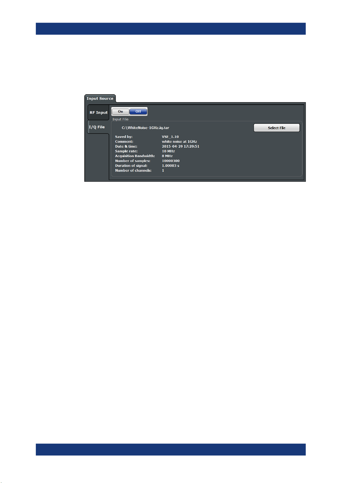
Access: "Overview" > "Input/Frontend" > "Input Source" > "I/Q File"
Or: [INPUT/OUTPUT] > "Input Source Config" > "Input Source" > "I/Q File"
I/Q Input File State........................................................................................................ 17
Select I/Q data file ........................................................................................................17
File Repetitions............................................................................................................. 17
I/Q Input File State
Enables input from the selected I/Q input file.
If enabled, the application performs measurements on the data from this file. Thus,
most measurement settings related to data acquisition (attenuation, center frequency,
measurement bandwidth, sample rate) cannot be changed. The measurement time
can only be decreased, to perform measurements on an extract of the available data
only.
Note: Even when the file input is disabled, the input file remains selected and can be
enabled again quickly by changing the state.
Remote command:
INPut<ip>:SELect on page 120
Select I/Q data file
Opens a file selection dialog box to select an input file that contains I/Q data.
The I/Q data must have a specific format (.iq.tar) as described in Chapter A, "I/Q
Data File Format (iq-tar)", on page 231.
The default storage location for I/Q data files is C:\R_S\INSTR\USER.
Remote command:
INPut<ip>:FILE:PATH on page 118
File Repetitions
Determines how often the data stream is repeatedly copied in the I/Q data memory to
create a longer record. If the available memory is not sufficient for the specified number of repetitions, the largest possible number of complete data streams is used.
17User Manual 1179.4540.02 ─ 02
R&S®FSPN
4.3.1.3 Power Sensors
Configuration
Configuring Data Inputs and Outputs
Remote command:
TRACe:IQ:FILE:REPetition:COUNt on page 121
The R&S FSPN can also analyze data from a connected power sensor.
● Basics on Power Sensors....................................................................................... 18
● Power Sensor Settings............................................................................................19
● How to Work With a Power Sensor.........................................................................23
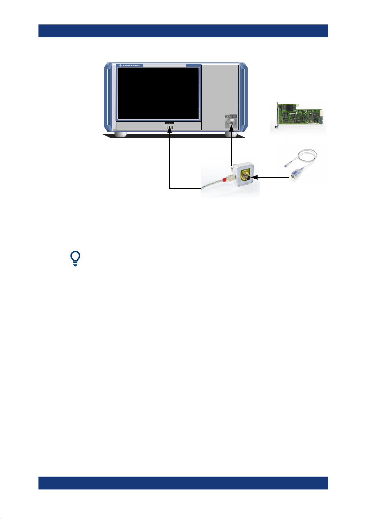
Basics on Power Sensors
For precise power measurement, up to 4 power sensors can be connected to the
instrument via the power sensor interface (on the front panel) or the USB connectors.
Both manual operation and remote control are supported.
For a detailed list of supported sensors, see the data sheet.
Power sensors can also be used to trigger a measurement at a specified power level,
e.g. from a signal generator (see "Using a Power Sensor as an External Power Trig-
ger" on page 18).
Signal
Source
Figure 4-1: Power sensor support – standard test setup
Power
Sensor
R&S NRP-Z3 /-Z4 /-
Z5 adaptor
R&S
FSWP
Using the power sensor with several applications
The power sensor cannot be used from the R&S FSPN firmware and the R&S Power
Viewer Plus (virtual power meter for displaying results of the R&S NRP power sensors)
simultaneously.
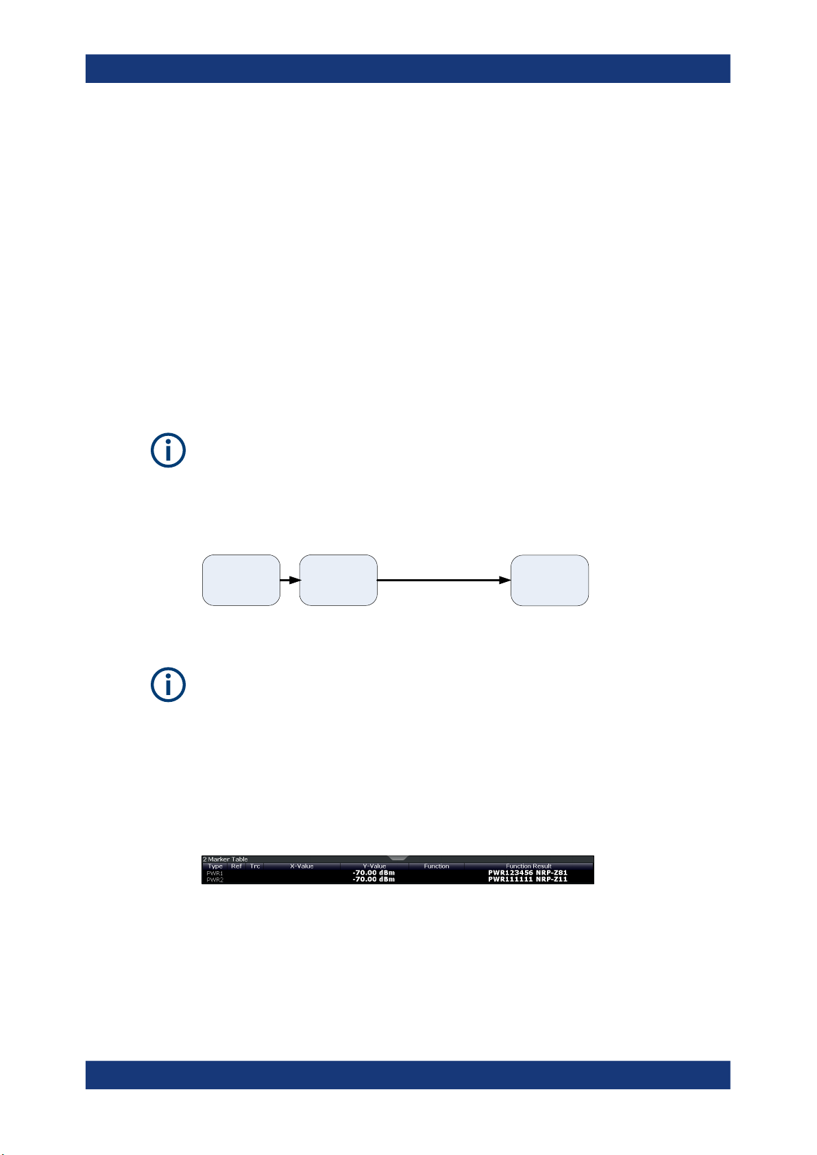
Result display
The results of the power sensor measurements are displayed in the marker table. For
each power sensor, a row is inserted. The sensor index is indicated in the "Type" column.
Using a Power Sensor as an External Power Trigger
Power sensors can be used to trigger a measurement at a specified power level, e.g.
from a signal generator. For a list of supported power sensors see the data sheet.
18User Manual 1179.4540.02 ─ 02
R&S®FSPN
Configuration
Configuring Data Inputs and Outputs
The R&S FSPN receives an external trigger signal when the defined trigger level is
measured by the power sensor. Power measurement results are provided as usual.
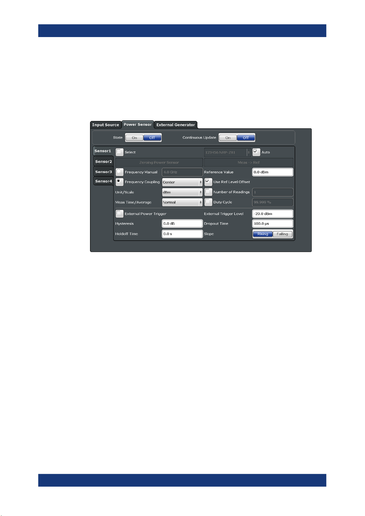
Power Sensor Settings
Access: "Overview" > "Input" > "Power Sensor" tab
Each sensor is configured on a separate tab.
State .............................................................................................................................20
Continuous Value Update ............................................................................................ 20
Select ........................................................................................................................... 20
Zeroing Power Sensor ................................................................................................. 20
Frequency Manual ....................................................................................................... 21
Frequency Coupling .....................................................................................................21
Unit/Scale .....................................................................................................................21
Meas Time/Average .....................................................................................................21
Setting the Reference Level from the Measurement Meas -> Ref ...............................21
Reference Value ...........................................................................................................21
Use Ref Level Offset ....................................................................................................22
Sensor Level Offset.......................................................................................................22
Average Count ( Number of Readings )........................................................................22
Duty Cycle ....................................................................................................................22
Using the power sensor as an external trigger .............................................................22
└ External Trigger Level ....................................................................................22
└ Hysteresis ...................................................................................................... 23
└ Trigger Holdoff ............................................................................................... 23
└ Drop-Out Time ............................................................................................... 23
└ Slope ..............................................................................................................23
19User Manual 1179.4540.02 ─ 02

R&S®FSPN
Configuration
Configuring Data Inputs and Outputs
State
Switches the power measurement for all power sensors on or off. Note that in addition
to this general setting, each power sensor can be activated or deactivated individually
by the Select setting on each tab. However, the general setting overrides the individual
settings.
Remote command:
[SENSe:]PMETer<p>[:STATe] on page 123
Continuous Value Update
If activated, the power sensor data is updated continuously during a sweep with a long
sweep time, and even after a single sweep has completed.
This function cannot be activated for individual sensors.
If the power sensor is being used as a trigger (see " Using the power sensor as an
external trigger " on page 22), continuous update is not possible; this setting is
ignored.
Remote command:
[SENSe:]PMETer<p>:UPDate[:STATe] on page 129
Select
Selects the individual power sensor for usage if power measurement is generally activated ( State function).
The detected serial numbers of the power sensors connected to the instrument are
provided in a selection list. For each of the four available power sensor indexes
( "Power Sensor 1" ... "Power Sensor 4" ), which correspond to the tabs in the configuration dialog, one of the detected serial numbers can be assigned. The physical sensor
is thus assigned to the configuration setting for the selected power sensor index.
By default, serial numbers not yet assigned are automatically assigned to the next free
power sensor index for which "Auto Assignment" is selected.
Alternatively, you can assign the sensors manually by deactivating the "Auto" option
and selecting a serial number from the list.
Remote command:
[SENSe:]PMETer<p>[:STATe] on page 123
SYSTem:COMMunicate:RDEVice:PMETer<p>:DEFine on page 130
SYSTem:COMMunicate:RDEVice:PMETer<p>:CONFigure:AUTO[:STATe]
on page 130
SYSTem:COMMunicate:RDEVice:PMETer<p>:COUNt? on page 130
Zeroing Power Sensor
Starts zeroing of the power sensor.
For details on the zeroing process refer to the R&S FSPN User Manual.
Remote command:
CALibration:PMETer<p>:ZERO:AUTO ONCE on page 121
20User Manual 1179.4540.02 ─ 02

R&S®FSPN
Configuration
Configuring Data Inputs and Outputs
Frequency Manual
Defines the frequency of the signal to be measured. The power sensor has a memory
with frequency-dependent correction factors. This allows extreme accuracy for signals
of a known frequency.
Remote command:
[SENSe:]PMETer<p>:FREQuency on page 124
Frequency Coupling
Selects the coupling option. The frequency can be coupled automatically to the center
frequency of the instrument or to the frequency of marker 1.
Remote command:
[SENSe:]PMETer<p>:FREQuency:LINK on page 125
Unit/Scale
Selects the unit with which the measured power is to be displayed. Available units are
dBm, dB, W and %.
If dB or % is selected, the display is relative to the reference value that is defined with
either the "Meas -> Ref" setting or the "Reference Value" setting.
Remote command:
UNIT<n>:PMETer<p>:POWer on page 131
UNIT<n>:PMETer<p>:POWer:RATio on page 131
Meas Time/Average
Selects the measurement time or switches to manual averaging mode. In general,
results are more precise with longer measurement times. The following settings are
recommended for different signal types to obtain stable and precise results:
"Short"
"Normal"
"Long"
"Manual"
Remote command:
[SENSe:]PMETer<p>:MTIMe on page 125
[SENSe:]PMETer<p>:MTIMe:AVERage[:STATe] on page 126
Setting the Reference Level from the Measurement Meas -> Ref
Sets the currently measured power as a reference value for the relative display. The
reference value can also be set manually via the Reference Value setting.
Remote command:
CALCulate<n>:PMETer<p>:RELative[:MAGNitude]:AUTO ONCE on page 123
Stationary signals with high power (> -40dBm), because they require
only a short measurement time and short measurement time provides
the highest repetition rates.
Signals with lower power or modulated signals
Signals at the lower end of the measurement range (<-50 dBm) or
Signals with lower power to minimize the influence of noise
Manual averaging mode. The average count is set with the Average
Count ( Number of Readings ) setting.
Reference Value
Defines the reference value in dBm used for relative power meter measurements.
21User Manual 1179.4540.02 ─ 02

R&S®FSPN
Configuration
Configuring Data Inputs and Outputs
Remote command:
CALCulate<n>:PMETer<p>:RELative[:MAGNitude] on page 122
Use Ref Level Offset
If activated, takes the reference level offset defined for the analyzer into account for the
measured power (see " Shifting the Display ( Offset )" on page 34).
If deactivated, takes the Sensor Level Offset into account.
Remote command:
[SENSe:]PMETer<p>:ROFFset[:STATe] on page 126
Sensor Level Offset
Takes the specified offset into account for the measured power. Only available if Use
Ref Level Offset is disabled.
Remote command:
[SENSe:]PMETer<p>:SOFFset on page 129
Average Count ( Number of Readings )
Defines the number of readings (averages) to be performed after a single sweep has
been started. This setting is only available if manual averaging is selected ( Meas
Time/Average setting).
The values for the average count range from 0 to 256 in binary steps (1, 2, 4, 8, …).
For average count = 0 or 1, one reading is performed. The general averaging and
sweep count for the trace are independent from this setting.
Results become more stable with extended average, particularly if signals with low
power are measured. This setting can be used to minimize the influence of noise in the
power sensor measurement.
Remote command:
[SENSe:]PMETer<p>:MTIMe:AVERage:COUNt on page 126
Duty Cycle
Sets the duty cycle to a percent value for the correction of pulse-modulated signals and
activates the duty cycle correction. With the correction activated, the sensor calculates
the signal pulse power from this value and the mean power.
Remote command:
[SENSe:]PMETer<p>:DCYCle[:STATe] on page 124
[SENSe:]PMETer<p>:DCYCle:VALue on page 124
Using the power sensor as an external trigger
If activated, the power sensor creates a trigger signal when a power higher than the
defined "External Trigger Level" is measured. This trigger signal can be used as an
external power trigger by the R&S FSPN.
This setting is only available in conjunction with a compatible power sensor.
Remote command:
[SENSe:]PMETer<p>:TRIGger[:STATe] on page 129
External Trigger Level ← Using the power sensor as an external trigger
Defines the trigger level for the power sensor trigger.
22User Manual 1179.4540.02 ─ 02

R&S®FSPN
Configuration
Configuring Data Inputs and Outputs
For details on supported trigger levels, see the data sheet.
Remote command:
[SENSe:]PMETer<p>:TRIGger:LEVel on page 128
Hysteresis ← Using the power sensor as an external trigger
Defines the distance in dB to the trigger level that the trigger source must exceed
before a trigger event occurs. Setting a hysteresis avoids unwanted trigger events
caused by noise oscillation around the trigger level.
Remote command:
[SENSe:]PMETer<p>:TRIGger:HYSTeresis on page 127
Trigger Holdoff ← Using the power sensor as an external trigger
Defines the minimum time (in seconds) that must pass between two trigger events.
Trigger events that occur during the holdoff time are ignored.
Remote command:
[SENSe:]PMETer<p>:TRIGger:HOLDoff on page 127
Drop-Out Time ← Using the power sensor as an external trigger
Defines the time the input signal must stay below the trigger level before triggering
again.
Slope ← Using the power sensor as an external trigger
Defines whether triggering occurs when the signal rises to the trigger level or falls
down to it.
Remote command:
[SENSe:]PMETer<p>:TRIGger:SLOPe on page 128
How to Work With a Power Sensor
The following step-by-step instructions demonstrate how to set up a power sensor. For
details on individual functions and settings see "Power Sensor Settings" on page 19.
Power sensors can also be used to trigger a measurement at a specified power level,
e.g. from a signal generator.
How to Set Up a Power Sensor
Up to 4 external power sensors can be configured separately and used for precise
power measurement. All power sensors can be activated and deactivated individually.
The following procedure describes in detail how to configure and activate power sensors.
1. To display the "Power Sensor" tab of the "Input" dialog box, do one of the following:
● Select "Input" from the "Overview" .
● Select the [INPUT/OUTPUT] key and then the "Power Sensor Config" softkey.
2. Select the tab for the power sensor index you want to configure, e.g. "Power Sensor 1" .
23User Manual 1179.4540.02 ─ 02

R&S®FSPN
Configuration
Configuring Data Inputs and Outputs
3. Press "Select" to analyze the power sensor data according to the current configuration when power measurement is activated.
4. From the selection list with serial numbers of connected power sensors, select the
sensor you want to configure.
To have newly connected power sensors assigned to a tab automatically (default),
select "Auto" .
5. Define the frequency of the signal whose power you want to measure.
a) To define the frequency manually, select "Frequency Manual" and enter a fre-
quency.
b) To determine the frequency automatically, select "Frequency Coupling" and
then either "Center" , to use the center frequency, or "Marker" , to use the frequency defined by marker 1.
6. Select the unit for the power result display.
7. Select the measurement time for which the average is calculated, or define the
number of readings to average. To define the number of readings to be taken into
account manually, select "Manual" and enter the number in the "Number of Readings" field.
8. To activate the duty cycle correction, select "DutyCycle" and enter a percentage as
the correction value.
9. If you selected "dB" or "%" as units (relative display), define a reference value:
a) To set the currently measured power as a reference value, press the "Meas ->
Ref" button.
b) Alternatively, enter a value manually in the "Reference Value" field.
c) Optionally, select the "Use Ref Level Offset" option to take the reference level
offset set for the analyzer into account for the measured power.
10. To use the power sensor as an external power trigger, select the "External Power
Trigger" option and define the trigger settings.
For details see "How to Configure a Power Sensor as an External (PSE) Trigger"
on page 25.
11. If necessary, repeat steps 3-10 for another power sensor.
12. Set the "Power Sensor State" at the top of the "Power Sensor" tab to "On" to activate power measurement for the selected power sensors.
The results of the power measurement are displayed in the marker table (Function:
"Sensor <1...4>" ).
How to Zero the Power Sensor
1. To display the "Power Sensor" tab of the "Input" dialog box, do one of the following:
● Select "Input" from the "Overview" .
● Select the [INPUT/OUTPUT] key and then the "Power Sensor Config" softkey.
24User Manual 1179.4540.02 ─ 02

R&S®FSPN
Configuration
Configuring Data Inputs and Outputs
2. Select the tab that is assigned to the power sensor you want to zero.
3. Press the "Zeroing Power Sensor" button.
A dialog box is displayed that prompts you to disconnect all signals from the input
of the power sensor.
4. Disconnect all signals sending input to the power sensor and press [ENTER] to
continue.
5. Wait until zeroing is complete.
A corresponding message is displayed.
How to Configure a Power Sensor as an External (PSE) Trigger
The following step-by-step instructions demonstrate how to configure a power sensor
to be used as an external power sensor trigger.
To configure a power sensor as an external power sensor (PSE) trigger
1. Connect a compatible power sensor to the "Power Sensor" interface on the front
panel of the R&S FSPN. (For details on supported sensors see "Using a Power
Sensor as an External Power Trigger" on page 18).
2. Set up the power sensor as described in "How to Set Up a Power Sensor"
on page 23.
3. In the "Power Sensor" tab of the "Input" dialog box, select the "External Power Trigger" option.
4. Enter the power level at which a trigger signal is to be generated ( "External Trigger
Level" ) and the other trigger settings for the power sensor trigger.
5. Press the [TRIG] key and then select "Trigger/ Gate Config" .
6. In the "Trigger And Gate" dialog box, select "Signal Source" = "PSE" .
The R&S FSPN is configured to trigger when the defined conditions for the power
sensor occur. Power measurement results are provided as usual.
4.3.1.4 Probes Input
The R&S FSPN can also analyze data from a active modular probe.
You can use active modular probes in all applications that require the spectrum analyzer hardware (R&S FSPN-B1).
● Using Probes...........................................................................................................25
● Probe Settings.........................................................................................................28
Using Probes
Probes allow you to perform voltage measurements very flexibly and precisely on all
sorts of devices to be tested, without interfering with the signal. The R&S FSPN base
unit and some (optional) applications support input from probes.
25User Manual 1179.4540.02 ─ 02

R&S®FSPN
Configuration
Configuring Data Inputs and Outputs
Active modular probes can be connected to the "RF Input" connector on the
R&S FSPN using an R&S RT-ZA9 adapter. Thus, you can perform frequency sweeps
on data from all active probes directly on the RF input up to the maximum frequency of
the probe and analyzer. The R&S RT-ZA9 provides an interface between the probe's
BNC socket and the analyzer's N-socket. The USB connection provides the necessary
supply voltages for the probe. RF probes are supported by all R&S FSPN applications,
in particular the Spectrum application.
Active probes
When using active probes from the R&S RT family, consider the following:
●
Active probes require operating power from the instrument and have a proprietary
interface to the instrument.
●
The probe is automatically recognized by the instrument, no adjustment is
required.
●
Connections should be as short as possible to keep the usable bandwidth high.
●
Observe the operating voltage range.
Microbutton action
You can define an action to be performed by the R&S FSPN when the probe's microbutton (if available) is pressed. Currently, a single data acquisition via the probe can be
performed simply by pressing the microbutton.
RF Probes
Active modular probes can be connected to the RF Input connector on the R&S FSPN
using an R&S RT-ZA9 adapter. Thus, you can perform frequency sweeps on data from
all active probes with a maximum bandwidth of up to 80 MHz, depending on the installed bandwidth extension options. The R&S RT-ZA9 provides an interface between the
probe's BNC socket and the analyzer's N-socket. The USB connection provides the
necessary supply voltages for the probe.
To connect an active probe to the RF Input
1. Connect the R&S RT-ZA9 adapter to the RF Input connector on the R&S FSPN.
2. Connect the R&S RT-ZA9 adapter's USB cable to a USB connector on the
R&S FSPN.
3. Connect the probe to the adapter.
26User Manual 1179.4540.02 ─ 02
R&S®FSPN
Configuration
Configuring Data Inputs and Outputs
4. In the "Input source" settings, select the "Input connector": "RF Probe".
Probes are automatically detected when you plug them into the R&S FSPN. The
detected information on the probe is displayed in the "Probes" tab of the "Input"
dialog box.
To determine whether the probe has been connected properly and recognized by the
R&S FSPN, use the [SENSe:]PROBe<pb>:SETup:STATe? remote control command.
Impedance and attenuation
The measured signal from the probe is attenuated internally by the probe's specific
attenuation. For RF probes, the attenuation is compensated using a pre-defined "Probe
on RF Input" transducer factor. This special transducer factor is automatically activated
before the common RF data processing when you select "RF probe" as the input connector. The reference level is adjusted automatically.
A fixed impedance of 50 Ω is used for all probes to convert voltage values to power
levels.
MultiMode Function and Offset Compensation for Modular RF Probes
The R&S RT-ZM probe family features the MultiMode function which allows you to
switch between single-ended, differential, and common mode measurements without
reconnecting or resoldering the probe.
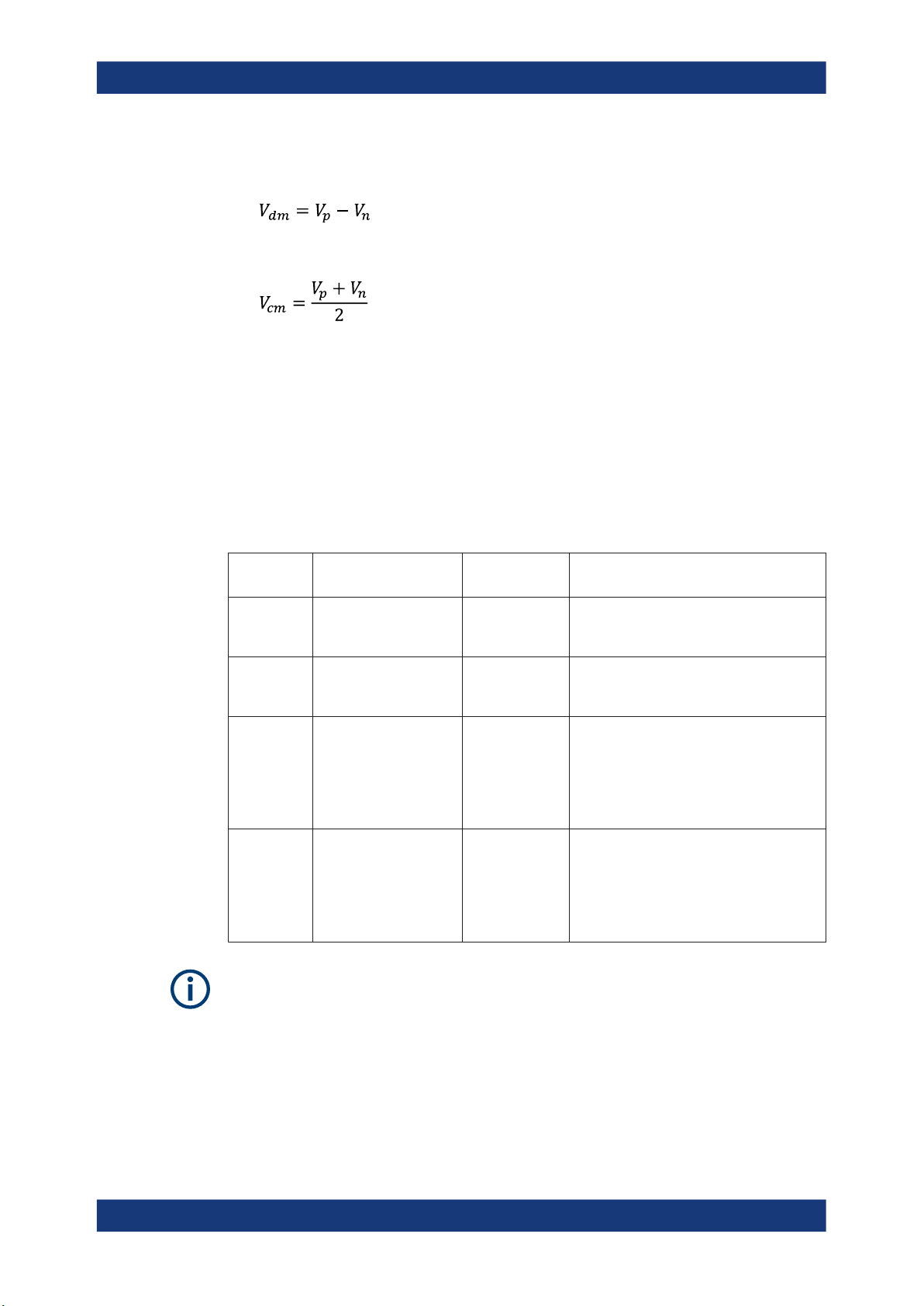
Four different input voltages can be measured with the MultiMode feature:
●
P-Mode: (pos.) Single-ended input voltage (Vp)
Voltage between the positive input terminal and ground
●
N-Mode: (neg.) Single-ended input voltage (Vn)
Voltage between the negative input terminal and ground
27User Manual 1179.4540.02 ─ 02
R&S®FSPN
Configuration
Configuring Data Inputs and Outputs
●
DM-Mode: Differential mode input voltage (Vdm)
Voltage between the positive and negative input terminal
●
CM-Mode: Common mode input voltage (Vcm)
Mean voltage between the positive and negative input terminal vs. ground
The R&S FSPN supports all probe modes. The mode is configured in the "Probe Set-
tings" on page 28.
Offset compensation
The R&S RT-ZM probes feature a comprehensive offset compensation function. The
compensation of DC components directly at the probe tip even in front of the active
probe amplifier is possible with an extremely wide compensation range of ±16 V (±24 V
for P and N modes).
The offset compensation feature is available for every MultiMode setting:
MultiMode
setting
DM-Mode Differential DC voltage ±16 V Probing single-ended signals, e.g. power
CM-Mode Common mode DC volt-
P-Mode DC voltage at positive
N-Mode DC voltage at negative
Offset compensation Offset compen-
sation range
±16 V Measurements of signals with high common
age
±24 V Measurement of single-ended AC signals
input terminal
±24 V Measurement of single ended AC signals
input terminal
Application
rails with high DC component and small AC
signal.
mode levels, e.g. current measurements
with a shunt resistor.
with high superimposed DC component at
the positive input terminal.
Note: The maximum voltage difference
between the positive and negative input terminals is 16 V.
with high superimposed DC component at
the negative input terminal.
Note: The maximum voltage difference
between the positive and negative input terminals is 16 V.
If the offset for DM-mode or CM-mode is changed, the offsets for the P-mode and Nmode are adapted accordingly, and vice versa.
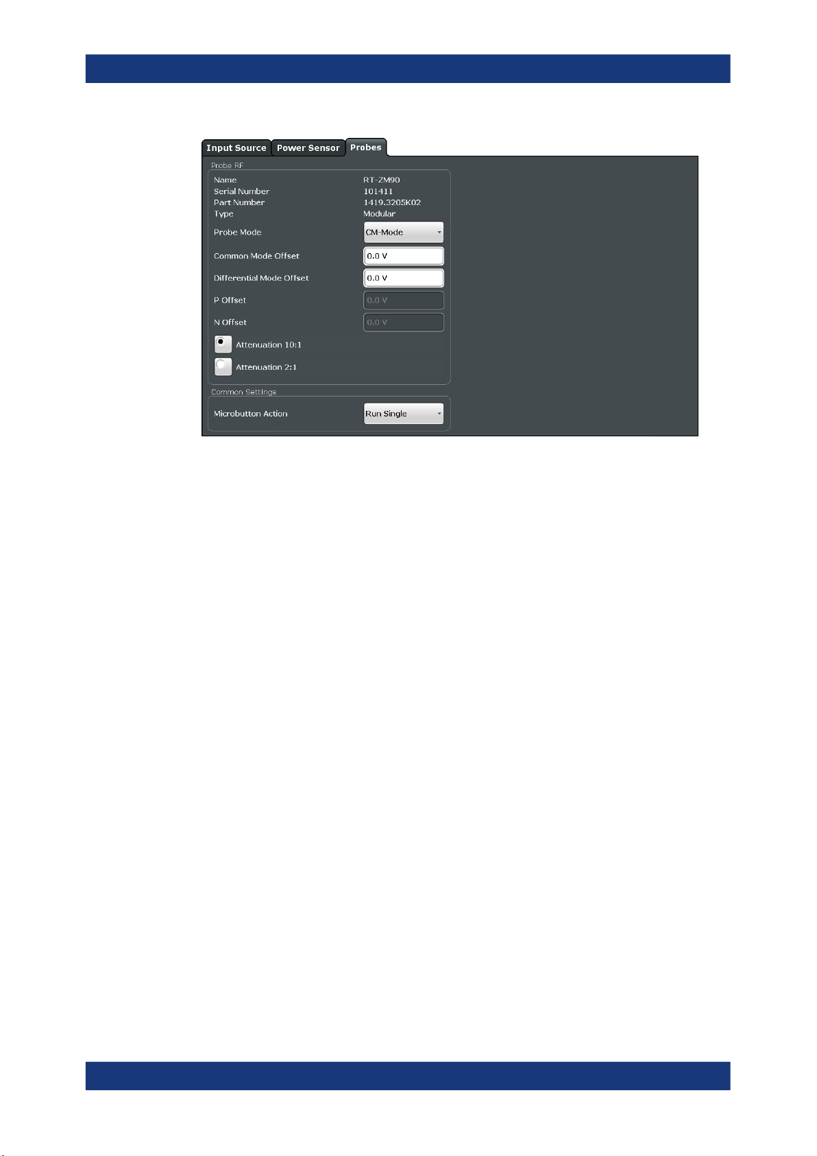
Probe Settings
Access: [INPUT / OUTPUT] > "Input Source Config" > "Probes"
Data input for the measurement can be provided by probes if the optional R&S RT-ZA9
adapter is used.
28User Manual 1179.4540.02 ─ 02
R&S®FSPN
Configuration
Configuring Data Inputs and Outputs
The detected type of probe, if any, is displayed.
For more information on using probes with an R&S FSPN, see "Using Probes"
on page 25.
For general information on the R&S®RT probes, see the device manuals.
Name.............................................................................................................................29
Serial Number............................................................................................................... 29
Part Number..................................................................................................................29
Type.............................................................................................................................. 30
Mode............................................................................................................................. 30
Common Mode Offset / Diff. Mode Offset / P Offset / N Offset /................................... 30
Attenuation....................................................................................................................30
Microbutton Action ....................................................................................................... 30
Name
Probe name
Remote command:
[SENSe:]PROBe<pb>:SETup:NAME? on page 134
Serial Number
Serial number of the probe
Remote command:
[SENSe:]PROBe<pb>:ID:SRNumber? on page 132
Part Number
Rohde & Schwarz part number
Remote command:
[SENSe:]PROBe<pb>:ID:PARTnumber? on page 132
29User Manual 1179.4540.02 ─ 02

R&S®FSPN
Configuration
Configuring Data Inputs and Outputs
Type
Type of probe:
●
Single-ended
●
Differential
●
Active Modular
Remote command:
[SENSe:]PROBe<pb>:SETup:TYPE? on page 136
Mode
Mode for multi-mode modular probes. Determines which voltage is measured.
"DM-mode"
"CM-mode"
"P-mode"
"N-mode"
Remote command:
[SENSe:]PROBe<pb>:SETup:PMODe on page 135
Voltage between the positive and negative input terminal
Mean voltage between the positive and negative input terminal vs.
ground
Voltage between the positive input terminal and ground
Voltage between the negative input terminal and ground
Common Mode Offset / Diff. Mode Offset / P Offset / N Offset /
Sets the offset for the probe, depending on the used mode (CM and DM mode both
use the "Common Mode Offset"). The setting is only available if a differential (R&S RTZD) or modular (R&S RT-ZM) probe is connected to the R&S FSPN.
If the probe is disconnected, the offset of the probe is reset to 0.0 V.
Note: If the offset for DM-mode or CM-mode is changed, the offsets for the P-mode
and N-mode are adapted accordingly, and vice versa.
Remote command:
[SENSe:]PROBe<pb>:SETup:CMOFfset on page 133
[SENSe:]PROBe<pb>:SETup:DMOFfset on page 133
[SENSe:]PROBe<pb>:SETup:NMOFfset on page 134
[SENSe:]PROBe<pb>:SETup:PMOFfset on page 136
Attenuation
Defines the attenuation applied to the input at the probe. This setting is only available
for modular probes.
"10:1"
"2:1"
Remote command:
[SENSe:]PROBe<pb>:SETup:ATTRatio on page 132
Attenuation by 20 dB
Attenuation by 6 dB
Microbutton Action
Active Rohde & Schwarz probes (except for R&S RT-ZS10E) have a configurable
microbutton on the probe head. By pressing this button, you can perform an action on
the instrument directly from the probe.
Select the action that you want to start from the probe:
"Run Single"
Starts one data acquisition.
30User Manual 1179.4540.02 ─ 02
 Loading...