


PAD-T-M: 3574.3259.02/01.00/CI/1/EN
R&S®FS-K73/K73+
3GPP FDD User Equipment Test
Software Manual
Software Manual
Test and Measurement
1154.7275.42 – 06

© 2014 Rohde & Schwarz GmbH & Co. KG
Muehldorfstr. 15, 81671 Munich, Germany
Phone: +49 89 41 29 - 0
Fax: +49 89 41 29 12 164
E-mail: info@rohde-schwarz.com
Internet: http://www.rohde-schwarz.com
Subject to change – Data without tolerance limits is not binding.
R&S® is a registered trademark of Rohde & Schwarz GmbH & Co. KG.
Trade names are trademarks of the owners.
The following abbreviations are used throughout this manual:
R&S®FS-K73/K73+ is abbreviated as R&S FS-K73/K73+

R&S FS-K73/K73+ Contents
Software Manual 1154.7275.42 - 06 3
Contents
1 3GPP FDD User Equipment Test - Application Firmware R&S FS-
K73/K73+ ............................................................................................. 7
2 Enabling the Firmware Option ........................................................... 8
3 Getting Started .................................................................................... 9
3.1 Basic Settings in Code Domain Measurement Mode .............................................10
3.2 Measurement 1: Measuring the Signal Power ........................................................10
3.3 Measurement 2: Measurement of Spectrum Emission Mask ................................11
3.4 Measurement 3: Measurement of Relative Code Domain Power ..........................11
3.4.1 Setting: Synchronizing the reference frequencies .......................................................12
3.4.2 Setting: Behaviour with Deviating Center Frequency Setting ......................................13
3.4.3 Setting: Behaviour with Incorrect Scrambling Code ....................................................13
3.5 Measurement 4: Triggered Measurement of Relative Code Domain Power ........14
3.5.1 Setting: Trigger offset ..................................................................................................14
3.6 Measurement 5: Measurement of Composite EVM ................................................15
3.7 Measurement 6: Measurement of Peak Code Domain Errors ...............................16
3.8 Measurement 7: Measurement of the Trigger To Frame Time ..............................17
3.8.1 Resolution of the TTF time measurement ...................................................................17
3.8.2 Absolute accuracy of the TTF time measurement .......................................................18
3.8.3 Trace statistic in the RESULT SUMMARY display ......................................................19
4 Setup for User Equipment Tests ..................................................... 20
4.1.1 Standard Test Setup ....................................................................................................20
4.1.2 Presetting .....................................................................................................................21
5 3GPP FDD Channel Configurations ................................................ 22
6 Menu Overview ................................................................................. 24
7 Configuration of 3GPP FDD Measurements ................................... 27
7.1 Measurement of Channel Power ..............................................................................28
7.2 Measurement of Adjacent-Channel Power - ACLR ................................................29
7.3 Signal Power Check – SPECTRUM EM MASK ........................................................38
7.4 Measurement of Occupied Bandwidth - OCCUPIED BANDWIDTH .......................41
7.4.1 Measurement of Signal Statistics ................................................................................44

R&S FS-K73/K73+ Contents
Software Manual 1154.7275.42 - 06 4
7.5 Code Domain Measurements on 3GPP FDD Signals .............................................48
7.5.1 Display modes – RESULTS hotkey .............................................................................50
7.5.2 Measurement Configuration –CHAN CONF hotkey ....................................................79
7.5.3 Configuration of CDP Measurement – SETTINGS hotkey ..........................................84
7.5.4 Frequenz-Einstellung – Key FREQ .............................................................................89
7.5.5 Span Settings – Key SPAN .........................................................................................90
7.5.6 Level Settings – Key AMPT .........................................................................................90
7.5.7 Marker Settings – Key MKR ........................................................................................91
7.5.8 Changing Instrument Settings – Key MKR
...............................................................93
7.5.9 Marker Functions – Key MKR FCTN ...........................................................................94
7.5.10 Bandwidth Setting – Key BW .......................................................................................94
7.5.11 Measurement Control – Key SWEEP ..........................................................................94
7.5.12 Measurement Selection – Key MEAS..........................................................................94
7.5.13 Trigger Settings – Key TRIG ........................................................................................94
7.5.14 Trace-Einstellungen – Key TRACE ............................................................................95
7.5.15 Display-Lines – Key LINES .........................................................................................97
7.5.16 Settings of Measurement Screen – Key DISP .............................................................97
7.5.17 Storing and Loading of Unit Data – Key FILE ..............................................................98
8 Remote-Control Commands ............................................................ 99
8.1 CALCulate – Subsystem ..........................................................................................99
8.1.1 CALCulate:FEED – Subsystem ...................................................................................99
8.1.2 CALCulate:LIMit – Subsystem ...................................................................................101
8.1.3 CALCulate:MARKer – Subsystem .............................................................................108
8.1.4 CALCulate:PEAKsearch – Subsystem ......................................................................109
8.1.5 CALCulate:STATistics - Subsystem ..........................................................................110
8.2 CONFigure:WCDPower Subsystem .......................................................................112
8.3 DISPlay - Subsystem ...............................................................................................117
8.4 INSTrument Subsystem ..........................................................................................118
8.5 SENSe - Subsystem ................................................................................................118
8.5.1 SENSe:CDPower Subsystem ....................................................................................118
8.5.2 SENSe:POWer - Subsystem .....................................................................................124
8.6 STATus-QUEStionable:SYNC Register .................................................................131
8.7 TRACe Subsystem ...................................................................................................133
8.8 Table of Softkeys with Assignment of IEC/IEEE Commands ..............................140
9 Performance Test ........................................................................... 148
9.1 Required Measuring Equipment and Accessories ...............................................148

R&S FS-K73/K73+ Contents
Software Manual 1154.7275.42 - 06 5
9.2 Test Procedure .........................................................................................................149
10 Glossary .......................................................................................... 151
11 Index ................................................................................................ 153


R&S FS-K73/K73+ 3GPP FDD User Equipment Test - Application Firmware R&S FS-K73/K73+
Software Manual 1154.7275.42 - 06 7
1 3GPP FDD User Equipment Test -
Application Firmware R&S FS-K73/K73+
The Spectrum Analyzer R&S FSP, R&S FSU, Signal Analyzer R&S FSQ or Measuring
Receiver R&S FSMR equipped with Application Firmware R&S FS-K73 perform code
domain power measurements on uplink signals according to standard 3GPP (FDD
mode). The application firmware is in line with standard 3GPP (Third Generation
Partnership Project) with version Release 5. In addition to the code domain
measurements prescribed by the standard 3GPP, the application offers measurements
with predefined settings in the frequency domain, e.g. power and ACLR measurement.
The Application Firmware R&S FS-K73+ additionally allows measurements according
to Release 7 including EDPDCH channels with modulation format 4PAM. R&S FS-K73
must be installed before installing R&S FS-K73+ on the R&S Analyzer

R&S FS-K73/K73+ Enabling the Firmware Option
Software Manual 1154.7275.42 - 06 8
2 Enabling the Firmware Option
Firmware Option R&S FS-K73 is enabled in the GENERAL SETUP menu by entering a
keyword. The keyword is delivered with the option. R&S FS-K73 and R&S FS-K73+
have different keywords. R&S FS-73 must be installed before R&S FS-K73+ is
installed. If one option is factory-installed, it is already enabled.
GENERAL SETUP menu
OPTIONS
The OPTIONS softkey opens a submenu where keywords for new firmware options
(application firmware modules) can be entered. Available options are displayed in a
table, which is opened when entering the submenu.
INSTALL OPTION
The INSTALL OPTION softkey activates the entry of the keyword for a firmware option.
One ore several keywords can be entered in the entry field. On entering a valid
keyword, OPTION KEY OK is displayed on the message line and the option is entered
in the FIRMWARE OPTIONS table.
In case of invalid keywords, OPTION KEY INVALID is displayed on the message line.

R&S FS-K73/K73+ Getting Started
Software Manual 1154.7275.42 - 06 9
3 Getting Started
[<KEY>]
Press a key on the front panel, e.g. [SPAN]
[<SOFTKEY>]
Press a softkey, e.g. [MARKER -> PEAK]
[<nn unit>]
Enter a value and terminate by entering the unit, e.g. [12 kHz]
[<KEY>]
Press a key on the front panel, e.g. [FREQ]
<MENÜ>
Select a menu, parameter or a setting, e.g. DIGITAL STD.
The menu level is marked by an indentation.
<nn unit>
Enter a value and terminate by entering the unit, e.g. 12 kHz
The following chapter explains basic 3GPP FDD user equipment tests by means of a
setup with signal generator R&S SMIQ. It describes how operating and measurement
errors can be avoided using correct presetting.
The measurement screen is presented in chapter 6 for each measurement.
Key settings are shown as examples to avoid measurement errors. Following the
correct setting, the effect of an incorrect setting is shown. The following measurements
are performed:
Measurement 1: Measuring the spectrum
Measurement 2: Measurement of spectrum emission mask
Measurement 3: Measurement of relative code domain power r
o Setting: Setting the analyzer center frequency to the DUT
frequency
o Setting: Scrambling code of signal
Measurement 4: Triggered measurement of relative code domain power
o Setting: Trigger offset
Measurement 5: Measurement of composite EVM
Measurement 6: Measurement of peak code domain erro
The measurements are performed using the following units and accessories:
R&S Analyzer with Application Firmware R&S FS-K73: 3GPP FDD user
equipment test.
Vector Signal Generator R&S SMIQ with option R&S SMIQB45: digital
standard 3GPP
(options R&S SMIQB20 and R&S SMIQB11 required)
1 coaxial cable, 50 , approx. 1 m, N connector
1 coaxial cable, 50 , approx. 1 m, BNC connector
Conventions for displaying settings on R&S Analyzer:
Conventions for displaying settings on R&S SMIQ:
R&S FS-K73/K73+ Getting Started
Software Manual 1154.7275.42 - 06 10
3.1 Basic Settings in Code Domain Measurement Mode
Parameter
Setting
Digital standard
W-CDMA 3GPP REV
Sweep
CONTINUOUS
CDP mode
CODE CHAN AUTOSEARCH
Trigger settings
FREE RUN
Trigger offset
0
Scrambling code
0
Threshold value
-60 dB
Symbol rate
15 ksps
Code number
0
Slot number
0
I/Q branch
Q
Display
Screen A: CODE PWR RELATIVE
Screen B: RESULT SUMMARY
Test setup
► Connect the RF output of R&S SMIQ to the RF input of R&S Analyzer
(coaxial cable with N connectors).
Settings on R&S
SMIQ:
[PRESET]
[LEVEL: 0 dBm]
[FREQ: 2.1175 GHz]
DIGITAL STD
WCDMA/3GPP
SET DEFAULT
LINK DIRECTION UP/REVERSE
TEST MODELS (NOT STANDARDIZED)...
C+D960K
STATE: ON
Settings on R&S
Analyzer:
[[PRESET]
[CENTER: 2.1175 GHz]
[AMPT: 0 dBm]
[3G FDD UE]
[MEAS: POWER]
Measurement on
The following is displayed:
In the default setting after PRESET, the R&S Analyzer is in the analyzer mode. The
following default settings of the code domain measurement are activated, provided the
code domain measurement mode is selected.
Table 3-1: Default settings of the code domain measurement
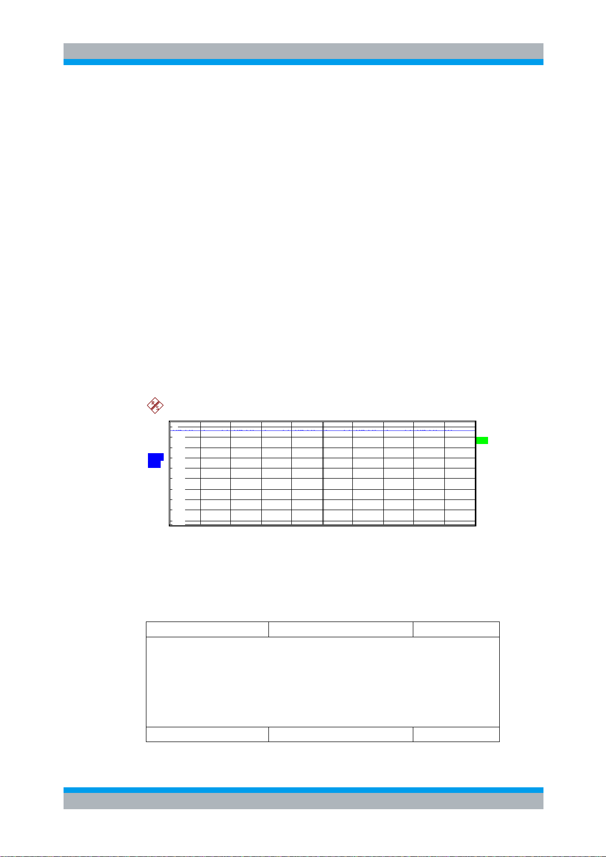
3.2 Measurement 1: Measuring the Signal Power
The measurement of the spectrum gives an overview of the 3GPP FDD signal and the
spurious emissions close to the carrier.

R&S FS-K73/K73+ Getting Started
Software Manual 1154.7275.42 - 06 11
R&S Analyzer:
Spectrum of the 3GPP FDD signal
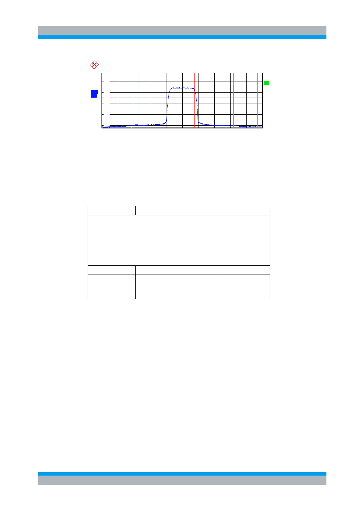
3.3 Measurement 2: Measurement of Spectrum Emission
Test setup
► Connect the RF output of R&S SMIQ to the RF input of R&S Analyzer (coaxial
cable with N connectors).
Settings on R&S
SMIQ:
[PRESET]
[LEVEL: 0 dBm]
[FREQ: 2.1175 GHz]
DIGITAL STD
WCDMA/3GPP
SET DEFAULT
LINK DIRECTION UP/REVERSE
TEST MODELS (NOT STANDARDIZED)...
C+D960K
STATE: ON
Settings on R&S
Analyzer:
PRESET]
[CENTER: 2.1175 GHz]
[AMPT: 0 dBm]
[3G FDD UE]
[MEAS: SPECTRUM EM MASK]
Measurement on
R&S Analyzer:
The following is displayed:
Spectrum of the 3GPP FDD signal
Limit line defined in the standard
Information on limit line violations (passed/failed)
Settings on R&S
SMIQ:
► Connect the RF output of R&S SMIQ to the input of R&S Analyzer
► Connect the reference input (EXT REF IN/OUT) on the rear panel of the
Mask
The 3GPP specification defines a measurement, which monitors the compliance with a
spectral mask in a range of at least 12.5 MHz about the 3GPP FDD carrier. To
assess the power emissions in the specified range, the signal power is measured in
the range near the carrier by means of a 30kHz filter, in the ranges far off the carrier by
means of a 1MHz filter. The resulting trace is compared to a limit line defined in the
3GPP specification.
3.4 Measurement 3: Measurement of Relative Code Domain Power
A code domain power measurement on one of the channel configurations is shown in
the following. Basic parameters of CDP analysis are changed to demonstrate the
effects of non-signal-adapted values.

R&S FS-K73/K73+ Getting Started
Software Manual 1154.7275.42 - 06 12
analyzer to the reference input (REF) on the rear panel of R&S SMIQ (coaxial
cable with BNC connectors).
Settings on R&S
SMIQ:
[PRESET]
[LEVEL: 0 dBm]
[FREQ: 2.1175 GHz]
DIGITAL STD
WCDMA 3GPP
LINK DIRECTION UP/REVERSE
TEST MODELS (NOT STANDARDIZED)...
C+D960K
SELECT BS/MS
MS 1 ON
OVERALL SYMBOL RATE...6*960
STATE: ON
Settings on R&S
Analyzer:
[[PRESET]
[CENTER: 2.1175 GHz]
[AMPT: 10 dBm]
[3G FDD UE]
[SETTINGS: SCRAMBLING CODE 0]
Measurement on
R&S Analyzer:
The following is displayed:
● Screen A: Code domain power of signal, branch Q
(channel configuration with 3 data channels on Q branch)
● Screen B: Numeric results of CDP measurement
Test setup
► Connect the reference input (EXT REF IN/OUT) on the rear panel of the
analyzer to the reference output (REF) on the rear panel of R&S SMIQ (coaxial
cable with BNC connectors).
Settings on R&S
SMIQ:
As for measurement 2
Settings on R&S
Analyzer:
As for measurement 2, plus
[[SETUP: REFERENCE EXT]
Measurement on
R&S Analyzer:
Frequency error The displayed frequency error should be < 10 Hz.
3.4.1 Setting: Synchronizing the reference frequencies
The synchronization of the reference oscillators both of the DUT and analyzer strongly
reduces the measured frequency error.
The reference frequencies of the analyzer and of the DUT should be
synchronized

R&S FS-K73/K73+ Getting Started
Software Manual 1154.7275.42 - 06 13
3.4.2 Setting: Behaviour with Deviating Center Frequency Setting
Settings on R&S
SMIQ:
► Tune the center frequency of the signal generator in 0.5 kHz steps and watch
the analyzer screen:
Measurement on
R&S Analyzer:
A CDP measurement on the analyzer is still possible with a frequency error of
up to approx. 1 kHz. Up to 1 kHz, a frequency error causes no apparent
difference in measurement accuracy of the code domain power measurement.
Above a frequency error of 1 kHz, the probability of an impaired
synchronization increases. With continuous measurements, at times all
channels are displayed in blue with almost the same level.
Above a frequency error of approx. 2 kHz, a CDP measurement cannot be
performed. R&S Analyzer displays all possible codes in blue with a similar level
Settings on R&S
SMIQ:
► Set the signal generator center frequency again to 2.1175 GHz:
[FREQ: 2.1175 GHz]
Settings on R&S SMIQ
SELECT BS/MS
BS 1: ON
SCRAMBLING CODE: 0001
(the scrambling code is set to 0000 on the analyzer)
Measurement on R&S
Analyzer:
The CDP display shows all possible codes with approximately the same level.
Settings on R&S
Analyzer:
Set scrambling code to new value:
[SETTINGS: SCRAMBLING CODE 1]
Measurement on R&S
Analyzer:
The CDP display again shows the channel configuration.
In the following, the behaviour of the DUT and the analyzer with wrong center
frequency setting is shown.
The analyzer center frequency should not differ from the DUT frequency by more than
2 kHz.
3.4.3 Setting: Behaviour with Incorrect Scrambling Code
A valid CDP measurement can only be carried out if the scrambling code set on the
analyzer is identical to the one of the transmitted signal.
The scrambling code setting of the analyzer must be identical to that of the measured
signal.

R&S FS-K73/K73+ Getting Started
Software Manual 1154.7275.42 - 06 14
3.5 Measurement 4: Triggered Measurement of Relative Code
Test setup
► Connect the RF output of R&S SMIQ to the input of R&S Analyzer
► Connect the reference input (EXT REF IN/OUT) on the rear panel of R&S
Analyzer to the reference input (REF) on the rear panel of R&S SMIQ (coaxial
cable with BNC connectors).
► Connect the external trigger input on the rear panel of R&S Analyzer (EXT TRIG
GATE) to the external trigger output on the rear panel of R&S SMIQ (TRIGOUT1
of PAR DATA).
Settings on R&S
SMIQ:
As for measurement 3
Settings on R&S
Analyzer:
As for measurement 3, plus
[TRIG EXTERN]
Measurement on
R&S Analyzer:
The following is displayed:
Screen A: Code domain power of signal
(channel configuration with 3 data channels on Q branch)
Screen B: Numeric results of CDP measurement
Trg to Frame: Offset between trigger event and start of 3GPP FDD frame
The repetition rate of the measurement increases considerably compared to the
repetition rate of a measurement without external trigger.
Settings on R&S
Analyzer:
[TRIG: TRIGGER OFFSET 100 s ]
Measurement on R&S
Analyzer:
The parameter Trg to Frame in the numeric results table (screen B)
changes:
Trigger to Frame -100 s
Domain Power
If the code domain power measurement is performed without external triggering, a
section of approximately 20 ms of the test signal is recorded at an arbitrary moment to
detect the start of a 3GPP FDD frame in this section. Depending on the position of the
frame start, the required computing time can be quite long. Applying an external
(frame) trigger can reduce the computing time.
3.5.1 Setting: Trigger offset
A delay of the trigger event referred to the start of the 3GPP FDD frame can be
compensated by modifying the trigger offset.
A trigger offset compensates analog delays of the trigger event.

R&S FS-K73/K73+ Getting Started
Software Manual 1154.7275.42 - 06 15
3.6 Measurement 5: Measurement of Composite EVM
Test setup
► Connect the RF output of R&S SMIQ to the input of R&S Analyzer.
► Connect the reference input (EXT REF IN/OUT) on the rear panel of R&S
Analyzer to the reference input (REF) on the rear panel of R&S SMIQ
(coaxial cable with BNC connectors).
► Connect the external trigger input on the rear panel of R&S Analyzer (EXT
TRIG GATE) to the external trigger output on the rear panel of R&S SMIQ
(TRIGOUT1 of PAR DATA).
Settings on R&S SMIQ:
[PRESET]
[LEVEL: 0 dBm]
[FREQ: 2.1175 GHz]
DIGITAL STD
LINK DIRECTION UP / REVERSE
TEST MODELS (NOT STANDARDIZED)..
C+D960K
SELECT BS/MS
MS 1 ON
OVERALL SYMBOL RATE... 6*960
STATE: ON
Settings on R&S
Analyzer:
[[PRESET]
[CENTER: 2.1175 GHz]
[REF: 10 dBm]
[3G FDD UE]
[TRIG EXTERN]
[RESULTS COMPOSITE EVM]
Measurement on R&S
Analyzer:
The following is displayed:
Screen A: Code domain power of signal, branch Q
(channel configuration with 3 data channels on branch Q)
Screen B: Composite EVM (EVM for total signal)
The 3GPP specification prescribes the composite EVM measurement as the average
square deviation of the total signal:
An ideal reference signal is generated from the demodulated data. The test signal and
the reference signal are compared with each other. The square deviation yields the
composite EVM.

R&S FS-K73/K73+ Getting Started
Software Manual 1154.7275.42 - 06 16
3.7 Measurement 6: Measurement of Peak Code Domain
Test setup
► Connect the RF output of R&S SMIQ to the input of R&S Analyzer
► Connect the reference input (EXT REF IN/OUT) on the rear panel of R&S
Analyzer to the reference input (REF) on the rear panel of R&S SMIQ (coaxial
cable with BNC connectors).
► Connect the external trigger input on the rear panel of R&S Analyzer (EXT TRIG
GATE) to the external trigger output on the rear panel of R&S SMIQ (TRIGOUT1
of PAR DATA).
Settings on R&S
SMIQ:
[PRESET]
[LEVEL: 0 dBm]
[FREQ: 2.1175 GHz]
DIGITAL STD
WCDMA 3GPP
LINK DIRECTION UP / REVERSE
TEST MODELS (NOT STANDARDIZED)...
C+D960K
SELECT BS/MS
MS 1 ON
OVERALL SYMBOL RATE... 6*960
STATE: ON
Settings on R&S
Analyzer:
PRESET]
[CENTER: 2.1175 GHz]
[REF: 0 dBm]
[3G FDD UE]
[TRIG EXTERN]
[RESULTS PEAK CODE DOMAIN ERR]
SPREAD FACTOR 256]
Measurement on
R&S Analyzer:
The following is displayed:
Screen A: Code domain power of signal, branch Q
(channel configuration with 3 data channels on branch Q).
Screen B: Peak code domain error (projection of the error onto the class with
spreading factor 256.
Errors
The peak code domain error measurement is defined in the 3GPP specification for
FDD signals.
An ideal reference signal is generated from the demodulated data. The test signal and
the reference signal are compared with each other. The difference of the two signals is
projected onto the classes of the different spreading factors. The peak code domain
error measurement is obtained by summing up the symbols of each difference signal
slot and searching for the maximum error code.

R&S FS-K73/K73+ Getting Started
Software Manual 1154.7275.42 - 06 17
3.8 Measurement 7: Measurement of the Trigger To Frame
Test setup:
► Connect the RF output of R&S SMIQ to the input of R&S Analyzer (coaxial cable
with N connectors).
► Connect the reference input (EXT REF IN/OUT) on the rear panel of R&S
Analyzer to the reference input (REF) on the rear panel of R&S SMIQ (coaxial
cable with BNC connectors)
► Connect the external trigger input on the rear panel of R&S Analyzer (EXT TRIG
GATE) to the external trigger output on the rear panel of R&S SMIQ (TRIGOUT1
of PAR DATA).
Settings on
R&S SMIQ:
[PRESET]
[LEVEL: 0 dBm]
[FREQ: 2.1175 GHz]
DIGITAL STD
WCDMA 3GPP
TEST MODELS ...
TEST1_32
STATE: ON
Settings on
R&S Analyzer:
[PRESET]
[CENTER: 2.1175 GHz]
[REF: 0 dBm]
[3G FDD BS]
[TRIG EXTERN]
[RESULTS RESULT SUMMARY]
[SCREEN SCREEN B]
[TRACE: AVERAGE]
[ CLEAR / WRITE]
[SWEEP COUNT] <numeric value>
Measurement on
R&S Analyzer:
The following is displayed:
Screen A: Code domain power of signal
(Test-Modell 1 mit 32 Kanälen)
Screen B: Result-Summary with Trace-Statistik-Messunge
Time
The trigger to frame (TTF) time measurement yields the time between an external
trigger event and the start of the 3GPP WCDMA frame. The result is diplayed in the
result summary. The trigger event is expected in a time range of one slot (667us)
before the frame start. The resolution and absolute accuracy depend on the analyzer
type and the measurement mode.
3.8.1 Resolution of the TTF time measurement
The resolution of the TTF time depends on the analyzer type that is used and the
applied trace statistic mode. By using an average mode, the resolution can be
increased. The higher the number of sweeps, the higher the resolution at the expense
of measurement time. In the average mode, the TTF time is averaged for a number of

R&S FS-K73/K73+ Getting Started
Software Manual 1154.7275.42 - 06 18
sweeps (TRACESWEEP COUNT). If the TTF time of the applied signal does not
Analyzer
Trace mode
TTF resolution
Number
of sweeps
R&S - FSQ
CLEAR/WRITE
< 8 ns
1
R&S - FSQ
AVERAGE
< 0.5 ns
100
R&S - FSU
CLEAR/WRITE
< 65 ns
1
R&S - FSU
AVERAGE
< 4 ns
100
R&S - FSP
CLEAR/WRITE
< 65 ns
1
R&S - FSP
AVERAGE
< 4 ns
100
2 3 4 5 6 7 8 9 10
-80
-60
-40
-20
0
20
40
Trigger Level [V]
Absolute error of Trigger to Frame time [ns]
Absolute error of Trigger to Frame time measurement versus Trigger Level
Curve of absolute Trigger to Frame time error
Tolerance curve for FSQ (AVG mode)
Tolerance curve for FSQ (CLR/WRT mode) FSU (AVG mode)
change during for this number of sweeps, the trigger resolution can be improved.
TTF time resolution in dependency of the analyzer type and the statistic mode:
3.8.2 Absolute accuracy of the TTF time measurement
The absolute accuracy of the TTF time measurement depends on the level of the
trigger pulse. The analyzer is calibrated to display the minimum deviation at a trigger
pulse level of 4 V. The trigger threshold for an external trigger event is 1.4 V. Due to an
internal lowpass between the back panel and the trigger detector, the trigger pulse is
delayed in correlation to its own level
The absolute error of the TTF time measurement as a function of the trigger level is as
follows:
The dash-dotted curve shows the error of the TTF measurement. The dashed and
solid curves indicate the expected measurement uncertainty depending on the

R&S FS-K73/K73+ Getting Started
Software Manual 1154.7275.42 - 06 19
analyzer type used and the applied trace statistic. To calculate the accurate TTF time,
ErrorAnalyserMeasTrgToFrame
TTT
_
CLEAR/WRITE:
Displays the result value of the last sweep
(<none>)
MAX HOLD:
Displays the maximum result values of a
number of sweeps
(<MAX>)
MIN HOLD:
Displays the minimum result value of a number
of sweeps
(<MIN>)
AVERAGE:
Displays the average result value of a number of
sweeps
(<AVG>)
TRACE
SCREEN B
CLEAR/
WRITE
MAX HOLD
MIN HOLD
AVERAGE
the error needs to be subtracted from the measured TTF value:
where: T
TrgToFrame
correct TTF time
T
meas_Analyzer
TTF time displayed by the analyzer (display RESULT
SUMMARY)
T
absolute error
error
3.8.3 Trace statistic in the RESULT SUMMARY display
The trace statistic functions can be enabled by selecting SCREEN B. After screen B is
selected, the trace menu can be called (press hardkey TRACE). In the trace menu, the
kind of trace statistic can be selected.
The parameter SWEEP COUNT determines the number of sweeps. The result values
in the result summary of screen B are tagged with an abbreviation to indicate which
kind of trace statistic is applied to the results. If measured with the trace statistic, the
channel table is automatically switched to predefined mode. The last measured
channel table is used and stored to "RECENT". In this case, any change in the signal
channel configuration does not influence the displayed channel table.
The following trace statistic functions can be applied and are tagged with the
corresponding abbreviations shown in the last column:

R&S FS-K73/K73+ Setup for User Equipment Tests
Software Manual 1154.7275.42 - 06 20
4 Setup for User Equipment Tests
Non-compliance with these instructions may cause damage to the instrument.
● Before turning the instrument on, the following conditions must be fulfilled:
● Instrument covers are in place and all fasteners are tightened.
● Fan openings are free from obstructions.
● Signal levels at the input connectors are all below specified maximum values.
● Signal outputs are correctly connected and not overloaded.
0
1 2 3
4 5 6
7 8 9
. -
ESC
1129.9003.03
FCTN
ENTER
CANCEL
MEAS TRI G
FREQ
MKR
AMPTSPAN
MKR
MKR
BW SWEEP
TRACE
LINES
DISP
FILE
GHz
MHz
kHz
Hz
-dBm
dBm
dB
dB..
CAL
SETUP
PRESET
HCOPY
SPECTRUM ANALYZER 20Hz . . . 3.6GHz
..
FSU
BACK
s
V
ms
mV
µs
µV
ns
nV
PREV NEXT
MADE IN GERMANY
.
POWER SENSOR
GEN OUTPUT 50
AF OUTPUT
RF INPUT
50
EXT MIXER
LO OUT/ IF IN IF IN
MAX+30 dBm / 0V DC
KEYBOARD
MAX 0V DC
PROBE POWER
I IN
Q IN
NOISE SOURCE
RF
INPUT
TX signal
2
DEF
3
GHI
1
ABC
5 64
8
ÜVW7STU
.-0
9
XYZ
S CRCL M
Max. power
Recommended ext. attenuation
55 to 60 dBm
35 to 40 dB
50 to 55 dBm
30 to 35 dB
45 to 50 dBm
25 to 30 dB
40 to 45 dBm
20 to 25 dB
35 to 40 dBm
15 to 20 dB
This section describes how to set up the analyzer for 3GPP FDD user equipment tests.
As a prerequisite for starting the test, the instrument must be correctly set up and
connected to the AC power supply as described in chapter 1 of the operating manual
for the analyzer. Furthermore, the application firmware module must be properly
installed following the instructions given in chapter 1 of the present manual.
4.1.1 Standard Test Setup
Figure 4-1: UE test setup
► Connect antenna output (or TX output) of UE to RF input of the analyzer via a
power attenuator of suitable attenuation.
The following values are recommended for the external attenuator to ensure that
the RF input of the analyzer is protected and the sensitivity of the analyzer is not
reduced too much:

R&S FS-K73/K73+ Setup for User Equipment Tests
Software Manual 1154.7275.42 - 06 21
30 bis 35 dBm
10 bis 15 dB
25 bis 30 dBm
5 bis 10 dB
20 bis 25 dBm
0 bis 5 dB
< 20 dBm
0 dB
► For signal measurements at the output of two-port networks, connect the reference
frequency of the signal source to the rear reference input of the analyzer (EXT
REF IN/OUT).
To ensure that the error limits specified by the 3GPP standard are met, the
analyzer should use an external reference frequency for frequency measurements
on user equipments. A rubidium frequency standard may be used for instance as a
reference source.
► If the user equipment is provided with a trigger output, connect this output to the
rear trigger input of the analyzer (EXT TRIG GATE).
4.1.2 Presetting
► Enter external attenuation (REF LVL OFFSET).
► Enter reference level.
► Enter center frequency.
► Set the trigger.
► Select standard and measurement.

R&S FS-K73/K73+ 3GPP FDD Channel Configurations
Software Manual 1154.7275.42 - 06 22
5 3GPP FDD Channel Configurations
Channel type
Number of
channels
Symbol rate
Spreading code(s)
Mapping to
component
DPCCH
1
15 ksps
0 Q DPDCH
1
15 ksps – 960 ksps
[Spreading-Faktor / 4]
I
Channel type
Number of
channels
Symbol rate
Spreading code(s)
Mapping to
component
DPCCH
1
15 ksps
0 Q DPDCH
1
960 ksps
1 I DPDCH
1
960 ksps
1
Q
DPDCH
1
960 ksps
3 I DPDCH
1
960 ksps
3 Q DPDCH
1
960 ksps
2 I DPDCH
1
960 ksps
2
Q
Number of
DPDCH
Symbol rate
all DPDCH
Symbol rate
HS-DPCCH
Spreading code
HS-DPCCH
Mapping to component
(HS-DPCCH)
1
15 – 960 ksps
15 ksps
64 Q 2
1920 ksps
15 ksps
1 I 3
2880 ksps
15 ksps
32
Q
4
3840 ksps
15 ksps
1
I
5
4800 ksps
15 ksps
32 Q 6
5760 ksps
15 ksps
1
I
The possible channel configurations for the mobile station signal are limited by 3GPP.
Only two different configurations for data channels DPDCH are permissible according
to the specification. In addition to these two channel configurations the transmission of
channel HS-DPCCH is permissible for operating the mobile station in mode HSDPA.
For this reason, the R&S FS-K73 checks for these channel configurations only during
the automatic channel search. Therefore, channels whose parameters do not
correspond to one of these configurations are not automatically detected as active
channels.
The two possible channel configurations are summarized below:
Table 5-1: Channel configuration 1: DPCCH and 1 DPDCH
Table 5-2: Channel configuration 2: DPCCH and up to 6 DPDCH
Table 5-3: Channel configuration 3: DPCCH, up to 6 DPDCH and 1 HS-DPCCH
In addition to the channel configurations shown above in table 4-2, one HS-DPCCH
can be added to each channel table.

R&S FS-K73/K73+ 3GPP FDD Channel Configurations
Software Manual 1154.7275.42 - 06 23
Table 5-4: Kanalkonfiguration 4: DPCCH, bis zu 1 DPDCH, 1E-DPCCH, bis zu 4 E-DPDCH
Number of DPDCH
E-DPDCHk
Spreading code E-DPDCH
0
E-DPDCH1
Cch,SF,SF/4 if SF 4
Cch,2,1 if SF = 2
E-DPDCH2
Cch,4,1 if SF = 4
Cch,2,1 if SF = 2
E-DPDCH3
E-DPDCH4
Cch,4,1
1
E-DPDCH1
Cch,SF,SF/2
E-DPDCH2
Cch,4,2 if SF = 4
Cch,2,1 if SF = 2
When more than one E-DPDCH is transmitted, the respective channelisation codes
used for E-DPDCH1 and E-DPDCH2 are always the same
The E-DPCCH is always spread with channelisation code 1 at symbol rate 15 ksps.
The number of E-DPDCH channels depends on the number of DPDCH channels: If
there is no DPDCH configur.ed, the signal can contain up to 4 E-DPDCH channels. If
there is one DPDCH configured, only up to 2 E-DPDCH channels are possible.
E-DPDCHk shall be spread with channelisation code c
on N
max-dpdch
and the spreading factor selected for the corresponding frame or sub-
. The sequence c
ed,k
frame as specified in [7]; it shall be selected according to table 1E.
depends
ed,k

R&S FS-K73/K73+ Menu Overview
Software Manual 1154.7275.42 - 06 24
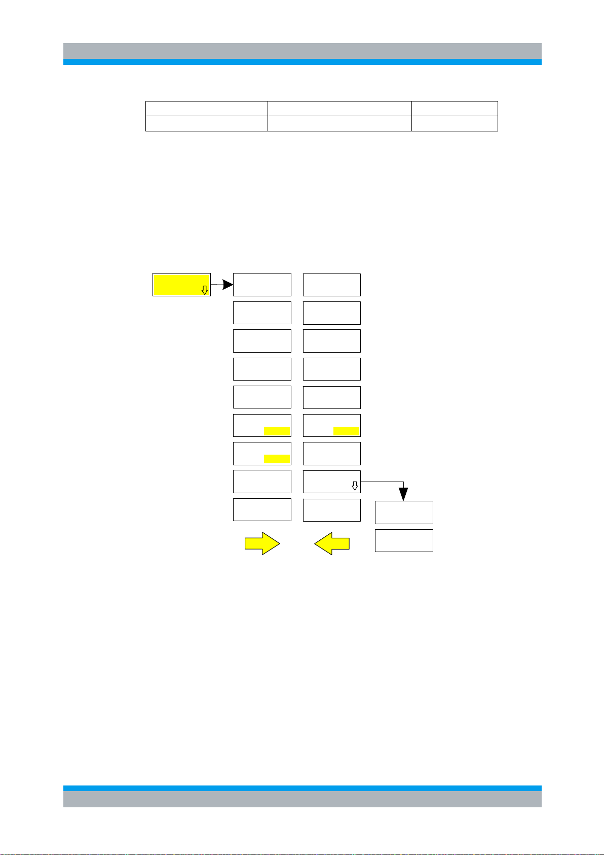
6 Menu Overview
SPECTRUM SCREEN B3G FDD UE
Application Firmware Module R&S FS-K73 (3GPP FDD user equipment test) extends
the analyzer by the code domain measurement mode for 3GPP FDD standard.
Additional softkeys are available which allow overview measurements in the analyzer
mode.
The R&S FS-K73 application is started by a click on the 3G FDD UE hotkey:
The main settings of the code domain power measurements can be directly selected
via the hotkey bar that changes after the application has been started.
When one of the CHAN CONF, SETTINGS, RESULTS hotkeys is selected, the
measurement is automatically switched to the Code Domain Power measurement
mode.
If the EXIT 3GPP hotkey is selected, R&S FS-K73 is exited. The hotkey bar of the basic
unit is displayed again.

R&S FS-K73/K73+ Menu Overview
Software Manual 1154.7275.42 - 06 25
EVM
COMPOSITE
SIGNAL
COMPOSITE
VS SLOT
POWER
RESULT
SUMMARY
CHANNEL
SELECT
REF LVL
ADJUST
CODE DOM
POWER
SELECT
I Q
CODE DOM
ERROR
CHANNEL
TABLE
CHANNEL
SELECT
REF LVL
ADJUST
SELECT
I Q
CONST
SYMBOL
BITSTREAM
REF LVL
ADJUST
CHANNEL
SELECT
SELECT
I Q
RESULTS SCREEN B
SELECT
CHANNEL
SELECT
SLOT
ADJUST
REF LVL
CAPTURE
LENGTH
FRAME TO
ANALYZE
SELECT
I Q
POWER
VS SYMBOL
CODE PWR
OVERVIEW
SYMBOL
EVM
EVM
SYMBOL
SELECT
SELECT
SELECT
VS SLOT
FREQ ERR
DISCONT
PHASE
ERROR
SYMB MAG
ERROR
SYMB PHASE
MAG ERROR
VS CHIP
EVM
VS CHIP
VS CHIP
PHASE ERR
CONST
COMPOSITE
DOMAIN ERR
PEAK CODE
HEADER
VALUES
MEAS CHAN
CONF TABLE
SAVE TABLE
CODE CHAN
AUTOSEARCH
CODE CHAN
PREDEFINED
NEW CHAN
CONF TABL
EDIT CHAN
CONF TABL
DEL CHAN
CONF TABL
COPY CHAN
CONF TABL
SCRAMBLING
CODE
CODE PWR
ABS REL
MEASURE
SLOT FRAME
SCR TYPE
LONG SHRT
SIDE BAND
NORM INV
NORMALIZE
ON OFF
MULTI FRM
CAPTURE
SELECT
CHANNEL
SELECT
SLOT
ADJUST
REF LVL
CAPTURE
LENGTH
FRAME TO
ANALYZE
SETTINGSCHAN CONFEXIT 3GPP
SELECT
I Q
RRC FILTER
ON OFF
ELIMINATE
TAIL CHIPS
SCRAMBLING
CODE
FORMAT
HEX DEC
HS-DPA/UPA
ON OFF
Figure 6-1: Overview of menus of code domain power
The measurements available in R&S FS-K73 can be selected by means of the MEAS
key:

R&S FS-K73/K73+ Menu Overview
Software Manual 1154.7275.42 - 06 26
LIMIT LINE
AUTO
RESTORE
STD LINES
LIMIT LINE
USER
MEAS
ACLR
SPECTRUM
EM MASK
OCCUPIED
BANDWIDTH
CODE DOM
POWER
STATISTICS
ADJUST
SETTINGS
ADJUST
REF LVL
% POWER
BANDWIDTH
NEW LIMIT
LINE
LIMIT LINE
SELECT
EDIT LIMIT
LINE
LIMIT LINE
COPY
LIMIT LINE
DELETE
X OFFSET
Y OFFSET
DISPLAY
LINE
VALUE
INSERT
LIMIT LINE
SHIFT X
NAME
VALUES
VALUE
DELETE
LIMIT LINE
SHIFT Y
LIMIT LINE
SAVE
LINE 1
DISPLAY
LINE 2
DISPLAY
LINE 1
FREQUENCY
LINE 2
FREQUENCY
LINE 1
TIME
LINE 2
TIME
ACLR LIMIT
CHECK
EDIT ACLR
LIMIT
CHANNEL
BANDWIDTH
ADJ CHAN
BANDWIDTH
ADJ CHAN
SPACING
ACLR
ABS REL
CHAN PWR
/ HZ
NO. OF
ADJ CHAN
ADJUST
SETTINGS
SWEEP
TIME
NOISE CORR
ON OFF
FAST ACLR
ON OFF
DIAGRAM
FULL SIZE
ADJUST
REF LVL
ADJUST
REF LVL
POWER
X-AXIS
REF LEVEL
X-AXIS
RANGE
Y-AXIS
MAX VALUE
Y-AXIS
MIN VALUE
ADJUST
SETTINGS
DEFAULT
SETTINGS
MARKER
PERCENT
APD
CCDF
NO OF
SAMPLES
SCALING
ADJUST
SETTINGS
CONT
MEAS
SINGLE
MEAS
ADJUST
REF LVL
siehe Code Domain
Power Menü
30kHz/1MHz
TRANSITION
POWER
MODE
MAX HOLD
WRITE
CLEAR/
ADJUST
REF LVL
LIST
EVALUATION
Figure 6-2: Overview of menus

R&S FS-K73/K73+ Configuration of 3GPP FDD Measurements
Software Manual 1154.7275.42 - 06 27
7 Configuration of 3GPP FDD Measurements
CODE DOM
STATISTICS
ACLR
POWER
POWER
OCCUPIED
BANDWITH
SPECTRUM
EM MASK
MEAS
The most important parameters for the 3GPP FDD user equipment tests are
summarized in the menu of key MEAS and are explained below using the softkey
functions.
The CODE DOM POWER softkey activates the code domain measurement mode and
opens the submenus for setting the measurement. A change of the hotkey labels after
the application has been started ensures that the most important parameters of the
CDP (code domain power) measurements are directly accessible via the hotkey bar.
The softkeys POWER, ACLR, SPECTRUM EM MASK, OCCUPIED BANDWIDTH and
STATISTICS activate user equipment tests in the analyzer or vector analyzer mode.
Pressing the associated softkey performs the settings required by 3GPP specifications.
A subsequent modification of settings is possible.
The other menus of the spectrum analyzer correspond to the menus of these modes
and are described in the operating manual of the main unit.
Key MEAS
The MEAS key opens a submenu for setting the various measurement modes of option
R&S FS-K73:
● POWER activates the channel power measurement with defined settings in the
analyzer mode.
● ACLR activates the adjacent channel power measurement with defined settings in
the analyzer mode.
● SPECTRUM EM MASK compares the signal power in different carrier offset
ranges with the maximum values specified by 3GPP.
R&S FS-K73/K73+ Configuration of 3GPP FDD Measurements
Software Manual 1154.7275.42 - 06 28
● OCCUPIED BANDWIDTH activates the measurement of the occupied bandwidth
POWER
The POWER softkey activates measurement of the 3GPP FDD signal channel
power.
The R&S Analyzer measures the unweighted RF signal power in a bandwidth of.
22.0|7.484.3)1(5
MHzMHzMHzf
BW
The power is measured in zero span mode using a digital channel filter of 5 MHz in
bandwidth. According to the 3GPP standard, the measurement bandwidth (5 MHz) is
slightly larger than the minimum required bandwidth of 4.7 MHz. The bandwidth is
displayed numerically below the screen.
Ref 5.3 dBm Att 5 dB*
A
SWT 100 ms
Center 2 GHz 10 ms/
EXT
1 RM
AVG
PRN
-90
-80
-70
-60
-50
-40
-30
-20
-10
0
Tx Chan nel W-CDMA 3GPP FWD
Bandwidth 5 MHz
Power -4.21 dBm
Figure 7-1: Power measurement in the 3.84 MHz transmission channel using a 5 MHz channel filter
Pressing the softkey activates the analyzer mode with defined settings:
SYSTEM PRESET
After PRESET the following user-specific settings are restored and so the adaptation to the DUT
is maintained:
Reference Level + Rev Level Offset
Center Frequency + Frequency Offset
Input Attenuation
Mixer Level
All trigger settings
CHAN PWR / ACP
CP / ACP ON
(analyzer mode).
● CODE DOM POWER activates the code domain measurement mode and opens
another submenu for selecting and configuring the parameters. All other menus of
the spectrum analyzer are adapted to the functions of the code domain
measurement mode.
● STATISTICS evaluates the signal with regard to its statistical characteristics
(distribution function of the signal amplitudes).
7.1 Measurement of Channel Power
R&S FS-K73/K73+ Configuration of 3GPP FDD Measurements
Software Manual 1154.7275.42 - 06 29
CP / ACP STANDARD
W-CDMA 3GPP REV
CP / ACP CONFIG
NO. OF ADJ CHAN
0
ACLR
NO. OF
ADJ CHAN
ADJUST
SETTINGS
SWEEP
TIME
NOISE CORR
ON OFF
FAST ACL
R
ON OFF
DIAGRAM
FULL SIZE
ADJUST
REF LVL
ACLR LIMIT
CHECK
EDIT ACLR
LIMIT
CHANNEL
BANDWIDTH
ADJ CHAN
BANDWIDTH
ADJ CHAN
SPACING
ACLR
ABS REL
CHAN PWR
/ HZ
POWER
MODE
CHLEAR/
WRITE
MAX HOLD
Starting from these settings, the instrument can be operated in all functions available in
the analyzer mode, i.e. all test parameters can be adapted to the requirements of the
specific measurement.
Remote: CONF:WCDP:MEAS POW
Query of results: CALC:MARK:FUNC:POW:RES? CPOW
7.2 Measurement of Adjacent-Channel Power - ACLR
The ACLR softkey activates the adjacent-channel power measurement in the default setting
according to 3GPP specifications (Adjacent Channel Leakage Power Ratio).
The instrument measures the channel power and the relative power of adjacent
channels and of the next channels. The results are displayed below the screen
R&S FS-K73/K73+ Configuration of 3GPP FDD Measurements
Software Manual 1154.7275.42 - 06 30
SYSTEM PRESET
After PRESET the following user-specific settings are restored and so the
adaptation to the DUT is maintained:
Reference Level + Rev Level Offset
Center Frequency + Frequency Offset
Input Attenuation
Mixer Level
All trigger settings
CHAN PWR / ACP
CP / ACP ON
CP / ACP
STANDARD
W-CDMA 3GPP REV
CP / ACP CONFIG
NO. OF ADJ CHAN
2
NO. OF
ADJ CHAN
The NO. OF ADJ CHAN softkey activates the entry of the number ±n of adjacent
channels to be considered in the adjacent-channel power measurement.
Numbers from 0 to 12 can be entered.
The following measurements are performed depending on the number of the channels.
0 Only the channel power is measured.
1 The channel power and the power of the upper and lower adjacent channel are
measured.
2 The channels power, the power of the upper and lower adjacent channel and of
the next higher and lower channel (alternate channel 1) are measured.
Ref
5.5 dBm
Att
5 dB
*
A
**RBW
30 kHz
VBW
300 kHz
SWT
100 ms
*
Center
1.2 GHz
Span
25.5 MHz
2.55 MHz/
EXT
1 RM
AVG
PRN
-90
-80
-70
-60
-50
-40
-30
-20
-10
0
Tx Channel
W-CDMA 3GPP REV
Bandwidth 3.84 MHz
Power -1 .63 dBm
Adjacent Channel
Bandwidth 3.84 MHz
Lower -67 .13 dB
Spacing 5 MHz
Upper -67 .36 dB
Alternate Channel
Bandwidth 3.84 MHz
Lower -69.76 dB
Spacing 10 MHz
Upper -69.95 dB
Figure 7-2: Adjacent-channel power measurement of a 3GPP FDD user equipment
Pressing the softkey activates the analyzer mode with defined settings:
Starting from these settings, the instrument can be operated in all functions available in
the analyzer mode, i.e. all test parameters can be adapted to the requirements of the
specific measurement.
Remote: CONF:WCDP:MEAS ALCR
Query of results: CALCl:MARK:FUNC:POW:RES? ACP
 Loading...