

Rohde&Schwarz R&S®FSH3-TV Analyzer Quick Start Manual Getting started

Broadcasting
Division
Quick Start Manual
TV Analyzer
R&SFSH3-TV
2111.7005.63
2111.7040.12-04 1

Dear Customer,
R&S® is a registered trademark of Rohde & Schwarz GmbH & Co. KG.
Trade names are trademarks of the owners.
2111.7040.12-04 2

R&S FSH3-TV Tabel of Contents
Safety Instructions
Certificate of quality
EC Certificate of Conformity
Support Center
1 Putting into Operation ..............................................................................................................1.1
Front view...............................................................................................................................................1.1
Putting into Operation...........................................................................................................................1.2
Unpacking the Instrument ............................................................................................................... 1.2
Setting up the Instrument ................................................................................................................ 1.3
Switching on the TV Analyzer ......................................................................................................... 1.4
TV Analyzer Connectors ................................................................................................................. 1.5
Screen Settings ............................................................................................................................... 1.7
Setting the Date and Time ............................................................................................................ 1.10
Setting the date.......................................................................................................................... 1.10
Setting the time .......................................................................................................................... 1.10
Charging the Battery ...........................................................................................................................1.11
Selecting the Instrument Default Setup ............................................................................................1.12
Multifunctional BNC Connector Control ...........................................................................................1.13
Controlling the RF Attenuator ............................................................................................................1.14
Using a Preamplifier ............................................................................................................................1.15
PIN Entry...............................................................................................................................................1.16
Connecting a Printer ...........................................................................................................................1.18
Selecting a printer ...............................................................................................................................1.19
Setting the Baud Rate for Remote Control .......................................................................................1.20
Enabling Options .................................................................................................................................1.20
Checking the Installed Options..........................................................................................................1.21
2111.7040.12-04.00
I.1

Tabel of Contents R&S FSH3-TV
2 Getting Started ..........................................................................................................................2.1
Measurements with the Spectrum Analyzer .......................................................................................2.1
Sinewave Signal Measurement....................................................................................................... 2.1
Level Measurement......................................................................................................................... 2.1
Setting the Reference Level............................................................................................................ 2.2
Frequency Measurements .............................................................................................................. 2.3
Harmonic Measurements of a Sinewave Signal ............................................................................. 2.4
Measurements on Analog TV Signals .................................................................................................2.5
Measuring the Video-Signal-to-Noise Ratio .................................................................................... 2.5
Measurements Using the Video Oscilloscope .............................................................................. 2.11
Measuring the Vision Carrier Modulation Depth ........................................................................... 2.14
Measuring the Carrier Levels and Carrier Frequencies ................................................................ 2.17
Measuring the Hum Modulation .................................................................................................... 2.19
Measurements on Digital TV Signals ................................................................................................2.21
Measuring the Transmission Parameters ..................................................................................... 2.21
I/Q Constellation Display............................................................................................................... 2.25
Measuring the Shoulder Attenuation of a QAM Signal ................................................................. 2.26
Measuring the Shoulder Attenuation of an 8-VSB/ATSC Signal .................................................. 2.28
Measuring the Shoulder Attenuation of a DVB-T Signal in Accordance with ETSI TR 101 290 .. 2.30
Measuring the Carrier-to-Noise Ratio................................................................................................2.33
Reference power/reference level .................................................................................................. 2.33
Measuring the noise power ........................................................................................................... 2.35
Measurements on Cable TV Systems................................................................................................2.36
Measuring the Composite Triple Beat Ratio ................................................................................. 2.36
Measuring the Reference Power ............................................................................................... 2.38
Measuring the Composite Triple Beat Distortion ....................................................................... 2.39
Measuring the Composite Second Order Ratio ............................................................................ 2.41
Measuring the Reference Power ............................................................................................... 2.43
Measuring the Composite Second Order Distortion .................................................................. 2.45
Measuring the Frequency Response of the Cable TV System ..................................................... 2.47
Power Measurements Using the Power Sensor ...............................................................................2.51
Measurements Using the Tracking Generator..................................................................................2.53
Power and Return Loss Measurements with the R&S FSH-Z14 or the R&S FSH-Z44................ 2.53
Two-Port Transmission Measurements ........................................................................................ 2.55
Measurement of Return Loss........................................................................................................ 2.57
Performing Distance-To-Fault Measurements .............................................................................. 2.60
Operation in Receiver Mode ...............................................................................................................2.66
Saving and Recalling Settings and Test Results .............................................................................2.71
Saving Measurement Results ....................................................................................................... 2.71
Saving Calibration Data ................................................................................................................ 2.72
Recalling Measurement Results ................................................................................................... 2.73
Printing Out Measurement Results ...................................................................................................2.75
2111.7040.12-04.00
I.2

Safety Instructions
his unit has been designed and tested in accordance with the EC Certificate of Conformity and has left
T
the manufacturer’s plant in a condition fully complying with safety standards.
To maintain this condition and to ensure safe operation, the user must observe all instructions and
warnings given in this operating manual.
Safety-related symbols used on equipment and documentation from R&S:
Observe operating instructions
PE terminal
Ground terminal
Danger!
Shock hazard
Warning!
Hot surfaces
Ground
Attention!
Electrostatic sensitive devices require special care

Safety Instructions
1. The unit may be used only in the operating conditions and positions specified by the manufacturer.
The R&S FSH3-TV is protected against dripping water and dust (IP degree 51). Unless otherwise
agreed, the following applies : pollution severity 2, overvoltage category 2, altitude max. 2000 m
powered from AC power supply, altitude max. 3000 m powered from battery.
The unit may be operated only from supply networks fused with max. 16 A.
Unless specified otherwise in the data sheet, a tolerance of ±10% shall apply to the nominal
voltage and of ±5% to the nominal frequency.
2. For measurements in circuits with voltages V
avoid any hazards (using, for example, appropriate measuring equipment, fusing, current limiting,
electrical separation, insulation).
3. For permanently installed units without built-in fuses, circuit breakers or similar protective devices,
the supply circuit must be fused such as to provide suitable protection for the users and
equipment.
4. Prior to switching on the unit, it must be ensured that the nominal voltage set on the unit matches
the nominal voltage of the AC supply network.
If a different voltage is to be set, the power fuse of the unit may have to be changed accordingly.
5. If the unit has no power switch for disconnection from the AC supply, the plug of the connecting
cable is regarded as the disconnecting device. In such cases it must be ensured that the power
plug is easily reachable and accessible at all times (length of connecting cable approx. 2 m).
Functional or electronic switches are not suitable for providing disconnection from the AC supply.
If units without power switches are integrated in racks or systems, a disconnecting device must be
provided at system level.
6. Applicable local or national safety regulations and rules for the prevention of accidents must be
observed in all work performed.
Prior to performing any work on the unit or opening the unit, the latter must be disconnected from
the supply network.
Any adjustments, replacements of parts, maintenance or repair may be carried out only by
authorized R&S technical personnel.
Only original parts may be used for replacing parts relevant to safety (eg power switches, power
transformers, fuses). A safety test must be performed after each replacement of parts relevant to
safety.
(visual inspection, PE conductor test, insulation-resistance, leakage-current measurement,
functional test).
7. Ensure that the connections with information technology equipment comply with IEC950 /
EN60950.
8. NiMH batteries must not be exposed to high temperatures or fire.
Keep batteries away from children.
If the battery is replaced improperly, there is danger of explosion. Only replace the battery by R&S
type (see spare part list).
NiMH batteries are suitable for environmentally-friendly disposal or specialized recycling. Dispose
them into appropriate containers, only.
Do not short-circuit the battery.
9. Equipment returned or sent in for repair must be packed in the original packing or in packing with
electrostatic and mechanical protection.
10. Electrostatics via the connectors may damage the equipment. For the safe handling and operation
of the equipment, appropriate measures against electrostatics should be implemented.
11. The outside of the instrument is suitably cleaned using a soft, lint-free dustcloth. Never use
solvents such as thinners, acetone and similar things, as they may damage the front panel
labeling or plastic parts.
12. Any additional safety instructions given in this manual are also to be observed.
> 30 V, suitable measures should be taken to
rms

R&S FSH3-TV Certificate of quality
Certificate of quality
Dear Customer,
You have decided to buy a Rohde & Schwarz product.
You are thus assured of receiving a product that is manufactured using the most modern methods
available. This product was developed, manufactured and tested in compliance with our quality
management system standards. The Rohde & Schwarz quality management system is certified
according to ISO 9001.
Certified Quality System
ISO 9001
DQS REG. NO 1954-04

Certificate No.: 2005-24
This is to certify that:
EC Certificate of Conformity
Equipment type
Stock No. Designation
FSH3-TV 2111.7005.63 TV Analyzer
FSHTV-Z60 2111.7105.02 Preselector
complies with the provisions of the Directive of the Council of the European Union on the
approximation of the laws of the Member States
- relating to electrical equipment for use within defined voltage limits
(73/23/EEC revised by 93/68/EEC)
- relating to electromagnetic compatibility
(89/336/EEC revised by 91/263/EEC, 92/31/EEC, 93/68/EEC)
Conformity is proven by compliance with the following standards:
EN61010-1 : 2001
EN55011 : 1998 + A1 : 1999 + A2 : 2002, Klasse B
EN61326 : 1997 + A1 : 1998 + A2 : 2001
For the assessment of electromagnetic compatibility, the limits of radio interference for Class
B equipment as well as the immunity to interference for operation in industry have been used
as a basis.
Affixing the EC conformity mark as from 2005
ROHDE & SCHWARZ GmbH & Co. KG
Mühldorfstr. 15, D-81671 München
Munich, 2005-06-08 Central Quality Management MF-QZ / Radde
2111.7005.63 CE E-1

R&S FSH3-TV Support Center
Support Center
Should you have any technical questions concerning this Rohde & Schwarz product, please contact the
hotline of Rohde & Schwarz Vertriebs-GmbH, Support Center.
Our hotline team will answer your questions and find solutions to your problems.
You can reach the hotline Monday through Friday from 8:00 until 17:00 CET.
If you need assistance outside office hours, please leave a message or send us a fax or e-mail. We will
contact you as soon as possible.
If you wish to receive the latest news about and updates for a specific instrument, please send us
a short e-mail indicating the instrument. We will then send you up-to-date information on a
regular basis.
Support Center:
Telephone: +49 180 512 42 42
Fax: + 49 89 41 29 - 137 77
e-mail: CustomerSupport@rsd.rohde-schwarz.com
USA Customer Support Center:
Telephone: 1-888-837-8772 (1-888-Test-RSA)
E-mail: info@rsa.rohde-schwarz.com
R&S FSH3-TV Front view
1 Putting into Operation
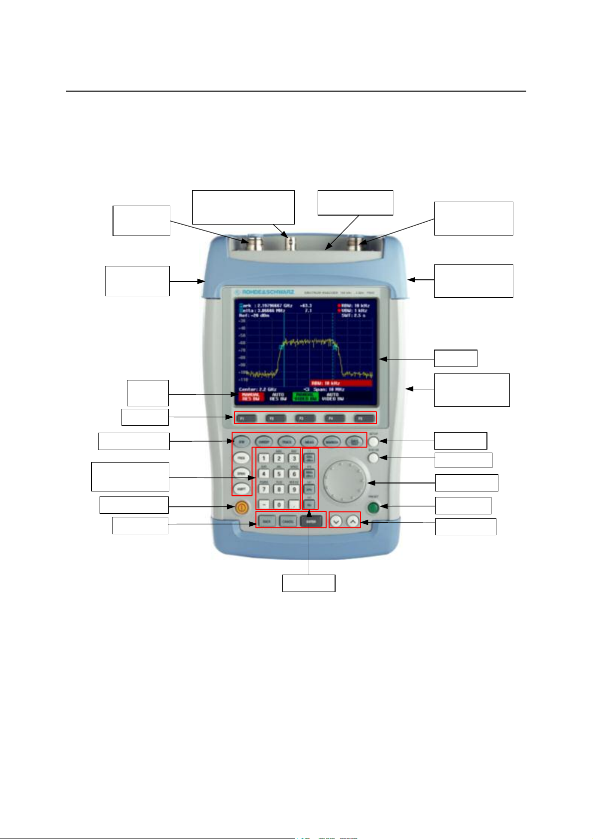
Front view
RF input
N connector
Connector for
headphones
Softkey
labels
Softkeys
Function keys
Alphanumeric
keypad
External trig. /ref. Input
CCVS/TS-ASI output
BNC connector
Control interface
Generator output
N connector
Connector for
AC power supply
Display
RS-232-C
optical interface
Setup key
Status key
Rotary knob
On/off button
Entry keys
Preset key
Cursor keys
Unit keys
2111.7040.12-04.00
1.1

Putting into Operation R&S FSH3-TV
Putting into Operation
The following section describes how to put the handheld spectrum analyzer into operation and how to
connect external devices, e.g. printers.
Section 2 describes the operation of the spectrum analyzer using simple measurements as examples.
Unpacking the Instrument
The R&S FSH3-TV comes in formfitting packaging that consists of upper and lower shells. The two
shells are held together by tape.
The packaging contains all accessories supplied.
Undo the tape to unpack the analyzer.
Upper shell
USB Cable
Power
supply
Mains plug
(country-specific)
Headphones
CD-ROM
R&S
FSH
Quick
Start
manual
Lower shell
Remove the R&S FSH3-TV and the accessories.
Remove the protective foil from the screen.
Note: Each R&S FSH3-TV comes with a unique master PIN. Keep the master PIN in a secure
place away from the R&S FSH3-TV. If someone enters an incorrect PIN three times in
succession, the R&S FSH3-TV cannot be used again until the master PIN is entered.
2111.7040.12-04.00
1.2
R&S FSH3-TV Putting into Operation
Setting up the Instrument
he handheld TV Analyzer R&S FSH3-TV has been designed for operation in labs as well as for on-site
T
use for service and maintenance applications.
For any application, the R&S FSH3-TV can be set up to optimize ease of operation and the viewing
angle of the display.
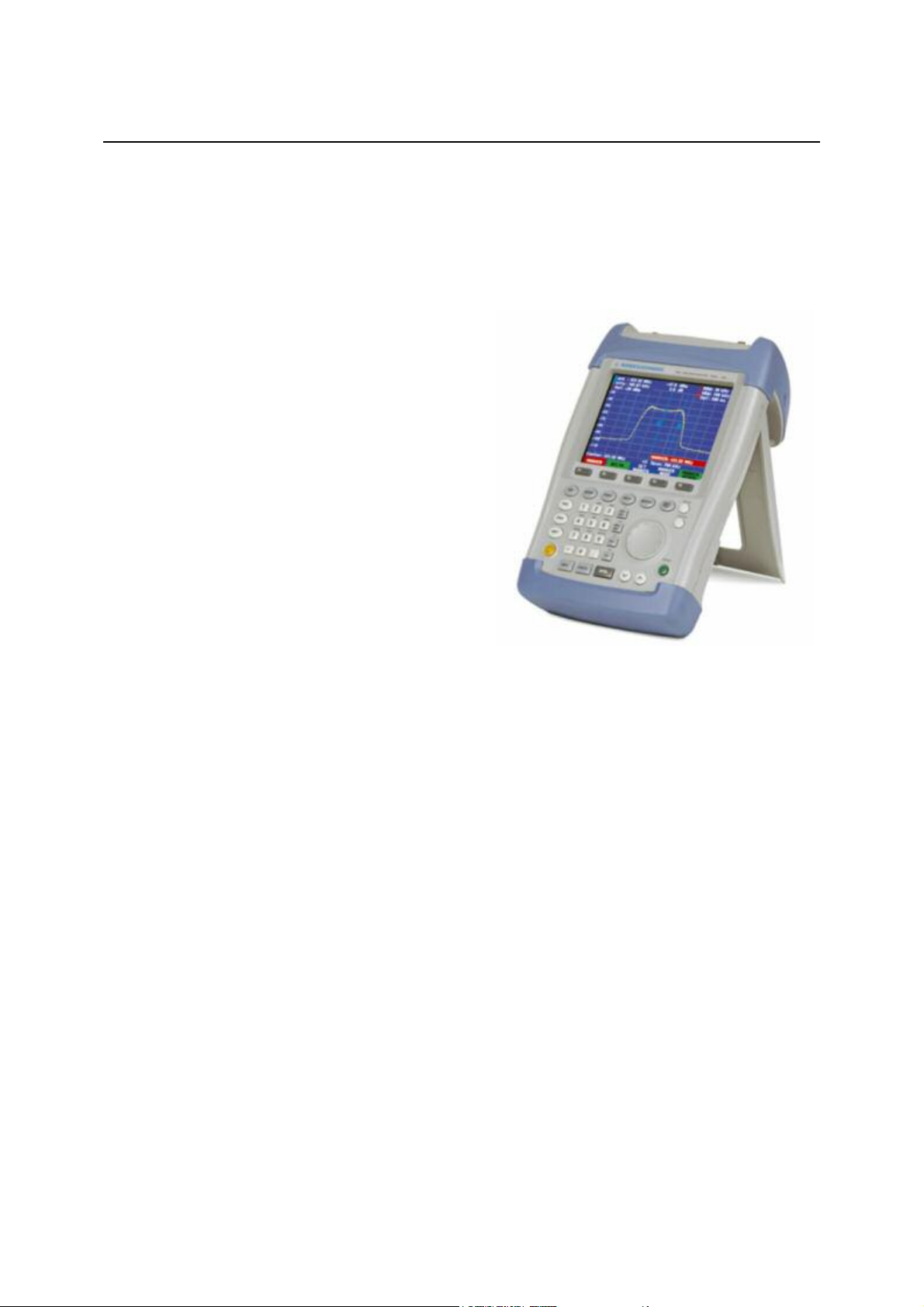
When used as a desktop instrument, the
R&S FSH3-TV can either be laid flat or it can be
propped up using the fold-out support at the back.
The R&S FSH3-TV can be laid flat for operation from
above. Because the grip is slightly raised at the back,
the R&S FSH3-TV is tilted forward to give the optimum
viewing angle for the display.
For use as a desktop, fold out the support at the rear
so that the instrument can easily be operated from the
front and the display can be read easily (see Fig.).
For on-site installation and service measurements, it is
best to hold the instrument with both hands. All the
controls are easy to reach (e.g. with your thumbs). Use
the R&S FSH-Z25 carrying bag so that you have both
hands free to adjust the DUT. The R&S FSH3-TV can
be placed in the hanger provided on the open bag for
this purpose.
To secure the instrument in place, affix its carrying handle to the front of the carrying bag with the
Velcro tape.
The carrying handle at the top of the R&S FSH3-TV can also be used to hang it from cabinet doors, for
example. The shape of the grip ensures that the instrument does not fall off.
2111.7040.12-04.00
1.3
Putting into Operation R&S FSH3-TV
Switching on the TV Analyzer
he R&S FSH3-TV can be powered using either the included power supply unit or internal battery.
T
When fully charged, the built-in nickel metal hydride battery provides an operating time of three to four
hours. On delivery, the battery in the R&S FSH3-TV may be flat. Therefore, it must be charged before
the R&S FSH3-TV can be used. If the instrument is switched off, the charging time is about four hours.
When the adapter is used, the R&S FSH3-TV’s battery is charged simultaneously. However, charging
takes much longer if the R&S FSH3-TV is switched on. A battery that is almost flat should therefore be
charged when the R&S FSH3-TV is off.
Insert the jack plug of the power supply unit into the POWER ADAPTER connector on the right-hand
side of the carrying handle so that it locks into position. Then connect the power supply unit to an AC
outlet. The voltage range of the power supply unit is 100 V to 240 V.
Caution!
In vehicles, the battery can be charged from the cigarette lighter socket using the R&S FSH-Z21 cable.
Caution!
Only the supplied power supply unit – the R&S FSH-Z33 – may be used to power the
R&S FSH3-TV or charge the battery from the AC supply.
Prior to use, make sure that the AC supply voltage is compatible with the voltage
specified on the power supply unit. Before inserting the power supply unit into the AC
power outlet, attach the appropriate adapter.
It is strictly forbidden to operate the R&S FSH3-TV via the cigarette lighter socket while
the vehicle is in motion or the engine is running. In these cases, the R&S FSH3-TV must
be off.
While the battery of the R&S FSH3-TV is being charged via the 12 V Car Adapter
R&S FSH-Z21, the car adapter must not be connected to the vehicle's ground (for
example, via the RF connector) under any circumstances.
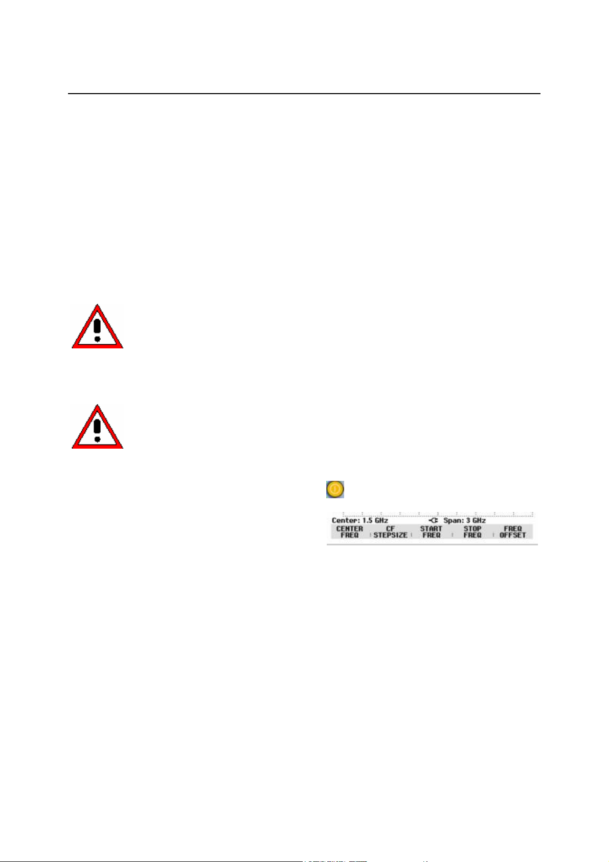
To switch on the R&S FSH3-TV, press the yellow button
To indicate that it is connected to the AC supply, the
R&S FSH3-TV displays a connector symbol in the
middle of the display above the softkey labels.
When the R&S FSH3-TV is switched on, it recalls the settings that it was using when it was last
switched off.
Note: If the internal battery is completely flat, the R&S FSH3-TV cannot be switched on even
though it is connected to the AC supply via the power supply unit. In this case, the internal
battery must be charged for a while with the instrument switched off. Only then can the
instrument be switched on.
at the bottom left of the front panel.
2111.7040.12-04.00
1.4

R&S FSH3-TV Putting into Operation
TV Analyzer Connectors
he R&S FSH3-TV has the following connectors:
T
RF input
Connect the RF input via a cable with an N connector to the DUT. Make sure that it is not overloaded.
The maximum permissible continuous power at the RF input is 20 dBm (100 mW). It can be loaded with
up to 30 dBm (1 W) for a maximum of three minutes. If the instrument is loaded with 1 W for longer, it
heats up to such an extent that it may be destroyed.
Caution!
Multifunctional BNC connector (EXT TRIG/REF CCVS/TS-ASI OUT)
The multifunctional BNC connector (EXT TRIG/REF CCVS/TS-ASI OUT) is used as an input and output
connector for a number of R&S FSH3-TV functions. The connector is controlled via the SETUP –
HARDWARE SETUP key.
• Trigger signal input
Applies an external trigger signal to start a measurement. The trigger threshold is based on the
trigger threshold of TTL signals. The input impedance is approx. 1 kB.
The RF input is AC-coupled. However, the DC input voltage must never exceed the value
specified on the housing; otherwise the coupling capacitor at the input may be destroyed
and, thus, the input attenuator or mixer as well. The RF input is protected from static
discharges and voltage pulses by a combination of limiting circuits and high-voltage
arresters.
• Video trigger input
Applies an external video signal for triggering to a TV line. The video amplitude must be in the
range from 0.5 V to 2.0 V. A composite synchronous signal can also be applied for triggering. The
input impedance is approx. 1 kB.
• 10 MHz reference input
Applies a 10 MHz signal for external frequency synchronization. The level for the reference signal
must exceed 10 dBm. The input impedance is approx. 1 kB.
• Video signal output
Output for the demodulated video signal in the analog TV receiver mode. The output is suitable for
connecting a video analyzer (e.g. the R&S VSA) or a monitor. With standard-compliant modulation,
the output signal has a video amplitude of 1 V at 75 B. The black level is connected to the DC
voltage level of 0 V. The source impedance is 75 B.
• TS-ASI output
Output for the TS-ASI signal in the digital TV receiver mode. The output is suitable for connecting
an MPEG transport stream analyzer such as the R&S DVMD, R&S DVM 400, R&S DVM 100 or
R&S DVM 50. The output amplitude is 0.8 V at 75 B. The source impedance is 75 B.
2111.7040.12-04.00
1.5

Putting into Operation R&S FSH3-TV
DC connector for external power supply (on the right-hand side of the carrying handle)
The DC connector is used to supply the R&S FSH3-TV with power from the AC/DC adapter and to
charge the R&S FSH3-TV's internal battery. The input voltage for the instrument must be between 15 V
and 20 V. Power consumption is between 7 W and 10 W, depending on the operating mode.
The battery can also be charged from a cigarette lighter socket in a vehicle. The adapter is available as
an R&S FSH3-TV accessory (R&S FSH-Z21, order no. 1145.5873.02).
Caution!
Headphones connector (on the left-hand side of the carrying handle)
A 3.5 mm jack is provided for headphones. The connector is also used as an audio measurement
output in the analog TV receiver mode.
Optical interface
(on the right-hand side of the R&S FSH3-TV; can be accessed by folding out the stand)
The optical interface is for connecting a PC via a USB connector. The Spare USB Optical Cable
R&S FSH-Z37 that comes with the R&S FSH3-TV is used to make the connection. The CD-ROM, which
is supplied with the R&S FSH3-TV, includes both the driver and the installation instruction.
While the battery of the R&S FSH3-TV is being charged via the 12 V Car Adapter
R&S FSH-Z21, the car adapter must not be connected to the vehicle's ground (for
example, via the R&S FSH3-TV's RF connector or the power sensor) under any
circumstances.
The optical connection prevents spurious measurements as a result of interference from these devices.
Use the Serial/Parallel Converter R&S FSH-Z22 for printers with a parallel interface. Use the Spare
RS-232-C Optical Cable R&S FSH-Z34 for connecting a PC or for printers with an RS-232-C interface.
Connector for preselector, VSWR bridge, power divider and power sensor (CONTROL
INTERFACE)
The connector has been especially configured for the Preselector R&S FSH-TV-Z60 and the VSWR
Bridge and Power Divider R&S FSH-Z2 as well as for Rohde & Schwarz power sensors. The connector
is used to power and control these components and to transfer data.
Tracking generator output (gen output)
Connect the tracking generator output to the DUT via an N connector. The output level can be set
between -20 dBm and 0 dBm.
Caution!
The output is AC-coupled and a voltage that does not exceed the voltage stated on the
R&S FSH3-TV housing can be fed into the output; if this voltage is exceeded, the output
may be destroyed.
2111.7040.12-04.00
1.6

R&S FSH3-TV Putting into Operation
Using the rotary knob, adjust the contrast until
Screen Settings
he R&S FSH3-TV’s screen is a transflective, passive color LCD. Indoors, its brightness depends on
T
the intensity of the backlighting. If light irradiation is strong, the ambient light supports readability. The
viewing angle can be optimized by adjusting the contrast. To achieve maximum contrast, the screen
can be switched from color display to black-and-white display.
To strike a balance between battery operating time and screen display quality, set backlighting to the
minimum brightness needed.
Setting brightness
Press the SETUP key.
Press the DISPLAY softkey.
The submenu with the contrast, lighting and color
settings opens.
Using the rotary knob or cursor keys, select LIGHT...
and confirm by pressing the DISPLAY softkey or the
ENTER key again.
The BACKLIGHT submenu for the lighting level opens.
The level can be set to HIGH, NORMAL and LOW.
Using the rotary knob or cursor keys, select the
setting you want and confirm by pressing the
DISPLAY softkey or the ENTER key.
Setting the contrast
Press the SETUP key.
Press the DISPLAY softkey.
The submenu with the contrast, lighting and color
settings opens.
Using the rotary knob or the cursor keys, select
CONTRAST... and confirm by pressing the
DISPLAY softkey or the ENTER key again.
The contrast value entry box opens.
screen legibility is optimal.
When setting the contrast, view the display at the
same angle that will be used for the application.
Confirm the entry with the ENTER key or by
pressing the DISPLAY softkey again.
The R&S FSH3-TV displays the setting in the Display
Contrast line in the overview of the setup settings.
2111.7040.12-04.00
1.7

Putting into Operation R&S FSH3-TV
Setting the screen color
Press the SETUP key.
Press the DISPLAY softkey.
The submenu with the contrast, lighting and color
settings opens.
Using the rotary knob or cursor keys, select TYPE...
and confirm with the ENTER key or by pressing the
DISPLAY softkey again.
In the submenu that opens, select COLOR or
BLACK/WHITE.
Confirm with the ENTER key or by pressing the
DISPLAY softkey again.
The R&S FSH3-TV switches to the selected color
settings.
2111.7040.12-04.00
1.8

R&S FSH3-TV Putting into Operation
Country-Specific Settings
he R&S FSH3-TV is “multilingual” and can display text in the language of your choice. The softkey
T
lettering is always in English. The default setting (factory-setting) is also English.
Selection
Press the SETUP key.
The R&S FSH3-TV displays all default settings. The last two lines indicate the current language and the
date format.
Press the LOCAL SETTINGS softkey.
A submenu with the LANGUAGE..., DATE FORMAT...
and UNIT OF LENGTH... entries opens. This menu
allows the entry of a country-specific language, date
format or the unit of length used by the R&S FSH3-TV.
Using the rotary knob or cursor keys, select the
LANGUAGE... you want from the menu and confirm
with the ENTER key or by pressing the LOCAL
SETTINGS softkey again.
The languages available are displayed in a submenu.
The selected language is highlighted in red.
Using the rotary knob or cursor keys, select the
language you want.
Using the rotary knob or cursor keys, select DATE FORMAT... from the menu and confirm with the
ENTER key or by pressing the LOCAL SETTINGS softkey again.
Using the rotary knob or cursor keys, select the date format (dd/mm/yyyy or mm/dd/yyyy) and
confirm with the ENTER key.
Using the rotary knob or cursor keys, select UNIT OF LENGTH... from the menu and confirm with the
ENTER key or by pressing the LOCAL SETTINGS softkey again.
Using the rotary knob or cursor keys, select the required unit of length (METER or FEET) and
confirm with the ENTER key.
Note: The unit of length is relevant only with distance-to-fault cable measurements in order to
display the fault distance from the measurement plane.
2111.7040.12-04.00
1.9

Putting into Operation R&S FSH3-TV
Setting the Date and Time
The R&S FSH3-TV has an internal clock that can apply a date and time stamp, e.g. for output to a
printer or stored data records. The user can reset the date and time.
Setting the date
Press the SETUP key.
Press the GENERAL softkey.
Using the rotary knob or cursor keys, select DATE...
from the menu and confirm with the ENTER key.
The value entry box above the row of softkey labels is
highlighted in red and displays the currently set date in
the selected format (dd/mm/yyyy or mm/dd/yyyy). The
active value entry field is highlighted in white.
Depending on the date format, change the day (dd)
or month (mm) by using the rotary knob, cursor keys
or a numeric entry and confirm with the ENTER key.
After the entry, the cursor automatically moves to the second field in the date (day or month, depending
on the date format). Proceed with the next two fields as with the first.
After the last data block has been entered, the R&S FSH3-TV verifies the validity of the entered date. If
the date is not valid, the R&S FSH3-TV sets the next valid date.
Setting the time
Press the SETUP key.
Press the GENERAL softkey.
Using the rotary knob or cursor keys, select TIME...
from the menu and confirm with the ENTER key.
The value entry box above the row of softkey labels is
highlighted in red and displays the currently set time in
hours:minutes format. The hours display is highlighted
in white to enter a new value.
Change the hours with the rotary knob, cursor keys
or numeric entry and confirm with the ENTER key.
After entry, the cursor automatically goes to the minutes display. The entry is the same as for the hours
display.
After the minutes have been entered, the R&S FSH3-TV verifies the validity of the entered time. If the
time is not valid, the R&S FSH3-TV sets the next valid time.
2111.7040.12-04.00
1.10

R&S FSH3-TV Charging the Battery
Charging the Battery
The R&S FSH3-TV is fitted with a nickel metal hydride battery. The operating time is three to four hours
at room temperature if the battery is fully charged.
Note: The battery in the R&S FSH3-TV is not charged when it leaves the factory. It must
therefore be charged after delivery.
When stored over an extended period, self-discharging reduces the battery charge. The battery should
therefore be charged before use if it is going to be the sole power source for a long period of operation.
The charging status of the battery is displayed by a
symbol that looks like a battery in the middle of the
screen above the row of softkey labels. If the battery is
fully charged, the entire battery symbol is white. As the
battery discharges, the white coloring disappears in
five steps until just the battery outline indicates that the
battery is flat.
The battery is charged via the included power supply unit, which is connected to the jack on the righthand side of the carrying handle.
If required, equip the power supply unit
with the country-specific plug. Remove
the plug from the power supply unit
toward the front and firmly connect the
appropriate plug to the power supply
unit.
Battery charge-level symbol
DC power jack
Power supply
AC supply plug
For rapid charging, be sure to switch off the R&S FSH3-TV during charging. The charging time is
approx. four hours.
If the R&S FSH3-TV is switched on, the charging current for the battery is reduced by the current drain
of the R&S FSH3-TV, which means the battery might not be charged.
To prevent the battery from discharging unnecessarily, the R&S FSH3-TV has an automatic cut-off or
auto power down mode that is activated if no entry is made for a definable period of time (5 minutes or
30 minutes).
The auto power down mode is deactivated in the default setting.
2111.7040.12-04.00
1.11

Selecting the Instrument Default Setup R&S FSH3-TV
The auto power down mode is set as follows:
Press the GENERAL key.
The R&S FSH3-TV opens the submenu with the
general settings. The cursor is positioned to POWER
DOWN in the menu.
Confirm the POWER DOWN selection by pressing
the ENTER key.
The R&S FSH3-TV opens a selection window with the
settings: 5 minutes, 30 minutes and DISABLE.
Using the rotary knob or cursor keys, select the
setting you want and confirm by pressing the
ENTER key or the GENERAL softkey.
Selecting the Instrument Default Setup
The PRESET key sets the R&S FSH3-TV to the default setup. This allows a new configuration based
on defined measurement parameters to be entered, without parameters from a previous setting
unintentionally still being active.
Press the PRESET key.
The R&S FSH3-TV is set to the default setup.
If certain parameters are always to deviate from the default setup for a specific application, it is also
possible to select a user-defined default setup, which is then automatically set with the PRESET key.
This is useful, for example, if the measurement is always made with a 75 matching pad. When the
PRESET key is pressed, the R&S FSH3-TV always selects 75 as the input impedance for the userspecific default setup. The user-defined default setup is generated by manually entering the desired
parameters and saving the setting as a data set. This data set can subsequently be declared the preset
settings with the aid of the R&S FSH View software.
The data set designated as the preset settings becomes the default setup of the R&S FSH3-TV as
follows:
Press the SETUP key.
Press the GENERAL softkey.
Select PRESET SETTINGS from the menu using
the cursor keys or the rotary knob.
Confirm your choice with the ENTER key or the
GENERAL softkey.
The submenu for selecting the default setup opens. Either DEFAULT or CUSTOM can be selected.
Select CUSTOM from the menu using the cursor
keys or the rotary knob.
Confirm your choice with the ENTER key or the
GENERAL softkey.
2111.7040.12-04.00
1.12

R&S FSH3-TV Multifunctional BNC Connector Control
The parameters defined in the data set for the default setup are now used as the preset settings.
f no user-specific default setup is defined, CUSTOM is inactive and cannot be selected.
I
The data set defined as the user default setup can be viewed using the R&S FSH3-TV's recall function.
Press the SAVE/PRINT key.
Press the RECALL softkey.
All stored data sets are displayed.
The status of the data set is indicated in the status
field:
P: Preset setting
: Data set disabled
Data set
overwritable
Data set not
overwritable or
deletable
User-defined
default setup
Status field
If no data sets are stored in the R&S FSH3-TV, the
message "No datasets available" is output instead of
the list of data sets.
Multifunctional BNC Connector Control
The EXT TRIG/REF CCVS/TS-ASI OUT BNC connector on the top of the R&S FSH3-TV can be used
as an input and output connector for a number of instrument functions.
• Trigger signal input
Applies an external trigger signal to start a measurement.
• Video trigger input
Applies an external video signal for triggering to a TV line.
• 10 MHz reference input
Applies a 10 MHz signal for external frequency synchronization.
• Video signal output
Output for the demodulated video signal in the analog TV receiver mode.
• TS-ASI output
Output for the TS-ASI signal in the digital TV receiver mode.
Control is via the SETUP menu.
Press the SETUP key.
Press the HARDWARE SETUP softkey.
Using the rotary knob or cursor keys, select
BNC I/O MODE... and confirm with the ENTER key
or the HARDWARE SETUP softkey.
The active setting for the multifunctional BNC
connector is highlighted in green.
Using the rotary knob or the cursor keys, select
TS-ASI OUT, CCVS OUT, EXT REF or EXT TRIG.
2111.7040.12-04.00
1.13

Controlling the RF Attenuator R&S FSH3-TV
Confirm your selection with the ENTER key or the HARDWARE SETUP softkey.
The EXT TRIG setting is only for input configuration. The use of the external trigger must be set in the
SWEEP menu (SWEEP key, TRIGGER softkey).
The TS-ASI OUT setting can only be selected in digital TV receiver mode.
The CCVS OUT setting can only be selected in analog TV receiver mode.
The input setting can be queried via the status display (press the STATUS key).
Controlling the RF Attenuator
Depending on the selected reference level, the R&S FSH3-TV sets the attenuator on the RF input to a
suitable value. It offers two modes: one for the highest possible sensitivity (LOW NOISE) and one for
the lowest possible intermodulation products (LOW DISTORTION). The difference between the two
modes is that the attenuation that the R&S FSH3-TV sets for the RF attenuator is 10 dB higher for LOW
DISTORTION than for LOW NOISE.
Press the SETUP key.
Press the HARDWARE SETUP softkey.
Using the rotary knob or cursor keys, select
DYNAMIC RANGE... from the menu.
Confirm with the ENTER key or the HARDWARE SETUP softkey.
Using the rotary knob or cursor keys, select LOW NOISE or LOW DISTORTION.
Confirm with the ENTER key or the HARDWARE SETUP softkey.
2111.7040.12-04.00
1.14

R&S FSH3-TV Using a Preamplifier
Using a Preamplifier
The R&S FSH3-TV comes with an internal preamplifier for increasing sensitivity. Depending on the
frequency, this amplifier has 15 dB to 18 dB gain and increases sensitivity by 10 to 15 dB. It is fitted
behind the RF attenuator and in front of the input mixer.
Press the SETUP key.
Press the HARDWARE SETUP softkey.
Using the rotary knob or cursor keys, select
PREAMP... .
Confirm with the ENTER key or the HARDWARE
SETUP softkey.
The R&S FSH3-TV changes to the submenu for
preamplifier configuration. The selection bar indicates
the active setting.
Using the rotary knob or cursor keys, select the
setting you want (ON or OFF) and confirm by
pressing the ENTER key.
If the preamplifier is switched on, its use is coupled to the reference level, thus ensuring the optimum
dynamic range of the R&S FSH3-TV at all times. The table below shows the positions of the RF
attenuator and the preamplifier as a function of the reference level.
Preamplifier
Ref Level
Low noise Low distortion Low noise Low distortion
–25 dBm
-24 dBm to –20 dBm 0 dB 0 dB 10 dB 10 dB On
-19 dBm to –15 dBm 0 dB 10 dB 10 dB 10 dB On
-14 dBm to –10 dBm 0 dB 10 dB 0 dB 10 dB Off
-9 dBm to 0 dBm 10 dB 20 dB 10 dB 20 dB Off
1 dBm to 10 dBm 20 dB 30 dB 20 dB 30 dB Off
11 dBm to 20 dBm 30 dB 30 dB 30 dB 30 dB Off
0 dB 0 dB 0 dB 0 dB On
OFF
RF attenuation RF attenuation Preamplifier
Preamplifier
ON
The attenuator position can be queried at any time via the status display.
2111.7040.12-04.00
1.15

PIN Entry R&S FSH3-TV
Using the rotary knob or cursor keys, select
PIN Entry
To prevent unauthorized use, the R&S FSH3-TV can be protected with a personal identification number
(PIN).
When the R&S FSH3-TV is delivered, the PIN is set to 0000 and PIN entry is disabled when the
R&S FSH3-TV is switched on. A PIN, i.e. a four-digit number, can be re-entered whenever you wish.
But it is not activated until the PIN mode has been enabled.
A new PIN is entered as follows:
Press the SETUP key to call up the SETUP menu
and the instrument settings.
Press the GENERAL softkey.
PINCODE... from the menu and press the ENTER key.
The selection box with the PIN settings is opened.
The current PIN must be entered before it can be modified. This prevents unauthorized PIN
modification.
Enter your valid PIN.
When the R&S FSH3-TV is delivered, the valid PIN is 0000.
After you enter your valid PIN, the PIN functions can be selected from the selection box. When the
R&S FSH3-TV is delivered, a new PIN can be activated only if it differs from the factory-set PIN.
Note: Before you activate the PIN mode, enter a user-defined PIN. Keep your PIN in a secure
place away from the R&S FSH3-TV. If the active PIN is not available, the instrument can
be reset to the default PIN ('0000') with the master PIN supplied with each instrument. If
the master PIN is not available, please contact an authorized Rohde & Schwarz service
center.
Entering a new PIN
Using the rotary knob or cursor keys, select New Pincode... from the menu in the selection box and
enter a new four-digit PIN. Confirm with ENTER.
The R&S FSH3-TV will prompt you to re-enter the PIN in order to prevent incorrect entries.
Re-enter the PIN.
2111.7040.12-04.00
1.16

R&S FSH3-TV PIN Entry
Activating the PIN mode
Using the rotary knob or cursor keys, select PINCODE ON from the menu and press the ENTER key.
The R&S FSH3-TV now prompts you to enter the PIN prior to its activation.
Enter the PIN and confirm with the ENTER key.
The selected PIN is now activated. The next time you switch on the R&S FSH3-TV, you must enter the
PIN before you can operate the instrument. If you enter an incorrect PIN , the R&S FSH3-TV again
prompts you for the PIN code. After three attempts with an incorrect PIN, the R&S FSH3-TV prompts
you for the master PIN.
Note: The R&S FSH3-TV comes with labels reading ‘PIN Code protected’. If the instrument is
protected with a PIN, affix one of these labels to the instrument. This warns unauthorized
users that they cannot operate the R&S FSH3-TV.
Deactivating PIN protection
Using the rotary knob or cursor keys, select PINCODE OFF from the menu and press the ENTER
key.
Prior to deactivation, the R&S FSH3-TV prompts you to enter your PIN. This prevents unauthorized
deactivation of PIN protection.
Enter your PIN number and confirm with the ENTER key.
The R&S FSH3-TV can now be operated without PIN protection.
2111.7040.12-04.00
1.17

Connecting a Printer R&S FSH3-TV
Connecting a Printer
The R&S FSH3-TV can output a screenshot to a connected printer. The Serial/Parallel Converter
R&S FSH-Z22 is available as an accessory for printers with a parallel interface. The Spare RS-232-C
Optical Cable R&S FSH-Z34 is available as an accessory for printers with an RS-232-C interface.
A printer with an RS-232-C interface can be directly connected using the RS-232-C optical interface
cable that is supplied.
Fold out the stand at the rear of the
R&S FSH3-TV.
Connect the optical connector of the
RS-232-C cable to the optical
interface on the right-hand side of the
R&S FSH3-TV.
Connect the RS-232-C connector of
the cable to the printer.
Optical RS-232-C
interface
RS-232-C cable
9-pin
connector
Connect printers with a parallel interface to the R&S FSH3-TV using the Serial/Parallel Converter
R&S FSH-Z22, thus freeing up the Centronics parallel interface to connect a printer. The R&S FSH-Z22
is powered by a 9 V alkaline battery (NEDA, IEC6LR61).
Fold out the stand at the rear of the
R&S FSH3-TV.
Connect the optical connector of the
R&S FSH-Z22 to the optical interface
on the right-hand side of the
R&S FSH3-TV.
Optical RS-232-C
interface
Connect the printer cable to the 25-
pin interface of the R&S FSH-Z22.
Switch on the serial/parallel converter
using the slide switch on its top.
R&S
FSH-Z22
Slide switch positions:
OFF The R&S FSH-Z22 is off.
ON The R&S FSH-Z22 is on, and
the Battery OK LED flashes.
AUTO OFF The R&S FSH-Z22 is on, and
the Battery OK LED flashes. If
data transmission is interrupted for more than 5 minutes,
the R&S FSH-Z22 is switched
off automatically.
2111.7040.12-04.00
1.18
R&S FSH3-TV Connecting a Printer
the rotary knob or cursor keys, select
The selection box for the available baud rates
While data is being transmitted to the printer, the "Busy" LED remains lit.
Note: The R&S FSH-Z22 is designed for a data transmission rate of max. 38 400 baud (= default
setting). Therefore, set the baud rate (PRINTER BAUD RATE) in the SETUP menu to
38 400 baud. The baud rates 9600 baud and 19 200 baud can also be set on the
R&S FSH-Z22 by opening its housing.
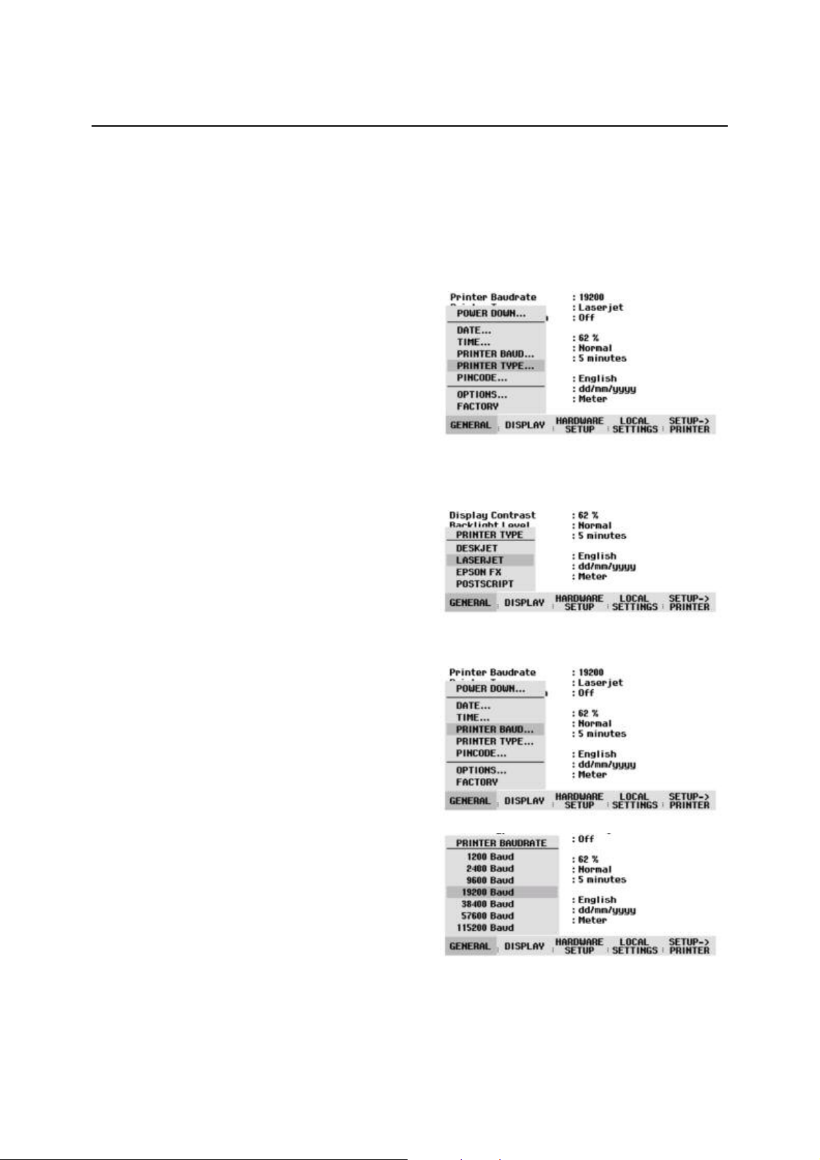
Selecting a printer
Press the SETUP key on the R&S FSH3-TV.
The R&S FSH3-TV displays the selected printer and its
baud rate in the setup settings.
To select another printer, proceed as follows:
Press the GENERAL softkey.
Using the rotary knob or cursor keys, select
PRINTER TYPE... from the menu and confirm with
the ENTER key or by pressing the GENERAL
softkey again.
Using the rotary knob or cursor keys, select the
printer you want and confirm with the ENTER key or
by pressing the GENERAL softkey again.
The R&S FSH3-TV displays the selected printer under
"Printer Type".
Next, set the baud rate for the selected printer.
Press the GENERAL softkey.
Using
PRINTER BAUD... from the menu and confirm with
the ENTER key.
(1200 baud to 115 200 baud) opens.
Using the rotary knob or cursor keys, select the
baud rate you want and confirm with the ENTER key
or by pressing the GENERAL softkey a second time.
The R&S FSH3-TV displays the selected baud rate
under "RS232 Baudrate" in the setup display.
Note: If the serial/parallel converter (R&S FSH-Z22) is used to control a printer with a parallel
The contents of the setup display can be output to the printer by pressing the SETUP -> PRINTER
softkey.
2111.7040.12-04.00
interface, set the RS-232-C interface to 38 400 baud.
1.19
Setting the Baud Rate for Remote Control R&S FSH3-TV
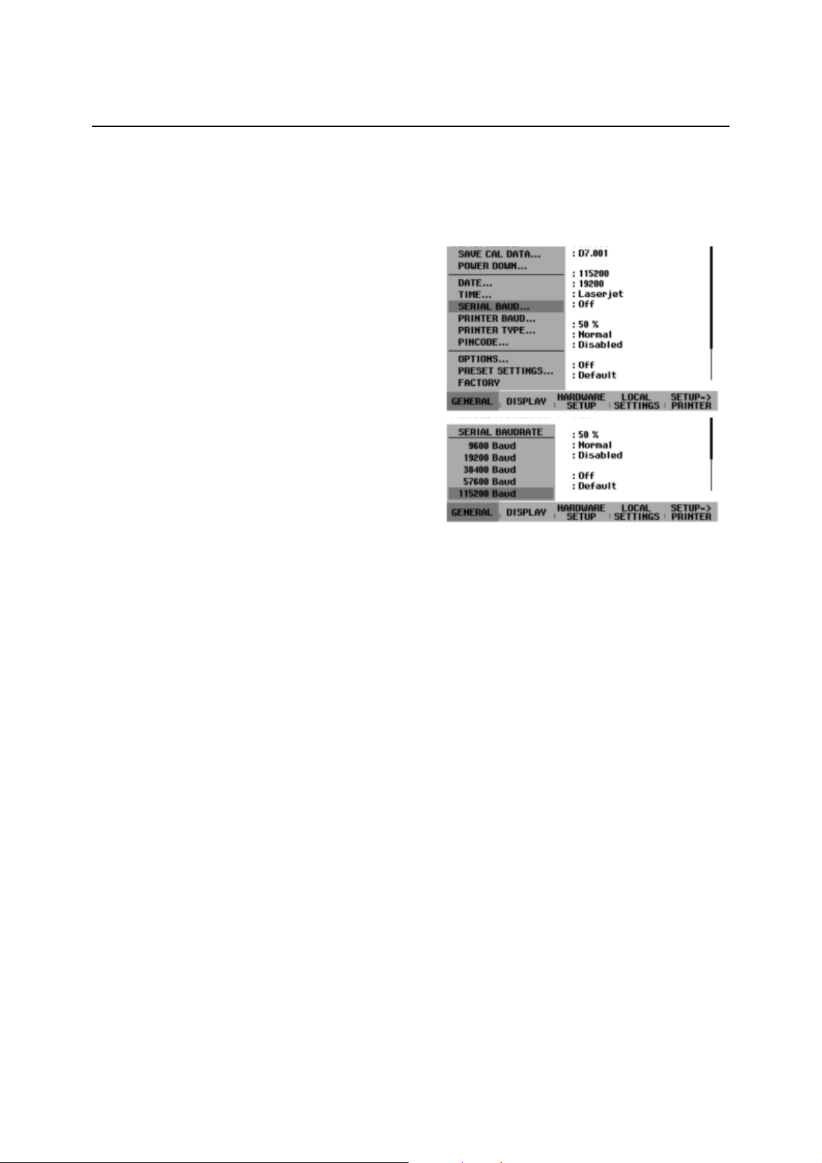
Setting the Baud Rate for Remote Control
The R&S FSH3-TV offers different baud rates for remote control. The desired baud rate is set via the
SETUP menu.
Press the SETUP key.
Press the GENERAL softkey.
Use the rotary knob or the cursor keys to select
SERIAL BAUD... from the menu and confirm the
selection with the ENTER key.
The selection box for the available baud rates
(9600 baud to 115200 baud) opens.
Use the rotary knob or the cursor keys to select the
baud rate you want and confirm the entry with the
ENTER key or by pressing the GENERAL softkey
again.
The R&S FSH3-TV displays the selected baud rate
under SERIAL BAUDRATE in the setup display.
Enabling Options
The R&S FSH3-TV can be fitted with options (e.g. distance-to-fault measurements on cables) which are
enabled by entering a key code. The key code is based on the unique serial number of the instrument.
To add an option, enable it with a key code.
Operation
Press the SETUP key.
Press the GENERAL key.
Using the rotary knob or cursor keys, select OPTIONS... from the menu and confirm with the ENTER
key.
Enter the key code (ten-digit number) for the option with the numeric keys and confirm with the ENTER
key.
If the correct key code is entered, the R&S FSH3-TV displays "<....> Option enabled".
If an invalid key code is entered, the R&S FSH3-TV displays "Option key error".
The correct key code can then be entered.
2111.7040.12-04.00
1.20
R&S FSH3-TV Checking the Installed Options
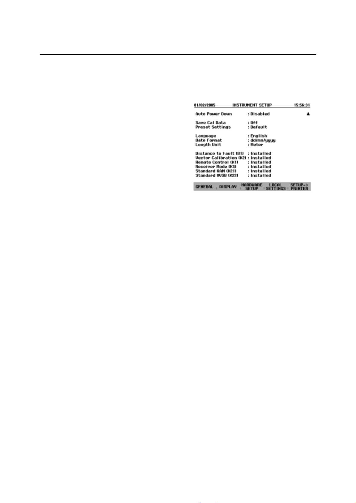
Checking the Installed Options
The R&S FSH3-TV displays the installed options in the SETUP menu so you can check them:
Press the SETUP key.
Using the rotary knob or the cursor keys, scroll the
status display downwards.
The R&S FSH3-TV displays all available options
together with their current status.
2111.7040.12-04.00
1.21
 Loading...