

Page 1
®
R&S
FPS
Signal and Spectrum
Analyzer
Getting Started
(=CQÌ2)
1319.3362.02 ─ 07
Getting Started
Test & Measurement
Page 2

This manual applies to the following R&S®FPS models with firmware version 1.40
and higher:
●
R&S®FPS4 (1319.2008K04)
●
R&S®FPS7 (1319.2008K07)
●
R&S®FPS13 (1319.2008K13)
●
R&S®FPS30 (1319.2008K30)
●
R&S®FPS40 (1319.2008K40)
In addition to the base unit, the following options are described:
●
R&S FPS-B4, OCXO (1321.4291.02)
●
R&S FPS-B10, external generator control (1321.4256.02)
●
R&S FPS-B22, preamplifier (1321.4027.02)
●
R&S FPS-B25, electronic attenuator (1321.4033.02)
●
R&S FPS-B40 bandwidth extension (1321.4040.02)
●
R&S FPS-B160 bandwidth extension (1321.4285.xx)
The software contained in this product makes use of several valuable open source software packages.
For information, see the "Open Source Acknowledgment" on the user documentation CD-ROM (included
in delivery).
Rohde & Schwarz would like to thank the open source community for their valuable contribution to embedded computing.
© 2016 Rohde & Schwarz GmbH & Co. KG
Mühldorfstr. 15, 81671 München, Germany
Phone: +49 89 41 29 - 0
Fax: +49 89 41 29 12 164
Email: info@rohde-schwarz.com
Internet: www.rohde-schwarz.com
Subject to change – Data without tolerance limits is not binding.
R&S® is a registered trademark of Rohde & Schwarz GmbH & Co. KG.
Trade names are trademarks of the owners.
The following abbreviations are used throughout this manual: R&S®FPS is abbreviated as R&S FPS.
R&S®MultiView is abbreviated as MultiView.
Page 3

Basic Safety Instructions
All plants and locations of the Rohde & Schwarz group of companies make every
effort to keep the safety standards of our products up to date and to offer our
customers the highest possible degree of safety. Our products and the auxiliary
equipment they require are designed, built and tested in accordance with the
safety standards that apply in each case. Compliance with these standards is
continuously monitored by our quality assurance system. The product described
here has been designed, built and tested in accordance with the EC Certificate of
Conformity and has left the manufacturer’s plant in a condition fully complying
with safety standards. To maintain this condition and to ensure safe operation,
you must observe all instructions and warnings provided in this manual. If you
have any questions regarding these safety instructions, the Rohde & Schwarz
group of companies will be happy to answer them.
Furthermore, it is your responsibility to use the product in an appropriate manner.
This product is designed for use solely in industrial and laboratory environments
or, if expressly permitted, also in the field and must not be used in any way that
may cause personal injury or property damage. You are responsible if the product
is used for any purpose other than its designated purpose or in disregard of the
manufacturer's instructions. The manufacturer shall assume no responsibility for
such use of the product.
The product is used for its designated purpose if it is used in accordance with its
product documentation and within its performance limits (see data sheet,
documentation, the following safety instructions). Using the product requires
technical skills and, in some cases, a basic knowledge of English. It is therefore
essential that only skilled and specialized staff or thoroughly trained personnel
with the required skills be allowed to use the product. If personal safety gear is
required for using Rohde & Schwarz products, this will be indicated at the
appropriate place in the product documentation. Keep the basic safety
instructions and the product documentation in a safe place and pass them on to
the subsequent users.
1171.0000.52 - 08 Page 1
Page 4

Basic Safety Instructions
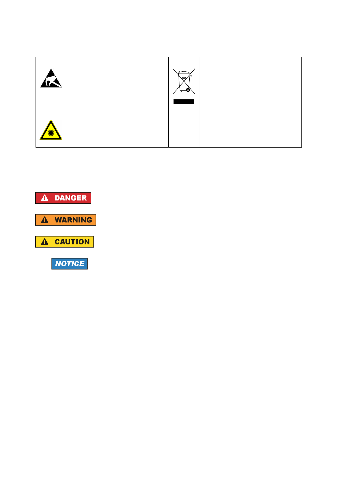
Symbol
Meaning
Symbol
Meaning
Notice, general danger location
Observe product documentation
ON/OFF Power
Caution when handling heavy
equipment
Standby indication
Danger of electric shock
Direct current (DC)
Caution ! Hot surface
Alternating current (AC)
Protective conductor terminal
To identify any terminal which is
intended for connection to an
external conductor for protection
against electric shock in case of a
fault, or the terminal of a
protective earth
Direct/alternating current (DC/AC)
Earth (Ground)
Class II Equipment
to identify equipment meeting the
safety requirements specified for
Class II equipment
(device protected by double or
reinforced insulation)
Frame or chassis Ground terminal
EU labeling for batteries and
accumulators. For additional
information, see section "Waste
disposal/Environmental
protection", item 1.
Observing the safety instructions will help prevent personal injury or damage of
any kind caused by dangerous situations. Therefore, carefully read through and
adhere to the following safety instructions before and when using the product. It is
also absolutely essential to observe the additional safety instructions on personal
safety, for example, that appear in relevant parts of the product documentation. In
these safety instructions, the word "product" refers to all merchandise sold and
distributed by the Rohde & Schwarz group of companies, including instruments,
systems and all accessories. For product-specific information, see the data sheet
and the product documentation.
Safety labels on products
The following safety labels are used on products to warn against risks and
dangers.
1171.0000.52 - 08 Page 2
Page 5
Basic Safety Instructions
Symbol
Meaning
Symbol
Meaning
Be careful when handling
electrostatic sensitive devices
EU labeling for separate collection
of electrical and electronic devices
For additional information, see
section "Waste
disposal/Environmental
protection", item 2.
Warning! Laser radiation
For additional information, see
section "Operation", item 7.
Indicates a hazardous situation which, if not avoided, will
result in death or serious injury.
Indicates a hazardous situation which, if not avoided, could
result in death or serious injury.
Indicates a hazardous situation which, if not avoided, could
result in minor or moderate injury.
Indicates information considered important, but not hazardrelated, e.g. messages relating to property damage.
In the product documentation, the word ATTENTION is
used synonymously.
Signal words and their meaning
The following signal words are used in the product documentation in order to
warn the reader about risks and dangers.
These signal words are in accordance with the standard definition for civil
applications in the European Economic Area. Definitions that deviate from the
standard definition may also exist in other economic areas or military applications.
It is therefore essential to make sure that the signal words described here are
always used only in connection with the related product documentation and the
related product. The use of signal words in connection with unrelated products or
documentation can result in misinterpretation and in personal injury or material
damage.
1171.0000.52 - 08 Page 3
Page 6

Basic Safety Instructions
Operating states and operating positions
The product may be operated only under the operating conditions and in the
positions specified by the manufacturer, without the product's ventilation being
obstructed. If the manufacturer's specifications are not observed, this can result in
electric shock, fire and/or serious personal injury or death. Applicable local or
national safety regulations and rules for the prevention of accidents must be
observed in all work performed.
1. Unless otherwise specified, the following requirements apply to Rohde &
Schwarz products:
predefined operating position is always with the housing floor facing down, IP
protection 2X, use only indoors, max. operating altitude 2000 m above sea
level, max. transport altitude 4500 m above sea level. A tolerance of ±10 %
shall apply to the nominal voltage and ±5 % to the nominal frequency,
overvoltage category 2, pollution degree 2.
2. Do not place the product on surfaces, vehicles, cabinets or tables that for
reasons of weight or stability are unsuitable for this purpose. Always follow the
manufacturer's installation instructions when installing the product and
fastening it to objects or structures (e.g. walls and shelves). An installation that
is not carried out as described in the product documentation could result in
personal injury or even death.
3. Do not place the product on heat-generating devices such as radiators or fan
heaters. The ambient temperature must not exceed the maximum temperature
specified in the product documentation or in the data sheet. Product
overheating can cause electric shock, fire and/or serious personal injury or
even death.
Electrical safety
If the information on electrical safety is not observed either at all or to the extent
necessary, electric shock, fire and/or serious personal injury or death may occur.
1. Prior to switching on the product, always ensure that the nominal voltage
setting on the product matches the nominal voltage of the mains-supply
network. If a different voltage is to be set, the power fuse of the product may
have to be changed accordingly.
2. In the case of products of safety class I with movable power cord and
connector, operation is permitted only on sockets with a protective conductor
contact and protective conductor.
1171.0000.52 - 08 Page 4
Page 7

Basic Safety Instructions
3. Intentionally breaking the protective conductor either in the feed line or in the
product itself is not permitted. Doing so can result in the danger of an electric
shock from the product. If extension cords or connector strips are
implemented, they must be checked on a regular basis to ensure that they are
safe to use.
4. If there is no power switch for disconnecting the product from the mains, or if
the power switch is not suitable for this purpose, use the plug of the
connecting cable to disconnect the product from the mains. In such cases,
always ensure that the power plug is easily reachable and accessible at all
times. For example, if the power plug is the disconnecting device, the length of
the connecting cable must not exceed 3 m. Functional or electronic switches
are not suitable for providing disconnection from the AC supply network. If
products without power switches are integrated into racks or systems, the
disconnecting device must be provided at the system level.
5. Never use the product if the power cable is damaged. Check the power cables
on a regular basis to ensure that they are in proper operating condition. By
taking appropriate safety measures and carefully laying the power cable,
ensure that the cable cannot be damaged and that no one can be hurt by, for
example, tripping over the cable or suffering an electric shock.
6. The product may be operated only from TN/TT supply networks fuse-protected
with max. 16 A (higher fuse only after consulting with the Rohde & Schwarz
group of companies).
7. Do not insert the plug into sockets that are dusty or dirty. Insert the plug firmly
and all the way into the socket provided for this purpose. Otherwise, sparks
that result in fire and/or injuries may occur.
8. Do not overload any sockets, extension cords or connector strips; doing so
can cause fire or electric shocks.
9. For measurements in circuits with voltages Vrms > 30 V, suitable measures
(e.g. appropriate measuring equipment, fuse protection, current limiting,
electrical separation, insulation) should be taken to avoid any hazards.
10. Ensure that the connections with information technology equipment, e.g. PCs
or other industrial computers, comply with the IEC 60950-1 / EN 60950-1 or
IEC 61010-1 / EN 61010-1 standards that apply in each case.
11. Unless expressly permitted, never remove the cover or any part of the housing
while the product is in operation. Doing so will expose circuits and
components and can lead to injuries, fire or damage to the product.
1171.0000.52 - 08 Page 5
Page 8

Basic Safety Instructions
12. If a product is to be permanently installed, the connection between the
protective conductor terminal on site and the product's protective conductor
must be made first before any other connection is made. The product may be
installed and connected only by a licensed electrician.
13. For permanently installed equipment without built-in fuses, circuit breakers or
similar protective devices, the supply circuit must be fuse-protected in such a
way that anyone who has access to the product, as well as the product itself,
is adequately protected from injury or damage.
14. Use suitable overvoltage protection to ensure that no overvoltage (such as
that caused by a bolt of lightning) can reach the product. Otherwise, the
person operating the product will be exposed to the danger of an electric
shock.
15. Any object that is not designed to be placed in the openings of the housing
must not be used for this purpose. Doing so can cause short circuits inside the
product and/or electric shocks, fire or injuries.
16. Unless specified otherwise, products are not liquid-proof (see also section
"Operating states and operating positions", item 1). Therefore, the equipment
must be protected against penetration by liquids. If the necessary precautions
are not taken, the user may suffer electric shock or the product itself may be
damaged, which can also lead to personal injury.
17. Never use the product under conditions in which condensation has formed or
can form in or on the product, e.g. if the product has been moved from a cold
to a warm environment. Penetration by water increases the risk of electric
shock.
18. Prior to cleaning the product, disconnect it completely from the power supply
(e.g. AC supply network or battery). Use a soft, non-linting cloth to clean the
product. Never use chemical cleaning agents such as alcohol, acetone or
diluents for cellulose lacquers.
Operation
1. Operating the products requires special training and intense concentration.
Make sure that persons who use the products are physically, mentally and
emotionally fit enough to do so; otherwise, injuries or material damage may
occur. It is the responsibility of the employer/operator to select suitable
personnel for operating the products.
2. Before you move or transport the product, read and observe the section titled
"Transport".
1171.0000.52 - 08 Page 6
Page 9

Basic Safety Instructions
3. As with all industrially manufactured goods, the use of substances that induce
an allergic reaction (allergens) such as nickel cannot be generally excluded. If
you develop an allergic reaction (such as a skin rash, frequent sneezing, red
eyes or respiratory difficulties) when using a Rohde & Schwarz product,
consult a physician immediately to determine the cause and to prevent health
problems or stress.
4. Before you start processing the product mechanically and/or thermally, or
before you take it apart, be sure to read and pay special attention to the
section titled "Waste disposal/Environmental protection", item 1.
5. Depending on the function, certain products such as RF radio equipment can
produce an elevated level of electromagnetic radiation. Considering that
unborn babies require increased protection, pregnant women must be
protected by appropriate measures. Persons with pacemakers may also be
exposed to risks from electromagnetic radiation. The employer/operator must
evaluate workplaces where there is a special risk of exposure to radiation and,
if necessary, take measures to avert the potential danger.
6. Should a fire occur, the product may release hazardous substances (gases,
fluids, etc.) that can cause health problems. Therefore, suitable measures
must be taken, e.g. protective masks and protective clothing must be worn.
7. Laser products are given warning labels that are standardized according to
their laser class. Lasers can cause biological harm due to the properties of
their radiation and due to their extremely concentrated electromagnetic power.
If a laser product (e.g. a CD/DVD drive) is integrated into a Rohde & Schwarz
product, absolutely no other settings or functions may be used as described in
the product documentation. The objective is to prevent personal injury (e.g.
due to laser beams).
8. EMC classes (in line with EN 55011/CISPR 11, and analogously with EN
55022/CISPR 22, EN 55032/CISPR 32)
Class A equipment:
Equipment suitable for use in all environments except residential
environments and environments that are directly connected to a lowvoltage supply network that supplies residential buildings
Note: Class A equipment is intended for use in an industrial environment.
This equipment may cause radio disturbances in residential environments,
due to possible conducted as well as radiated disturbances. In this case,
the operator may be required to take appropriate measures to eliminate
these disturbances.
1171.0000.52 - 08 Page 7
Page 10

Basic Safety Instructions
Class B equipment:
Equipment suitable for use in residential environments and environments
that are directly connected to a low-voltage supply network that supplies
residential buildings
Repair and service
1. The product may be opened only by authorized, specially trained personnel.
Before any work is performed on the product or before the product is opened,
it must be disconnected from the AC supply network. Otherwise, personnel will
be exposed to the risk of an electric shock.
2. Adjustments, replacement of parts, maintenance and repair may be performed
only by electrical experts authorized by Rohde & Schwarz. Only original parts
may be used for replacing parts relevant to safety (e.g. power switches, power
transformers, fuses). A safety test must always be performed after parts
relevant to safety have been replaced (visual inspection, protective conductor
test, insulation resistance measurement, leakage current measurement,
functional test). This helps ensure the continued safety of the product.
Batteries and rechargeable batteries/cells
If the information regarding batteries and rechargeable batteries/cells is not
observed either at all or to the extent necessary, product users may be exposed
to the risk of explosions, fire and/or serious personal injury, and, in some cases,
death. Batteries and rechargeable batteries with alkaline electrolytes (e.g. lithium
cells) must be handled in accordance with the EN 62133 standard.
1. Cells must not be taken apart or crushed.
2. Cells or batteries must not be exposed to heat or fire. Storage in direct sunlight
must be avoided. Keep cells and batteries clean and dry. Clean soiled
connectors using a dry, clean cloth.
3. Cells or batteries must not be short-circuited. Cells or batteries must not be
stored in a box or in a drawer where they can short-circuit each other, or
where they can be short-circuited by other conductive materials. Cells and
batteries must not be removed from their original packaging until they are
ready to be used.
4. Cells and batteries must not be exposed to any mechanical shocks that are
stronger than permitted.
5. If a cell develops a leak, the fluid must not be allowed to come into contact
with the skin or eyes. If contact occurs, wash the affected area with plenty of
water and seek medical aid.
1171.0000.52 - 08 Page 8
Page 11

Basic Safety Instructions
6. Improperly replacing or charging cells or batteries that contain alkaline
electrolytes (e.g. lithium cells) can cause explosions. Replace cells or batteries
only with the matching Rohde & Schwarz type (see parts list) in order to
ensure the safety of the product.
7. Cells and batteries must be recycled and kept separate from residual waste.
Rechargeable batteries and normal batteries that contain lead, mercury or
cadmium are hazardous waste. Observe the national regulations regarding
waste disposal and recycling.
Transport
1. The product may be very heavy. Therefore, the product must be handled with
care. In some cases, the user may require a suitable means of lifting or
moving the product (e.g. with a lift-truck) to avoid back or other physical
injuries.
2. Handles on the products are designed exclusively to enable personnel to
transport the product. It is therefore not permissible to use handles to fasten
the product to or on transport equipment such as cranes, fork lifts, wagons,
etc. The user is responsible for securely fastening the products to or on the
means of transport or lifting. Observe the safety regulations of the
manufacturer of the means of transport or lifting. Noncompliance can result in
personal injury or material damage.
3. If you use the product in a vehicle, it is the sole responsibility of the driver to
drive the vehicle safely and properly. The manufacturer assumes no
responsibility for accidents or collisions. Never use the product in a moving
vehicle if doing so could distract the driver of the vehicle. Adequately secure
the product in the vehicle to prevent injuries or other damage in the event of
an accident.
Waste disposal/Environmental protection
1. Specially marked equipment has a battery or accumulator that must not be
disposed of with unsorted municipal waste, but must be collected separately. It
may only be disposed of at a suitable collection point or via a
Rohde & Schwarz customer service center.
2. Waste electrical and electronic equipment must not be disposed of with
unsorted municipal waste, but must be collected separately.
Rohde & Schwarz GmbH & Co. KG has developed a disposal concept and
takes full responsibility for take-back obligations and disposal obligations for
manufacturers within the EU. Contact your Rohde & Schwarz customer
service center for environmentally responsible disposal of the product.
1171.0000.52 - 08 Page 9
Page 12

Instrucciones de seguridad elementales
3. If products or their components are mechanically and/or thermally processed
in a manner that goes beyond their intended use, hazardous substances
(heavy-metal dust such as lead, beryllium, nickel) may be released. For this
reason, the product may only be disassembled by specially trained personnel.
Improper disassembly may be hazardous to your health. National waste
disposal regulations must be observed.
4. If handling the product releases hazardous substances or fuels that must be
disposed of in a special way, e.g. coolants or engine oils that must be
replenished regularly, the safety instructions of the manufacturer of the
hazardous substances or fuels and the applicable regional waste disposal
regulations must be observed. Also observe the relevant safety instructions in
the product documentation. The improper disposal of hazardous substances
or fuels can cause health problems and lead to environmental damage.
For additional information about environmental protection, visit the
Rohde & Schwarz website.
Instrucciones de seguridad elementales
¡Es imprescindible leer y cumplir las siguientes instrucciones e
informaciones de seguridad!
El principio del grupo de empresas Rohde & Schwarz consiste en tener nuestros
productos siempre al día con los estándares de seguridad y de ofrecer a nuestros
clientes el máximo grado de seguridad. Nuestros productos y todos los equipos
adicionales son siempre fabricados y examinados según las normas de
seguridad vigentes. Nuestro sistema de garantía de calidad controla
constantemente que sean cumplidas estas normas. El presente producto ha sido
fabricado y examinado según el certificado de conformidad de la UE y ha salido
de nuestra planta en estado impecable según los estándares técnicos de
seguridad. Para poder preservar este estado y garantizar un funcionamiento libre
de peligros, el usuario deberá atenerse a todas las indicaciones, informaciones
de seguridad y notas de alerta. El grupo de empresas Rohde & Schwarz está
siempre a su disposición en caso de que tengan preguntas referentes a estas
informaciones de seguridad.
1171.0000.52 - 08 Page 10
Page 13

Instrucciones de seguridad elementales
Además queda en la responsabilidad del usuario utilizar el producto en la forma
debida. Este producto está destinado exclusivamente al uso en la industria y el
laboratorio o, si ha sido expresamente autorizado, para aplicaciones de campo y
de ninguna manera deberá ser utilizado de modo que alguna persona/cosa
pueda sufrir daño. El uso del producto fuera de sus fines definidos o sin tener en
cuenta las instrucciones del fabricante queda en la responsabilidad del usuario.
El fabricante no se hace en ninguna forma responsable de consecuencias a
causa del mal uso del producto.
Se parte del uso correcto del producto para los fines definidos si el producto es
utilizado conforme a las indicaciones de la correspondiente documentación del
producto y dentro del margen de rendimiento definido (ver hoja de datos,
documentación, informaciones de seguridad que siguen). El uso del producto
hace necesarios conocimientos técnicos y ciertos conocimientos del idioma
inglés. Por eso se debe tener en cuenta que el producto solo pueda ser operado
por personal especializado o personas instruidas en profundidad con las
capacidades correspondientes. Si fuera necesaria indumentaria de seguridad
para el uso de productos de Rohde & Schwarz, encontraría la información debida
en la documentación del producto en el capítulo correspondiente. Guarde bien
las informaciones de seguridad elementales, así como la documentación del
producto, y entréguelas a usuarios posteriores.
Tener en cuenta las informaciones de seguridad sirve para evitar en lo posible
lesiones o daños por peligros de toda clase. Por eso es imprescindible leer
detalladamente y comprender por completo las siguientes informaciones de
seguridad antes de usar el producto, y respetarlas durante el uso del producto.
Deberán tenerse en cuenta todas las demás informaciones de seguridad, como
p. ej. las referentes a la protección de personas, que encontrarán en el capítulo
correspondiente de la documentación del producto y que también son de
obligado cumplimiento. En las presentes informaciones de seguridad se recogen
todos los objetos que distribuye el grupo de empresas Rohde & Schwarz bajo la
denominación de "producto", entre ellos también aparatos, instalaciones así
como toda clase de accesorios. Los datos específicos del producto figuran en la
hoja de datos y en la documentación del producto.
1171.0000.52 - 08 Page 11
Page 14
Instrucciones de seguridad elementales
Símbolo
Significado
Símbolo
Significado
Aviso: punto de peligro general
Observar la documentación del
producto
Tensión de alimentación de
PUESTA EN MARCHA / PARADA
Atención en el manejo de
dispositivos de peso elevado
Indicación de estado de espera
(standby)
Peligro de choque eléctrico
Corriente continua (DC)
Advertencia: superficie caliente
Corriente alterna (AC)
Conexión a conductor de
protección
Corriente continua / Corriente
alterna (DC/AC)
Conexión a tierra
El aparato está protegido en su
totalidad por un aislamiento doble
(reforzado)
Conexión a masa
Distintivo de la UE para baterías y
acumuladores
Más información en la sección
"Eliminación/protección del medio
ambiente", punto 1.
Aviso: Cuidado en el manejo de
dispositivos sensibles a la
electrostática (ESD)
Distintivo de la UE para la
eliminación por separado de
dispositivos eléctricos y
electrónicos
Más información en la sección
"Eliminación/protección del medio
ambiente", punto 2.
Advertencia: rayo láser
Más información en la sección
"Funcionamiento", punto 7.
Señalización de seguridad de los productos
Las siguientes señales de seguridad se utilizan en los productos para advertir
sobre riesgos y peligros.
1171.0000.52 - 08 Page 12
Page 15
Instrucciones de seguridad elementales
Indica una situación de peligro que, si no se evita,
causa lesiones graves o incluso la muerte.
Indica una situación de peligro que, si no se evita,
puede causar lesiones graves o incluso la muerte.
Indica una situación de peligro que, si no se evita,
puede causar lesiones leves o moderadas.
Indica información que se considera importante, pero
no en relación con situaciones de peligro; p. ej., avisos
sobre posibles daños materiales.
En la documentación del producto se emplea de forma
sinónima el término CUIDADO.
Palabras de señal y su significado
En la documentación del producto se utilizan las siguientes palabras de señal
con el fin de advertir contra riesgos y peligros.
Las palabras de señal corresponden a la definición habitual para aplicaciones
civiles en el área económica europea. Pueden existir definiciones diferentes a
esta definición en otras áreas económicas o en aplicaciones militares. Por eso se
deberá tener en cuenta que las palabras de señal aquí descritas sean utilizadas
siempre solamente en combinación con la correspondiente documentación del
producto y solamente en combinación con el producto correspondiente. La
utilización de las palabras de señal en combinación con productos o
documentaciones que no les correspondan puede llevar a interpretaciones
equivocadas y tener por consecuencia daños en personas u objetos.
1171.0000.52 - 08 Page 13
Page 16

Instrucciones de seguridad elementales
Estados operativos y posiciones de funcionamiento
El producto solamente debe ser utilizado según lo indicado por el fabricante
respecto a los estados operativos y posiciones de funcionamiento sin que se
obstruya la ventilación. Si no se siguen las indicaciones del fabricante, pueden
producirse choques eléctricos, incendios y/o lesiones graves con posible
consecuencia de muerte. En todos los trabajos deberán ser tenidas en cuenta las
normas nacionales y locales de seguridad del trabajo y de prevención de
accidentes.
1. Si no se convino de otra manera, es para los productos Rohde & Schwarz
válido lo que sigue:
como posición de funcionamiento se define por principio la posición con el
suelo de la caja para abajo, modo de protección IP 2X, uso solamente en
estancias interiores, utilización hasta 2000 m sobre el nivel del mar, transporte
hasta 4500 m sobre el nivel del mar. Se aplicará una tolerancia de ±10 %
sobre el voltaje nominal y de ±5 % sobre la frecuencia nominal. Categoría de
sobrecarga eléctrica 2, índice de suciedad 2.
2. No sitúe el producto encima de superficies, vehículos, estantes o mesas, que
por sus características de peso o de estabilidad no sean aptos para él. Siga
siempre las instrucciones de instalación del fabricante cuando instale y
asegure el producto en objetos o estructuras (p. ej. paredes y estantes). Si se
realiza la instalación de modo distinto al indicado en la documentación del
producto, se pueden causar lesiones o, en determinadas circunstancias,
incluso la muerte.
3. No ponga el producto sobre aparatos que generen calor (p. ej. radiadores o
calefactores). La temperatura ambiente no debe superar la temperatura
máxima especificada en la documentación del producto o en la hoja de datos.
En caso de sobrecalentamiento del producto, pueden producirse choques
eléctricos, incendios y/o lesiones graves con posible consecuencia de muerte.
Seguridad eléctrica
Si no se siguen (o se siguen de modo insuficiente) las indicaciones del fabricante
en cuanto a seguridad eléctrica, pueden producirse choques eléctricos, incendios
y/o lesiones graves con posible consecuencia de muerte.
1. Antes de la puesta en marcha del producto se deberá comprobar siempre que
la tensión preseleccionada en el producto coincida con la de la red de
alimentación eléctrica. Si es necesario modificar el ajuste de tensión, también
se deberán cambiar en caso dado los fusibles correspondientes del producto.
1171.0000.52 - 08 Page 14
Page 17

Instrucciones de seguridad elementales
2. Los productos de la clase de protección I con alimentación móvil y enchufe
individual solamente podrán enchufarse a tomas de corriente con contacto de
seguridad y con conductor de protección conectado.
3. Queda prohibida la interrupción intencionada del conductor de protección,
tanto en la toma de corriente como en el mismo producto. La interrupción
puede tener como consecuencia el riesgo de que el producto sea fuente de
choques eléctricos. Si se utilizan cables alargadores o regletas de enchufe,
deberá garantizarse la realización de un examen regular de los mismos en
cuanto a su estado técnico de seguridad.
4. Si el producto no está equipado con un interruptor para desconectarlo de la
red, o bien si el interruptor existente no resulta apropiado para la desconexión
de la red, el enchufe del cable de conexión se deberá considerar como un
dispositivo de desconexión.
El dispositivo de desconexión se debe poder alcanzar fácilmente y debe estar
siempre bien accesible. Si, p. ej., el enchufe de conexión a la red es el
dispositivo de desconexión, la longitud del cable de conexión no debe superar
3 m).
Los interruptores selectores o electrónicos no son aptos para el corte de la red
eléctrica. Si se integran productos sin interruptor en bastidores o
instalaciones, se deberá colocar el interruptor en el nivel de la instalación.
5. No utilice nunca el producto si está dañado el cable de conexión a red.
Compruebe regularmente el correcto estado de los cables de conexión a red.
Asegúrese, mediante las medidas de protección y de instalación adecuadas,
de que el cable de conexión a red no pueda ser dañado o de que nadie pueda
ser dañado por él, p. ej. al tropezar o por un choque eléctrico.
6. Solamente está permitido el funcionamiento en redes de alimentación TN/TT
aseguradas con fusibles de 16 A como máximo (utilización de fusibles de
mayor amperaje solo previa consulta con el grupo de empresas Rohde &
Schwarz).
7. Nunca conecte el enchufe en tomas de corriente sucias o llenas de polvo.
Introduzca el enchufe por completo y fuertemente en la toma de corriente. La
no observación de estas medidas puede provocar chispas, fuego y/o lesiones.
8. No sobrecargue las tomas de corriente, los cables alargadores o las regletas
de enchufe ya que esto podría causar fuego o choques eléctricos.
9. En las mediciones en circuitos de corriente con una tensión Ueff > 30 V se
deberán tomar las medidas apropiadas para impedir cualquier peligro (p. ej.
medios de medición adecuados, seguros, limitación de tensión, corte
protector, aislamiento etc.).
1171.0000.52 - 08 Page 15
Page 18

Instrucciones de seguridad elementales
10. Para la conexión con dispositivos informáticos como un PC o un ordenador
industrial, debe comprobarse que éstos cumplan los estándares IEC609501/EN60950-1 o IEC61010-1/EN 61010-1 válidos en cada caso.
11. A menos que esté permitido expresamente, no retire nunca la tapa ni
componentes de la carcasa mientras el producto esté en servicio. Esto pone a
descubierto los cables y componentes eléctricos y puede causar lesiones,
fuego o daños en el producto.
12. Si un producto se instala en un lugar fijo, se deberá primero conectar el
conductor de protección fijo con el conductor de protección del producto antes
de hacer cualquier otra conexión. La instalación y la conexión deberán ser
efectuadas por un electricista especializado.
13. En el caso de dispositivos fijos que no estén provistos de fusibles, interruptor
automático ni otros mecanismos de seguridad similares, el circuito de
alimentación debe estar protegido de modo que todas las personas que
puedan acceder al producto, así como el producto mismo, estén a salvo de
posibles daños.
14. Todo producto debe estar protegido contra sobretensión (debida p. ej. a una
caída del rayo) mediante los correspondientes sistemas de protección. Si no,
el personal que lo utilice quedará expuesto al peligro de choque eléctrico.
15. No debe introducirse en los orificios de la caja del aparato ningún objeto que
no esté destinado a ello. Esto puede producir cortocircuitos en el producto y/o
puede causar choques eléctricos, fuego o lesiones.
16. Salvo indicación contraria, los productos no están impermeabilizados (ver
también el capítulo "Estados operativos y posiciones de funcionamiento",
punto 1). Por eso es necesario tomar las medidas necesarias para evitar la
entrada de líquidos. En caso contrario, existe peligro de choque eléctrico para
el usuario o de daños en el producto, que también pueden redundar en
peligro para las personas.
17. No utilice el producto en condiciones en las que pueda producirse o ya se
hayan producido condensaciones sobre el producto o en el interior de éste,
como p. ej. al desplazarlo de un lugar frío a otro caliente. La entrada de agua
aumenta el riesgo de choque eléctrico.
18. Antes de la limpieza, desconecte por completo el producto de la alimentación
de tensión (p. ej. red de alimentación o batería). Realice la limpieza de los
aparatos con un paño suave, que no se deshilache. No utilice bajo ningún
concepto productos de limpieza químicos como alcohol, acetona o diluyentes
para lacas nitrocelulósicas.
1171.0000.52 - 08 Page 16
Page 19

Instrucciones de seguridad elementales
Funcionamiento
1. El uso del producto requiere instrucciones especiales y una alta concentración
durante el manejo. Debe asegurarse que las personas que manejen el
producto estén a la altura de los requerimientos necesarios en cuanto a
aptitudes físicas, psíquicas y emocionales, ya que de otra manera no se
pueden excluir lesiones o daños de objetos. El empresario u operador es
responsable de seleccionar el personal usuario apto para el manejo del
producto.
2. Antes de desplazar o transportar el producto, lea y tenga en cuenta el capítulo
"Transporte".
3. Como con todo producto de fabricación industrial no puede quedar excluida
en general la posibilidad de que se produzcan alergias provocadas por
algunos materiales empleados ―los llamados alérgenos (p. ej. el níquel)―. Si
durante el manejo de productos Rohde & Schwarz se producen reacciones
alérgicas, como p. ej. irritaciones cutáneas, estornudos continuos,
enrojecimiento de la conjuntiva o dificultades respiratorias, debe avisarse
inmediatamente a un médico para investigar las causas y evitar cualquier
molestia o daño a la salud.
4. Antes de la manipulación mecánica y/o térmica o el desmontaje del producto,
debe tenerse en cuenta imprescindiblemente el capítulo
"Eliminación/protección del medio ambiente", punto 1.
5. Ciertos productos, como p. ej. las instalaciones de radiocomunicación RF,
pueden a causa de su función natural, emitir una radiación electromagnética
aumentada. Deben tomarse todas las medidas necesarias para la protección
de las mujeres embarazadas. También las personas con marcapasos pueden
correr peligro a causa de la radiación electromagnética. El
empresario/operador tiene la obligación de evaluar y señalizar las áreas de
trabajo en las que exista un riesgo elevado de exposición a radiaciones.
6. Tenga en cuenta que en caso de incendio pueden desprenderse del producto
sustancias tóxicas (gases, líquidos etc.) que pueden generar daños a la salud.
Por eso, en caso de incendio deben usarse medidas adecuadas, como p. ej.
máscaras antigás e indumentaria de protección.
1171.0000.52 - 08 Page 17
Page 20

Instrucciones de seguridad elementales
7. Los productos con láser están provistos de indicaciones de advertencia
normalizadas en función de la clase de láser del que se trate. Los rayos láser
pueden provocar daños de tipo biológico a causa de las propiedades de su
radiación y debido a su concentración extrema de potencia electromagnética.
En caso de que un producto Rohde & Schwarz contenga un producto láser (p.
ej. un lector de CD/DVD), no debe usarse ninguna otra configuración o
función aparte de las descritas en la documentación del producto, a fin de
evitar lesiones (p. ej. debidas a irradiación láser).
8. Clases de compatibilidad electromagnética (conforme a EN 55011 / CISPR
11; y en analogía con EN 55022 / CISPR 22, EN 55032 / CISPR 32)
Aparato de clase A:
Aparato adecuado para su uso en todos los entornos excepto en los
residenciales y en aquellos conectados directamente a una red de
distribución de baja tensión que suministra corriente a edificios
residenciales.
Nota: Los aparatos de clase A están destinados al uso en entornos
industriales. Estos aparatos pueden causar perturbaciones radioeléctricas
en entornos residenciales debido a posibles perturbaciones guiadas o
radiadas. En este caso, se le podrá solicitar al operador que tome las
medidas adecuadas para eliminar estas perturbaciones.
Aparato de clase B:
Aparato adecuado para su uso en entornos residenciales, así como en
aquellos conectados directamente a una red de distribución de baja
tensión que suministra corriente a edificios residenciales.
Reparación y mantenimiento
1. El producto solamente debe ser abierto por personal especializado con
autorización para ello. Antes de manipular el producto o abrirlo, es obligatorio
desconectarlo de la tensión de alimentación, para evitar toda posibilidad de
choque eléctrico.
2. El ajuste, el cambio de partes, el mantenimiento y la reparación deberán ser
efectuadas solamente por electricistas autorizados por Rohde & Schwarz. Si
se reponen partes con importancia para los aspectos de seguridad (p. ej. el
enchufe, los transformadores o los fusibles), solamente podrán ser sustituidos
por partes originales. Después de cada cambio de partes relevantes para la
seguridad deberá realizarse un control de seguridad (control a primera vista,
control del conductor de protección, medición de resistencia de aislamiento,
medición de la corriente de fuga, control de funcionamiento). Con esto queda
garantizada la seguridad del producto.
1171.0000.52 - 08 Page 18
Page 21

Instrucciones de seguridad elementales
Baterías y acumuladores o celdas
Si no se siguen (o se siguen de modo insuficiente) las indicaciones en cuanto a
las baterías y acumuladores o celdas, pueden producirse explosiones, incendios
y/o lesiones graves con posible consecuencia de muerte. El manejo de baterías y
acumuladores con electrolitos alcalinos (p. ej. celdas de litio) debe seguir el
estándar EN 62133.
1. No deben desmontarse, abrirse ni triturarse las celdas.
2. Las celdas o baterías no deben someterse a calor ni fuego. Debe evitarse el
almacenamiento a la luz directa del sol. Las celdas y baterías deben
mantenerse limpias y secas. Limpiar las conexiones sucias con un paño seco
y limpio.
3. Las celdas o baterías no deben cortocircuitarse. Es peligroso almacenar las
celdas o baterías en estuches o cajones en cuyo interior puedan
cortocircuitarse por contacto recíproco o por contacto con otros materiales
conductores. No deben extraerse las celdas o baterías de sus embalajes
originales hasta el momento en que vayan a utilizarse.
4. Las celdas o baterías no deben someterse a impactos mecánicos fuertes
indebidos.
5. En caso de falta de estanqueidad de una celda, el líquido vertido no debe
entrar en contacto con la piel ni los ojos. Si se produce contacto, lavar con
agua abundante la zona afectada y avisar a un médico.
6. En caso de cambio o recarga inadecuados, las celdas o baterías que
contienen electrolitos alcalinos (p. ej. las celdas de litio) pueden explotar. Para
garantizar la seguridad del producto, las celdas o baterías solo deben ser
sustituidas por el tipo Rohde & Schwarz correspondiente (ver lista de
recambios).
7. Las baterías y celdas deben reciclarse y no deben tirarse a la basura
doméstica. Las baterías o acumuladores que contienen plomo, mercurio o
cadmio deben tratarse como residuos especiales. Respete en esta relación
las normas nacionales de eliminación y reciclaje.
Transporte
1. El producto puede tener un peso elevado. Por eso es necesario desplazarlo o
transportarlo con precaución y, si es necesario, usando un sistema de
elevación adecuado (p. ej. una carretilla elevadora), a fin de evitar lesiones en
la espalda u otros daños personales.
1171.0000.52 - 08 Page 19
Page 22

Instrucciones de seguridad elementales
2. Las asas instaladas en los productos sirven solamente de ayuda para el
transporte del producto por personas. Por eso no está permitido utilizar las
asas para la sujeción en o sobre medios de transporte como p. ej. grúas,
carretillas elevadoras de horquilla, carros etc. Es responsabilidad suya fijar los
productos de manera segura a los medios de transporte o elevación. Para
evitar daños personales o daños en el producto, siga las instrucciones de
seguridad del fabricante del medio de transporte o elevación utilizado.
3. Si se utiliza el producto dentro de un vehículo, recae de manera exclusiva en
el conductor la responsabilidad de conducir el vehículo de manera segura y
adecuada. El fabricante no asumirá ninguna responsabilidad por accidentes o
colisiones. No utilice nunca el producto dentro de un vehículo en movimiento
si esto pudiera distraer al conductor. Asegure el producto dentro del vehículo
debidamente para evitar, en caso de un accidente, lesiones u otra clase de
daños.
Eliminación/protección del medio ambiente
1. Los dispositivos marcados contienen una batería o un acumulador que no se
debe desechar con los residuos domésticos sin clasificar, sino que debe ser
recogido por separado. La eliminación se debe efectuar exclusivamente a
través de un punto de recogida apropiado o del servicio de atención al cliente
de Rohde & Schwarz.
2. Los dispositivos eléctricos usados no se deben desechar con los residuos
domésticos sin clasificar, sino que deben ser recogidos por separado.
Rohde & Schwarz GmbH & Co.KG ha elaborado un concepto de eliminación
de residuos y asume plenamente los deberes de recogida y eliminación para
los fabricantes dentro de la UE. Para desechar el producto de manera
respetuosa con el medio ambiente, diríjase a su servicio de atención al cliente
de Rohde & Schwarz.
3. Si se trabaja de manera mecánica y/o térmica cualquier producto o
componente más allá del funcionamiento previsto, pueden liberarse
sustancias peligrosas (polvos con contenido de metales pesados como p. ej.
plomo, berilio o níquel). Por eso el producto solo debe ser desmontado por
personal especializado con formación adecuada. Un desmontaje inadecuado
puede ocasionar daños para la salud. Se deben tener en cuenta las directivas
nacionales referentes a la eliminación de residuos.
1171.0000.52 - 08 Page 20
Page 23

Instrucciones de seguridad elementales
4. En caso de que durante el trato del producto se formen sustancias peligrosas
o combustibles que deban tratarse como residuos especiales (p. ej.
refrigerantes o aceites de motor con intervalos de cambio definidos), deben
tenerse en cuenta las indicaciones de seguridad del fabricante de dichas
sustancias y las normas regionales de eliminación de residuos. Tenga en
cuenta también en caso necesario las indicaciones de seguridad especiales
contenidas en la documentación del producto. La eliminación incorrecta de
sustancias peligrosas o combustibles puede causar daños a la salud o daños
al medio ambiente.
Se puede encontrar más información sobre la protección del medio ambiente en
la página web de Rohde & Schwarz.
1171.0000.52 - 08 Page 21
Page 24

Customer Support
Technical support – where and when you need it
For quick, expert help with any Rohde & Schwarz equipment, contact one of our Customer
Support Centers. A team of highly qualified engineers provides telephone support and will
work with you to find a solution to your query on any aspect of the operation, programming
or applications of Rohde & Schwarz equipment.
Up-to-date information and upgrades
To keep your instrument up-to-date and to be informed about new application notes related
to your instrument, please send an e-mail to the Customer Support Center stating your
instrument and your wish.
We will take care that you will get the right information.
Europe, Africa, Middle East
North America
Latin America
Asia/Pacific
China
Phone +49 89 4129 12345
customersupport@rohde-schwarz.com
Phone 1-888-TEST-RSA (1-888-837-8772)
customer.support@rsa.rohde-schwarz.com
Phone +1-410-910-7988
customersupport.la@rohde-schwarz.com
Phone +65 65 13 04 88
customersupport.asia@rohde-schwarz.com
Phone +86-800-810-8228 /
+86-400-650-5896
customersupport.china@rohde-schwarz.com
1171.0500.22-06.00
Page 25

Page 26

R&S®FPS
Contents
1 Preface....................................................................................5
1.1 Key Features......................................................................................... 5
1.2 Documentation Overview.....................................................................5
1.3 About this Manual.................................................................................7
1.4 Typographical Conventions.................................................................8
2 Preparing for Use.................................................................10
2.1 Putting into Operation........................................................................10
2.2 Windows Operating System.............................................................. 16
Contents
2.3 Connecting USB Devices...................................................................22
2.4 Performing a Self Alignment and a Self Test................................... 23
2.5 Checking the Supplied Options.........................................................25
2.6 Protecting Data Using the Secure User Mode..................................25
3 Instrument Tour................................................................... 29
3.1 Front Panel View.................................................................................29
3.2 Rear Panel View.................................................................................. 31
3.3 Additional Hardware Options Without External Connectors..........35
4 Miniature Display.................................................................37
4.1 Functions and Settings in the Mini Display Menu........................... 37
4.2 Working with the Miniature Instrument Display...............................44
4.3 Configuring the Display Settings...................................................... 46
5 Controlling the R&S FPS Remotely................................... 47
5.1 Remote Control Interfaces and Protocols........................................ 48
5.2 How to Configure a Network..............................................................58
5.3 How to Log on to the Network........................................................... 65
3Getting Started 1319.3362.02 ─ 07
Page 27

R&S®FPS
5.4 How to Share Directories (only with Microsoft Networks)..............68
5.5 How to Start a Remote Control Session from a PC......................... 69
5.6 How to Set Up Remote Desktop........................................................ 69
5.7 How to Control the R&S FPS via the Web Browser Interface.........80
5.8 How to Deactivate the Web Browser Interface.................................82
Contents
6 Operating the Instrument in Manual Mode........................84
6.1 Graphical User Interface Elements (Soft Front Panel).................... 84
6.2 Understanding the Display Information............................................96
6.3 Changing the Focus......................................................................... 105
6.4 Entering Data.....................................................................................105
6.5 Displaying Results............................................................................108
6.6 Getting Help.......................................................................................115
7 Obtaining Technical Support............................................119
Index................................................................................... 121
4Getting Started 1319.3362.02 ─ 07
Page 28

R&S®FPS
Preface
Documentation Overview
1 Preface
1.1 Key Features
The R&S FPS Signal and Spectrum Analyzer sets standards in RF performance
and usability. Outstanding key features are:
●
Unmatched phase noise
●
Excellent dynamic range
●
High sensitivity even at low frequencies
●
High measurement rates and fast sweep times with sweep rates up to 1000
sweeps per second
●
Multiple measurement applications can be run and displayed in parallel
●
Integrated support of R&S®NRP-Zxx power sensors
For a detailed specification refer to the data sheet.
Due to these features the R&S FPS is ideal for various measurement tasks, for
instance:
●
Measuring oscillators for radar and communications applications due to the
low phase noise
●
Identifying and analyzing spurious emissions due to the large spurious-free
dynamic range and low DANL
●
Measuring harmonics due to integrated highpass filters
●
Measuring wide-band modulated or frequency-agile signals due to the large
bandwidth
●
Detecting errors caused by interaction between signals by measuring multiple
standards simultaneously
1.2 Documentation Overview
The user documentation for the R&S FPS consists of the following parts:
●
"Getting Started" printed manual
5Getting Started 1319.3362.02 ─ 07
Page 29
R&S®FPS
Documentation Overview
●
Online Help system on the instrument
●
User manuals and online manual for base unit and options provided on the
product page
●
Service manual provided on the internet for registered users
●
Instrument security procedures provided on the product page
●
Release notes provided on the product page
●
Data sheet and brochures provided on the product page
●
Application notes provided on the Rohde & Schwarz website
You find the user documentation on the R&S FPS product page mainly at:
http://www.rohde-schwarz.com/product/FPS > "Downloads" > "Manuals"
Additional download paths are stated directly in the following abstracts of
the documentation types.
Preface
Getting Started
Introduces the R&S FPS and describes how to set up and start working with the
product. Includes basic operations, typical measurement examples, and general
information, e.g. safety instructions, etc.
Online Help
Offers quick, context-sensitive access to the information needed for operation and
programming. It contains the description for the base unit and the software
options. The Online Help is embedded in the instrument's firmware; it is available
using the icon on the toolbar of the R&S FPS.
User Manuals and Online Manual
Separate manuals are provided for the base unit and the software options:
●
Base unit manual
Contains the description of the graphical user interface, an introduction to
remote control, the description of all SCPI remote control commands, programming examples, and information on maintenance, instrument interfaces
and error messages. Includes the contents of the Getting Started manual.
●
Software option manuals
Describe the specific functions of the option. Basic information on operating
the R&S FPS is not included.
6Getting Started 1319.3362.02 ─ 07
Page 30

R&S®FPS
Preface
About this Manual
The online manual provides the contents of the user manuals for the base unit
and all software options for immediate display on the internet.
Service Manual
Describes the performance test for checking the rated specifications, module
replacement and repair, firmware update, troubleshooting and fault elimination,
and contains mechanical drawings and spare part lists.
The service manual is available for registered users on the global
Rohde & Schwarz information system (GLORIS).
Instrument Security Procedures
Deals with security issues when working with the R&S FPS in secure areas.
Data Sheet and Brochures
The data sheet contains the technical specifications of the R&S FPS. Brochures
provide an overview of the instrument and deal with the specific characteristics,
see:
http://www.rohde-schwarz.com/product/FPS > "Downloads" > "Brochures and
Data Sheets"
Release Notes
Describes the firmware installation, new and modified features and fixed issues
according to the current firmware version. You find the latest version at:
http://www.rohde-schwarz.com/product/FPS > "Firmware"
Application Notes, Application Cards, White Papers, etc.
These documents deal with special applications or background information on
particular topics, see:
http://www.rohde-schwarz.com/ > "Downloads" > "Applications".
1.3 About this Manual
This manual provides the information needed to set up and start working with the
R&S FPS. Basic operations and handling are described.
7Getting Started 1319.3362.02 ─ 07
Page 31

R&S®FPS
Typographical Conventions
Manual operation using an external monitor and keyboard
Although the R&S FPS does not have a built-in measurement screen, it is
recommended that you connect an external monitor to the instrument initially to get familiar with the instrument and its manual operation before
using it in pure remote mode. Thus, in addition to setting up a remote connection to the R&S FPS, this manual also describes in detail how to operate
the instrument manually using an external monitor and mouse.
The following topics are included:
●
Preparing for Use
– Unpacking, setting up and checking the instrument before first use;
– Connecting external devices such as a monitor or keyboard
– Setting up a network connection
Preface
– Configuring initial instrument settings
●
Instrument Tour
Description of the basic interface elements on the instrument hardware
●
Operating the Instrument
Basic handling of the instrument in manual operation
●
Obtaining Technical Support
●
Index
1.4 Typographical Conventions
The following text markers are used throughout this documentation:
Convention Description
"Graphical user interface
elements"
All names of graphical user interface elements on the screen,
such as dialog boxes, menus, options, buttons, and softkeys are
enclosed by quotation marks.
KEYS Key names are written in capital letters.
File names, commands,
program code
Input Input to be entered by the user is displayed in italics.
File names, commands, coding samples and screen output are
distinguished by their font.
8Getting Started 1319.3362.02 ─ 07
Page 32

R&S®FPS
Preface
Typographical Conventions
Convention Description
Links Links that you can click are displayed in blue font.
"References" References to other parts of the documentation are enclosed by
quotation marks.
9Getting Started 1319.3362.02 ─ 07
Page 33

R&S®FPS
Preparing for Use
Putting into Operation
2 Preparing for Use
● Putting into Operation..................................................................................... 10
● Windows Operating System............................................................................16
● Connecting USB Devices................................................................................22
● Performing a Self Alignment and a Self Test.................................................. 23
● Checking the Supplied Options.......................................................................25
● Protecting Data Using the Secure User Mode................................................ 25
2.1 Putting into Operation
This section describes the basic steps to be taken when setting up the R&S FPS
for the first time.
Risk of injury and instrument damage
The instrument must be used in an appropriate manner to prevent electric
shock, fire, personal injury, or damage.
●
Do not open the instrument casing.
●
Read and observe the "Basic Safety Instructions" at the beginning of
this manual, in addition to the safety instructions in the following sections. Notice that the data sheet may specify additional operating conditions.
Risk of instrument damage
Note that the general safety instructions also contain information on operating conditions that prevent damage to the instrument. The instrument's data
sheet can contain additional operating conditions.
10Getting Started 1319.3362.02 ─ 07
Page 34

R&S®FPS
Risk of electrostatic discharge (ESD)
Electrostatic discharge (ESD) can damage the electronic components of the
instrument and the device under test (DUT). ESD is most likely to occur
when you connect or disconnect a DUT or test fixture to the instrument's
test ports. To prevent ESD, use a wrist strap and cord and connect yourself
to the ground, or use a conductive floor mat and heel strap combination.
For details, refer to the basic safety instructions delivered as a printed brochure with the instrument.
Risk of instrument damage during operation
Preparing for Use
Putting into Operation
An unsuitable operating site or test setup can damage the instrument and
connected devices. Ensure the following operating conditions before you
switch on the instrument:
●
All fan openings are unobstructed and the airflow perforations are unimpeded. The minimum distance from the wall is 10 cm.
●
The instrument is dry and shows no sign of condensation.
●
The instrument is positioned as described in the following sections.
●
The ambient temperature does not exceed the range specified in the
data sheet.
●
Signal levels at the input connectors are all within the specified ranges.
●
Signal outputs are correctly connected and are not overloaded.
EMI impact on measurement results
Electromagnetic interference (EMI) may affect the measurement results.
To suppress generated electromagnetic interference (EMI):
●
Use suitable shielded cables of high quality. For example, use doubleshielded RF and LAN cables.
●
Always terminate open cable ends.
●
Note the EMC classification in the data sheet.
11Getting Started 1319.3362.02 ─ 07
Page 35

R&S®FPS
Preparing for Use
Putting into Operation
● Unpacking and Checking the Instrument........................................................ 12
● Accessory List.................................................................................................13
● Placing or Mounting the Instrument................................................................ 13
● Connecting the AC Power...............................................................................15
● Switching the Instrument On and Off.............................................................. 15
2.1.1 Unpacking and Checking the Instrument
Check the equipment for completeness using the delivery note and the accessory
lists for the various items. Check the instrument for any damage. If there is damage, immediately contact the carrier who delivered the instrument. Make sure not
to discard the box and packing material.
Packing material
Retain the original packing material. If the instrument needs to be transported or shipped at a later date, you can use the material to protect the control
elements and connectors.
Risk of damage during transportation and shipment
Insufficient protection against mechanical and electrostatic effects during
transportation and shipment can damage the instrument.
●
Always make sure that sufficient mechanical and electrostatic protection
is provided.
●
When shipping an instrument, the original packaging should be used. If
you do not have the original packaging, use sufficient padding to prevent the instrument from moving around inside the box. Pack the instrument in antistatic wrap to protect it from electrostatic charging.
●
Secure the instrument to prevent any movement and other mechanical
effects during transportation.
The carrying handles at the front and side of the casing are designed to lift
or carry the instrument. Do not apply an excessive external force to the
handles.
Observe the information on transporting heavy instruments in the basic
safety instructions included at the front of the printed manual.
12Getting Started 1319.3362.02 ─ 07
Page 36

R&S®FPS
Preparing for Use
Putting into Operation
2.1.2 Accessory List
The instrument comes with the following accessories:
●
Power cable
●
"Getting Started" printed manual
●
"R&S FPS User Documentation" CD-Rom
2.1.3 Placing or Mounting the Instrument
The R&S FPS is designed for use under laboratory conditions, either on a bench
top or in a rack.
Bench Top Operation
If the R&S FPS is operated on a bench top, the surface should be flat. The instrument can be used in horizontal position, standing on its feet, or with the support
feet on the bottom extended.
Risk of injury if feet are folded out
The feet may fold in if they are not folded out completely or if the instrument
is shifted. This may cause damage or injury.
●
Fold the feet completely in or completely out to ensure stability of the
instrument. Never shift the instrument when the feet are folded out.
●
When the feet are folded out, do not work under the instrument or place
anything underneath.
●
The feet can break if they are overloaded. The overall load on the folded-out feet must not exceed 500 N.
F < 500 N
13Getting Started 1319.3362.02 ─ 07
Page 37

R&S®FPS
Risk of injury and instrument damage if stacking instruments
A stack of instruments may tilt over and cause injury. Furthermore, the
instruments at the bottom of the stack may be damaged due to the load
imposed by the instruments on top.
Observe the following instructions when stacking instruments:
●
Never stack more than three instruments. If you need to stack more
than three instruments, install them in a rack.
●
The overall load imposed on the lowest instrument must not exceed
500 N.
●
All instruments must have the same dimensions (width and length).
●
If the instruments have foldable feet, fold them in completely.
Preparing for Use
Putting into Operation
Rackmounting
The R&S FPS can be installed in a rack using a rack adapter kit (Order No. see
data sheet). The installation instructions are part of the adapter kit.
Risk of instrument damage in a rack
An insufficient airflow can cause the instrument to overheat, which may disturb the operation and even cause damage.
Make sure that all fan openings are unobstructed, that the airflow perforations are unimpeded, and that the minimum distance from the wall is 10 cm.
14Getting Started 1319.3362.02 ─ 07
Page 38

R&S®FPS
Preparing for Use
Putting into Operation
2.1.4 Connecting the AC Power
In the standard version, the R&S FPS is equipped with an AC power supply connector. The R&S FPS can be used with different AC power voltages and adapts
itself automatically to it. Refer to the datasheet for the requirements of voltage
and frequency. The AC power connector is located on the rear panel of the instrument.
For details on the connector refer to Chapter 3.2.10, "AC Power Supply Connec-
tion and Main Power Switch", on page 35.
► Connect the R&S FPS to the AC power supply using the supplied power
cable.
Since the instrument is assembled in line with the specifications for safety
class EN61010, it may only be connected to an outlet that has a ground contact.
2.1.5 Switching the Instrument On and Off
Switching the instrument on
► Press the AC power switch on the rear panel to position "I".
The instrument is supplied with AC power. After booting, the instrument is
ready for operation. A green LED above the POWER key indicates this.
Warm-up time for OCXO
When the instrument is switched on, the OCXO requires an extended
warm-up time (see data sheet). No warm-up time is required when starting
from standby mode.
Switching the instrument off
1. Press the POWER key on the front panel of the R&S FPS.
15Getting Started 1319.3362.02 ─ 07
Page 39

R&S®FPS
Preparing for Use
Windows Operating System
2. Change the AC power switch on the rear panel to position "O", or disconnect
the instrument from the AC power supply.
The R&S FPS changes into off mode.
Risk of losing data
If you switch off the running instrument using the rear panel switch or by
disconnecting the power cord, the instrument loses its current settings. Furthermore, program data may be lost.
Press the Power key first to shut down the application properly.
2.2 Windows Operating System
The instrument contains the Windows 7 operating system which has been configured according to the instrument's features and needs. Changes in the system
setup are only required when peripherals like keyboard or a printer are installed
or if the network configuration does not comply with the default settings. After the
R&S FPS is started, the operating system boots and the instrument firmware is
started automatically.
To ensure that the instrument software functions properly, certain rules must be
adhered to concerning the operating system.
Risk of causing instrument unusability
The instrument is equipped with the Windows 7 operating system. Additional software can therefore be installed on the instrument. The use and
installation of additional software may impair instrument function. Thus, run
only programs that Rohde & Schwarz has tested for compatibility with the
instrument software.
The drivers and programs used on the instrument under Windows 7 have
been adapted to the instrument. Existing instrument software must always
be modified using only update software released by Rohde & Schwarz.
16Getting Started 1319.3362.02 ─ 07
Page 40

R&S®FPS
Windows Operating System
The following program packages have been tested:
●
Symantec Endpoint Security – Virus-protection software
●
FileShredder - for reliable deletion of files on the hard disk
Error message display
Note that any error messages caused by the Windows 7 operating system
are only visible on an external monitor or via Remote Desktop from a controller PC. Thus, if operation of the R&S FPS seems to fail for no obvious
reason, try connecting a monitor or a controller PC to check for any messages awaiting confirmation or action.
(See Chapter 2.3, "Connecting USB Devices", on page 22 or Chapter 5.6,
"How to Set Up Remote Desktop", on page 69)
Preparing for Use
2.2.1 Virus Protection
Take appropriate steps to protect your instruments from infection. Use strong firewall settings and scan any removable storage device used with a Rohde &
Schwarz instrument regularly. It is also recommended that you install anti-virus
software on the instrument. Rohde & Schwarz does NOT recommend running
anti-virus software in the background ("on- access" mode) on Windows-based
instruments, due to potentially degrading instrument performance. However, it
does recommend running it during non-critical hours.
For details and recommendations, see the Rohde & Schwarz White Paper
1DC01: Malware Protection.
2.2.2 Service Packs and Updates
Microsoft regularly creates security updates and other patches to protect Windows-based operating systems. These are released through the Microsoft Update
website and associated update server. Instruments using Windows, especially
those that connect to a network, should be updated regularly.
For details and recommendations, see the Rohde & Schwarz White Paper
1DC01: Malware Protection.
17Getting Started 1319.3362.02 ─ 07
Page 41

R&S®FPS
Preparing for Use
Windows Operating System
2.2.3 Login
Windows 7 requires that users identify themselves by entering a user name and
password in a login window. By default, the R&S FPS provides two user
accounts:
●
"Instrument": an administrator account with unrestricted access to the computer/domain
●
"NormalUser": a standard user account with limited access
Secure User Mode
If the secure user mode option (R&S FPS-K33) is installed, an additional
account is provided: the "SecureUser".
The "SecureUser" is a standard user account with limited functionality. In
particular, administrative tasks such as LAN configuration or general instrument settings are not available. Furthermore, for a "SecureUser", data that
the R&S FPS normally stores on the solid-state drive is redirected to volatile
memory instead. Users can access data that is stored in volatile memory
during the current instrument session. However, when the instrument’s
power is removed, all data in volatile memory is erased.
For details, see Chapter 2.6, "Protecting Data Using the Secure User
Mode", on page 25.
Automatic login
For the administrator account, an automatic login function is active by default. If
activated, login is carried out automatically for the administrator (with full access)
in the background when the R&S FPS is started, without having to enter a password. This function is active until you explicitly deactivate it or change the password.
For information on how to deactivate or re-activate the automatic login, refer to
Chapter 2.2.3.1, "The Automatic Login Function", on page 19.
Passwords
For all default user accounts, the initial password is 894129. Note that this password is very weak, and it is recommended that you change the password for both
users after initial login. You can change the password in Windows 7 for any user
at any time via "Start > Control Panel > User Accounts".
18Getting Started 1319.3362.02 ─ 07
Page 42

R&S®FPS
Preparing for Use
Windows Operating System
Changing the password and use of auto-login function
Note that when you change the default passwords, the default auto-login
function no longer works! You must re-activate it manually as described in
"Re-activating the automatic login function" on page 20.
Be aware if the auto-login function is deactivated and the R&S FPS is
rebooted: since the R&S FPS has no real display, you require an external
monitor and keyboard or a Remote Desktop access to the R&S FPS to
enter the password. Otherwise, the Windows operating system does not
complete login and the R&S FPS remains inoperable.
2.2.3.1 The Automatic Login Function
When shipped, the instrument is already configured to automatically log on to
Windows 7 using the default administrator account ("Instrument") and password.
To change the settings for the automatic login function for the R&S FPS, a
controller PC or an external monitor and keyboard must be connected to
the R&S FPS. See Chapter 5.6, "How to Set Up Remote Desktop",
on page 69.
If the auto-login function is deactivated and the R&S FPS is rebooted, you
require an external monitor and keyboard or a Remote Desktop access on
the R&S FPS to enter the password. Otherwise, the Windows operating
system does not complete login and the R&S FPS remains inoperable.
Deactivating the automatic login function
To deactivate the automatic login function, perform the following steps:
1.
Select the "Windows" icon in the toolbar to access the operating system of the
R&S FPS (see also Chapter 2.2.4, "Accessing the Start Menu", on page 21).
2. In the "Start" menu, select "Run".
The "Run" dialog box is displayed.
3. Enter the command C:\R_S\INSTR\USER\NO_AUTOLOGIN.REG.
19Getting Started 1319.3362.02 ─ 07
Page 43

R&S®FPS
Windows Operating System
4. Press the ENTER key to confirm.
The automatic login function is deactivated. The next time you switch on the
instrument, you are prompted to enter your user name and password before
the firmware is started. (You must use an external monitor and keyboard or
Remote Desktop from a controller PC, not the R&S FPS miniature display!)
Adapting the automatic login function to a new password
If you change the "Instrument" user's (administrator's) password, which is used
during automatic login, this function no longer works. You must adapt the settings
for the command that activates the auto login function first.
If the SecureUser or the NormalUser are enabled, those passwords are used for
autologin. In that case, if you change any of the passwords, the autologin function
must be adapted each time you change the user account.
1. Open the C:\R_S\INSTR\USER\NO_AUTOLOGIN.REG file in any text editor
(e.g. Notepad).
Preparing for Use
2. In the line "DefaultPassword"="894129", replace the default password
(894129) by the new password which is to be used for automatic login.
3. Save the changes to the file.
Re-activating the automatic login function
1.
Select the "Windows" icon in the toolbar to access the operating system of the
R&S FPS.
2. In the "Start" menu, select "Run".
The "Run" dialog box is displayed.
3. Enter the command C:\R_S\INSTR\USER\AUTOLOGIN.REG.
4. Press the ENTER key to confirm.
The automatic login function is re-activated. It will be applied the next time the
instrument is rebooted.
20Getting Started 1319.3362.02 ─ 07
Page 44

R&S®FPS
Preparing for Use
Windows Operating System
Switching users when using the automatic login function
Which user account is used is defined during login. However, you can also switch
the user account to be used when the automatic login function is active.
1.
Select the "Windows" icon in the toolbar to access the operating system of the
R&S FPS.
2. In the "Start" menu, select the arrow next to the "Shut down" button and then
"Log off".
The "Login" dialog box is displayed, in which you can enter the different user
account name and password.
2.2.4 Accessing the Start Menu
The Windows "Start" menu provides access to the Windows 7 functionality
and installed programs. To open the "Start" menu, select the "Windows"
icon on the R&S FPS toolbar, or press the "Windows" key or the CTRL + ESC
key combination on the (external) keyboard.
All necessary system settings can be defined in the "Start > Control Panel" menu
(for required settings refer to the Windows 7 documentation and to the hardware
description).
2.2.5 Accessing the Windows Task Bar
The Windows task bar also provides quick access to commonly used programs,
for example Paint or Wordpad. IECWIN, the auxiliary remote control tool provided
free of charge and installed by Rohde & Schwarz, is also available from the task
bar.
For details on the IECWIN tool, see the "Network and Remote Control"
chapter of the R&S FPS User Manual.
To open the task bar, select the "Windows" icon on the R&S FPS toolbar,
or press the "Windows" key or the CTRL + ESC key combination on your
(external) keyboard.
21Getting Started 1319.3362.02 ─ 07
Page 45

R&S®FPS
Preparing for Use
Connecting USB Devices
2.3 Connecting USB Devices
The USB interfaces of the R&S FPS allow you to connect USB devices directly to
the instrument. This number can be increased as necessary by using USB hubs.
Due to the large number of available USB devices, there is almost no limit to the
expansions that are possible with the R&S FPS.
The following list shows various USB devices that can be useful:
●
Memory stick for easy transfer of data to/from a computer (e.g. firmware
updates)
●
CD-ROM drives for easy installation of firmware applications
●
Keyboard or mouse to simplify the entry of data, comments, file names, etc.
●
Printer for printing measurement results
Installing USB devices is easy under Windows, because all USB devices are
plug&play. After a device is connected to the USB interface, the operating system
automatically searches for a suitable device driver.
If Windows does not find a suitable driver, it prompts you to specify a directory
that contains the driver software. If the driver software is on a CD, connect a USB
CD-ROM drive to the instrument before proceeding.
When a USB device is then disconnected from the R&S FPS, Windows immediately detects the change in hardware configuration and deactivates the corresponding driver.
All USB devices can be connected to or disconnected from the instrument during
operation.
Connecting a memory stick or CD-ROM drive
If installation of a memory stick or CD-ROM drive is successful, Windows informs
you that the device is ready to use. The device is made available as a new drive
and is displayed in Windows Explorer. The name of the drive depends on the
manufacturer.
Connecting a keyboard
The keyboard is detected automatically when it is connected. The default input
language is English – US.
22Getting Started 1319.3362.02 ─ 07
Page 46

R&S®FPS
Preparing for Use
Performing a Self Alignment and a Self Test
Select "Start > Control Panel > Clock, Language, and Region > Change keyboards or other input methods" to configure the keyboard properties. To access
the Windows operating system, press the Windows key on the external keyboard.
Connecting a mouse
The mouse is detected automatically when it is connected.
Select "Start > Control Panel > Devices and Printers > Mouse" to configure the
mouse properties. To access the Windows operating system, press the Windows
key on the external keyboard.
Connecting a printer
When printing a file, the instrument checks whether a printer is connected and
turned on and whether the appropriate printer driver is installed. If required,
printer driver installation is initiated. A printer driver only needs to be installed
once.
To install a printer, select "Start > Control Panel > Devices and Printers > Add a
printer". To access the Windows operating system, press the Windows key on the
external keyboard.
You can load updated and improved driver versions or new drivers from an installation disk, USB memory stick or another external storage medium. If the instrument is integrated in a network, you can also install driver data stored in a network directory.
Select "Start > Control Panel > Devices and Printers > Device Manager > Update
Device drivers" to install the driver.
2.4 Performing a Self Alignment and a Self Test
During instrument start, the installed hardware is checked against the current firmware version to ensure the hardware is supported. If not, an error
message is displayed ("WRONG_FW") and you are asked to update the
firmware. Until the firmware version is updated, self-alignment fails.
(For details refer to the R&S FPS User Manual).
23Getting Started 1319.3362.02 ─ 07
Page 47

R&S®FPS
Performing a Self Alignment and a Self Test
Furthermore, it may be necessary to align the data to a reference source by performing a self alignment when strong temperature changes occur.
Operating temperature
Before performing this functional test, make sure that the instrument has
reached its operating temperature (for details, refer to the data sheet).
To perform a self alignment directly on the R&S FPS
► In the R&S FPS's mini display, navigate to "System commands" > "Self align".
For details on working with the mini display, see Chapter 4, "Miniature Dis-
play", on page 37.
To perform a self alignment via Remote Desktop
Performing a self alignment via Remote Desktop requires a controller PC to be
connected, see Chapter 5.6, "How to Set Up Remote Desktop", on page 69.
Preparing for Use
1. Select the SETUP key in the soft front panel on the Remote Desktop.
2. Select the "Alignment" softkey.
3. Select the "Start Self Alignment" button in the "Alignment" dialog box.
Once the system correction values have been calculated successfully, a message is displayed.
To display the alignment results again later
●
Select the SETUP key in the soft front panel on the Remote Desktop.
●
Select the "Alignment" softkey.
Self tests
The self test does not need to be repeated every time the instrument is switched
on. It is only necessary when instrument malfunction is suspected.
To perform a self test directly on the R&S FPS
► In the R&S FPS's mini display, navigate to "System commands" > "Selftest".
For details on working with the mini display, see Chapter 4, "Miniature Dis-
play", on page 37.
24Getting Started 1319.3362.02 ─ 07
Page 48

R&S®FPS
Preparing for Use
Protecting Data Using the Secure User Mode
To perform a self test via Remote Desktop
Performing a self alignment via Remote Desktop requires a controller PC to be
connected, see Chapter 5.6, "How to Set Up Remote Desktop", on page 69.
1. Select the SETUP key in the soft front panel on the Remote Desktop.
2. Select the "Service" softkey.
3. Switch to the "Selftest" tab in the "Service" dialog box.
4. Select the "Start Selftest" button.
Once the instrument modules have been checked successfully, a message is
displayed.
2.5 Checking the Supplied Options
The instrument may be equipped with both hardware and firmware options. In
order to check whether the installed options correspond to the options indicated
on the delivery note, proceed as follows.
Checking the supplied options via Remote Desktop requires a controller pc or an
external monitor, mouse and keyboard to be connected, see Chapter 5.6, "How to
Set Up Remote Desktop", on page 69.
1. Select the SETUP key in the soft front panel on the Remote Desktop.
2. Select the "System Config" softkey.
3. Switch to the "Versions + Options" tab in the "System Configuration" dialog
box.
A list with hardware and firmware information is displayed.
4. Check the availability of the hardware options as indicated in the delivery
note.
2.6 Protecting Data Using the Secure User Mode
During normal operation, the R&S FPS uses a solid-state drive to store its operating system, instrument firmware, instrument self-alignment data, and any user
25Getting Started 1319.3362.02 ─ 07
Page 49

R&S®FPS
Protecting Data Using the Secure User Mode
data created during operation. If necessary, the solid-state drive can be removed
from the R&S FPS and locked in a secure place to protect any classified data it
may contain.
Redirecting storage to volatile memory
Alternatively, to avoid storing any sensitive data on the R&S FPS permanently,
the secure user mode was introduced (option R&S FPS-K33). In secure user
mode the instrument’s solid-state drive is write-protected so that no information
can be written to memory permanently. Data that the R&S FPS normally stores
on the solid-state drive is redirected to volatile memory instead, which remains
available only until the instrument is switched off. This data includes:
●
Windows 7 operating system files
●
Firmware shutdown files containing information on last instrument state
●
Self-alignment data
Preparing for Use
●
General instrument settings such as the IP address
●
Measurement settings
●
User data created during operation
●
Any data created by other applications installed on the R&S FPS, for example
text editors (Notepad), the Clipboard, drawing tools, etc.
Users can access data that is stored in volatile memory just as in normal operation. However, when the instrument’s power is switched off, all data in this memory is cleared. Thus, in secure user mode, the instrument always starts in a
defined, fixed state when switched on.
To store data such as measurement results permanently, it must be stored to an
external storage device, such as a memory stick.
Limited storage space
The volatile memory used to store data in secure user mode is restricted to
256 MB. Thus, a "Memory full" error can occur although the hard disk indicates that storage space is still available.
Storing required data permanently
Any data that is to be available for subsequent sessions with the R&S FPS must
be stored on the instrument permanently, before activating the secure user mode.
26Getting Started 1319.3362.02 ─ 07
Page 50

R&S®FPS
Protecting Data Using the Secure User Mode
This includes predefined instrument settings, transducer factors and self-alignment data.
Self-alignment data
Note that self-alignment data becomes invalid with time and due to temperature changes. Therefore, to achieve optimal accuracy, it may be preferable
to perform a new self-alignment at the start of each new session on the
R&S FPS.
Restricted operation
Since permanent storage is not possible, the following functions are not available
in secure user mode:
●
Firmware update
●
Activating a new option key
Preparing for Use
Furthermore, since the "SecureUser" used in secure user mode does not have
administrator rights, administrative tasks such as LAN configuration and some
general instrument settings are not available. Refer to the description of the basic
instrument setup (SETUP menu) to find out which functions are affected.
Remote Desktop restricted for "SecureUser" by default
For security reasons, the "SecureUser" is not allowed Remote Desktop
access to the R&S FPS by default. You must explicitly add the "SecureUser" to the Remote Desktop group (see Chapter 5.6.5, "How to Add or
Remove Users to the Remote Desktop Users Group", on page 77). If you
do not allow this user Remote Desktop access, the "SecureUser" can only
operate the R&S FPS using remote commands or via the miniature display.
Activating and deactivating secure user mode
Only a user with administrator rights can activate (and deactivate) the secure user
mode. Once activated, a restart is required. The special user "SecureUser" is
then logged on to the R&S FPS automatically (using the automatic login function,
see Chapter 2.2.3.1, "The Automatic Login Function", on page 19). While the
secure user mode is active, a message is displayed in the status bar at the bottom of the screen, and in the miniature display "SecUsr" is displayed.
To deactivate the secure user mode, the "SecureUser" must log off and the
"Instrument" user (administrator) must log on.
27Getting Started 1319.3362.02 ─ 07
Page 51

R&S®FPS
Protecting Data Using the Secure User Mode
Switching users when using the automatic login function
In the "Start" menu, select the arrow next to the "Shut down" button and
then "Log off".
The "Login" dialog box is displayed, in which you can enter the different
user account name and password.
The secure user mode setting and automatic login is automatically deactivated
when the "Instrument" user logs on. The "SecureUser" is no longer available.
For administrators ("Instrument" user), the secure user mode setting is available
in the general system configuration settings (SETUP key > "System Configuration" softkey > "Config" tab > "Secure User Mode": "ON", see the R&S FPS User
Manual).
Alternatively, you can activate or deactivate the secure user function via the miniature display (see "Enable SecureUser / Disable SecureUser" on page 41. In
this case, enter the administrator ("Instrument" user) password.
Preparing for Use
Remote control
Initially after installation of the R&S FPS-K33 option, secure user mode must be
enabled manually once before remote control is possible.
28Getting Started 1319.3362.02 ─ 07
Page 52

R&S®FPS
Instrument Tour
Front Panel View
3 Instrument Tour
3.1 Front Panel View
This chapter describes the front panel, including all function keys and connectors.
Figure 3-1: Front panel view
1 = On/Off button
2 = USB connectors
3 = Mini display
4 = Navigation and data input controls
5 = Status LEDs
6 = Solid State Disk (SSD) containing instrument firmware
7 = RF Input 50 Ω connector (optionally front or rear panel)
3 4 5 7
1
2
6
Instrument damage caused by cleaning agents
Cleaning agents contain substances that may damage the instrument. For
example, cleaning agents that contain a solvent may damage the front
panel labeling, plastic parts, or the display.
Never use cleaning agents such as solvents (thinners, acetone, etc), acids,
bases, or other substances.
The outside of the instrument can be cleaned sufficiently using a soft, lintfree dust cloth.
On / off button
The POWER key is located on the lower left corner of the front panel. It starts up
and shuts down the instrument.
29Getting Started 1319.3362.02 ─ 07
Page 53

R&S®FPS
Instrument Tour
Front Panel View
See also Chapter 2.1.5, "Switching the Instrument On and Off", on page 15.
Mini display
The R&S FPS is equipped with a miniature display on the front panel that provides basic information and allows for very basic instrument configuration (such
as changing the IP address). For details see Chapter 4, "Miniature Display",
on page 37.
USB
The front panel provides three female USB connectors (USB-A) to connect devices like an external monitor, a mouse or a keyboard. In addition, a memory stick
can be connected to store and reload instrument settings and measurement data.
The rear panel provides further USB connectors, including a male (USB-B)
connector. See Chapter 3.2.9, "USB", on page 35.
Navigation Keys
The navigation keys can be used to navigate through menus or entries in the display.
Data Input Controls
Type of key Description
ESC key Exits the current function without storing changes
ENTER key Stores the current entry and closes the edit mode
DEL key Deletes the character to the left of the cursor
30Getting Started 1319.3362.02 ─ 07
Page 54

R&S®FPS
Instrument Tour
Rear Panel View
Status LEDs
Indicate the instrument's operating status:
Table 3-1: Status LEDs
Label Description
EXT REF External reference connected and active
WAIT FOR TRIGGER Measurement waiting for trigger
WARNING Warning or system error
Removable Solid State Disk (SSD)
The removable solid state disk contains the instrument firmware and all measurement data from the R&S FPS, allowing you to store the data securely in an external location.
RF INPUT 50Ω
A device under test (DUT) can be connected to the R&S FPS to provide RF input
which is then analyzed. The DUT is connected to the instrument's RF INPUT via
a cable equipped with an appropriate connector.
The RF Input connector may be provided on the front or rear panel, as requested
by the customer.
Risk of instrument damage
Do not overload the input. For maximum allowed values, see the data
sheet. For AC-coupling, a DC input voltage of 50 V must never be exceeded. For DC-coupling, DC voltage must not be applied at the input. In both
cases, noncompliance will destroy the input mixers.
3.2 Rear Panel View
This figure shows the rear panel view of the R&S FPS. The individual elements
are described in more detail in the subsequent sections.
31Getting Started 1319.3362.02 ─ 07
Page 55

R&S®FPS
Instrument Tour
Rear Panel View
1 8 97
5
6
10
4
2
11 12
Figure 3-2: Rear panel view
1 = RF Input 50 Ω connector (optionally front or rear panel)
2 = NOISE SOURCE CONTROL
4 = REF INPUT/OUTPUT connectors
5 = IEC 625 (GPIB) SCPI interface
6 = Remote Control Out Ports 1/2 (currently not available)
7 = TRG IN connector
8 = TRG AUX connector
9 = DIGITAL BASEBAND INPUT/OUTPUT connectors (option B17, currently not available)
10 = IF/VIDEO out connector
11 = DISPLAY PORT for external display
12 = DVI connector for external display
13 = LAN connector
14 = USB (DEVICE) connectors
15 = AC Power Supply Connection and Main Power Switch
13
14
15
3.2.1 RF INPUT 50Ω
A device under test (DUT) can be connected to the R&S FPS to provide RF input
which is then analyzed. The DUT is connected to the instrument's RF INPUT via
a cable equipped with an appropriate connector.
The RF Input connector may be provided on the front or rear panel, as requested
by the customer.
32Getting Started 1319.3362.02 ─ 07
Page 56

R&S®FPS
Instrument Tour
Rear Panel View
Risk of instrument damage
Do not overload the input. For maximum allowed values, see the data
sheet. For AC-coupling, a DC input voltage of 50 V must never be exceeded. For DC-coupling, DC voltage must not be applied at the input. In both
cases, noncompliance will destroy the input mixers.
3.2.2 NOISE SOURCE CONTROL
The noise source control female connector is used to provide the supply voltage
for an external noise source, e.g., to measure the noise figure and gain of amplifiers and frequency converting devices.
Conventional noise sources require a voltage of +28 V in order to be switched on
and 0 V to be switched off. The output supports a maximum load of 100 mA.
3.2.3 REF INPUT / REF OUTPUT
The REF INPUT connectors are used to provide an external reference signal to
the R&S FPS.
The REF OUTPUT connectors can be used to provide an external reference signal (or the OCXO reference signal) from the R&S FPS to other devices that are
connected to this instrument.
Connector Reference signal Usage
REF INPUT 1...20 MHz
0...10 dBm
REF OUTPUT 10 MHz
10 dBm
3.2.4 GPIB (SCPI) Remote Control Connector
To provide an external reference signal on the
R&S FPS.
To provide the internal reference signal from the
R&S FPS to another device continuously.
Also used to provide OCXO reference signal to
another device.
The IEC 625 GPIB interface is in compliance with IEEE488 and SCPI. A computer for remote control of the R&S FPS can be connected via this interface. For
33Getting Started 1319.3362.02 ─ 07
Page 57

R&S®FPS
Instrument Tour
Rear Panel View
more details refer to Chapter 5, "Controlling the R&S FPS Remotely",
on page 47.
3.2.5 TRIGGER INPUT / OUTPUT
The female TRG IN connector for external trigger or gate input is used to control
the measurement by means of an external signal. The voltage levels can range
from 0.5 to 3.5 V. The default value is 1.4 V. The typical input impedance is 10
kΩ.
The female BNC TRG AUX connector can be used to receive a second external
signal or to provide a signal to another device. The signal is TTL compatible (0 V /
5 V). You can control the connector usage in the "Trigger" settings (TRIG key).
3.2.6 IF/VIDEO OUTPUT
The female BNC connector can be used for various outputs:
●
Intermediate frequency (IF) output of approximately 20 MHz
●
Video output (1V)
Which output is provided is defined in the software (INPUT/OUTPUT key). For
details see the User Manual.
3.2.7 DISPLAY PORT and DVI
You can connect an external monitor or other display device to the R&S FPS to
operate the instrument from a remote PC (see also Chapter 5.6, "How to Set Up
Remote Desktop", on page 69).
Two different types of connectors are provided for this purpose:
●
DISPLAY PORT
●
DVI (Digital visual interface)
3.2.8 LAN
The LAN interface can be used to connect the R&S FPS to a local network for
remote control, printouts and data transfer. The assignment of the RJ-45 connec-
34Getting Started 1319.3362.02 ─ 07
Page 58

R&S®FPS
Instrument Tour
Additional Hardware Options Without External Connectors
tor supports twisted-pair category 5 UTP/STP cables in a star configuration (UTP
stands for unshielded twisted pair, and STP for shielded twisted pair).
For details see Chapter 5, "Controlling the R&S FPS Remotely", on page 47.
3.2.9 USB
The rear panel provides four additional female USB (USB-A) connectors to connect devices like a keyboard, a mouse or a memory stick (see also "USB"
on page 30). The two left-most connectors provide USB 3.0 interfaces.
Furthermore, a male USB DEVICE connector (USB-B) is provided, for example to
connect a printer.
3.2.10 AC Power Supply Connection and Main Power Switch
An AC power supply connector and main power switch are located in a unit on
the rear panel of the instrument.
Main power switch function:
Position 1: The instrument is in operation.
Position O: The entire instrument is disconnected from the AC power supply.
For details refer to Chapter 2.1.4, "Connecting the AC Power", on page 15.
3.3 Additional Hardware Options Without External
Connectors
Some additional hardware options are available which have no external connectors and are not visible on the outside of the R&S FPS.
● OCXO Option (R&S FPS-B4)..........................................................................36
● Bandwidth Extension 160 MHz (R&S FPS-B160)...........................................36
35Getting Started 1319.3362.02 ─ 07
Page 59

R&S®FPS
Instrument Tour
Additional Hardware Options Without External Connectors
3.3.1 OCXO Option (R&S FPS-B4)
This option generates a 10 MHz reference signal with a very precise frequency. If
installed, and if no external signal is used, this signal is used as an internal reference.
Warm-up time for OCXO
When the instrument is switched on, the OCXO requires an extended
warm-up time (see data sheet). No warm-up time is required when starting
from standby mode.
3.3.2 Bandwidth Extension 160 MHz (R&S FPS-B160)
The signal analysis bandwidth of the R&S FPS can be extended by a hardware
option (R&S FPS-B160). The bandwidth extension allows for a linear bandwidth
up to a maximum of 160 MHz with an output sample rate of up to 10 GHz. While
the extension can be activated or deactivated manually in the R&S FPS base unit
(I/Q Analyzer application), it is activated automatically in some applications that
also support I/Q data analysis. See the application-specific documentation for
details.
36Getting Started 1319.3362.02 ─ 07
Page 60

R&S®FPS
Miniature Display
Functions and Settings in the Mini Display Menu
4 Miniature Display
The R&S FPS is equipped with a miniature display on the front panel (see also
"Mini display" on page 30).
The display provides the following information:
●
The serial number, firmware version and model of the instrument
●
The IP address of the instrument
●
The GPIB address of the instrument
●
System messages, for example when errors occur
Furthermore, it provides the following functions directly on the instrument:
●
Configuring network settings, including LXI and GPIB parameters
●
Performing selftests, self alignment
●
Resetting the instrument to a predefined state
●
Changing display settings
The miniature front panel display is meant as a service interface, not for
measurement display. If the display fails for any reason, switch the instrument off and back on again to restore the display.
Note that any error messages caused by the Windows 7 operating system
are not displayed on the miniature front panel display. They are only visible
on an external monitor or via RemoteDesktop from a controller PC. Thus, if
operation of the R&S FPS seems to fail for no obvious reason, try connecting a monitor or a controller PC to check for any messages awaiting confirmation or action.
(See Chapter 2.3, "Connecting USB Devices", on page 22 or Chapter 5.6,
"How to Set Up Remote Desktop", on page 69)
4.1 Functions and Settings in the Mini Display
Menu
The following functions and settings are available via the menu in the R&S FPS's
mini display.
37Getting Started 1319.3362.02 ─ 07
Page 61

R&S®FPS
Functions and Settings in the Mini Display Menu
Some of the following functions are also available in manual mode via the
softfrontpanel, see the "General Instrument Setup" and "Network and
Remote Operation" sections in the R&S FPS User Manual.
Network.................................................................................................................38
└ Computer Name........................................................................................ 39
└ DHCP.........................................................................................................39
└ IP Address................................................................................................. 39
└ Subnet Mask..............................................................................................39
System commands............................................................................................... 40
└ Preset........................................................................................................ 40
└ Self align.................................................................................................... 40
└ Selftest.......................................................................................................40
└ LAN Reset................................................................................................. 40
└ Clear All Messages....................................................................................40
└ Reboot....................................................................................................... 41
└ Enable NormalUser / Disable NormalUser................................................ 41
└ Enable SecureUser / Disable SecureUser.................................................41
GPIB..................................................................................................................... 42
└ GPIB Address............................................................................................ 42
LXI parameters..................................................................................................... 42
└ Version.......................................................................................................42
└ Features.....................................................................................................42
└ Computer Name........................................................................................ 43
└ MAC...........................................................................................................43
└ IP............................................................................................................... 43
└ ICMP/VXI-11 Discovery............................................................................. 43
System messages................................................................................................ 43
Display..................................................................................................................43
└ Backlight saving.........................................................................................44
└ Normal/inverse color..................................................................................44
Info........................................................................................................................44
└ Serial..........................................................................................................44
└ FW version.................................................................................................44
└ Model......................................................................................................... 44
└ uC version..................................................................................................44
Miniature Display
Network
Configures the settings for operation in a local area network (LAN), for example to
control the instrument from a remote PC or use a network printer.
38Getting Started 1319.3362.02 ─ 07
Page 62

R&S®FPS
Functions and Settings in the Mini Display Menu
NOTICE! Risk of network problems. All network parameters can be edited by the
administrator ("Instrument" user) only. Beware that changing the computer name
has major effects in a network.
For details, see Chapter 5, "Controlling the R&S FPS Remotely", on page 47.
Computer Name ← Network
Each instrument is delivered with an assigned computer name, but this name can
be changed. The naming conventions of Windows apply. If too many characters
and/or numbers are entered, an error message is displayed in the status line.
The default instrument name is a non-case-sensitive string with the following syntax:
<Type><variant>-<serial_number>
For example FPS13-123456
The serial number can be found on the rear panel of the instrument. It is the third
part of the device ID printed on the bar code sticker:
Miniature Display
DHCP ← Network
Switches between DHCP server available (On) or not available (Off). If a DHCP
server is available in the network, the IP address and subnet mask of the instrument are obtained automatically from the DHCP server.
IP Address ← Network
Defines the IP address. The TCP/IP protocol is preinstalled with the IP address
10.0.0.10. If the DHCP server is available ("DHCP On"), the setting is read-only.
The IP address consists of four number blocks separated by dots. Each block
contains 3 numbers in maximum (e.g. 100.100.100.100), but also one or two
numbers are allowed in a block (as an example see the preinstalled address).
Subnet Mask ← Network
Defines the subnet mask. The TCP/IP protocol is preinstalled with the subnet
mask 255.255.255.0. If the DHCP server is available ("DHCP On"), this setting is
read-only.
39Getting Started 1319.3362.02 ─ 07
Page 63

R&S®FPS
Miniature Display
Functions and Settings in the Mini Display Menu
The subnet mask consists of four number blocks separated by dots. Each block
contains 3 numbers in maximum (e.g. 100.100.100.100), but also one or two
numbers are allowed in a block (as an example see the preinstalled address).
System commands
Provides basic system functions.
Preset ← System commands
When delivered, the R&S FPS has a default configuration. You can restore this
defined initial state at any time as a known starting point for measurements. This
is often recommendable as a first step in troubleshooting when unusual measurement results arise.
Remote command:
*RST or SYSTem:PRESet
Self align ← System commands
Starts recording correction data for the instrument. If the correction data acquisition fails or if the correction values are deactivated, a corresponding message is
displayed in the status field.
Selftest ← System commands
If the R&S FPS fails you can perform a self test of the instrument to identify any
defective modules.
Once the self test is started, all modules are checked consecutively and the test
result is displayed.
LAN Reset ← System commands
Resets the LAN configuration to its default settings (LCI function).
According to the LXI standard, an LCI must set the following parameters to a
default state.
Parameter Value
TCP/IP Mode DHCP + Auto IP Address
Dynamic DNS Enabled
ICMP Ping Enabled
Password for LAN configuration LxiWebIfc
Clear All Messages ← System commands
Deletes all system messages.
40Getting Started 1319.3362.02 ─ 07
Page 64

R&S®FPS
Functions and Settings in the Mini Display Menu
Reboot ← System commands
Reboots the instrument, including the operating system.
Enable NormalUser / Disable NormalUser ← System commands
Activates or deactivates the "NormalUser" account.
The NormalUser can only be activated by a user with administrator rights.
If enabled, the R&S FPS requires a reboot and then automatically logs in using
the "NormalUser" account (indicated by "NormUsr" in the miniature display.).
The "NormalUser" is a standard user account with limited functionality. In particu-
lar, administrative tasks such as LAN configuration or general instrument settings
are not available. Refer to the description of the basic instrument setup (SETUP
menu) to find out which functions are affected.
If disabled, the R&S FPS requires a reboot. The R&S FPS attempts to login using
the "Instrument" (administrator) account. You must enter the administrator
("Instrument" user) password on the R&S FPS (default: "894129"). For details see
"To enter a password" on page 45.
Miniature Display
Note: Deactivated auto-login function. If the auto-login function is deactivated and
the R&S FPS is rebooted, you require an external monitor and keyboard and a
RemoteDesktop access on the R&S FPS to enter the password. Otherwise, the
Windows operating system will not complete login and the R&S FPS remains
inoperable.
For details see Chapter 2.2.3.1, "The Automatic Login Function", on page 19
Enable SecureUser / Disable SecureUser ← System commands
Activates or deactivates the secure user mode.
The secure user mode can only be activated or deactivated by a user with admin-
istrator rights. You must enter the administrator ("Instrument" user) password on
the R&S FPS (default: "894129"). For details see "To enter a password"
on page 45.
If enabled, the R&S FPS requires a reboot and then automatically logs in using
the "SecureUser" account (indicated by "SecUsr" in the miniature display.)
For a "SecureUser", data that the R&S FPS normally stores on the solid-state
drive is redirected to volatile memory instead. Data that is stored in volatile memory can be accessed by the user during the current instrument session; however,
when the instrument’s power is removed, all data in volatile memory is erased.
Administrative tasks are not allowed by the "SecureUser".
41Getting Started 1319.3362.02 ─ 07
Page 65

R&S®FPS
Functions and Settings in the Mini Display Menu
Before you activate secure user mode, store any instrument settings that are
required beyond the current session, such as predefined instrument settings,
transducer files, or self-alignment data.
If disabled, the R&S FPS requires a reboot and then automatically logs in using
the "Instrument" (administrator) account.
Note: Deactivated auto-login function. If the auto-login function is deactivated and
the R&S FPS is rebooted, you require an external monitor and keyboard and a
RemoteDesktop access on the R&S FPS to enter the password. Otherwise, the
Windows operating system will not complete login and the R&S FPS remains
inoperable.
For details see Chapter 2.2.3.1, "The Automatic Login Function", on page 19
For details on the secure user mode see Chapter 2.6, "Protecting Data Using the
Secure User Mode", on page 25.
GPIB
Alternatively to connecting the R&S FPS to a LAN, the GPIB interface can be
used to connect a remote PC.
Miniature Display
GPIB Address ← GPIB
Defines the GPIB address. Values from 0 to 30 are allowed. The default address
is 20.
LXI parameters
On the R&S FPS the LXI Class C functionality is already installed and enabled;
thus, the instrument can be accessed via any web browser (e.g. the Microsoft
Internet Explorer), for example to change the LAN settings using the LXI Web
browser interface.
Note that LXI parameters are not available for the "SecureUser" or "NormalUser"
accounts (see "Enable NormalUser / Disable NormalUser" on page 41 and
"Enable SecureUser / Disable SecureUser" on page 41). See also the restrictions
mentioned in Chapter 5.1.1.4, "LXI Web Browser Interface", on page 52.
Version ← LXI parameters
Displays the current LXI version on the R&S FPS (read-only).
Features ← LXI parameters
Displays the extended LXI features installed on the R&S FPS (read-only).
42Getting Started 1319.3362.02 ─ 07
Page 66

R&S®FPS
Functions and Settings in the Mini Display Menu
Computer Name ← LXI parameters
Each instrument is delivered with an assigned computer name, but this name can
be changed. The naming conventions of Windows apply. If too many characters
and/or numbers are entered, an error message is displayed in the status line.
The default instrument name is a non-case-sensitive string with the following syntax:
<Type><variant>-<serial_number>
For example FPS13-123456
The serial number can be found on the rear panel of the instrument. It is the third
part of the device ID printed on the bar code sticker:
Miniature Display
MAC ← LXI parameters
Media Access Control address (MAC address), a unique identifier for the network
card in the R&S FPS
IP ← LXI parameters
IP address of the R&S FPS as defined in the operating system (see also "IP
Address" on page 39).
ICMP/VXI-11 Discovery ← LXI parameters
"ICMP" indicates whether the ping responder is active or not.
If "VXI-11 Discovery" is enabled, connected devices are detected automatically
using the VXI-11 protocol.
System messages
Displays the system messages generated by the R&S FPS.
The messages are displayed in the order of their occurrence; the most recent
messages are placed at the top of the list.
Display
Provides functions for the display itself.
43Getting Started 1319.3362.02 ─ 07
Page 67

R&S®FPS
Miniature Display
Working with the Miniature Instrument Display
Backlight saving ← Display
If enabled, the backlight of the display is turned off to save energy.
Normal/inverse color ← Display
Switches between a display with light characters on a dark background (normal)
or dark characters on a light background (inverted).
Info
Provides information on the R&S FPS installation.
This information can be useful when problems occur with the instrument and you
require support from Rohde & Schwarz.
Serial ← Info
Serial number of the R&S FPS
FW version ← Info
Currently installed firmware version
Model ← Info
Instrument model
uC version ← Info
Microcontroller version
4.2 Working with the Miniature Instrument Display
Using the miniature display on the front panel of the R&S FPS you can change
basic instrument settings and perform hardware functions directly on the instrument, without additional devices such as a controller PC or external monitor.
To display a particular setting in the menu
The information and configuration settings are displayed in a hierarchical menu
structure.
► To navigate within the menu structure, do one of the following:
● Press the <Up Arrow> and <Down Arrow> keys to scroll through the
menus.
44Getting Started 1319.3362.02 ─ 07
Page 68

R&S®FPS
Working with the Miniature Instrument Display
● Press the ENTER key to select a particular menu item (either to edit a setting or to select the submenu).
● Press the ESC key to move back up in the menu structure.
To edit a configuration value
1. Navigate to the required menu item as described in "To display a particular
setting in the menu" on page 44.
2. Press the ENTER key to select the displayed configuration setting and switch
to edit mode.
3. To change the value, do one of the following:
● Press the <Up Arrow> and <Down Arrow> keys to scroll through the avail-
able entry values (e.g. digits in an IP address).
● Press the <Left Arrow> and <Right Arrow> keys to scroll within the entry
(e.g. to the second or third part of the IP address).
● Press the DEL key to delete the character to the left of the cursor.
Miniature Display
4. Press the ENTER key again to store the entry and exit the edit mode.
To enter a password
For some functions you must enter the administrator ("Instrument" user) password on the R&S FPS (default: "894129").
1. Navigate to the required menu item as described in "To display a particular
setting in the menu" on page 44.
2. Press the ENTER key to select the function.
3. For each character in the password:
a) Press the <Up Arrow> and <Down Arrow> keys to scroll through the avail-
able characters.
b) When the required character appears, press the <Right Arrow> key to
move to the next character.
The currently selected character is displayed normally, all others are hidden by asterisks (*) for discretion.
4. When the password is complete, press the ENTER key again to store the
entry and exit the edit mode.
45Getting Started 1319.3362.02 ─ 07
Page 69

R&S®FPS
Miniature Display
Configuring the Display Settings
4.3 Configuring the Display Settings
This section describes how to configure basic display settings on the R&S FPS.
For further basic instrument settings see the R&S FPS User Manual.
To change the display colors
You can switch between a display with light characters on a dark background
(normal) or dark characters on a light background (inverted).
1. In the R&S FPS's mini display menu, navigate to "Display" > "Normal/inverse
colors" and press the ENTER key.
2. Use the <Left Arrow> and <Right Arrow> keys to toggle the setting.
3. Press the ENTER key again to store the entry and exit the edit mode.
To turn off the display backlight
You can turn off the backlight of the display to save energy.
1. In the R&S FPS's mini display menu, navigate to "Display" > "Backlight saving" and press the ENTER key.
2. Use the <Left Arrow> and <Right Arrow> keys to toggle the setting.
3. Press the ENTER key again to store the entry and exit the edit mode.
46Getting Started 1319.3362.02 ─ 07
Page 70

R&S®FPS
Controlling the R&S FPS Remotely
5 Controlling the R&S FPS Remotely
Since the R&S FPS was designed without a screen (except for the mini display
for basic information and settings), it will typically be used to perform measurements under remote control. However, the developers of such programs will find it
convenient to get familiar with the instrument and its functions using manual operation initially, and then design the programs accordingly. Once developed and
tested, the programs can be executed from a remote PC, with no manual interaction required. The computer that is used for remote control is called "controller"
here.
All instrument functions and settings, as well as any background information, are described for manual operation, assuming an external keyboard,
mouse and monitor are connected, or a controller PC with Remote Desktop
is being used.
Various methods for remote control are supported:
●
Connecting the instrument to a (LAN) network (see Chapter 5.2, "How to Con-
figure a Network", on page 58)
●
Using the LXI browser interface in a LAN network (see Chapter 5.2.3, "How to
Configure the LAN Using the LXI Web Browser Interface", on page 61)
●
Using the Windows Remote Desktop application in a LAN network (see Chap-
ter 5.6, "How to Set Up Remote Desktop", on page 69)
Remote operation
Remote operation of the instrument from a connected computer is possible using
SCPI commands. Sending remote commands requires the instrument to be configured in a LAN network or connected to a PC via the GPIB interface as described in Chapter 5.2, "How to Configure a Network", on page 58 and Chapter 5.5,
"How to Start a Remote Control Session from a PC", on page 69.
Manual operation via Remote Desktop
Remote Desktop is a Windows application which can be used to access and control the instrument from a remote computer through a LAN connection. While the
R&S FPS is in operation, the instrument's graphical results and control elements
are displayed on the remote computer, and Remote Desktop provides access to
all of the applications, files, and network resources of the instrument. Thus,
47Getting Started 1319.3362.02 ─ 07
Page 71

R&S®FPS
Controlling the R&S FPS Remotely
Remote Control Interfaces and Protocols
remote (manual) operation of the instrument is possible. The following tasks can
be performed using Remote Desktop:
●
Access to the control functions via a virtual front panel
●
Printout of measurement results directly from the controller
●
Storage of measured data on the controller's hard disk
This documentation provides basic instructions on setting up the Remote Desktop
for the R&S FPS. For details refer to the Windows 7 operating system documentation.
5.1 Remote Control Interfaces and Protocols
The instrument supports different interfaces and protocols for remote control. The
following table gives an overview.
Table 5-1: Remote control interfaces and protocols
Interface
Local
Area
Network
(LAN)
Protocols, VISA*) address string
●
HiSLIP High-Speed LAN Instrument Protocol
(IVI-6.1)
TCPIP::host address::hislip0[::INSTR]
●
VXI-11
TCPIP::host address::inst0[::INSTR]
Library: VISA
●
socket communication (Raw Ethernet, simple
Telnet)
TCPIP::host address[::
LAN device name]::<port>::SOCKET
Library: VISA or socket controller
Remarks
A LAN connector is located
on the rear panel of the
instrument.
The interface is based on
TCP/IP and supports various protocols.
For a description of the protocols refer to:
5.1.1.1 VXI-11 Protocol
5.1.1.2 HiSLIP Protocol
5.1.1.3 Socket Communication
GPIB
(IEC/
IEEE
Bus
Interface)
VISA*) address string:
GPIB::primary address[::INSTR]
(no secondary address)
A GPIB bus interface
according to the IEC 625.1/
IEEE 488.1 standard is
located on the rear panel of
the instrument.
For a description of the
interface refer to 5.1.2
GPIB Interface (IEC 625/
IEEE 418 Bus Interface).
48Getting Started 1319.3362.02 ─ 07
Page 72

R&S®FPS
Controlling the R&S FPS Remotely
Remote Control Interfaces and Protocols
Interface
USB
*
) VISA is a standardized software interface library providing input and output functions to communicate with instruments. A VISA installation on the controller is a prerequisite for remote
control using the indicated interfaces.
(See also Chapter 5.1.4, "VISA Libraries", on page 57).
Protocols, VISA*) address string
VISA*) address string:
USB::<vendor ID>::<product_ID>::
<serial_number>[::INSTR]
Remarks
USB connectors are located on the front and rear
panel of the instrument.
For a description of the
interface refer to 5.1.3 USB
Interface.
Within this interface description, the term GPIB is used as a synonym for
the IEC/IEEE bus interface.
5.1.1 LAN Interface
To be integrated in a LAN, the instrument is equipped with a LAN interface, consisting of a connector, a network interface card and protocols. The network card
can be operated with the following interfaces:
●
10 Mbit/s Ethernet IEEE 802.3
●
100 Mbit/s Ethernet IEEE 802.3u
●
1Gbit/s Ethernet IEEE 802.3ab
For remote control via a network, the PC and the instrument must be connected
via the LAN interface to a common network with TCP/IP network protocol. They
are connected using a commercial RJ45 cable (shielded or unshielded twisted
pair category 5). The TCP/IP network protocol and the associated network services are preconfigured on the instrument. Software for instrument control and the
VISA program library must be installed on the controller.
VISA library
Instrument access is usually achieved from high level programming platforms
using VISA as an intermediate abstraction layer. VISA encapsulates the low level
VXI, GPIB, LAN or USB function calls and thus makes the transport interface
transparent for the user. See Chapter 5.1.4, "VISA Libraries", on page 57 for
details.
49Getting Started 1319.3362.02 ─ 07
Page 73

R&S®FPS
The R&S FPS supports various LAN protocols such as LXI, RSIB, raw socket or
the newer HiSLIP protocol.
IP address
Only the IP address or a valid DNS host name is required to set up the connection. The host address is part of the "VISA resource string" used by the programs
to identify and control the instrument.
The VISA resource string has the form:
TCPIP::host address[::LAN device name][::INSTR]
or
TCPIP::host address::port::SOCKET
where:
Controlling the R&S FPS Remotely
Remote Control Interfaces and Protocols
●
TCPIP designates the network protocol used
●
host address is the IP address or host name of the device
●
LAN device name defines the protocol and the instance number of a subinstrument;
– inst0 selects the VXI-11 protocol (default)
– hislip0 selects the newer HiSLIP protocol
●
INSTR indicates the instrument resource class (optional)
●
port determines the used port number
●
SOCKET indicates the raw network socket resource class
Example:
●
Instrument has the IP address 192.1.2.3; the valid resource string using
VXI-11 protocol is:
TCPIP::192.1.2.3::INSTR
●
A raw socket connection can be established using:
TCPIP::192.1.2.3::5025::SOCKET
Identifying instruments in a network
If several instruments are connected to the network, each instrument has its
own IP address and associated resource string. The controller identifies
these instruments by means of the resource string.
50Getting Started 1319.3362.02 ─ 07
Page 74

R&S®FPS
Controlling the R&S FPS Remotely
Remote Control Interfaces and Protocols
For details on configuring the LAN connection, see Chapter 5.2, "How to Config-
ure a Network", on page 58.
● VXI-11 Protocol...............................................................................................51
● HiSLIP Protocol...............................................................................................51
● Socket Communication................................................................................... 52
● LXI Web Browser Interface............................................................................. 52
5.1.1.1 VXI-11 Protocol
The VXI-11 standard is based on the ONC RPC (Open Network Computing
Remote Procedure Call) protocol which in turn relies on TCP/IP as the network/
transport layer. The TCP/IP network protocol and the associated network services
are preconfigured. TCP/IP ensures connection-oriented communication, where
the order of the exchanged messages is adhered to and interrupted links are
identified. With this protocol, messages cannot be lost.
5.1.1.2 HiSLIP Protocol
The HiSLIP (High Speed LAN Instrument Protocol) is the successor protocol for
VXI-11 for TCP-based instruments specified by the IVI foundation. The protocol
uses two TCP sockets for a single connection - one for fast data transfer, the
other for non-sequential control commands (e.g. Device Clear or SRQ).
HiSLIP has the following characteristics:
●
High performance as with raw socket network connections
●
Compatible IEEE 488.2 support for Message Exchange Protocol, Device
Clear, Serial Poll, Remote/Local, Trigger, and Service Request
●
Uses a single IANA registered port (4880), which simplifies the configuration
of firewalls
●
Supports simultaneous access of multiple users by providing versatile locking
mechanisms
●
Usable for IPv6 or IPv4 networks
51Getting Started 1319.3362.02 ─ 07
Page 75

R&S®FPS
Controlling the R&S FPS Remotely
Remote Control Interfaces and Protocols
Using VXI-11, each operation is blocked until a VXI-11 device handshake
returns. However, using HiSLIP, data is sent to the device using the "fire
and forget" method with immediate return. Thus, a successful return of a
VISA operation such as viWrite() does not guarantee that the instrument has finished or started the requested command, but is delivered to the
TCP/IP buffers.
For more information see also the application note: 1MA208: Fast Remote Instru-
ment Control with HiSLIP.
5.1.1.3 Socket Communication
An alternative way for remote control of the software is to establish a simple network communication using sockets. The socket communication, also referred to
as "Raw Ethernet communication", does not necessarily require a VISA installation on the remote controller side. It is available by default on all operating systems.
The simplest way to establish socket communication is to use the built-in telnet
program. The telnet program is part of every operating system and supports a
communication with the software on a command-by-command basis. For more
convenience and to enable automation by means of programs, user-defined sockets can be programmed.
Socket connections are established on a specially defined port. The socket
address is a combination of the IP address or the host name of the instrument
and the number of the port configured for remote-control. All R&S FPS use port
number 5025 for this purpose. The port is configured for communication on a
command-to-command basis and for remote control from a program.
5.1.1.4 LXI Web Browser Interface
LAN eXtensions for Instrumentation (LXI) is an instrumentation platform for measuring instruments and test systems that is based on standard Ethernet technology. LXI is intended to be the LAN-based successor to GPIB, combining the
advantages of Ethernet with the simplicity and familiarity of GPIB. The LXI
browser interface allows for easy configuration of the LAN and remote control of
the R&S FPS without additional installation requirements.
52Getting Started 1319.3362.02 ─ 07
Page 76

R&S®FPS
The instrument's LXI web browser interface works correctly with all W3C compliant browsers.
Via the LXI browser interface to the R&S FPS you can control the instrument
remotely from another PC. Manual instrument controls are available via the front
panel simulation. File upload and download between the instrument and the
remote PC is also available. Using this feature, several users can access and
operate the R&S FPS simultaneously. This is useful for troubleshooting or training
purposes.
For details, see Chapter 5.2.3, "How to Configure the LAN Using the LXI Web
Browser Interface", on page 61 and Chapter 5.7, "How to Control the R&S FPS
via the Web Browser Interface", on page 80.
If you do not want other users in the LAN to be able to access and operate
the R&S FPS you can deactivate this function.
Controlling the R&S FPS Remotely
Remote Control Interfaces and Protocols
See Chapter 5.8, "How to Deactivate the Web Browser Interface",
on page 82.
Restrictions
Only user accounts with administrator rights can use the LXI functionality.
For details, see Chapter 2.2.3, "Login", on page 18.
To configure the LAN interface using the LXI web browser Interface, a controller PC or an external monitor, mouse and keyboard must be connected
to the R&S FPS. The settings required to set up this function are available
directly on the R&S FPS, via the mini display.
If no external monitor is connected to the R&S FPS, an additional driver is
required on the control PC in order to control the R&S FPS via its web
browser interface. If the driver is not available, the browser shows only a
black screen.
Download the TightVNC DFMirage driver from the official TightVNC website (http://www.tightvnc.com/download.php) and install it as described on
the website.
The current R&S FPS firmware was tested with the TightVNC DFMirage
driver version 2.0.301.
53Getting Started 1319.3362.02 ─ 07
Page 77

R&S®FPS
To display the LXI web browser interface
► Type the host name or IP address of the instrument in the address field of the
browser on your PC, for example "http://10.113.10.203".
The instrument home page (welcome page) opens.
Note: If only a black screen is displayed in the browser, install the required
driver (see "Restrictions" on page 53).
Controlling the R&S FPS Remotely
Remote Control Interfaces and Protocols
The navigation pane of the browser interface contains the following elements:
●
"LXI"
– "Home" opens the instrument home page.
The home page displays the device information required by the LXI standard, including the VISA resource string in read-only format.
The "Device Indicator" button allows you to physically identify the instrument. This is useful if you have several instruments and want to know
which instrument the LXI home page belongs to. To identify the instru-
54Getting Started 1319.3362.02 ─ 07
Page 78

R&S®FPS
Controlling the R&S FPS Remotely
Remote Control Interfaces and Protocols
ment, activate the "Device Indicator". Then check the "LAN Status" indicator of the instruments.
– "Lan Configuration" allows you to configure LAN parameters and to initiate
a ping.
(See "Ping Client" on page 64.)
(See
– "Status" displays information about the LXI status of the instrument.
– "Utilities" provides access to the LXI event log functionality required by the
LXI standard.
●
"Instrument Control"
– "Web Control" provides remote access to the instrument via VNC (no
installation required). Manual instrument controls are available via the front
panel simulation.
– "File Download" downloads files from the instrument.
– "File Upload" uploads files to the instrument.
(See Chapter 5.7, "How to Control the R&S FPS via the Web Browser Inter-
face", on page 80.)
●
"License Manager"
– "Manage Licenses" allows you to install or uninstall license keys and to
activate, register or unregister licenses.
●
"Help"
– "Glossary" explains terms related to the LXI standard.
– "www.rohde-schwarz.com" opens the Rohde & Schwarz home page.
5.1.2 GPIB Interface (IEC 625/IEEE 418 Bus Interface)
A GPIB interface is integrated on the rear panel of the instrument.
By connecting a PC to the R&S FPS via the GPIB connection you can send
remote commands to control and operate the instrument.
To be able to control the instrument via the GPIB bus, the instrument and the
controller must be linked by a GPIB bus cable. A GPIB bus card, the card drivers
and the program libraries for the programming language used must be provided
in the controller. The controller must address the instrument with the GPIB bus
address (see Chapter 5.2.4, "How to Change the GPIB Instrument Address",
on page 64). You can set the GPIB address and the ID response string. The
55Getting Started 1319.3362.02 ─ 07
Page 79

R&S®FPS
Controlling the R&S FPS Remotely
Remote Control Interfaces and Protocols
GPIB language is set as SCPI by default and cannot be changed for the
R&S FPS.
Notes and Conditions
In connection with the GPIB interface, note the following:
●
Up to 15 instruments can be connected
●
The total cable length is restricted to a maximum of 15 m or 2 m times the
number of devices, whichever is less; the cable length between two instruments should not exceed 2 m.
●
A wired "OR"-connection is used if several instruments are connected in parallel.
●
Any connected IEC-bus cables should be terminated by an instrument or controller.
5.1.3 USB Interface
For remote control via the USB connection, the PC and the instrument must be
connected via the USB type B interface. A USB connection requires the VISA
library to be installed. VISA detects and configures the R&S instrument automatically when the USB connection is established. You do not have to enter an
address string or install a separate driver.
USB address
The used USB address string is:
USB::<vendor ID>::<product ID>::<serial number>[::INSTR]
where:
●
<vendor ID> is the vendor ID for Rohde & Schwarz (0x0AAD)
●
<product ID> is the product ID for the Rohde & Schwarz instrument
●
<serial number> is the individual serial number on the rear of the instrument
Table 5-2: Product IDs for R&S FPS
Instrument model Product ID
FPS4 F9
FPS7 FA
FPS13 FB
56Getting Started 1319.3362.02 ─ 07
Page 80

R&S®FPS
Controlling the R&S FPS Remotely
Remote Control Interfaces and Protocols
Instrument model Product ID
FPS30 FC
FPS40 FD
Example:
USB::0x0AAD::0x00FB::100001::INSTR
0x0AAD is the vendor ID for Rohde&Schwarz
0x00FB is the product ID for the R&S FPS13
100001 is the serial number of the particular instrument
5.1.4 VISA Libraries
VISA is a standardized software interface library providing input and output functions to communicate with instruments. The I/O channel (LAN or TCP/IP, USB, ...)
is selected at initialization time by one of the following:
●
The channel–specific address string ("VISA resource string") indicated in
Table 5-1
●
An appropriately defined VISA alias (short name).
A VISA installation is a prerequisite for remote control using the following interfaces:
●
Chapter 5.1.1, "LAN Interface", on page 49
●
Chapter 5.1.2, "GPIB Interface (IEC 625/IEEE 418 Bus Interface)",
on page 55
●
Chapter 5.1.3, "USB Interface", on page 56
For more information about VISA, refer to the user documentation.
57Getting Started 1319.3362.02 ─ 07
Page 81

R&S®FPS
Controlling the R&S FPS Remotely
How to Configure a Network
5.2 How to Configure a Network
Risk of network failure
Before connecting the instrument to the network or configuring the network,
consult your network administrator. Errors may affect the entire network.
The R&S FPS is equipped with a network interface and can be connected to an
Ethernet LAN (local area network). Provided the appropriate rights have been
assigned by the network administrator and the Windows 7 firewall configuration is
adapted accordingly, the interface can be used, for example:
●
To transfer data between a controller and the tester, e.g. in order to run a
remote control program; see the "Remote Control" chapter in the R&S FPS
User Manual
●
To access or control the measurement from a remote computer using the
"Remote Desktop" application (or a similar tool); see Chapter 5.6, "How to Set
Up Remote Desktop", on page 69
●
To connect external network devices (e.g. printers)
●
To transfer data from a remote computer and back, e.g. using network folders
A precondition for operating or monitoring the R&S FPS remotely is that it is connected to a LAN network or a PC connected to the GPIB interface. This is described here.
Windows Firewall Settings
A firewall protects an instrument by preventing unauthorized users from
gaining access to it through a network. Rohde & Schwarz highly recommends the use of the firewall on your instrument. R&S instruments are shipped with the Windows firewall enabled and preconfigured in such a way that
all ports and connections for remote control are enabled. For more details
on firewall configuration see the Rohde & Schwarz White Paper 1DC01:
Malware Protection and the Windows 7 help system.
58Getting Started 1319.3362.02 ─ 07
Page 82

R&S®FPS
Controlling the R&S FPS Remotely
How to Configure a Network
5.2.1 How to Connect the Instrument to the Network
There are two methods to establish a LAN connection to the instrument:
●
A non-dedicated network (Ethernet) connection from the instrument to an
existing network made with an ordinary RJ-45 network cable. The instrument
is assigned an IP address and can coexist with a computer and with other
hosts on the same network.
●
A dedicated network connection (Point-to-point connection) between the
instrument and a single computer made with a (crossover) RJ-45 network
cable. The computer must be equipped with a network adapter and is directly
connected to the instrument. The use of hubs, switches, or gateways is not
required, however, data transfer is still performed using the TCP/IP protocol.
An IP address has to be assigned to the instrument and the computer, see
Chapter 5.2.2, "How to Assign the IP Address", on page 59.
Note: As the R&S FPS uses a 1 GBit LAN, a crossover cable is not necessary
(due to Auto-MDI(X) functionality).
► To establish a non-dedicated network connection, connect a commercial
RJ-45 cable to one of the LAN ports.
To establish a dedicated connection, connect a (crossover) RJ-45 cable
between the instrument and a single PC.
If the instrument is connected to the LAN, Windows 7 automatically detects the
network connection and activates the required drivers.
The network card can be operated with a 1 GBit Ethernet IEEE 802.3u interface.
5.2.2 How to Assign the IP Address
Depending on the network capacities, the TCP/IP address information for the
instrument can be obtained in different ways.
●
If the network supports dynamic TCP/IP configuration using the Dynamic Host
Configuration Protocol (DHCP), all address information can be assigned automatically.
●
If the network does not support DHCP, or if the instrument is set to use alternate TCP/IP configuration, the addresses must be set manually.
By default, the instrument is configured to use dynamic TCP/IP configuration and
obtain all address information automatically. This means that it is safe to establish
a physical connection to the LAN without any previous instrument configuration.
59Getting Started 1319.3362.02 ─ 07
Page 83

R&S®FPS
Risk of network errors
Connection errors can affect the entire network. If your network does not
support DHCP, or if you choose to disable dynamic TCP/IP configuration,
you must assign valid address information before connecting the instrument
to the LAN. Contact your network administrator to obtain a valid IP address.
Assigning the IP address directly on the R&S FPS
1. In the R&S FPS's mini display, navigate to "Network" > "DHCP".
2. If DHCP is "Off", you must enter the IP address manually, as described in the
following steps.
Note: When DHCP is changed from "On" to "Off", the previously set IP
address and subnet mask are retrieved.
If DHCP is "On", the IP address of the DHCP server is obtained automatically.
The configuration is saved, and you are prompted to restart the instrument.
You can skip the remaining steps.
Note: When a DHCP server is used, a new IP address may be assigned each
time the instrument is restarted. This address must first be determined on the
instrument itself. Thus, when using a DHCP server, it is recommended that
you use the permanent computer name, which determines the address via the
DNS server.
Controlling the R&S FPS Remotely
How to Configure a Network
3. In the R&S FPS's mini display, navigate to "Network" > "IP".
4. Enter the "IP Address", for example 10.0.0.10. The IP address consists of four
number blocks separated by dots. Every block contains 3 numbers in maximum.
Enter the required address: Use the <Up Arrow> and <Down Arrow> keys to
scroll through the digits 1-10 and the <Left Arrow> and <Right Arrow> keys to
move between the individual numbers and blocks.
5. Enter the "Subnet Mask", for example 255.255.255.0. The subnet mask consists of four number blocks separated by dots. Every block contains 3 numbers in maximum.
6. Press the ENTER key to store the entry and exit the edit mode.
7. In the R&S FPS's mini display, navigate to "System commands" > "Reboot
system" to restart the system.
60Getting Started 1319.3362.02 ─ 07
Page 84

R&S®FPS
Controlling the R&S FPS Remotely
How to Configure a Network
5.2.3 How to Configure the LAN Using the LXI Web Browser
Interface
The instrument's LXI browser interface works correctly with all W3C compliant
browsers.
If no external monitor is connected to the R&S FPS, an additional driver is
required on the control PC in order to control the R&S FPS via its web
browser interface. If the driver is not available, the browser shows only a
black screen.
Download the TightVNC DFMirage driver from the official TightVNC website (http://www.tightvnc.com/download.php) and install it as described on
the website.
The current R&S FPS firmware was tested with the TightVNC DFMirage
driver version 2.0.301.
► In the web browser, open the http://<instrument-hostname> or
http://<instrument-ip-address> page, e.g. http://10.113.10.203.
The default password to change LAN configurations is LxiWebIfc.
The "Instrument Home Page" (welcome page) opens.
61Getting Started 1319.3362.02 ─ 07
Page 85

R&S®FPS
Controlling the R&S FPS Remotely
How to Configure a Network
The instrument home page displays the device information required by the LXI
standard including the VISA resource string in read-only format.
► Press the "Device Indicator" button on the "Instrument Home Page" to activate
or deactivate the LXI status icon on the status bar of the R&S FPS. A green
LXI status symbol indicates that a LAN connection has been established; a
red symbol indicates an error, for example, that no LAN cable is connected.
When a device is connecting to the instrument, the LXI logo blinks. The
"Device Indicator" setting is not password-protected.
The most important control elements in the navigation pane of the browser interface are the following:
●
"LAN Configuration" opens the menu with configuration pages.
●
"Status" displays information about the LXI status of the instrument.
62Getting Started 1319.3362.02 ─ 07
Page 86

R&S®FPS
Controlling the R&S FPS Remotely
How to Configure a Network
●
"Help > Glossary" opens a document with a glossary of terms related to the
LXI standard.
5.2.3.1 LAN Configuration
The LAN configuration consists of three parts:
●
"IP configuration" provides all mandatory LAN parameters.
●
"Advanced LAN Configuration" provides LAN settings that are not declared
mandatory by the LXI standard.
●
"Ping Client" provides the ping utility to verify the connection between the
instrument and other devices.
IP Configuration
The "LAN Configuration > IP configuration" web page displays all mandatory LAN
parameters and allows their modification.
The "TCP/IP Mode" configuration field controls how the IP address for the instrument gets assigned (see also Chapter 5.2.2, "How to Assign the IP Address",
on page 59).
For the manual configuration mode, the static IP address, subnet mask, and
default gateway are used to configure the LAN. The automatic configuration
mode uses DHCP server or Dynamic Link Local Addressing (Automatic IP) to
obtain the instrument IP address.
Changing the LAN configuration is password-protected. The default password is LxiWebIfc (notice upper and lower case characters).
Advanced LAN Configuration
The "LAN Configuration > Advanced LAN Configuration" parameters are used as
follows:
●
The "Negotiation" configuration field provides different Ethernet speed and
duplex mode settings. In general, the "Auto Detect" mode is sufficient.
●
"ICMP Ping" must be enabled to use the ping utility.
●
"VXI-11" is the protocol that is used to detect the instrument in the LAN.
According to the standard, LXI devices must use VXI-11 to provide a detection
mechanism; other additional detection mechanisms are permitted.
63Getting Started 1319.3362.02 ─ 07
Page 87

R&S®FPS
Controlling the R&S FPS Remotely
How to Configure a Network
●
mDNS and DNS-SD are two additional protocols: Multicast DNS and DNS
Service Discovery. They are used for device communication in zero configuration networks working without DNS and DHCP
Ping Client
Ping is a utility that verifies the connection between the LXI-compliant instrument
and another device. The ping command uses the ICMP echo request and echo
reply packets to determine whether the LAN connection is functional. Ping is useful for diagnosing IP network or router failures. The ping utility is not passwordprotected.
To initiate a ping between the LXI-compliant instrument and a second connected
device:
1. Enable "ICMP Ping" on the "Advanced LAN Configuration" page (enabled
after an LCI).
2. Enter the IP address of the second device without the ping command and
without any further parameters into the "Destination Address" field (e.g.
10.113.10.203).
3. Select "Submit".
5.2.4 How to Change the GPIB Instrument Address
In order to operate the instrument via remote control, it must be addressed using
the GPIB address. The remote control address is factory-set to 20, but it can be
changed if it does not fit in the network environment. For remote control,
addresses 0 through 30 are allowed. The GPIB address is maintained after a
reset of the instrument settings.
To change the GPIB address
1. In the R&S FPS's mini display menu, navigate to "GPIB" > "GPIB address"
and press the ENTER key.
2. Enter the required address: Use the <Up Arrow> and <Down Arrow> keys to
scroll through the digits 1-10 and the <Left Arrow> and <Right Arrow> keys to
move between the first and second digits.
3. Press the ENTER key again to store the entry and exit the edit mode.
64Getting Started 1319.3362.02 ─ 07
Page 88

R&S®FPS
Remote command:
SYST:COMM:GPIB:ADDR 18
Controlling the R&S FPS Remotely
How to Log on to the Network
5.3 How to Log on to the Network
Windows 7 requires that users identify themselves by entering a user name and
password in a login window. You can set up two types of user accounts, either an
administrator account with unrestricted access to the computer/domain or a standard user account with limited access. The instrument provides an auto-login
function for the administrator account, i.e. login with unrestricted access is carried
out automatically in the background. By default, the user name for the administrator account is "Instrument", and the user name for the standard user account is
"NormalUser". In both cases the initial password is "894129". You can change the
password in Windows 7 for any user at any time. Some administrative tasks
require administrator rights (e.g. firmware updates or the configuration of a LAN
network).
At the same time you log on to the operating system, you are automatically logged on to the network. As a prerequisite, the user name and the password must
be identical on the instrument and on the network.
5.3.1 How to Create Users
After the software for the network has been installed, the instrument issues an
error message the next time it is switched on because there is no user named
"instrument" (= default user ID for Windows 7 automatic login) in the network.
Thus, a matching user must be created in the R&S FPS and in the network, the
password must be adapted to the network password, and the automatic login
mechanism must then be deactivated.
In order to configure users for the R&S FPS, a controller pc or an external
monitor, mouse and keyboard must be connected to the R&S FPS. See
Chapter 5.6, "How to Set Up Remote Desktop", on page 69.
65Getting Started 1319.3362.02 ─ 07
Page 89

R&S®FPS
Controlling the R&S FPS Remotely
How to Log on to the Network
The network administrator is responsible for creating new users in the network. A
new user can be created on the instrument using the "User Account" dialog box:
1.
Select the "Windows" icon in the toolbar to access the operating system of the
R&S FPS.
2. In the "Start" menu, select "Control Panel" and then select "User Accounts."
3. Select "Give other users access to this computer" and then "Add".
The "Add New User" dialog box is displayed.
4. Enter the name of the new user in the text field and select "Next".
5. Define the level of access you want to allow the new user:
● Select "Standard" to create an account with limited rights.
● Select "Administrator" to create an account with administrator rights.
Note: Full firmware functionality requires administrator rights.
6. Select the "Finish" button.
The new user is created.
5.3.2 How to Change the User Password
In order to change the user passwords for the R&S FPS, a controller pc or
an external monitor, mouse and keyboard must be connected to the
R&S FPS. See Chapter 5.6, "How to Set Up Remote Desktop",
on page 69.
After the new user has been created on the instrument, the password must be
adapted to the network password. This is also done using the "User Accounts"
dialog box.
1.
Select the "Windows" icon in the toolbar to access the operating system of the
R&S FPS.
2. Select CTRL + ALT + DELETE, then select "Change a password".
3. Enter the user account name.
66Getting Started 1319.3362.02 ─ 07
Page 90

R&S®FPS
Controlling the R&S FPS Remotely
How to Log on to the Network
4. Enter the old password.
5. Enter the new password in the upper text line and repeat it in the following
line.
6. Select ENTER.
The new password is now active.
5.3.3 How to Activate or Deactivate the Automatic Login Mech-
anism
In order to activate or deactivate the automatic login mechanism on the
R&S FPS, a controller pc or an external monitor, mouse and keyboard must
be connected to the R&S FPS. See Chapter 5.6, "How to Set Up Remote
Desktop", on page 69.
Deactivating the automatic login mechanism
When shipped, the instrument is already configured to automatically log on under
Windows 7. To deactivate the automatic login mechanism, perform the following
steps:
1.
Select the "Windows" icon in the toolbar to access the operating system of the
R&S FPS.
2. In the "Start" menu, select "Run".
The "Run" dialog box is displayed.
3. Enter the command C:\R_S\INSTR\USER\NO_AUTOLOGIN.REG.
4. Select the ENTER key to confirm.
The automatic login mechanism is deactivated. The next time you switch on
the instrument, you are prompted to enter your user name and password
before the firmware is started.
Reactivating the automatic login mechanism
1.
67Getting Started 1319.3362.02 ─ 07
Page 91

R&S®FPS
Controlling the R&S FPS Remotely
How to Share Directories (only with Microsoft Networks)
Select the "Windows" icon in the toolbar to access the operating system of the
R&S FPS.
2. In the "Start" menu, select "Run".
The "Run" dialog box is displayed.
3. Enter the command C:\R_S\INSTR\USER\AUTOLOGIN.REG.
4. Select the ENTER key to confirm.
The automatic login mechanism is reactivated. It will be applied the next time
the instrument is switched on.
5.4 How to Share Directories (only with Microsoft
Networks)
Sharing directories makes data available for other users. This is only possible in
Microsoft networks. Sharing is a property of a file or directory.
In order to configure shared directories on the R&S FPS, a controller pc or
an external monitor, mouse and keyboard must be connected to the
R&S FPS. See Chapter 5.6, "How to Set Up Remote Desktop",
on page 69.
1.
Select the "Windows" icon in the toolbar to access the operating system of the
R&S FPS.
2. In the "Start" menu, select "Programs", "Accessories" and then select "Windows Explorer".
3. Select the desired folder with the right mouse button.
4. In the context menu, select "Sharing with > Specific people".
The dialog box for sharing a directory is displayed.
5. Select a user from the list or add a new name and select the "Add" button.
6. Select the "Share" button.
7. Select "Done" to close the dialog box.
68Getting Started 1319.3362.02 ─ 07
Page 92

R&S®FPS
Controlling the R&S FPS Remotely
How to Set Up Remote Desktop
The drive is shared and can be accessed by the selected users.
5.5 How to Start a Remote Control Session from a
PC
When you switch on the instrument, it is always in manual operation state ("local"
state) and can be operated via Remote Desktop from an external PC.
1. Send an addressed command (GTR - Go to Remote) from a controller to the
instrument.
The instrument is switched to remote control ("remote" state). Operation via
the soft front panel (on the Remote Desktop) is disabled. (The keys on the
R&S FPS remain enabled.) The instrument remains in the remote state until it
is reset to the manual state via the remote control interface.
Switching from manual operation to remote control and vice versa does not
affect the other instrument settings.
2. To obtain optimum performance during remote control, send the
SYSTem:DISPlay:UPDate OFF command to hide the display of results and
diagrams on the controller PC or external monitor (default setting in remote
control).
3. To enable manual operation via the soft front panel on the Remote Desktop
again, switch the instrument to local mode using the remote command GTL
(Go to Local), that is, deactivate the REN line of the remote control interface.
5.6 How to Set Up Remote Desktop
Remote Desktop is a Windows application which can be used to access and control the instrument from a remote computer through a LAN connection. While the
instrument is in operation, the instrument uses the display on the remote computer, and Remote Desktop provides access to all of the applications, files, and
network resources of the instrument. Thus, remote operation of the R&S FPS is
possible.
69Getting Started 1319.3362.02 ─ 07
Page 93

R&S®FPS
Controlling the R&S FPS Remotely
How to Set Up Remote Desktop
With Windows 7, Remote Desktop Client is part of the operating system. For
other versions of Windows, Microsoft offers the Remote Desktop Client as an
add-on.
This section provides basic instructions on setting up the Remote Desktop for the
R&S FPS. For details refer to the Windows 7 operating system documentation.
5.6.1 How to Configure the R&S FPS for Remote Operation via
Remote Desktop
By default, the R&S FPS is configured to allow Remote Desktop access by
any user (except for the "SecureUser", see Chapter 5.6.5, "How to Add or
Remove Users to the Remote Desktop Users Group", on page 77), and to
use a fixed IP address.
To change the settings for remote operation, you must connect an external monitor, mouse and keyboard, or connect a controller PC and set up a Remote Desktop connection with the default settings as described in Chapter 5.6.3, "How to
Start and Close the Remote Desktop", on page 74.
To change the settings for Remote Desktop access
To avoid problems, use a fixed IP address (see Chapter 5.2.2, "How to
Assign the IP Address", on page 59).
When a DHCP server is used, a new IP address is assigned each time the
instrument is restarted. This address must first be determined on the instrument itself. Thus, using a DHCP server is not suitable for remote operation
of the R&S FPS via Remote Desktop.
1.
Select the "Windows" icon in the toolbar to access the operating system of the
R&S FPS.
2. In the "Start" menu, select the "Control Panel" and then "System and Security".
3. In the "System" area, select "Allow remote access".
70Getting Started 1319.3362.02 ─ 07
Page 94

R&S®FPS
Controlling the R&S FPS Remotely
How to Set Up Remote Desktop
4. In the "Remote" tab, in the "Remote Desktop" area, activate the "Allow connections from computers running Remote Desktop" option.
5. Define which users are to be given access to the R&S FPS via Remote Desktop.
If the secure user mode is deactivated, the "SecureUser" account is also
deactivated. Thus, the procedure described here will not work for the "SecureUser". Instead, see Chapter 5.6.5, "How to Add or Remove Users to the
Remote Desktop Users Group", on page 77.
Note: Administrator user accounts (e.g. "Instrument") are automatically
enabled for Remote Desktop.
a) Select the "Select Users" button.
b) Select the users or create new user accounts as described in Chap-
ter 5.3.1, "How to Create Users", on page 65.
c) Select "OK" to confirm the settings.
6. The R&S FPS is now ready for connection setup with the Remote Desktop
program of the controller.
71Getting Started 1319.3362.02 ─ 07
Page 95

R&S®FPS
Controlling the R&S FPS Remotely
How to Set Up Remote Desktop
5.6.2 How to Configure the Controller
Remote Desktop Client
With Windows 7, Remote Desktop Client is part of the operating system
and can be accessed via "Start > Programs > Accessories > Remote Desktop Connection".
For other versions of Windows, Microsoft offers the Remote Desktop Client
as an add-on.
1. In the "Start" menu of the controller, select "All Programs > Accessories >
Remote Desktop Connection".
The "Remote Desktop Connection" dialog box is displayed.
2. Select the "Options >>" button.
The dialog box is expanded to display the configuration data.
3. Open the "Experience" tab.
72Getting Started 1319.3362.02 ─ 07
Page 96

R&S®FPS
The settings on this tab are used to select and optimize the connection speed.
4. In the list, select the appropriate connection (for example: LAN (10 Mbps or
higher)).
Depending on your selection (and how powerful the connection is), the
options are activated or deactivated.
5. To improve the performance, you can deactivate the "Desktop background",
"Show window contents while dragging" and "Menu and window animation"
options.
6. Open the "Local Resources" tab to enable printers, local drives and serial
interfaces.
7. If you will need to access drives of the controller from the R&S FPS (e.g. in
order to store settings or to copy files from the controller to the R&S FPS),
activate the "Disk drives" option.
Windows will then map drives of the controller to the corresponding network
drives.
Controlling the R&S FPS Remotely
How to Set Up Remote Desktop
8. To use printers connected to the controller while accessing them from the
R&S FPS, activate the "Printers" options. Do not change the remaining settings.
9. Open the "Display" tab.
The options to configure the R&S FPS screen display are displayed.
10.Under "Remote desktop size", you can set the size of the R&S FPS window
on the desktop of the controller.
11.Under "Colors", do not change the settings.
12.Set the "Display the connection bar when I use the full screen" option:
If activated, a bar showing the network address of the R&S FPS will appear at
the top edge of the screen. You can use this bar to reduce, minimize or close
the window.
If deactivated, the only way you can return to the controller desktop from the
R&S FPS screen in full screen mode is to select "Disconnect" from the "Start"
menu.
73Getting Started 1319.3362.02 ─ 07
Page 97

R&S®FPS
Controlling the R&S FPS Remotely
How to Set Up Remote Desktop
5.6.3 How to Start and Close the Remote Desktop
To set up a connection from the controller to the R&S FPS
1. On the controller, in the "Remote Desktop Connection" dialog box (see Chap-
ter 5.6.2, "How to Configure the Controller", on page 72), open the "General"
tab.
2. In the "Computer" field, enter the IP address of the R&S FPS (see Chap-
ter 5.2.2, "How to Assign the IP Address", on page 59 to determine the IP
address).
In the "User name" field, enter instrument to log in as an administrator, or Nor-
mal User to log in as a standard user.
In the "Password" field, enter 894129.
3. To save the connection configuration for later use:
a) Select the "Save As" button.
The "Save As" dialog box is displayed.
b) Enter the name for the connection information (*.RDP).
4. To load an existing connection configuration:
a) Select the "Open" button.
The "Open" dialog box is displayed.
b) Select the *.RDP file.
5. Select the "Connect" button.
The connection is set up.
6. If the "Disk drives" option is activated on the "Local Resources" tab, a warning
is displayed indicating that the drives are enabled for access from the
R&S FPS.
Select "OK" to confirm the warning.
7. After a few moments, the R&S FPS screen is displayed and manual operation
is possible.
For details on manual operation see Chapter 6, "Operating the Instrument in
Manual Mode", on page 84.
8. If a dark screen appears or a dark square appears in the upper left-hand corner of the screen, you must restart the R&S FPS in order to see the modified
screen resolution.
74Getting Started 1319.3362.02 ─ 07
Page 98

R&S®FPS
Controlling the R&S FPS Remotely
How to Set Up Remote Desktop
●
Select the key combination ALT + F4.
●
The R&S FPS firmware is shut down, which may take a few
seconds.
●
On the desktop, double-click the "Analyzer" icon.
The firmware restarts and then automatically opens the graphical user interface from which you can access all instrument functions and settings.
For more information see Chapter 6.1.3, "Front Panels", on page 87.
9. After the connection is established, the R&S FPS screen is displayed in the
"Remote Desktop" application window.
75Getting Started 1319.3362.02 ─ 07
Page 99

R&S®FPS
Controlling the R&S FPS Remotely
How to Set Up Remote Desktop
76Getting Started 1319.3362.02 ─ 07
Page 100

R&S®FPS
Controlling the R&S FPS Remotely
How to Set Up Remote Desktop
To terminate Remote Desktop control
► On the controller, close the "Remote Desktop" window at any time.
The connection to the R&S FPS is terminated.
Restoring the connection to the R&S FPS
Follow the instructions above for setting up a connection to the R&S FPS. If the
connection is terminated and then restored, the R&S FPS remains in the same
state.
5.6.4 How to Shut Down the R&S FPS via Remote Desktop
1. Select the R&S FPS's soft front panel on the Remote Desktop and close the
application with the key combination ALT + F4.
A safety query is displayed to warn you that the instrument cannot be reactivated via remote operation and asks you whether you want to continue the
shutdown process.
2. Confirm the safety query with "Yes".
The connection with the controller is terminated and the R&S FPS is shut
down.
5.6.5 How to Add or Remove Users to the Remote Desktop
Users Group
Only users in the Remote Desktop Users Group are allowed to connect to the
R&S FPS via Remote Desktop. You can add the users to this group directly when
you allow remote access on the R&S FPS, as described in Chapter 5.6, "How to
Set Up Remote Desktop", on page 69. Furthermore, you can add or remove
users to this group at any time.
In order to add or remove users to the Remote Desktop users group for the
R&S FPS, a controller pc or an external monitor, mouse and keyboard must
be connected to the R&S FPS. See Chapter 5.6, "How to Set Up Remote
Desktop", on page 69.
77Getting Started 1319.3362.02 ─ 07
 Loading...