

Rohde&Schwarz R&S®DST200 Application Sheets Application Sheet

R&S®CMW-Z11 and R&S®CMU200
Determining the Path Loss
Application Sheet
1ZKD-18, M. Jetter, 05/2010 ─ 01
Application Sheet
Test & Measurement

© 2010 Rohde & Schwarz GmbH & Co. KG
Muehldorfstr. 15, 81671 Munich, Germany
Phone: +49 89 41 29 - 0
Fax: +49 89 41 29 12 164
E-mail: info@rohde-schwarz.com
Internet: http://www.rohde-schwarz.com
Printed in Germany – Subject to change – Data without tolerance limits is not binding.
R&S® is a registered trademark of Rohde & Schwarz GmbH & Co. KG.
Trade names are trademarks of the owners.
The following abbreviations are used throughout this guide: R&S® CMW is abbreviated as R&S CMW. The Accessories R&S® CMW-
Zxx are abbreviated as R&S CMW-Zxx. R&S® CMU200 is abbreviated as R&S CMU200.
R&S®CMW-Z11 and R&S®CMU200
1 Path Loss Measurement
This application sheet describes how to determine the path loss for devices (e.g. mobile
phones) tested in a Universal RF Shielding Box CMW-Z10 using a Universal Radio Communication Tester R&S CMU200.
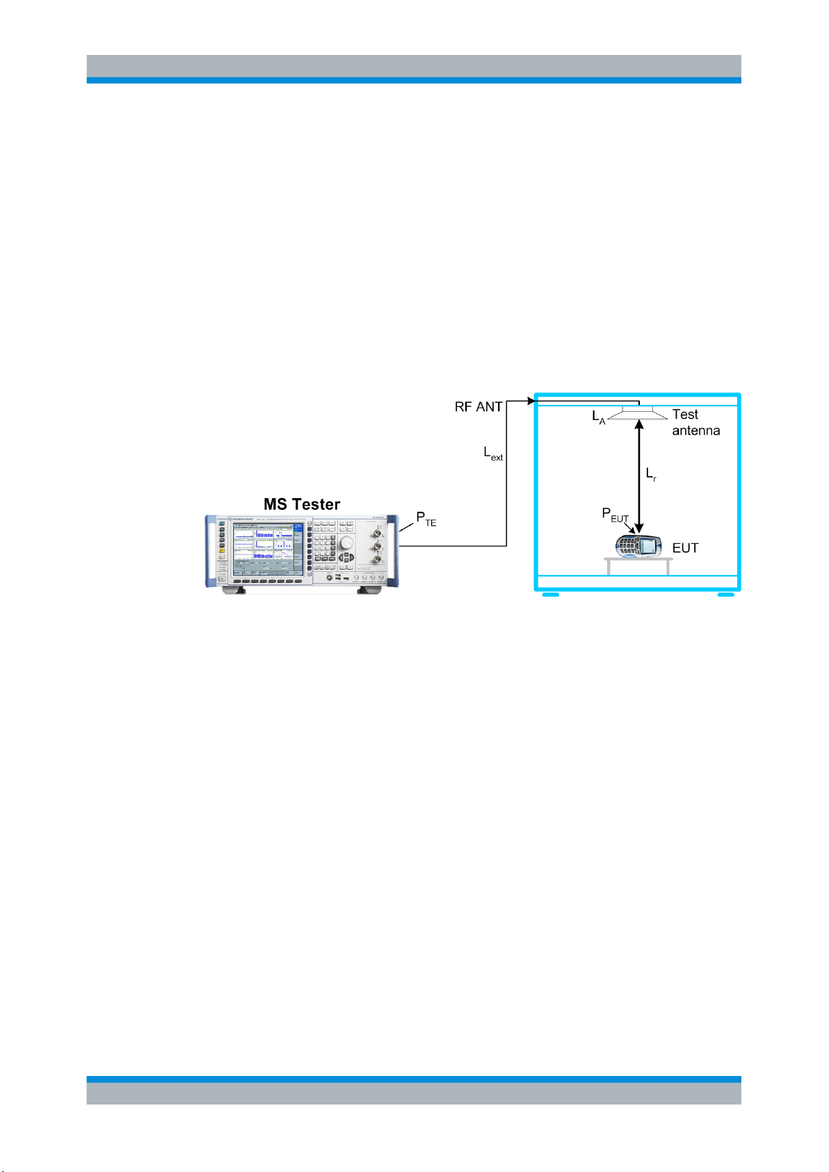
RF signals are attenuated on their way from the equipment under test (EUT) to the test
instrument and back. The total path loss in either direction includes the contribution of
the range path loss PLr due to the distance r between the EUT and the test antenna of
the Universal RF Shielding Box (including its connection to the RF ANT connector), the
loss PLA introduced by the antenna, and any loss PLex in the signal path between RF
ANT and the input/output connector of the test instrument. All these contributions may
depend on the signal direction.
Path Loss Measurement
Fig. 1-1: Path loss
We define the total path loss for the two signal directions as the difference between
transmitted and received powers:
● Input path loss/dB = P
ᅟ
= <EUT output power>/dBm – <RF input power at tester>/dBm
● Output path loss/dB = P
EUT, out
TE, out
– P
– P
TE, in
EUT, in
ᅟ= <Generator level of tester>/dBm – <Received signal level at the EUT>/dBm
Once the path loss values are known for a given EUT type, position, and RF connection
they can be reported to the test instrument as external attenuation factors ("External
Attenuation (Input)", "External Attenuation (Output)"). The tester will then correct all
power measurements by the reported input path loss and increase its RF generator level
to compensate for the output path loss.
In the definitions above the sign of the input and output path loss is in accordance with
the definition of external input and output attenuation factors ("Ext. Att. Input", "Ext. Att.
Output") in the R&S CMW and R&S CMU200.
3Application Sheet 1ZKD-18, M. Jetter, 05/2010 ─ 01
 Loading...