

Page 1

R&S®PULSE-K32/-K39
Pulse Sequencer Digital, Standard
Version and Expert Upgrade
User Manual
(;ÝV×2)
1179387302
Version 03
Page 2

This document describes the following software options:
●
R&S®PULSE-K32 standard version (1414.7077.22)
●
R&S®PULSE-K39 expert upgrade (1414.7125.22)
This manual describes software version V2.4 and later of the R&S®Pulse Sequencer Digital.
© 2022 Rohde & Schwarz GmbH & Co. KG
Muehldorfstr. 15, 81671 Muenchen, Germany
Phone: +49 89 41 29 - 0
Email: info@rohde-schwarz.com
Internet: www.rohde-schwarz.com
Subject to change – data without tolerance limits is not binding.
R&S® is a registered trademark of Rohde & Schwarz GmbH & Co. KG.
Trade names are trademarks of the owners.
1179.3873.02 | Version 03 | R&S®PULSE-K32/-K39
Throughout this manual, products from Rohde & Schwarz are indicated without the ® symbol , e.g. R&S®PULSE-K32 is abbreviated
as R&S PULSE-K32.
Page 3

R&S®PULSE-K32/-K39
Contents
1 Welcome to the R&S Pulse Sequencer Digital.................................. 11
1.1 Key features.................................................................................................................11
1.2 Accessing the R&S Pulse Sequencer Digital........................................................... 13
1.3 What's new...................................................................................................................13
1.4 Documentation overview............................................................................................13
1.4.1 User manuals and help................................................................................................. 13
1.4.2 Data sheets................................................................................................................... 14
1.4.3 Release notes and open source acknowledgment (OSA)............................................ 14
1.4.4 Application notes, application cards, white papers, etc.................................................14
1.5 Scope........................................................................................................................... 14
1.6 Notes on screenshots.................................................................................................14
Contents
2 Getting started......................................................................................16
2.1 Required options and licences.................................................................................. 16
2.2 Installing the software................................................................................................ 17
2.3 Licensing..................................................................................................................... 19
2.4 Starting the R&S Pulse Sequencer Digital for the first time................................... 21
2.5 Understanding the displayed information................................................................ 24
2.6 Software concept in brief........................................................................................... 29
2.7 Means of users interaction.........................................................................................31
2.8 Trying out the software...............................................................................................34
2.8.1 Completing the scenario that was automatically created upon start up........................ 35
2.8.2 Generating a simulated signal.......................................................................................36
2.8.3 Verifying the generated signal in the signal preview..................................................... 37
2.8.4 Launching the built-in wizard.........................................................................................38
2.8.5 Using the wizard to create a complex scenario.............................................................39
2.8.6 Saving and recalling settings........................................................................................ 44
2.8.7 Advanced features and examples.................................................................................45
2.9 Customizing the software.......................................................................................... 45
2.9.1 Customizing your workspace........................................................................................ 45
2.9.2 Changing colors and default configuration....................................................................46
2.10 Getting information and help..................................................................................... 48
3User Manual 1179.3873.02 ─ 03
Page 4

R&S®PULSE-K32/-K39
3 Preparing for use................................................................................. 50
3.1 Creating and using export plugins............................................................................50
3.2 PDW export plugin interface specification............................................................... 52
3.3 Destinations settings..................................................................................................56
4 Organizing the project data in repositories.......................................60
4.1 Repository settings.....................................................................................................60
4.2 Repository manager settings.....................................................................................63
4.3 How to manage the project data................................................................................66
5 Selecting a suitable scenario and creating scenarios......................70
5.1 Overview of the available scenarios and their complexity..................................... 70
5.2 Scenario settings........................................................................................................ 71
5.2.1 Common scenario settings............................................................................................72
Contents
5.2.2 Scenario-specific settings............................................................................................. 81
5.3 How to select and create a test scenario..................................................................86
6 Creating a pulse library....................................................................... 89
6.1 Basics on pulse signals and pulse generation........................................................ 89
6.2 Pulse settings..............................................................................................................89
6.2.1 Pulse name and comment............................................................................................ 89
6.2.2 Pulse timing settings..................................................................................................... 90
6.2.3 Modulation on pulse (MOP) settings............................................................................. 92
6.2.3.1 Common MOP parameters........................................................................................... 93
6.2.3.2 AM and ASK modulation............................................................................................... 93
6.2.3.3 FM and FSK modulation............................................................................................... 95
6.2.3.4 Chirp modulation........................................................................................................... 99
6.2.3.5 Phase modulation....................................................................................................... 104
6.2.3.6 Vector modulation....................................................................................................... 109
6.2.3.7 Noise........................................................................................................................... 110
6.2.4 Envelope graphs..........................................................................................................110
6.3 How to create a new pulse and adjust its settings.................................................111
7 Building pulse sequences.................................................................115
7.1 About the sequencing principles.............................................................................115
7.2 Sequence settings.....................................................................................................116
4User Manual 1179.3873.02 ─ 03
Page 5

R&S®PULSE-K32/-K39
7.2.1 Sequence description settings.....................................................................................116
7.2.2 Pulse repetition settings.............................................................................................. 121
7.2.3 Loop settings...............................................................................................................123
7.2.4 Fillers settings............................................................................................................. 124
7.2.5 Lists with multiple sequences......................................................................................125
7.3 How to create sequences and use the control elements...................................... 126
8 Defining and enabling inter-pulse modulation effects................... 134
8.1 IPM profiles settings................................................................................................. 137
8.1.1 Common IPM settings.................................................................................................137
8.1.2 IPM profiles settings....................................................................................................139
8.1.3 Edit list settings........................................................................................................... 149
8.1.4 Inter-pulse modulation (IPM) settings......................................................................... 150
Contents
8.2 How to create IPM profiles and vary pulse parameters.........................................154
9 Defining antenna patterns and antenna scans............................... 164
9.1 Overview of the main antenna parameters.............................................................164
9.2 Antenna pattern settings..........................................................................................167
9.3 Antenna scans settings............................................................................................184
9.4 How to create a library with antenna patterns and scans.....................................197
10 Emulating emitters.............................................................................209
10.1 Emitter settings......................................................................................................... 211
10.2 3D single emitter preview settings.......................................................................... 215
10.3 Emitters (Collection) settings.................................................................................. 217
10.3.1 Collection of emitters...................................................................................................218
10.3.2 Emitter properties........................................................................................................221
10.3.3 Mode editor settings....................................................................................................222
10.4 How to create and configure emitters.....................................................................224
11 Combining the signals of multiple emitters.................................... 230
11.1 Emitters (Collection) and localized emitters interleaving settings...................... 231
11.2 Emitters interleaving progress statistics................................................................235
11.3 Signal preview with interleaved and dropping statistics...................................... 236
11.4 Analyze interleaved signals..................................................................................... 237
12 Creating platforms............................................................................. 239
5User Manual 1179.3873.02 ─ 03
Page 6

R&S®PULSE-K32/-K39
12.1 About platforms........................................................................................................ 239
12.2 Platform settings.......................................................................................................239
12.2.1 Platform information.................................................................................................... 240
12.2.2 Emitter list................................................................................................................... 241
12.2.3 Properties of selected emitter..................................................................................... 245
12.2.4 Blank ranges of selected emitter.................................................................................248
12.3 Working with platforms............................................................................................ 249
13 Emulating receivers...........................................................................252
13.1 Receiver properties in localized emitters scenario............................................... 254
13.2 Receiver settings...................................................................................................... 256
13.3 DF system configuration settings........................................................................... 260
13.4 Receiver position settings in localized emitters and direction finding scenarios
.................................................................................................................................... 262
Contents
14 Working with imported signals.........................................................273
15 Visualizing and analyzing signals.................................................... 276
15.1 Signal preview settings............................................................................................ 276
16 Creating complex 2D scenarios with receiver and TX items......... 281
16.1 How to create scenarios with receiver and TX items............................................ 282
16.2 2D map settings........................................................................................................ 290
16.3 3D scan pair view settings....................................................................................... 294
16.4 Properties of TX items (emitters and platforms)....................................................299
16.4.1 Available TX items.......................................................................................................300
16.4.2 Properties of the selected TX item.............................................................................. 302
16.4.2.1 Properties (Type, alias name and configuration).........................................................302
16.4.2.2 Position settings (Static position and discrete position steps).....................................307
16.4.2.3 States.......................................................................................................................... 313
16.5 Moving emitters and platforms................................................................................314
16.6 Mode editor................................................................................................................325
16.7 Background emitters properties..............................................................................326
16.8 Platforms with multiple emitters..............................................................................328
16.8.1 TX items context menu............................................................................................... 330
16.8.2 Map area context menu.............................................................................................. 331
6User Manual 1179.3873.02 ─ 03
Page 7

R&S®PULSE-K32/-K39
16.8.3 Platform context menu................................................................................................ 331
16.9 Creating trajectories on a 2D map...........................................................................332
16.10 Using georeferenced maps...................................................................................... 333
16.11 Importing user icons.................................................................................................337
17 Configuring the simulation............................................................... 340
17.1 Signal calculation settings.......................................................................................340
17.2 Assign signals to destination.................................................................................. 343
18 Working with PDWs........................................................................... 347
18.1 How to import PDW lists and create output files................................................... 348
18.2 PDW import mechanism...........................................................................................353
18.3 PDW data settings.....................................................................................................355
18.4 PDW data import wizard settings............................................................................ 357
Contents
18.5 PDW list (Collection) settings.................................................................................. 360
18.6 PDW list (Collection) interleaving settings.............................................................361
18.7 PDW interleaving progress statistics......................................................................365
18.8 Signal preview with interleaved and dropping statistics...................................... 365
18.9 Analyze interleaving................................................................................................. 367
19 Defining complex modulation schemes and IPM profiles..............369
20 Defining and enabling marker signals............................................. 372
20.1 Marker settings..........................................................................................................372
20.2 How to configure and visualize markers................................................................ 374
21 Creating reports and documenting measurement results............. 378
21.1 Reporting settings.................................................................................................... 379
21.2 How to create test reports........................................................................................383
22 Performing administration tasks......................................................386
22.1 Setting general program settings............................................................................386
22.2 User administration.................................................................................................. 387
22.2.1 How to set and change user passwords..................................................................... 388
22.2.2 Related settings.......................................................................................................... 390
22.3 Defining storage locations....................................................................................... 391
22.3.1 How to set and change storage locations................................................................... 392
7User Manual 1179.3873.02 ─ 03
Page 8

R&S®PULSE-K32/-K39
22.3.2 Storage locations settings........................................................................................... 393
22.4 Speeding up calculation...........................................................................................395
22.4.1 How to optimize performance..................................................................................... 395
22.4.2 Related settings.......................................................................................................... 396
22.5 Configuring a proxy server...................................................................................... 397
22.6 Updating the software.............................................................................................. 398
23 Automation of R&S Pulse Sequencer Digital.................................. 399
23.1 Remote settings........................................................................................................ 400
23.2 Script manager settings........................................................................................... 401
23.3 SCPI log settings.......................................................................................................403
23.4 How to configure and enable remote control of R&S Pulse Sequencer Digital..404
23.5 How to log SCPI commands.................................................................................... 405
Contents
24 Remote control commands...............................................................407
24.1 Conventions used in SCPI command descriptions............................................... 407
24.2 Programming examples........................................................................................... 408
24.3 Common commands.................................................................................................408
24.4 Commands with similar syntax............................................................................... 409
24.5 Program settings.......................................................................................................425
24.6 Antenna pattern commands.....................................................................................428
24.7 Antenna scan commands.........................................................................................440
24.8 Signal mapping commands..................................................................................... 454
24.9 Emitter commands....................................................................................................457
24.10 Destination commands.............................................................................................460
24.11 Inter-pulse modulation commands......................................................................... 462
24.12 Import interface commands..................................................................................... 479
24.13 License server commands....................................................................................... 484
24.14 Marker commands.................................................................................................... 485
24.15 Plugin and reporting commands............................................................................. 490
24.16 Pulse commands.......................................................................................................496
24.17 Receiver commands................................................................................................. 510
24.18 Repository commands............................................................................................. 514
24.19 Scenario commands................................................................................................. 521
24.20 Moving emitters and receivers commands............................................................ 553
8User Manual 1179.3873.02 ─ 03
Page 9

R&S®PULSE-K32/-K39
24.21 Platform command....................................................................................................565
24.22 Sequence commands............................................................................................... 571
24.23 Status commands..................................................................................................... 580
24.24 System, message log and program commands.....................................................580
24.25 Signal preview commands....................................................................................... 582
24.26 List of remote commands........................................................................................ 584
25 Troubleshooting................................................................................. 606
25.1 Querying error messages.........................................................................................606
25.2 Collecting information for technical support......................................................... 610
25.3 Contacting customer support.................................................................................. 611
Annex.................................................................................................. 612
A Supported file types and file formats...............................................612
Contents
A.1 Movement files.......................................................................................................... 613
A.1.1 Waypoint file format.....................................................................................................613
A.1.2 Vector trajectory file format......................................................................................... 613
A.1.3 Trajectory description files...........................................................................................616
A.2 Vehicle description files (Used for smoothening)..................................................619
B Formula syntax...................................................................................621
C Plug-in programming API..................................................................624
C.1 Common functions................................................................................................... 624
C.2 Export plugin............................................................................................................. 629
C.3 IPM functions.............................................................................................................632
C.4 Reporting functions.................................................................................................. 634
C.5 Custom antenna pattern import functions............................................................. 636
C.6 List of Plugin Functions........................................................................................... 639
D Scripting API.......................................................................................640
D.1 Global script extensions.......................................................................................... 640
D.2 Newable script extensions....................................................................................... 642
D.2.1 QDir.............................................................................................................................642
D.2.2 QFile............................................................................................................................643
D.2.3 QFileDialog................................................................................................................. 644
9User Manual 1179.3873.02 ─ 03
Page 10

R&S®PULSE-K32/-K39
D.2.4 QMessageBox.............................................................................................................645
D.3 Script examples.........................................................................................................645
D.4 List of Script Objects and Methods.........................................................................647
E Common coding algorithms............................................................. 648
Glossary: Terms and abbreviations................................................. 649
Index....................................................................................................653
Contents
10User Manual 1179.3873.02 ─ 03
Page 11

R&S®PULSE-K32/-K39
1 Welcome to the R&S Pulse Sequencer Digi-
tal
The R&S Pulse Sequencer Digital is an application that generates complex pulse signals by using predefined, configurable test scenarios with different complexity. You can
simulate the signals of different emitter and receiver configurations, including antennas
and scan types.
The R&S Pulse Sequencer Digital software is a standalone, PC-based application that
creates simulated signals that you can export to a customized plugin. You can use
R&S Pulse Sequencer Digital for example to perform radar receiver tests and for
research and development.
Licenses
A license is not required for the demo version of the application.
To obtain a licence provider (R&S PULSE-LPA) and icense activation codes for
R&S PULSE-K32 or R&S PULSE-K39, contact Rohde & Schwarz support.
Welcome to the R&S Pulse Sequencer Digital
Key features
For details, see:
●
Description of the key features: Chapter 1.1, "Key features", on page 11.
●
Licences: Chapter 2.3, "Licensing", on page 19.
Installation
For details on installtion and activating licenses, see:
●
Installation instructions included in the delivery of the option.
●
Instructions described in Chapter 2.2, "Installing the software", on page 17.
1.1 Key features
R&S PULSE-K32 standard features:
●
Pulse definition
●
Modulation on pulse with all major formats like chirps, Barker codes, polyphase
codes, PSKs, AM, FM
●
Single pulse, pulse train generation with repetition count per pulse
●
Powerful sequencing tool with loops, nested loops, and fillers
●
Inter-pulse modulation of amplitude, phase, frequency, etc. values from pulse to
pulse
●
Calculation of signal under consideration of one-way free space propagation
according to emitter and receiver location on the 2D map
●
Import of PDW files
●
A "Platform " element that represents a real-world vehicle that can contain multiple
emitters.
11User Manual 1179.3873.02 ─ 03
Page 12

R&S®PULSE-K32/-K39
●
The realization is similar to the DF receiver model.
●
Platforms are mapped to a certain inertia profile (car, ship or plane).
●
Platforms have a tactical icon in dynamic scenarios.
●
Three-dimensional placement of emitters on the platform via 3-axis concept (X, Y
and Z).
●
A 2D and 3D preview of the emitter placement.
●
Emitter definition by signal, antenna diagram, antenna scan, attitude information,
EIRP, and carrier frequency
●
Antenna diagram definition and antenna scan definition
●
Antenna diagrams like pencil beams, cosecant beams, Gaussian diagrams, userdefined antenna diagrams, phased array antenna diagrams
●
Antenna scan types like helical scans, circular scans, conical scans
●
Receiver definition by antenna diagram, antenna scan, and attitude information
R&S PULSE-K39 expert features:
●
Allows merging of multiple PDW lists in the "PDW list (Collection)" scenario type or
multiple emitters in the "Emitters (Collection)" scenario into a single output file.
The feature uses a priority scheme for dropping or just merges the pulses even if
they overlap in time
●
Enhances the localized and direction finding scenario types by movement profiles
for emitters and receivers
●
Predefined line and arc movements for simple movement traces
●
Waypoint generation from user-defined "Traces" in the GUI
●
Waypoint import interface for complex movement traces
●
WGS84 waypoint interface and import of NMEA waypoints
●
Import of Google Earth and Google Maps .kmlfiles
●
East-North-Up (ENU) 2D vector trajectory interface (line, arc) for automatic waypoint generation
●
Motion interface for dynamics input (velocity vector or velocity magnitude) in ENU
and WGS84
●
Predefined waypoint files for land vehicles, ships, aircraft and spacecraft
●
User-definable and predefined vehicle description files for land vehicles, ships, aircraft and spacecraft
●
Smoothing of waypoints using vehicle description files
●
Use georeferenced maps as visual backgrounds for 2D and 3D map views.
●
Import the following map formats:
– GeoTIF
●
Create trajectories using the "Trace" function.
This function uses a series of user-selected points on the map (i.e. a user-defined
trace) to generate waypoints, automatically.
●
Dedicated direction finding scenario and receiver element with multiple antennas
and individual positioning
Welcome to the R&S Pulse Sequencer Digital
Key features
12User Manual 1179.3873.02 ─ 03
Page 13

R&S®PULSE-K32/-K39
●
Direction finding receiver definition with up to 20 antennas with individual positioning and pointing
1.2 Accessing the R&S Pulse Sequencer Digital
To open the application
► On your PC, select "Start > R&S Pulse Sequencer Digital > R&S Pulse Sequencer
Digital".
The software opens and per default displays the last opened workspace.
1.3 What's new
This manual describes software version V2.4 and later of the R&S®Pulse Sequencer
Digital.
Welcome to the R&S Pulse Sequencer Digital
Documentation overview
Compared to the previous version, it provides the following new features:
●
Added standard functions to copy and append or reorder items in various tables,
see Table 2-4.
●
Added functions for changing the timescale and activating the live stats preview in
the movement preview of the 2D map settings, see "Movement Preview"
on page 291.
●
Added interleaving dialog in PDW list collections, seeChapter 18.6, "PDW list (Col-
lection) interleaving settings", on page 361.
●
Reworked the mode editor dialog, see Chapter 10.3.3, "Mode editor settings",
on page 222.
●
Added function to import user defined icons for displaying TX/RX items, see Chap-
ter 16.11, "Importing user icons", on page 337.
1.4 Documentation overview
This section provides an overview of the R&S Pulse Sequencer Digital user documentation. Unless specified otherwise, you find the documents on the R&S Pulse
Sequencer Digital product page at:
https://www.rohde-schwarz.com/manual/pulse-sequencer/
1.4.1 User manuals and help
Introduces the R&S Pulse Sequencer Digital and describes how to start working with
the product. Includes basic operations, typical examples, general information, and the
13User Manual 1179.3873.02 ─ 03
Page 14

R&S®PULSE-K32/-K39
description of all software modes and functions. It also provides complete description
of the remote control commands with programming examples.
The contents of the user manuals are available as help in the R&S Pulse Sequencer
Digital. The help offers quick, context-sensitive access to the complete information.
All user manuals are also available for download or for immediate display on the Internet.
1.4.2 Data sheets
The data sheet contains the technical specifications of the R&S Pulse Sequencer Digital. It also lists the options and their order numbers as well as optional accessories.
See https://www.rohde-schwarz.com/brochure-datasheet/pulse-sequencer/.
1.4.3 Release notes and open source acknowledgment (OSA)
Welcome to the R&S Pulse Sequencer Digital
Notes on screenshots
The release notes list new features, improvements and known issues of the current
firmware version, and describe the firmware installation.
The open source acknowledgment document provides verbatim license texts of the
used open source software.
See https://www.rohde-schwarz.com/software/pulse-sequencer/.
1.4.4 Application notes, application cards, white papers, etc.
These documents deal with special applications or background information on particular topics.
See https://www.rohde-schwarz.com/application/pulse-sequencer/.
1.5 Scope
This user manual contains a description of the functionality that the software provides,
including remote control operation.
1.6 Notes on screenshots
When describing the functions of the product, we use sample screenshots. These
screenshots are meant to illustrate as much as possible of the provided functions and
possible interdependencies between parameters. The shown values may not represent
realistic usage scenarios.
14User Manual 1179.3873.02 ─ 03
Page 15

R&S®PULSE-K32/-K39
The screenshots usually show a fully equipped product, that is: with all options installed. Thus, some functions shown in the screenshots may not be available in your particular product configuration.
Welcome to the R&S Pulse Sequencer Digital
Notes on screenshots
15User Manual 1179.3873.02 ─ 03
Page 16

R&S®PULSE-K32/-K39
2 Getting started
This section describes the basic steps to be taken when starting up the R&S Pulse
Sequencer Digital for the first time.
● Required options and licences................................................................................16
● Installing the software............................................................................................. 17
● Licensing.................................................................................................................19
● Starting the R&S Pulse Sequencer Digital for the first time.................................... 21
● Understanding the displayed information................................................................24
● Software concept in brief.........................................................................................29
● Means of users interaction......................................................................................31
● Trying out the software............................................................................................34
● Customizing the software........................................................................................45
● Getting information and help...................................................................................48
Getting started
Required options and licences
2.1 Required options and licences
The R&S Pulse Sequencer Digital software is a standalone, PC-based application that
creates digital simulation data for the verification of software algorithms, digital training
and digital validation of ELINT systems.
The R&S Pulse Sequencer Digital is available in three operation modes:
●
Demo
A demo version that enables you to try out some of the main features of the application including access to the visualizations. However, you cannot export simulation data.
This option does not require a license.
●
Standard (R&S PULSE-K32)
A standalone application offering basic simulation features. Provides a range of
standard features and functionality, including exporting of simulated signal data
Requires a license.
●
Expert (R&S PULSE-K39)
An optional extension to R&S PULSE-K32 that provides expert functionality.
Requires a license.
Any of the licensed modes require a license dongle. The license provider R&S PULSELD is available as a separate product and must be ordered in addition to the software
licenses.
For information about licenses, see Chapter 2.3, "Licensing", on page 19.
16User Manual 1179.3873.02 ─ 03
Page 17

R&S®PULSE-K32/-K39
2.2 Installing the software
Software updates and the release notes describing the improvements and modifications are available for download at the product page https://www.rohde-schwarz.com/
software/pulse-sequencer/.
The following software components must be installed to run the R&S Pulse Sequencer
Digital successfully:
●
R&S License Server
●
VISA (Virtual Instrument Software Architecture)
The R&S License Server is installed automatically during installation of the R&S Pulse
Sequencer Digital. VISA can be installed directly during installation of the R&S Pulse
Sequencer Digital, or manually, independently of the R&S Pulse Sequencer Digital
installation. We recommend that you use the R&S VISA driver. The R&S VISA driver is
supplied with the R&S Pulse Sequencer Digital installation file, and can be installed
together with the R&S Pulse Sequencer Digital software.
Getting started
Installing the software
Software and hardware requirements
Minimum requirements:
●
Software
–
Microsoft®Windows 10, 64-Bit operating system (x64-based or x86-based processor)
●
Hardware
Table 2-1: Hardware requirements
AMD or Intel CPU Dual Core, 2 GHz
RAM ≥ 2 GB
Video NVIDIA Quadro 128 MB or ATI Radeon NVIDIA Quadro 128 MB or ATI
Video resolution ≥ 1280 x 1024 pixels ≥ 1920 x 1200 pixels
Network LAN 1 GB/s LAN 1 GB/s
Minimum requirements Recommended hardware
Radeon
To install the software
Download the R&S Pulse Sequencer Digital software form the Rohde & Schwarz website.
The R&S Pulse Sequencer Digital software consists of the file
PS-DIGITAL-Install <major>.<minor>.<build>.<release>-x64.msi.
1. Start the
PS-DIGITAL-Install <major>.<minor>.<build>.<release>-x64.msi
file.
The filename follows the naming conventions:
● <major>.<minor> is the software version
17User Manual 1179.3873.02 ─ 03
Page 18

R&S®PULSE-K32/-K39
● <build> is the build number.
● <release> indicates the release on the build date.
● x64 indicates that this is a 64-bit installation file.
2. Depending on your user rights, select one of the following:
a) Installation for all users (default)
b) Installation for current user only
Getting started
Installing the software
This is the day elapsed since 1 January 2000
This is 1/10 of the number of seconds elapsed since midnight.
You can run the software version with the extension x64 only on a 64-bit operating system, see "Software and hardware requirements" on page 17.
● Requires administrator rights
● Is a per-machine installation
● Project data and program data are common to all users
● Users keep their individual settings
● Does not require administrator rights
● Is a per-user installation
● Installation in %HomePath%
3. Choose the setup type.
4. Follow the installation instructions.
The installer performs the following actions:
● If enabled, installs the R&S VISA software on the PC
● Installs the R&S License Server
● Installs the R&S Pulse Sequencer Digital software including an uninstall tool
● Creates a shortcut on the desktop
● Creates the folder structure listed in Table 2-2.
Table 2-2: Default file location (software installation for all users)
File type File location
Program data
Project data (Repository database)
SDK files
Report files, startup log file, calculated data, volatile data
User settings (Workspace, etc.)
%PROGRAMFILES(X86)%\Rohde-Schwarz\
Pulse Sequencer Digital
(Path)
%PUBLIC%\Public\Documents\Rohde-Schwarz\
Pulse Sequencer Digital
(DataPath)
%HOMEPATH%
(HomePath or ReportPath)
%HOMEPATH%\AppData\Roaming\Rohde-Schwarz\
Pulse Sequencer Digital
18User Manual 1179.3873.02 ─ 03
Page 19

R&S®PULSE-K32/-K39
2.3 Licensing
A license is not required for the demo version of the R&S Pulse Sequencer Digital.
Running the R&S Pulse Sequencer Digital in standard mode requires a valid core
license R&S PULSE-K32, and, depending on the desired features, additional licenses
for options, like R&S PULSE-K39 for expert mode are required.
R&S PULSE-LD
The R&S Pulse Sequencer Digital software requires a smart card containing the software license to be connected to the PC when you are using the software. The
R&S PULSE-LD license provider contains the purchased software license and consists
of a smart card and a USB dongle. The R&S PULSE-LD is available as a separate
product and must be ordered in addition to the software.
To obtain the license provider R&S PULSE-LD and license activation codes for
R&S PULSE-K32 or R&S PULSE-K39, contact Rohde & Schwarz support.
Using the license provider R&S PULSE-LD
Getting started
Licensing
1. The R&S PULSE-LD license provider consists of a smart card in full format and a
USB smart card reader (dongle).
2. Break out the smart card in SIM format.
3. Twist out the upper part of the smart card reader.
19User Manual 1179.3873.02 ─ 03
Page 20

R&S®PULSE-K32/-K39
4. Insert the smart card with the chip facing upwards and the angled corner facing the
USB dongle, whose "Rohde & Schwarz" label is also facing upwards.
Insert the smart card as far as possible.
Getting started
Licensing
5. Twist the smart card reader back into its original state.
The license provider is ready for use on any USB interface.
6. Connect the license provider to the PC the R&S Pulse Sequencer Digital is running
on.
The R&S License Server, that is installed automatically with the R&S Pulse
Sequencer Digital installation, detects the license provider and the software licenses.
The software is ready to use.
Activating licenses
When you order a license and a license provider at once, the purchased licenses are
already registered, activated and are delivered on the license provider.
If you purchase a license, for example R&S PULSE-K39, at a latter time, you receive a
license key, registered for your license provider and need to activate the license.
1. Connect the license provider to the PC the R&S Pulse Sequencer Digital is running
on.
2. Open the "R&S License Server".
3. Select "Activate".
4. In the License Key field, enter the registered license key you have received.
5. Follow the instructions.
20User Manual 1179.3873.02 ─ 03
Page 21

R&S®PULSE-K32/-K39
6. Restart the "R&S License Server".
7. Start the R&S Pulse Sequencer Digital.
Missing licenses
If the R&S Pulse Sequencer Digital complains about missing licenses, run the R&S
License Server Manager browser application.
1. On the R&S Pulse Sequencer Digital PC, select "Windows" > "Start" > "R&S
License Server" > "R&S License Server Manager".
2. Check if the required R&S PULSE-LD license is visible in the "Licenses > Licence
providers" tab.
3. Check if the required R&S PULSE-K32 or R&S PULSE-K39 licenses are visible in
the "Licenses > Licences" tab.
For more information, on the R&S License Server:
● In the "R&S License Server Manager" web interface, click the "Help" icon.
● Open Windows start menu and select "Open License Server Manual" to access
Getting started
Starting the R&S Pulse Sequencer Digital for the first time
the R&S License Server user manual in PDF format.
2.4 Starting the R&S Pulse Sequencer Digital for the first
time
1. Check that you have a valid license registered on your PC.
Note: If you do not have a license provider and license registered yet, you can run
the software in demonstration mode. Continue with this procedure and select
"Demo Mode" from the list of options.
2. On your PC:
a) Select "Start > R&S Pulse Sequencer Digital > R&S Pulse Sequencer Digital"
or
b) Double click the shortcut icon on the desktop.
The "Pulse Sequencer Digital Mode / License Server" dialog opens.
21User Manual 1179.3873.02 ─ 03
Page 22

R&S®PULSE-K32/-K39
Getting started
Starting the R&S
Pulse Sequencer Digital for the first time
Note: Dialog options correspond to registered licenses. You cannot select an
option in the dialog unless the required license is registered. "Installed Options"
displays the available licenses.
3. In the "Pulse Sequencer Digital Mode / License Server" dialog, select the required
mode from the available options.
a) For example, select "Pulse Sequencer Digital Mode = Demo".
This option is always available, with or without license.
Select this option if you want to experiment with the R&S Pulse Sequencer Digital functionality without producing PDWs.
b) If the respective license or combination there of are available and registered,
select one of the following options:
● "Pulse Sequencer Digital Mode = Standard (requires R&S PULSE-K32)"
Select this mode if you want to create PDWs from scenarios that do not
require advanced functions such as DF and maps.
● "Pulse Sequencer Digital Mode = Expert (requires R&S PULSE-K32 and
R&S PULSE-K39)"
Select this mode if you require advanced functions such as DF, interleaving, movements and maps.
4. Select "Start".
The "Startup Assistant" opens.
22User Manual 1179.3873.02 ─ 03
Page 23

R&S®PULSE-K32/-K39
Getting started
Starting the R&S
5. Select "Create a repository" > "Finish".
6. Follow the instructions. Use the default settings when starting R&S Pulse
Sequencer Digital for the first time.
A new repository ("New_<Year>-<Month>-<Day>T<Time>") is created that contains a simple scenario ("SimplePulseTrain").
Your workspace resembles the one shown in the following figure.
Pulse Sequencer Digital for the first time
See also:
● Figure 2-1 (in Chapter 2.5, "Understanding the displayed information",
on page 24)
● Chapter 2.6, "Software concept in brief", on page 29
● Chapter 2.8, "Trying out the software", on page 34
23User Manual 1179.3873.02 ─ 03
Page 24

R&S®PULSE-K32/-K39
2.5 Understanding the displayed information
The following figure shows an example test scenario during software operation. The
different information areas are labeled. They are explained in more detail in the following sections.
Getting started
Understanding the displayed information
Figure 2-1: R&S Pulse Sequencer Digital default workspace: understanding the displayed information
1 = Title bar
2 = Menu bar with standard functions, e.g. save/open file etc.
3 = Toolbar
4 = Project tree (repository tree)
5 = Screens for individual scenarios
6 = Work area
4+6 = Workspace
7 = Taskbar with indication of enabled remote control incl. details like IP address (if enabled), information
on the required highest security level (if enabled) and access to active dialogs
The user interface of the R&S Pulse Sequencer Digital offers an intuitive operating
concept. Operation is similar to any operating system. All menus and dialogs use
known elements, e.g., selection lists, checkboxes, and entry fields.
24User Manual 1179.3873.02 ─ 03
Page 25

R&S®PULSE-K32/-K39
Menu bar
Table 2-3: Content of the menu bar
Getting started
Understanding the displayed information
File Repository Configure
●
New Repository
●
Load or Manage Repositories
●
Save Repository
●
Import Repository Archive
●
Export Repository
●
Clear Workspace
●
Open Workspace
●
Save Workspace
●
Save Workspace As
●
Exit
Quick access
to currently
loaded repository
●
Destinations
●
Remote
Control
●
Colors
●
Settings
Toolbars
The R&S Pulse Sequencer Digital offers two toolbars.
Standard functions can be performed via the icons in the main toolbar at the top of the
screen.
Tools Window Help
●
●
●
Script
Console
Wizard
●
●
●
●
●
●
Message
Log
SCPI Log
MinSize All
Windows
Cascade
Close All
Screen 1 ..
4
●
●
●
●
●
●
●
●
Online
Help
Documentation
Examples
SDK
Tutoriaks
Find
conncetors
Debug
Information
About
Figure 2-2: Standard functions in the main toolbar
1 = Save as: stores current workspace configuration
2 = Repository:
- = Creates a repository
- = Opens "Manage Repository" dialog for loading, discarding or exporting repositories
3 = Project tree:
- = Creates a scenario
- = Starts a wizard to create an emitter or pulse train in current repository
4 = Opens the "Destinations" dialog
5 = Logs:
- = Opens the "Message Log" window
- = Opens the "SCPI Log" window
6 = Screen: switches between the virtual screens
7 = Opens the "Program Settings" dialog
8 = Help:
- = Opens the "Example Files" folder
- = Opens the "SDK" folder
- = Opens the help documentation folder containing help documents
- = Displays context-sensitive help topic for currently selected element
9 = Hardcopy: copies current dialog to the clipboard
25User Manual 1179.3873.02 ─ 03
Page 26

R&S®PULSE-K32/-K39
Functions relating to the "Project Tree" can be performed via the icons in the toolbar
below the main toolbar.
Figure 2-3: Functions in the Project Tree toolbar
1 = Filters out the displayed elements in the "Project Tree" and displays, for example, only the uppermost
node, i.e. scenarios ("Show = Only Scenarios")
2 = Moves the elements within a node up/down in the "Project Tree"
3 = Expand/collapse all nodes in the "Project Tree"
Virtual screens
Using the R&S Pulse Sequencer Digital you can handle several scenarios with even
comprehensive settings at the same time. You can arrange the dialogs across multiple
screens logically, so that you can easily switch between them. You can, for example,
assign the subset of antenna dialogs to one screen and the pulse and modulation dialogs to another.
Getting started
Understanding the displayed information
Repository tree
The repository tree shows the content of all currently loaded repositories. Repository
elements are indicated with the assigned icons, their names, and the first comment
line.
= Name, see "Name and comment" on page 26
1
2 = First comment line
Name and comment
Each repository element is identified with its unique name and optional description
entered in the comment field. The description can contain several lines; new line is
added by pressing [Shift+Enter].
See also "Dialog names" on page 27.
26User Manual 1179.3873.02 ─ 03
Page 27

R&S®PULSE-K32/-K39
1 = A unique name to indicate the element in the repository
2 = Description; the first line is displayed in the repository tree
Context-sensitive menus
All user interface controls provide a context-sensitive menu. Context-sensitive menus
are accessed with a right mouse click on the control.
Getting started
Understanding the displayed information
1
= Context menu of an icon
2 = Context menu of a parameter
Tooltips
Tooltips indicate the possible value range of a parameter or list overview information on
current settings.
= Tooltip of a setting parameter, indicating the allowed value range
1
2 = Tooltip with detailed information on a setting
Dialog names
The name of a dialog indicates its content or the functionality this dialog covers. The
used naming convention helps you to recognize which database element you are configuring, to which scenario it belongs and what its current name is.
"<Repository Element>: <Scenario Name> -> <Function Name>"
27User Manual 1179.3873.02 ─ 03
Page 28

R&S®PULSE-K32/-K39
1 = Repository element
2 = Scenario name
3 = Function name
Undocking dialogs
If your workspace contains several simultaneously opened dialogs, you can undock
dialogs and distribute them also outside the workspace, for example place them on a
second monitor.
1
= Undocks the dialog
Interactive 3D displays
Getting started
Understanding the displayed information
Several dialogs display the configured settings as 2D or as interactive 3D models or
full 3D antenna radiation patterns.
Turning the mouse wheel zooms in and out on these dialogs. Moving the mouse while
holding the left mouse key rotates the 3D view around its origin.
Interactive 2D map
Drag&drop elements into the 2D map or pan and zoom to change the displayed map
area.
Keyboard shortcuts
Keyboard shortcuts are available for the most common functions in the software.
28User Manual 1179.3873.02 ─ 03
Page 29

R&S®PULSE-K32/-K39
2.6 Software concept in brief
The following is brief introduction to the software concept and the way it handles files
and settings.
Repository
The R&S Pulse Sequencer Digital organizes the data in repositories.
A repository is a file-based database located on the local hard drive or on a network
storage drive.
Repositories are entirely managed by the R&S Pulse Sequencer Digital. They can be
password protected against unauthorized access. Repositories can be exported as
archives and shared among multiple users if they are located on a network drive. Several users can have read permission to load and use the same repository simultaneously. However, only one user can have a write permission at a time.
When you create a repository in one operational mode, it is not always compatible with
the other modes. For a description see "Create" on page 64.
Getting started
Software concept in brief
For more information, see Chapter 4, "Organizing the project data in repositories",
on page 60.
Scenario
The scenario is the top-level description of the signals to be generated.
The type of the scenario determines which kind of signal is calculated and how this signal is processed. A more complex scenario combines several signals. Scenarios can
also contain information about the time variation of the signals.
Starting a scenario creates the simulated data and exports them to user-written plugins.
For more information, see Chapter 5, "Selecting a suitable scenario and creating sce-
narios", on page 70.
Platform
A platform is a group of up to 8 emitters assigned to a single vehicle. A platform can
be static or moving. A platform is characterized by its icon, list of emitters, position and
trajectory. The emitters on a platform can be individually configured.
For more information, see Chapter 12, "Creating platforms", on page 239.
Emitter
Emitters emulate radar systems. The emitter combines a sequence, an antenna scan,
and an antenna pattern to one logical unit.
An emitter can work in more than one operating mode and switch between them. The
operating mode is a description of the radar purpose, such as scanning, searching or
tracking. For example, an airport surveillance radar can switch between different scan
types to observe its airspace.
29User Manual 1179.3873.02 ─ 03
Page 30

R&S®PULSE-K32/-K39
Each mode can have individual antenna and signal configuration. Multiple beams are
possible within a mode.
For more information, see Chapter 16, "Creating complex 2D scenarios with receiver
and TX items", on page 281.
Antenna
The antenna characterizes the radiation pattern of the emitter. Typical radar antennas like the phase array antennas can adapt their radiation pattern dynamically,
depending on the operating mode the radar is working in. For example, an antenna
can use a cosecant beam in scan mode and pencil beam in track mode.
Antennas can have various scan types. The scan type describes the movement of the
antenna. For example, circular, sector and custom.
For more information, see Chapter 9, "Defining antenna patterns and antenna scans",
on page 164.
Receiver
Getting started
Software concept in brief
Receivers are used to model direction finding systems. They comprise of up to 20
individual antennas with individual patterns and positioning relative to a direction finding system.
Option: R&S PULSE-K39 required for direction finding.
For more information, see Chapter 13, "Emulating receivers", on page 252.
Sequence
A sequence describes how pulses are arranged to form a waveform. The most simple
sequence comprises one pulse that is repeated with a constant PRI (pulse repetition
interval). Typical sequences however are rather complex; they can contain pulse definitions, waveforms, and sequencing elements such as repetitions and loops.
The sequence is a logical description. It cannot directly be represented as an I/Q
waveform.
For more information, see Chapter 7, "Building pulse sequences", on page 115.
Pulse
In the R&S Pulse Sequencer Digital, pulses are the fundamental building block of
any signal. Pulses are described mathematically with their amplitude (envelope), the
applied modulation on pulse (MOP) and the enabled marker signals. One single pulse
description is however not sufficient to calculate (and process) a signal; pulses have to
be organized in a sequence, and assigned to an emitter.
For more information, see Chapter 6, "Creating a pulse library", on page 89.
Imported signals
30User Manual 1179.3873.02 ─ 03
Page 31

R&S®PULSE-K32/-K39
In addition to creating pulse signals you can also load PDW files and use them in
sequences.
For more information, see Chapter 18, "Working with PDWs", on page 347.
Plugins
A plugin is an extension to the standard functions of the R&S Pulse Sequencer Digital.
For even more flexibility, plugins can contain variables.
To export the simulated signal from the R&S Pulse Sequencer Digital, you can write
"export" plugins that are customized to your interfaces. The export plugin enables you
to extract the digital simulation data from the application in a defined format and export
it to different formats or directly stream the data.
For more information, see "How to import and assign user defined plugins"
on page 369.
Getting started
Means of users interaction
2.7 Means of users interaction
This chapter provides an overview on how to work with the R&S Pulse Sequencer Digital and describes the manual operation of the software and also the alternative ways of
operation.
There are two ways to operate the R&S Pulse Sequencer Digital:
●
Manual operation:
Run the software on your PC and use the mouse and/or keyboard.
●
Remote control:
Create programs to automate settings, tests and measurements. The software is
controlled by a program, running on the same or on another computer.
This way of operation is described Chapter 23, "Automation of R&S Pulse
Sequencer Digital", on page 399.
Basic operation concept
This section lists settings and functions that are common to the dialogs and are performed in the same manner throughout the software. You can use them alternatively or
complementary.
As described in Chapter 2.6, "Software concept in brief", on page 29, the R&S Pulse
Sequencer Digital software is based on a relational database that organizes database
elements within repositories. Database elements are indicated by their names; within
one repository, element names must be unique (see "Name and comment"
on page 26).
31User Manual 1179.3873.02 ─ 03
Page 32

R&S®PULSE-K32/-K39
Creating elements
Once created, database elements can be used by other elements within the same
repository. Elements can be created in both the bottom-up and the top-down direction,
or in a combination of these two methods:
●
Bottom-up: you can create your pulse and waveform library first, then build
sequences, create scenarios, and use the created sequences or assign them to
emitters.
●
Top-down: create your scenario, create emitter, define the antenna pattern/scan,
define the used sequence, and define the pulses and waveforms.
Getting started
Means of users interaction
1
= Repository, one or more within the database
2 = Scenario level; scenarios describe one or more emitters and one or more sequences
3 = Emitter level; emitters are described among others with antenna patterns and antenna scans
4 = Antenna patterns and antenna scans
5 = Sequence level; sequences are built of one or more pulses or waveforms
6 = Pulse and waveform level
7a, 7b = Creating elements at any level with clone and copy
For information on the naming conventions and description of the database elements,
see Chapter 2.6, "Software concept in brief", on page 29.
Handling database elements
While creating database elements, consider also the following possibilities:
●
Change
Files describing elements are stored once but can be used several times. When
one file is changed, its parent elements are also updated.
●
Clone
Elements can be cloned to create a deep copy of the database element.
●
Delete
Elements can be deleted if they are not referenced by other elements.
●
Copy
If two repositories are opened in the project tree, a drag and drop operation creates
a copy of the selected element and all referenced elements.
32User Manual 1179.3873.02 ─ 03
Page 33

R&S®PULSE-K32/-K39
Standard function in the context menus
Each dialog with settings belonging to a "higher-level" element provides standard functions to:
●
Assign existing elements
●
Create elements
●
Edit the existing assigned element.
You can access these functions from the context-sensitive menus of the icons listed in
Table 2-4.
Table 2-4: Overview of the used icons and their functions
Icon Name Function/Description
Getting started
Means of users interaction
<Function> Menu
(the name changes depending on
the situation)
More Select
Pulse, Waveform Creates repository element
Antenna Pattern, Antenna Scan,
Sequence
Emitter, receiver
3D, 2D diagram
Smart menu with several options,
depending on the current element
and situation:
●
New (Item)
●
Append item
●
Prepend item
●
Insert Item
●
Insert Item Before/After
●
Delete Item
●
Clear (Selection)
●
Edit
●
Select (from a list)
●
Rename
●
Import/Export
Edit
New
Accesses a dialog with detailed settings
Append item, Remove item, Delete Appends or removes item, deletes all
items
Left/Right , Up/Down Reorders items
Copy and append Copies the selected line of the table
and appends it at the end of the table
Select Selects a table row or an item for
editing
33User Manual 1179.3873.02 ─ 03
Page 34

R&S®PULSE-K32/-K39
Icon Name Function/Description
Standard functions for elements handling
The following standard direct interaction functions are supported:
●
Double-click
Opens the selected element for editing
●
Clone
Creates a copy of the selected element
●
Drag and Drop
A drag and drop operation:
– Creates a copy of the selected element, together with all referenced elements
– Assigns an element to a 2D view
– Importsa repository
– Imports waveform files into the repository
●
Mouse wheel
Turning the mouse wheel zooms in and out.
Getting started
Trying out the software
Enable/Disable Activates or deactivates settings
Hardcopy, Print Copies current screen or dialog to
the clipboard;
Prints current diagram
Split window Detaches the diagram and opens it
in a separate window
Name depends on contents Opens a settings dialog. For exam-
ple, "Visualization settings" or "Program settings".
Description of alternative methods
This manual describes the manual interaction with the software via the menus. Many
elements that can be accessed form menus can also be accessed by clicking an icon
or using the context menu. Alternative procedures are only described if they deviate
from the standard operating procedures.
Throughout the manual, the term "select" refers to any of the described methods.
2.8 Trying out the software
This chapter introduces the most important functions and often used settings of the
R&S Pulse Sequencer Digital step by step. The complete description of all functions
and their usage is provided in the corresponding main chapters of this user manual.
Prerequisite
The software is running and started up as described in Chapter 2.4, "Starting the
R&S Pulse Sequencer Digital for the first time", on page 21.
34User Manual 1179.3873.02 ─ 03
Page 35
R&S®PULSE-K32/-K39
The software is manually operated. Try out the following:
● Completing the scenario that was automatically created upon start up..................35
● Generating a simulated signal.................................................................................36
● Verifying the generated signal in the signal preview...............................................37
● Launching the built-in wizard...................................................................................38
● Using the wizard to create a complex scenario.......................................................39
● Saving and recalling settings.................................................................................. 44
● Advanced features and examples...........................................................................45
2.8.1 Completing the scenario that was automatically created upon start up
We assume that you have started the software as described in Chapter 2.4, "Starting
the R&S Pulse Sequencer Digital for the first time", on page 21. Your workspace
resembles the one shown on Figure 2-1 (see section Chapter 2.5, "Understanding the
displayed information", on page 24).
Your repository contains:
●
"P1": an unmodulated pulse with pulse width of 100 us and rise and fall times set to
zero
●
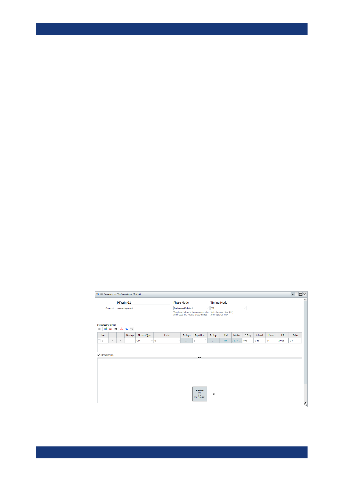
"PTrain 01": a sequence containing one single pulse, "P1". This pulse is processed
once ("Rep. Count = 1") and has a pulse repetition interval "PRI = 200 us".
Getting started
Trying out the software
To create a sequence with 10 pulses, each having a PRI of 1 ms
1. In the repository tree, select "Scenario > Sequences > PTrain 01".
2. In the "Sequence Description" table, select:
a) "Rep. Count = 10"
b) "PRI = 1 ms"
For information on the provided settings, see:
● Chapter 7.2, "Sequence settings", on page 116
35User Manual 1179.3873.02 ─ 03
Page 36

R&S®PULSE-K32/-K39
● Chapter 6.2.2, "Pulse timing settings", on page 90
To assign the sequence to the scenario
When created by the "Wizard", the sequence is automatically assigned to the scenario.
If not, proceed as follows:
1. In the repository tree, select "Scenario > PTrain 01".
The "Scenario" dialog opens and displays a block diagram of the signal flow.
2. In the block diagram, select "Sequence" and select the icon to open the context
menu.
3. Select "Select > PTrain 01".
The status indicator in the "Sequence" block is green.
The status indicator in the "Signal Calculation" block is still red.
2.8.2 Generating a simulated signal
Getting started
Trying out the software
The initial situation is the configuration described in "To start the signal calculation"
on page 37.
To set the output target for the created signal
1. In the repository tree, select "Scenario > SimplePulseTrain".
The "Scenario" dialog opens and displays a block diagram of the signal flow.
2. In the block diagram, select "Signal Generation" and select the icon to open the
context menu.
3. Select "Config > Target > Destination".
A list of the available Destinations appears.
A check mark indicates the currently selected destination.
4. Select a destination from the list.
The block name changes to indicate the selected destination.
5. The block diagram shows the updated settings.
36User Manual 1179.3873.02 ─ 03
Page 37

R&S®PULSE-K32/-K39
The "Info" area shows a status indication and displays information and warnings
about the scenario. For example, if the destination does not support elements used
in the scenario, the information displays here. The created signal is output is PDWs
to the export plugin.
You can now change some of the calculation and output settings.
Getting started
Trying out the software
6. Select "Signal Calculation > Config > Config".
7. In the "Signal Calculation Settings" dialog, select "Output".
If all preconditions for signal generation are fulfilled, the "Calculate" button is active and
you can start signal calculation.
To start the signal calculation
► In the "Scenario" dialog, select "Calculate".
The R&S Pulse Sequencer Digital calculates the simulated signal according to the
selected settings and shows the current progress.
A green indicator in the "Signal Calculation" block confirms that the calculation is
completed. The line between the "Signal Calculation" and the "Signal Generation"
blocks confirms that the calculated signal can be transmitted to the selected target.
For information on the provided settings, see:
● Chapter 5.2, "Scenario settings", on page 71
2.8.3 Verifying the generated signal in the signal preview
It is often useful to check the generated signal visually, before you transfer it to the
Destinations. The R&S Pulse Sequencer Digital provides a built-in function, the "Signal
Preview", to represent the generated signal in a graphical form.
The initial situation is the configuration described in "To start the signal calculation"
on page 37.
37User Manual 1179.3873.02 ─ 03
Page 38

R&S®PULSE-K32/-K39
To open the "Signal Preview" and visualize the generated signal
► In the "Scenario" dialog, select "Signal Calculation > Results > View" and select the
name of the calculated waveform.
Getting started
Trying out the software
Figure 2-4: Signal Preview
2.8.4 Launching the built-in wizard
To help you get familiar with the software, the R&S Pulse Sequencer Digital provides a
built-in startup assistant, the " Wizard".
You can access this "Wizard":
●
On an application start:
That is, each time you start the software
●
On demand:
That is, any time during operation when you need a fast configuration of few settings.
To start the built-in wizard
► In the tool bar, select "Tools > Wizard".
The "Startup Assistant" opens.
38User Manual 1179.3873.02 ─ 03
Page 39

R&S®PULSE-K32/-K39
Getting started
Trying out the software
2.8.5 Using the wizard to create a complex scenario
The main application field of the R&S Pulse Sequencer Digital is the generation of
pulsed signals. This example uses the "Wizard" to introduce the way you can create
and define antenna patterns, antenna scans, emitters, etc. and interact with the software.
To create a new single emitter scenario
1. Start the "Wizard", see Chapter 2.8.4, "Launching the built-in wizard", on page 38.
2. In the assistant dialog, select "Create Emitter".
Confirm with "Next".
39User Manual 1179.3873.02 ─ 03
Page 40

R&S®PULSE-K32/-K39
Getting started
Trying out the software
3. Use the default settings and select "Waveform Characteristics > MOP > Barker".
Select "Next".
40User Manual 1179.3873.02 ─ 03
Page 41

R&S®PULSE-K32/-K39
Getting started
Trying out the software
4. Confirm with "Finish".
41User Manual 1179.3873.02 ─ 03
Page 42
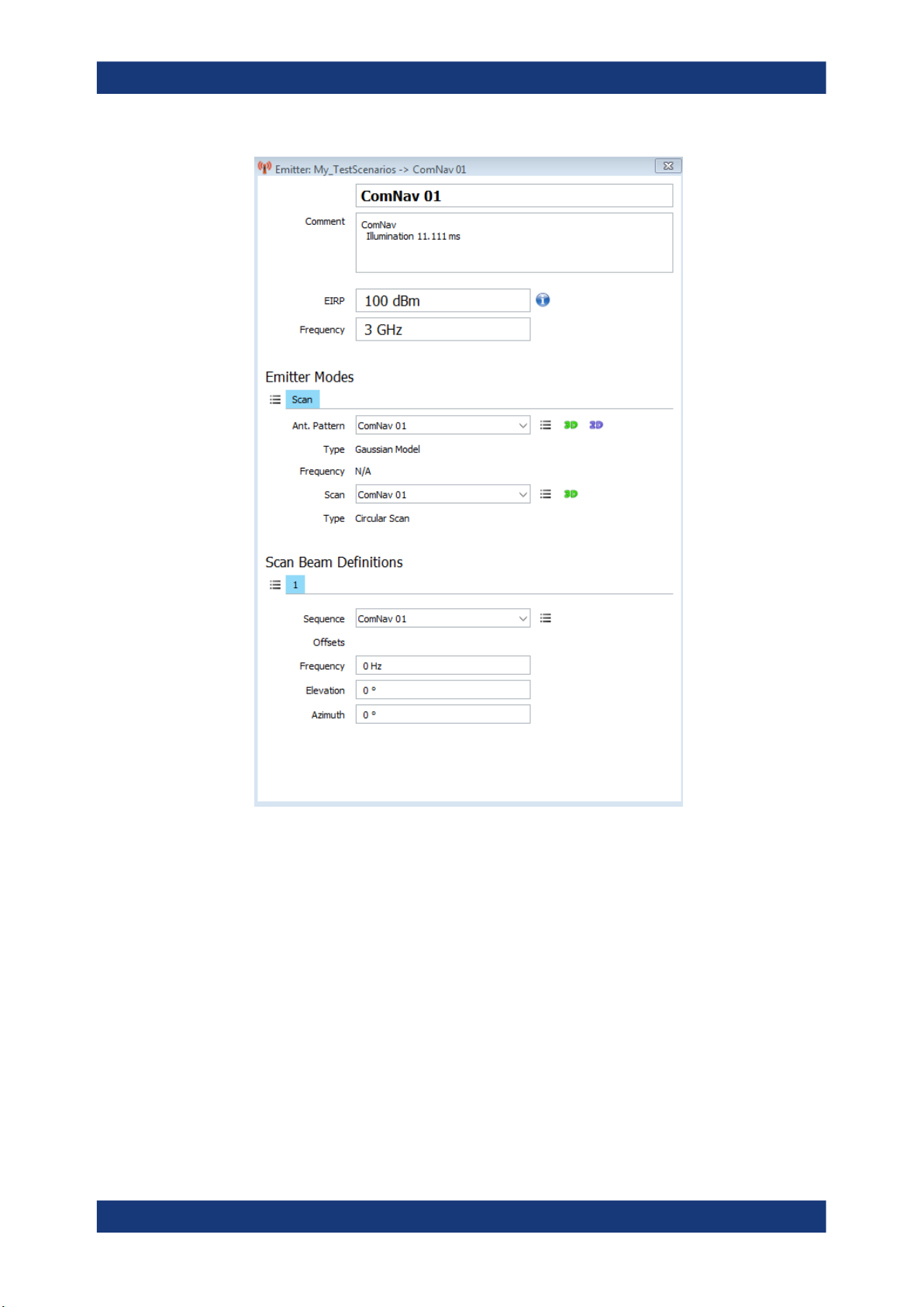
R&S®PULSE-K32/-K39
Getting started
Trying out the software
The software creates the scenario automatically with all required elements, e.g.
one new emitter ("ComNav 01"), one new sequence ("ComNav 01"), new pulse
("ComNav 01"), etc.
For information on the provided settings, see:
● Chapter 10.1, "Emitter settings", on page 211
● Chapter 9.2, "Antenna pattern settings", on page 167
● Chapter 9.3, "Antenna scans settings", on page 184
● Chapter 6.2.3, "Modulation on pulse (MOP) settings", on page 92
To visualize the signal received by a static receiver
1. Open the automatically created emitter-based scenario ("ComNav 01").
42User Manual 1179.3873.02 ─ 03
Page 43

R&S®PULSE-K32/-K39
Getting started
Trying out the software
2. In the "Emitter" section on the block diagram, select the "3D" icon.
43User Manual 1179.3873.02 ─ 03
Page 44

R&S®PULSE-K32/-K39
The "3D Single Emitter" dialog displays a live plot of the normalized signal power
level at the receiver and an interactive 3D view of the emitter antenna pattern and
scan.
3. Use the mouse wheel to zoom in and out.
4. To rotate the 3D view around its origin, left mouse click. Keep the key pressed and
move the mouse.
For information, see Chapter 16, "Creating complex 2D scenarios with receiver and
TX items", on page 281
2.8.6 Saving and recalling settings
Repositories are automatically saved when you exist the application. We recommend
that you set a meaningful repository name before closing the application.
To rename the repository
Getting started
Trying out the software
Your workspace shows one automatically created repository, "New_yyyy_mm_tttt".
1. In the repository tree, select "Repository > New_yyyy_mm_tttt".
2. Change the name. Optionally, enter a comment.
For example, enter "General > Name > K32 and K39 Tests" or a "Comment >
Repository with test files".
To enter a new line in the comment field, press [Shift+Enter].
3. Close the dialog.
To save the repository
A yellow data base icon
changes.
► In the menu bar, select "File > Save Repository > _Repository name_".
The repository is stored in the data path set during the program installation.
To exit the software
► Close the application software.
If the current repository contains unsaved changes, you are prompt to store or
ignore them.
Note: Unsaved changes are lost.
in the repository tree indicates that there are unsaved
For more information, see:
●
Chapter 2.9.1, "Customizing your workspace", on page 45
●
Chapter 4.3, "How to manage the project data", on page 66
44User Manual 1179.3873.02 ─ 03
Page 45

R&S®PULSE-K32/-K39
2.8.7 Advanced features and examples
With these first steps, you have gained an impression of the provided functionality.
You find a comprehensive description of the full range of capabilities in the following
sections:
●
Chapter 6.3, "How to create a new pulse and adjust its settings", on page 111
●
Chapter 7.3, "How to create sequences and use the control elements",
on page 126
●
Chapter 5.3, "How to select and create a test scenario", on page 86
●
Chapter 21.2, "How to create test reports", on page 383
●
Chapter 9.4, "How to create a library with antenna patterns and scans",
on page 197
●
Chapter 10.4, "How to create and configure emitters", on page 224
●
Chapter 16.1, "How to create scenarios with receiver and TX items", on page 282
●
Chapter 8.2, "How to create IPM profiles and vary pulse parameters", on page 154
●
Chapter 20.2, "How to configure and visualize markers", on page 374
●
"How to import and assign user defined plugins" on page 369
Getting started
Customizing the software
2.9 Customizing the software
You can change default application settings to adapt the user interface to your needs.
● Customizing your workspace.................................................................................. 45
● Changing colors and default configuration..............................................................46
2.9.1 Customizing your workspace
A workspace comprises the repository tree on the left side with one or more loaded
repositories, and the working area with one or more screens. You can create several
workspaces with different repositories assigned to them. You can save and load a
user-defined workspace and switch between the different workspaces.
To save a workspace
We assume that you have opened or created a repository and opened one or more
dialogs in one of the screens.
1. In the menu bar, select "File > Save Workspace/Save Workspace As" or use the
save icon in the toolbar.
2. In the explorer, enter a filename, e.g. MyWorkspace.pswk and confirm with "Ok".
Per default, the *.pswk file is stored in the application data directory.
45User Manual 1179.3873.02 ─ 03
Page 46

R&S®PULSE-K32/-K39
To load a workspace
1. In the menu bar, select "File > Open Workspace".
Existing default and user-defined workspaces are listed.
2. Select a workspace.
The workspace opens. All dialogs and repositories associated with the workspace
are displayed.
To close a workspace
You can close a workspace if you do not need it no longer or you need to switch to a
different one.
► In the menu bar, select "File > Clear Workspace".
The workspace is closed.
Closing the workspace unloads all repositories and closes all dialogs.
You can open a workspace again, see "To load a workspace" on page 46.
Getting started
Customizing the software
2.9.2 Changing colors and default configuration
You can change the default application settings, for example, change the display colors
or change default settings of the R&S Pulse Sequencer Digital.
To customize the display colors
1. In the menu bar, select "Configure > Colors".
46User Manual 1179.3873.02 ─ 03
Page 47
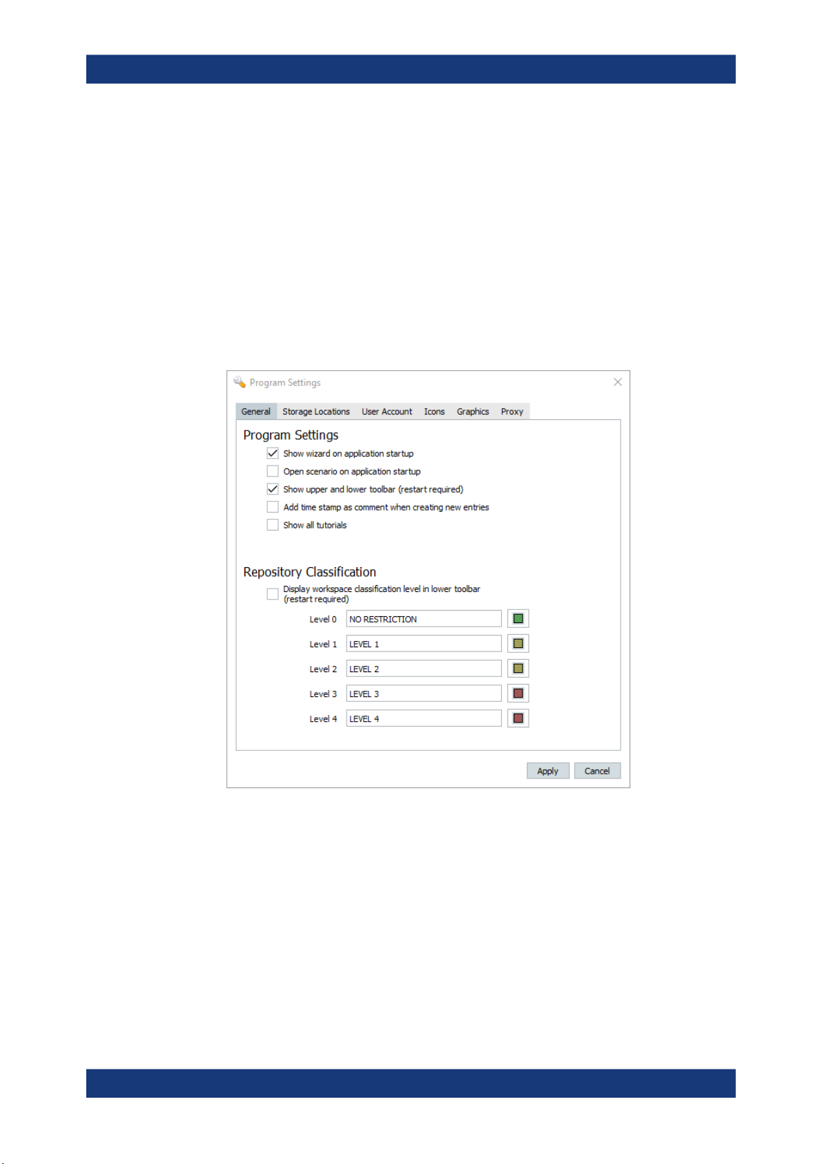
R&S®PULSE-K32/-K39
1 = Color scheme
2 = Assigns colors to the different display elements
2. Select a predefined color scheme and, if necessary, adjust the display colors indi-
vidually.
3. Adjust the display colors of the individual elements, e.g select "Traces > Magni-
tude" and change the default color.
4. Select "Save As" to store your custom color profile in a file, e.g. MyColors.col.
To change the general program settings
1. In the menu bar, select "Configure > Settings".
Getting started
Customizing the software
2. Change the settings, select the colors indicating the different security levels.
For information on the security levels, see "General Repository Settings"
on page 60.
3. Confirm with "Apply".
To set the size and color scheme of the hardcopies
For documentation purposes, you can create a hardcopy or screenshot of the current
screen or dialog. Hardcopies can be sent to the printer or stored to the clipboard.
1. To adjust the hardcopy size, in the menu bar, select "Configure > Settings > Graph-
ics".
47User Manual 1179.3873.02 ─ 03
Page 48
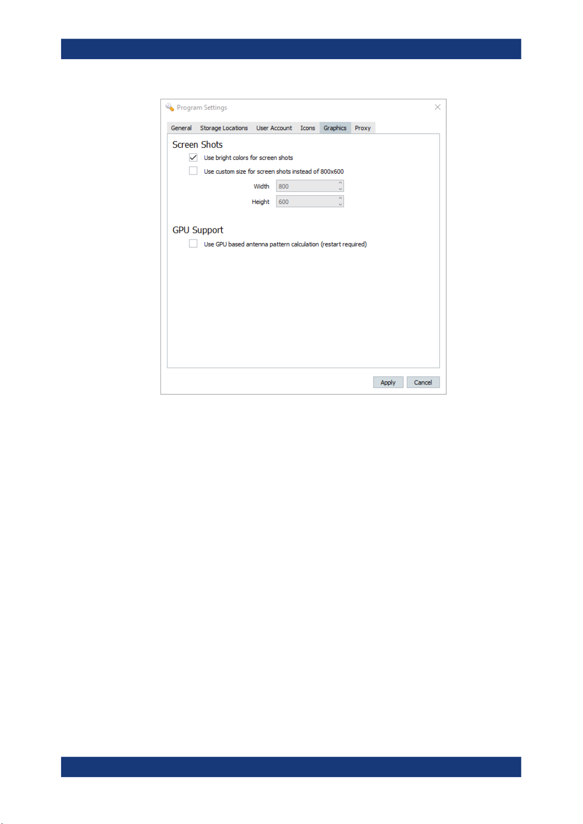
R&S®PULSE-K32/-K39
Getting started
Getting information and help
2. Select "Use bright colors for screenshots > On" e.g. for ink-saving printing.
Brighter colors are used for all graphical screens instead of the ones set in the current color scheme.
3. Select "Use custom size for screenshots instead of 800x600 > On" and set the
"Width" and "Height" in number of pixels.
4. Confirm with "Apply".
The settings provided on the other tabs in the "Program Settings" dialog are explained
in:
●
Chapter 22, "Performing administration tasks", on page 386
2.10 Getting information and help
If any questions or problems concerning the R&S Pulse Sequencer Digital arise, an
extensive online help system is provided in the software and can be consulted at any
time.
The integrated help system provides the description of all functions. The help system is
context-sensitive and provides information specifically for the current operation or setting to be performed. In addition, general topics provide an overview on complete tasks
or function groups and background information.
48User Manual 1179.3873.02 ─ 03
Page 49

R&S®PULSE-K32/-K39
Calling up Help
► To display the "Help" dialog for the currently focused screen element, e.g. a setting
in an opened dialog, select the "Help" icon on the toolbar or press F1.
The "Help" dialog is displayed. A topic containing information about the focused
element is displayed. If no context-specific help topic is available, a more general
topic or the "Contents" tab is displayed.
The "Help" toolbar provides buttons with standard navigation functions. The "Help"
window contains several tabs:
● "View" - shows the selected help topic
● "Contents" - contains a table of help contents
● "Index" - contains index entries to search for help topics
● "Bookmarks" - contains custom bookmarks
● "Search" - provides text search
To close the Help window
Getting started
Getting information and help
The index is sorted alphabetically. You can browse the list, or search for entries
in the list
► Select the "Close" icon in the upper right corner of the help window.
49User Manual 1179.3873.02 ─ 03
Page 50

R&S®PULSE-K32/-K39
3 Preparing for use
Overview
The R&S Pulse Sequencer Digital runs as a standalone, PC-based application that
creates simulated PDW datastreams that you can export to a customized plugin.
The software hands the simulated data to a so-called "destination", which wraps a
user-written plugin that receives the data.
You can add as many destinations as you need. To enable you to export a PDW datastream, you need to assign an export plugin to a destination.
R&S Pulse Sequencer Digital plugins are user-configurable, enabling you to define the
export content and format.
See:
●
Chapter 3.1, "Creating and using export plugins", on page 50
●
Chapter 3.2, "PDW export plugin interface specification", on page 52
●
Chapter 3.3, "Destinations settings", on page 56
●
Chapter C, "Plug-in programming API", on page 624.
Preparing for use
Creating and using export plugins
3.1 Creating and using export plugins
To use export plugins in R&S Pulse Sequencer Digital, you need to load a plugin of this
type and map it to a destination.
The following chapters explain how to perform these steps.
For a detailed description of the programming API for the plugin, see Chapter C.2,
"Export plugin", on page 629.
Creating an export plugin
R&S Pulse Sequencer Digital is delivered with the necessary resources to enable you
to create plugins to export the simulated signals.
We recommend using an application such as Visual Studio to open the resource files
and create the plugin. However, you can use an alternative compiler if you prefer. The
plugin exports an extern "C" interface which ensures the compatibility of the DLL.
Access:
1. Perform one of the following:
● In the menu bar, select "Help > SDK > Export_PDW > src"
● On the main toolbar, select the icon "Open SDK folder > Export_PDW > src".
This folder contains example resource files that you can modify as required.
2. Open the solution file, PulseSequencer_Plugin.sln.
3. Change the build configuration to "Release".
50User Manual 1179.3873.02 ─ 03
Page 51

R&S®PULSE-K32/-K39
4. Rebuild the solution.
The export plugin is in the "Export_PDW > bin" folder and ready for loading into
R&S Pulse Sequencer Digital.
Debugging the export plugin
To debug the DLL
1. Load the plugin project in Visual Studio or your preferred compiler.
2. Set the configuration to "Debug".
3. Set the target path to the location of the R&S Pulse Sequencer Digital executable
file.
4. Start the debugger.
PS-DIGITAL.exe starts.
5. Ensure that the PDB debug file is in the same folder as the DLL so that the debug-
ging symbols load correctly and you can set the breakpoints.
Normally the file location selected automatically by the debug build is correct.
Preparing for use
Creating and using export plugins
6. When the DLL is loaded into R&S Pulse Sequencer Digital, you can start debug-
ging the plugin code in Visual Studio.
Loading an export plugin
To load an export plugin in to R&S Pulse Sequencer Digital, follow the same steps as
for other plugin types.
For details, see "To import a plugin" on page 369.
Navigate to the "SDK > Export_PDW > bin" folder to select the export plugin.
Mapping plugins to destinations
When an export plugin is loaded as described in Loading an export plugin, you can
map it to a destination in R&S Pulse Sequencer Digital.
Access:
1. Perform one of the following:
● In the menu bar, select "Configure" > "Destinations"
● In the block diagram of a scenario, select "Signal Generation" > "Config" >
"Destinations".
The "Destinations" dialog opens.
51User Manual 1179.3873.02 ─ 03
Page 52

R&S®PULSE-K32/-K39
2. To add a new destination, in "Available Destinations" select "Add a new destination".
A new entry displays at the end of the list, assigned with the next free number.
3. To edit the destination name, double-click in the "Destination" field.
4. Select an available plugin fom the "Plugin" drop-down list.
Preparing for use
PDW export plugin interface specification
5. To edit the name or comment parameters, or to change the selected DLL, select
"Edit".
The "Plugin" dialog opens.
6. Edit the plugin variables on the right as required.
The plugin is mapped to the specified destination and ready for use in a scenario.
For a description of how to assign signals to destinations, see Chapter 17.2, "Assign
signals to destination", on page 343.
3.2 PDW export plugin interface specification
The export plugin that R&S Pulse Sequencer Digital uses for the simulated signals is
user-configurable. You can adapt the plugin for streaming or transferring the data as
you require, including the content of the data.
The format of the PDW data at the export plugin interface function is a
Rohde & Schwarz proprietary format as described in this chapter. In the plugin, the
user is free to extract any needed information and adapt the data formats or representation of the values to map it to any needed format.
Depending on the scenario you are using and your export needs, some of the following
parameters might not be necessary.
Parameters that are not set represent an invalid value. Parameters that do not have an
invalid representation are guaranteed to be valid.
The serialized data uses little endian byte order.
52User Manual 1179.3873.02 ─ 03
Page 53

R&S®PULSE-K32/-K39
Preparing for use
PDW export plugin interface specification
Data type
The invalid value depends on the data type:
●
uint8/16/32
The invalid case is defined as all 1's in bit representation, which means 0xFF,
0xFFFF, ... in hex.
For unsigned integers, it is the definition of the maximum value that is possible,
therefore the valid data range is limited by 1.
For example, for uint8 the data range is [0, 254] in decimal representation, as 255
is used to indicate the invalid case.
●
int16
The invalid case is defined as 0x8000, which represents the minimum value
-32768. Therefore the valid data range for int16 is [-32767, 32767].
●
float32
The invalid case is defined as 0x7F7FFFFF, which represents the maximum available float number regarding IEEE-754.
Table 3-1: PDW export plugin interface parameters
Data type Parameter Byte size Range Invalid Unit Description
uint8 version 1 [0x00, 0xFF] - - PDW format version.
Initial version = 0x00.
uint16 tx_platform_id 2 [1, 65534] 0xFFFF - User configured plat-
form ID
uint16 tx_id 2 [1, 65534] 0xFFFF - User configured emitter
ID (per emitter mode)
uint8 tx_plat-
form_emit_id
uint8 tx_list_id 1 [1, 254] 0xFF -
uint8 rx_id 1 [1, 254] 0xFF - Database ID of the
uint8 rx_antenna_id 1 [1, 254] 0xFF - Antenna ID of receiver
uint64 toa 8 [0,
1 [1, 254] 0xFF - Emitter index inside
platform (if platform
emitter)
List index in multi-emitter scenario:
●
Emitter index for
single emitter in list
●
Platform (parent)
index if emitter is
platform emitter
receiver
(list index in repository
tree view)
- ns TOA
18.446.744.073,
...] (s)
uint32 freq 4 [0, 42.94] (GHz) - 10 Hz Absolute center fre-
quency
uint32 pulse_width 4 [0, 4294] (s) - ns Pulse width
int32 level 4 [-200, 200]
(dBm)
- 0.01 dBm Absolute level
53User Manual 1179.3873.02 ─ 03
Page 54

R&S®PULSE-K32/-K39
Preparing for use
PDW export plugin interface specification
Data type Parameter Byte size Range Invalid Unit Description
uint8 modulation 1 [0x00, 0xFF] - - Modulation flag
See Modulation flags
uint16 bandwidth 2 [0, 65534] (kHz) 0xFFFF kHz Bandwidth
uint32 rise_time 4 [0, 4294] (s) - ns Pulse rise time
uint32 fall_time 4 [0, 4294] (s) - ns Pulse fall time
uint8 marker_mask 1 [0x00, 0x0F] - - Marker bits (4321)
uint16 azimuth 2 [0, 360] (deg) 0xFFFF 0.1 deg Tx azimuth
int16 elevation 2 [-90, 90] (deg) 20x8000 0.1 deg Tx elevation
float32 distance 4 [-1e9, +1e9] (m) 0x7F7FFFFF m Tx distance to Rx origin
uint16 rx_antenna_azi
muth
int16 rx_antenna_el
evation
float32 longitude 4 [-180, 180]
float32 latitude 4 [-90, 90] (deg) 0x7F7FFFFF deg Tx latitude coordinate in
float32 altitude 4 [-1e9, +1e9] (m) 0x7F7FFFFF m Tx altitude coordinate
float32 east 4 [-1e9, +1e9] (m) 0x7F7FFFFF m Tx east coordinate
float32 north 4 [-1e9, +1e9] (m) 0x7F7FFFFF m Tx north coordinate
float32 up 4 [-1e9, +1e9] (m) 0x7F7FFFFF m Tx up coordinate (ENU).
uint16 yaw 2 [0, 360] (deg) 0xFFFF 0.1 deg Tx yaw
2 [0, 360] (deg) 0xFFFF 0.1 deg Rx antenna azimuth
2 [-90, 90] (deg) 0x8000 0.1 deg Rx antenna elevation
0x7F7FFFFF deg Tx longitude coordinate
(deg)
in deg (7-8 positions
after decimal point)
deg (7-8 positions after
decimal point)
(ENU).
Reference coordinate is
Rx position.
(ENU).
Reference coordinate is
Rx position.
int16 pitch 2 [-90, 90] (deg) 0x8000 0.1 deg Tx pitch
uint16 roll 2 [0, 360] (deg) 0xFFFF 0.1 deg Tx roll
uint32 speed 4 [0, 5999] (m/s) 0xFFFFFFFF 0.01 m/s Absolute speed of Tx
Total byte size
reserved_field 2
reserved_field 167
256
Reserved field for future
additions
movement
Reserved field for future
additions
54User Manual 1179.3873.02 ─ 03
Page 55

R&S®PULSE-K32/-K39
Modulation flags
Table 3-2 shows the 8-bit encoding of the pulse modulation type.
Table 3-2: Modulation flags
modulation hex code bin code
unmodulated 00 00000000
fm 01 00000001
fm-step 02 00000010
2-fsk 03 00000011
4-fsk 04 00000100
8-fsk 05 00000101
16-fsk 06 00000110
32-fsk 07 00000111
64-fsk 08 00001000
Preparing for use
PDW export plugin interface specification
msk 09 00001001
chirp-generic 10 00010000
chirp-linear-up 11 00010001
chirp-linear-down 12 00010010
chirp-linear-triangular 13 00010011
chirp-linear-piecewise 14 00010100
chirp-sine 15 00010101
barker-2 20 00100000
barker-3 21 00100001
barker-4a 22 00100010
barker-4b 23 00100011
barker-5 24 00100100
barker-7 25 00100101
barker-11 26 00100110
barker-13 27 00100111
polyphase-frank 30 00110000
polyphase-p1 31 00110001
polyphase-p2 32 00110010
polyphase-p3 33 00110011
polyphase-p4 34 00110100
bpsk 35 00110101
55User Manual 1179.3873.02 ─ 03
Page 56

R&S®PULSE-K32/-K39
modulation hex code bin code
qpsk 36 00110110
8psk 37 00110111
phase-generic 3F 00111111
am-standard 40 01000000
am-lsb 41 01000001
am-usb 42 01000010
am-lsb-usb 43 01000011
am-step 44 01000100
ask 45 01000101
16-qam 50 01010000
32-qam 51 01010001
64-qam 52 01010010
Preparing for use
Destinations settings
128-qam 53 01010011
256-qam 54 01010100
noise 60 60 01100000
unknown FE 11111110
EOF FF 11111111
See also:
●
Chapter C.2, "Export plugin", on page 629
3.3 Destinations settings
Access:
► Perform one of the following:
● In the menu bar, select "Configure" > "Destinations"
● In the block diagram of a scenario, select "Signal Generation" > "Config" >
"Destinations".
56User Manual 1179.3873.02 ─ 03
Page 57

R&S®PULSE-K32/-K39
Figure 3-1: Destinations: understanding the displayed information
1 = Displays all available destinations
2 = Adds/removes destinations
3 = Information and parameters for available destinations
4 = Plugin variables for currently selected destination
5 = Resets all variables for selected plugin
6 = Information and parameters of variables for selected plugin
Preparing for use
Destinations settings
Settings
Available destinations....................................................................................................57
└ Add, delete, delete all..................................................................................... 57
└ No................................................................................................................... 58
└ Type................................................................................................................ 58
└ Destination......................................................................................................58
└ Plugin..............................................................................................................58
└ Edit..................................................................................................................58
Plugin variables.............................................................................................................58
└ Reset variables...............................................................................................58
└ No................................................................................................................... 58
└ Variable........................................................................................................... 58
└ Value............................................................................................................... 59
Available destinations
Displays all available destinations in a repository. Destinations displayed here are
available in all scenarios.
Add, delete, delete all ← Available destinations
Standard functions for items handling.
You cannot delete a destination that is assigned in a scenario. First remove the assign-
ment, then delete the destination from the list.
Remote command:
DESTination:ADD on page 461
DESTination:DELete on page 461
DESTination:CLEar on page 461
57User Manual 1179.3873.02 ─ 03
Page 58

R&S®PULSE-K32/-K39
No ← Available destinations
Displays the destination number assigned automatically when added.
If you delete a destination from the list, the numbers below it are automatically reas-
signed.
Remote command:
DESTination:SELect on page 417
Type ← Available destinations
Plugin type icon assigned automatically for export plugins.
Destination ← Available destinations
User-configurable name of the destination. To edit the name, select the field.
Remote command:
DESTination:NAME on page 418
Plugin ← Available destinations
Selects a plugin from the drop-down list.
The list contains all export plugins available in "Project tree > Plugins".
Remote command:
DESTination:PLUGin:NAME on page 461
Preparing for use
Destinations settings
Edit ← Available destinations
Opens the "Plugin" dialog where you can edit the name and comment fields or load a
new DLL file.
For detailed information on importing plugins, see "How to import and assign user
defined plugins" on page 369.
Plugin variables
Displays the variables for the current destination.
Remote command:
DESTination:PLUGin:VARiable:CATalog on page 492
DESTination:PLUGin:VARiable:SELect on page 492
Reset variables ← Plugin variables
Resets the variable parameters to the default, removing customizations. The reset
applies to all parameter values, including values not currently selected in the list.
Remote command:
DESTination:PLUGin:VARiable:RESet on page 493
No ← Plugin variables
Displays the automatically assigned plugin variable number.
Remote command:
DESTination:PLUGin:VARiable:SELect:ID on page 493
Variable ← Plugin variables
Displays the variable type.
58User Manual 1179.3873.02 ─ 03
Page 59

R&S®PULSE-K32/-K39
This parameter is for information only.
Value ← Plugin variables
Displays the value of the variable. To edit the values, double-click in the field.
Remote command:
DESTination:PLUGin:VARiable:VALue on page 493
Preparing for use
Destinations settings
59User Manual 1179.3873.02 ─ 03
Page 60

R&S®PULSE-K32/-K39
4 Organizing the project data in repositories
This section explains the basic repository concept and informs you briefly how the software database is built.
An introduction to the concept of elements handling is provided in "Creating elements"
on page 32.
4.1 Repository settings
Access:
► In the project tree, double-click the repository name.
The repository tree shows the content of the currently loaded repositories.
Organizing the project data in repositories
Repository settings
Settings:
General Repository Settings......................................................................................... 60
└ Info..................................................................................................................61
└ Classification...................................................................................................61
└ Antenna Cross Polarization > Attenuation......................................................61
Comment.......................................................................................................................61
Users.............................................................................................................................62
Storage..........................................................................................................................62
General Repository Settings
Provides general information related to repository management.
The "General" tab.
60User Manual 1179.3873.02 ─ 03
Page 61

R&S®PULSE-K32/-K39
Info ← General Repository Settings
Provides information like the name of the author and the date of creation.
"Name"
"Author"
"Created"
"Version"
Remote command:
REPository:CATalog? on page 417
REPository:CREate on page 417
REPository:SELect on page 418
REPository:REMove on page 419
REPository:AUTHor on page 515
REPository:DATE on page 516
REPository:VERSion on page 517
Organizing the project data in repositories
Repository settings
When a new repository is created, it is named automatically but you
can rename it afterwards.
The automatically assigned names follow the syntax:
New_<yyyy-mm-dd><T><hhmmss>, where <yyyy-mm-dd> and
T<hhmmss> indicate the current date and time respectively.
Indicates the author.
Automatically assigned date and time indication.
Repository version.
Classification ← General Repository Settings
Classification information is assigned to each repository to set the security level.
"Level"
"Disable copy operations to lower level repositories"
Remote command:
REPository:SECurity on page 517
Antenna Cross Polarization > Attenuation ← General Repository Settings
Sets the attenuation level used to calculate the cross-polarized antenna patterns, see
"Polarization" on page 171.
Remote command:
REPository:XPOL:ATTenuation on page 517
Comment
Enter a short description of the repository.
Remote command:
REPository:COMMent on page 419
"Level 0" is the lowest level that means no restrictions and "Level 4"
is the highest one. Elements belonging to a repository with higher
level cannot be copied to a repository with lower one.
If more than one repository is loaded, the workspace displays the
highest required classification level, see Chapter 2.5, "Understanding
the displayed information", on page 24.
See also "To change the general program settings" on page 47.
If enabled, you cannot copy repository elements for repositories with
higher classification level to repositories with lower one.
61User Manual 1179.3873.02 ─ 03
Page 62

R&S®PULSE-K32/-K39
Users
Provides settings related to user management.
For detailed information, see Chapter 22.2, "User administration", on page 387.
Storage
This tab provides settings necessary to configure the default storage folder for the
repositories.
Organizing the project data in repositories
Repository settings
"Path"
Remote command:
REPository:PATH? on page 516
"Obtain Write Permission"
"Remove Write Lock"
Displays the location (network or local folder) the repository is stored
in.
Repositories allow the simultaneous access from several users. If a
user with write permission has opened a repository, this write permission is exclusive. Another user will be granted with the write permission only after the first user had closed the repository or removed it
from its workspace.
You can request an exclusive write permission only on a repository
that is not opened by another user with write permission.
See also:
●
"Discovered Repositories on the Mass Storage" on page 64
●
"To obtain write permission on a repository" on page 69
The R&S Pulse Sequencer Digital locks any improperly or unexpectedly closed repository and indicates this situation with a red lock symbol
in the "Repository Tree". A locked repository can be unlocked
only from the same PC and by the same user with write permission
that had opened the repository before.
See "To remove write lock that results from a previously crashed ses-
sion" on page 609.
62User Manual 1179.3873.02 ─ 03
Page 63

R&S®PULSE-K32/-K39
"Reveal in Explorer"
Remote command:
REPository:FILename? on page 516
REPository:SAVE on page 516
4.2 Repository manager settings
Organizing the project data in repositories
Repository manager settings
You can open the repository file structure in the Windows Explorer.
Note: Do not change the repository content by changing the file
structure in the Windows Explorer.
To move or share repositories with other users, always use the
"Export/Import Repository Archive" function.
See:
●
"To create and export a repository archive" on page 68
●
"To import a repository archive via the menu bar" on page 68
Access:
► In the menu bar, select "File > Load and Manage Repository".
Figure 4-1: Repository Manager: understanding the displayed information
1 = Default repository path (DataPath), see also Table 2-2
2 = Mode/license type of repository, see "Create" on page 64
3 = Add custom path for repository discovery for saving and possibly sharing repositories, alternative to
the DataPath and the HomePath
4 = Add the home path set during installation
5 = Add user's home path
6 = User home path (HomePath)
The "Repository Manager" comprises the setting for managing the repository files
and archives on the mass storage.
63User Manual 1179.3873.02 ─ 03
Page 64

R&S®PULSE-K32/-K39
Settings:
Discovered Repositories on the Mass Storage.............................................................64
Create........................................................................................................................... 64
Load.............................................................................................................................. 64
Export............................................................................................................................65
Copy to..........................................................................................................................65
Delete............................................................................................................................65
Refresh..........................................................................................................................65
Add Path....................................................................................................................... 65
Add Install Path, Add Home Path..................................................................................65
Remove Path................................................................................................................ 66
Discovered Repositories on the Mass Storage
Lists all found directories and the repository files they contain.
You can change the column width and order.
A red lock symbol
the following situations:
●
Repository is opened by another user with explicit write access.
●
Insufficient user right for the particular repository.
●
Insufficient user right on the file system (directory) the repository is stored in.
Try to:
●
Wait until the repository has been closed and try to obtain exclusive write permission, see "To obtain write permission on a repository" on page 69.
●
Change your current user or use a user with different role, see "To change the
default user used to access repositories" on page 389.
●
Log in as user with sufficient (write) access rights on the file system.
Remote command:
REPManager:CATalog? on page 517
Organizing the project data in repositories
Repository manager settings
on the database icon in the "Repository Manager" indicates one of
Create
Adds a repository in the selected directory.
The "Mode" ("Demo" / "Standard" / "Expert") indicates in which operation mode you
created the repository (see Chapter 2.1, "Required options and licences", on page 16).
The following rules apply to repositories:
●
Repositories created in the R&S PULSE-K32 can be opened with R&S PULSEK39
The repository is irreversibly updated to R&S PULSE-K39 complexity.
●
Repositories created in R&S PULSE-K39 cannot be opened with R&S PULSEK32.
●
Repositories created in the demo version cannot be opened with R&S PULSE-K32
or R&S PULSE-K39.
●
Repositories created in the original R&S Pulse Sequencer (RF) application can be
imported into R&S Pulse Sequencer Digital.
See also Chapter 22.3, "Defining storage locations", on page 391.
Load
Loads and displays the selected repository in the workspace.
64User Manual 1179.3873.02 ─ 03
Page 65

R&S®PULSE-K32/-K39
See "To load a repository" on page 67.
Remote command:
REPManager:LOAD on page 518
Export
Exports the selected repository to an archive file.
See "To create and export a repository archive" on page 68.
Remote command:
REPManager:EXPort on page 519
Copy to
Copies the selected repository to a new location.
The R&S Pulse Sequencer Digital automatically copies all relevant files and database
elements.
Delete
Deletes the entire repository from the permanent mass storage, if:
●
The current user has write permission, see Table 22-1.
●
The repository is not opened by another user with write permission.
Remote command:
REPManager:DELete on page 518
Organizing the project data in repositories
Repository manager settings
Refresh
Refreshes the list of found repository files.
Add Path
Opens the "Select Folder" dialog that is similar to the Windows Explorer.
Navigate to the required directory and load it. Found repository files are displayed in
the list.
See also "To set the storage location for repositories" on page 393.
Remote command:
REPManager:PATH:ADD on page 519
REPManager:CATalog? on page 517
Add Install Path, Add Home Path
Adds and loads the directory automatically. Found repository files are displayed in the
"Discovered Repositories on the Mass Storage" on page 64.
Where:
●
"Add Install Path" opens the DataPath directory.
Per default, this directory is the same displayed in "Repository Manager" (see Fig-
ure 4-1).
●
"Add Home Path" opens the HomePath directory.
For information on the default file paths, see Table 2-2.
See also Chapter 22.3, "Defining storage locations", on page 391.
65User Manual 1179.3873.02 ─ 03
Page 66

R&S®PULSE-K32/-K39
Remote command:
REPManager:PATH:ADD on page 519
REPManager:CATalog? on page 517
Remove Path
Removes the selected path. The repository files within this directory are also removed
from the list.
Remote command:
REPManager:PATH:DELete on page 520
4.3 How to manage the project data
See:
●
"To create a repository" on page 66
●
"To rename the repository" on page 44
●
"To save the repository" on page 44
●
"To delete a repository" on page 67
●
"To remove a repository from the workspace" on page 67
●
"To load a repository" on page 67
●
"To create and export a repository archive" on page 68
●
"To import a repository archive per drag&drop" on page 68
●
"To share a repository with other users" on page 69
●
"To protect a repository from accidental changes" on page 388
●
"To remove the password protection on a repository" on page 389
●
"To change the default user used to access repositories" on page 389
Organizing the project data in repositories
How to manage the project data
To create a repository
1. In the menu bar, select "File > New Repository".
A new empty repository is created and added to the project tree.
Repositories are named automatically. The repository names follow the syntax:
New_<yyyy-mm-dd><T><hhmmss>, where <yyyy-mm-dd> and T<hhmmss> indicate the current date and time respectively.
2. In the project tree, double-click the repository name.
The "Repository" dialog opens.
66User Manual 1179.3873.02 ─ 03
Page 67

R&S®PULSE-K32/-K39
3. Change the settings. For example, change the automatically assigned "Name" and
"Comment".
Organizing the project data in repositories
How to manage the project data
4. Set the "Classification > Level >" (see "Classification" on page 61).
5. Close the dialog.
To delete a repository
You can delete repositories that you no longer need, if this repository is not opened by
another user with write permission.
1. Use a user with write access rights, e.g. "Admin" or "Creator" (see Table 22-1).
2. In the menu bar, select "File > Load and Manage Repository".
3. From the listed files, select a repository file, e.g. "My_TestScenarios".
4. Select "Delete".
To remove a repository from the workspace
► In the project tree, select the repository e.g. "My_TestScenarios". In the context
menu, select "Unload from Workspace".
The repository is removed from the workspace but not deleted. You can open it
again, see "To load a repository" on page 67.
To load a repository
1. In the menu bar, select "File > Load and Manage Repository".
2. If necessary, for example by loading and exchanging repositories with another
user, change the directory in that the software searches for repository files.
3. From the listed files, select a repository file, e.g. "K32 Examples".
67User Manual 1179.3873.02 ─ 03
Page 68

R&S®PULSE-K32/-K39
4. Confirm with "Load".
The repository is opened and displayed in the project tree.
To create and export a repository archive
We assume that you have created a repository and configured at least one scenario.
1. Perform one of the following:
a) In the repository tree, select the repository.
b) In the menu bar, select "File > Export Repository".
Organizing the project data in repositories
How to manage the project data
In the context menu, select "Export".
From the listed files, select a repository file that is not used.
2. In the "Export" dialog, select "Target Path" to change the directory repository
archive files are stored in.
3. Per default, the software saves repository archives as Export.psdigarch file.
Select "Archive File Name" to change the filename.
4. Define whether the archive file includes the calculated data or not.
Including calculated date increases the size of the archive.
5. Select "Ok".
The repository archive is stored in a file with the selected filename.
The file extension *.psdigarch is assigned automatically.
To import a repository archive per drag&drop
1. In your file explorer, navigate to the network directory with the repository archive.
2. Select a repository file, drag&drop it in the R&S Pulse Sequencer Digital.
The repository is opened and displayed in the project tree.
To import a repository archive via the menu bar
1. In the menu bar, select "File > Import Repository".
2. Navigate to the network directory. Select a *.psdigrch file.
The "Load and Manage Repository" dialog opens.
68User Manual 1179.3873.02 ─ 03
Page 69

R&S®PULSE-K32/-K39
3. Select a repository file and confirm with "Load".
The repository is opened and displayed in the project tree.
To share a repository with other users
To move or share repositories, use the "Export/Import Repository Archive" function. Do
not access the repositories from your Windows Explorer.
1. See "To create and export a repository archive" on page 68.
2. See "To import a repository archive via the menu bar" on page 68.
To obtain write permission on a repository
Repositories can be opened with executive write permission by one user at a time.
If you have sufficient user rights, you can request an exclusive write permission on a
repository that is not opened by another user with write permission.
1. In the project tree, double-click the repository name.
Organizing the project data in repositories
How to manage the project data
2. In the "Repository" dialog, select "Storage".
3. Select "Obtain Write Permission".
69User Manual 1179.3873.02 ─ 03
Page 70

R&S®PULSE-K32/-K39
5 Selecting a suitable scenario and creating
scenarios
This section explains the provided scenario types and helps you select the scenario
most fitting to your current task.
5.1 Overview of the available scenarios and their complexity
The R&S Pulse Sequencer Digital supports six scenarios with different complexity.
Select the scenario most fitting your test case:
●
Single sequence
The single sequence scenario is used to create sequences from individual pulses.
Pulse parameters include the pulse envelope, modulation on pulse (MOP), carrier
frequency, and level. The sequence editor defines the order in which the pulses are
generated and also adds control elements such as loops and fillers. Inter-pulse
modulation profiles can be applied to vary pulse parameters.
●
Sequences (collection)
The sequences (collection) scenario is used to create multiple sequences which
can be selected in arbitrary order.
Pulse parameters include the pulse envelope, modulation on pulse (MOP), carrier
frequency, and level. The sequence editor defines the order in which the pulses are
generated and also adds control elements such as loops and fillers. Inter-pulse
modulation profiles can be applied to vary pulse parameters.
●
Single emitter
The emitter scenario combines a pulse train with an antenna pattern and a particular antenna scan type. An emitter comprises several modes. Each mode is defined
by an antenna pattern and an antenna scan, and multiple beams that contain the
pulse train.
●
Emitters (collection)
The emitter collection scenario provides a choice of multiple emitters that can be
selected manually. An emitter comprises several modes. Each mode is defined by
an antenna pattern and an antenna scan, and multiple beams that contain the
pulse train.
Multiple emitters can be interleaved into multiple output files using groups and a
priority-based dropping algorithm.
If pulses are overlapping, the pulses with the lower priority are dropped.
●
Localized emitters
The localized emitters scenario combines multiple emitters and one receiver on a
2D map. An emitter comprises several modes. Each mode is defined by an
antenna pattern and an antenna scan, and multiple beams that contain the pulse
train. The receiver is defined by a single antenna pattern and scan.
Multiple emitters can be interleaved into multiple output files using groups and a
priority-based dropping algorithm.
Selecting a suitable scenario and creating scenarios
Overview of the available scenarios and their complexity
70User Manual 1179.3873.02 ─ 03
Page 71

R&S®PULSE-K32/-K39
If pulses are overlapping, the pulses with the lower priority are dropped.
●
Direction finding
Option: R&S PULSE-K39
The direction finding scenario simulates multiple emitters and a single receiver with
up to 10 antennas on a 2D map.
The individual signals for each receive antenna are simulated to enable the
receiver to locate the position of a signal source.
Multiple emitters can be interleaved into multiple output files using groups and a
priority-based dropping algorithm.
If pulses are overlapping, the pulses with the lower priority are dropped.
●
PDW list (collection)
The PDW list collection finding scenario provides a choice of multiple PDW lists
that can be selected manually. This scenario generates a Rohde & Schwarz proprietary PDW-based signal from a list of imported PDWs in custom format.
Imported PDW lists are read from a waveform object.
Multiple emitters can be interleaved into multiple output files using groups and a
priority-based dropping algorithm.
Option: R&S PULSE-K39 required for interleaving.
If PDWs are overlapping, the PDWs with the lower priority are dropped.
See Chapter 18, "Working with PDWs", on page 347.
Selecting a suitable scenario and creating scenarios
Scenario settings
5.2 Scenario settings
Access:
► Select "Repository Tree > Scenario".
The "Scenario" dialog provides the settings, necessary to configure the signal processing.
Settings include: settings to select the signal source, to create the waveform, to
select the destination, and to transfer the waveform. The dialog also provides basic
simulation control functions that are required for signal preview and are specific to
each scenario type.
The dialog also shows an interactive block diagram of the main processing blocks,
together with their current settings and state.
71User Manual 1179.3873.02 ─ 03
Page 72

R&S®PULSE-K32/-K39
Selecting a suitable scenario and creating scenarios
Scenario settings
Figure 5-1: Scenario dialog: Understanding the displayed information
1 = Scenario overview
2 = Simulation duration settings (see "Duration" on page 341)
3 = Selected frequency information
4 = Info: report generation, scenario setup, warnings about missing/incompatible assignments
or configurations when red LEDs display
5 = Block diagram of the processing chain:
- = "Scenario Creation" represents the signal source the generated waveform file is built from
(see "Scenario creation" on page 76
- = "Signal Calculation" accesses settings that influence the signal generation and the "Signal Preview" dialog for visualizing the content of the calculated signal (see "Signal Calcu-
lation" on page 77)
- = "Signal Generation" displays the currently selected export plugin (see Chapter 5.2.1,
"Common scenario settings", on page 72)
6 = Selects and indicates the destination for the generated signal (see Chapter 3.3, "Destina-
tions settings", on page 56)
7 = Represents the storage the simulation data is stored in
Green LED = Indicates suitable source and destination
Yellow LED = Indicates sequence or export errors
Red LED = Indicates that there is no source, an incompatible sequence component or no destination
selected
Dotted line = Interrupted signal flow, meaning there is no calculated waveform or no destination
selected
The provided settings depend on the selected scenario type and on the target for
signal generation (destination plugin).
5.2.1 Common scenario settings
The following settings are common to all scenario types:
72User Manual 1179.3873.02 ─ 03
Page 73

R&S®PULSE-K32/-K39
Scenario Name............................................................................................................. 73
Comment.......................................................................................................................73
Scenario Type...............................................................................................................73
Simulation..................................................................................................................... 74
Reference......................................................................................................................75
Info................................................................................................................................ 76
Scenario creation.......................................................................................................... 76
Signal Calculation......................................................................................................... 77
Interleaving....................................................................................................................78
Signal Generation......................................................................................................... 79
New, Edit, Clear, Select, Config, View...........................................................................80
Selecting a suitable scenario and creating scenarios
Scenario settings
└ Interleaving..................................................................................................... 74
└ Mode.....................................................................................................74
└ Duration.......................................................................................................... 74
└ Start preview after trigger................................................................................75
└ Frequency.......................................................................................................75
└ Level............................................................................................................... 75
└ Emitter/Emitters.............................................................................................. 76
└ Map.................................................................................................................76
└ PDW lists........................................................................................................ 76
└ Sequence/Sequences.....................................................................................77
└ Config..............................................................................................................77
└ Results............................................................................................................77
└ Calculate.........................................................................................................78
└ Config..............................................................................................................79
└ Results............................................................................................................79
└ Interleave........................................................................................................79
Scenario Name
Enter a unique name to identify your current scenario in the repository.
Remote command:
SCENario:CREate on page 417
SCENario:CATalog? on page 417
SCENario:NAME on page 418
SCENario:SELect on page 418
SCENario:REMove on page 419
Comment
Enter a short description of the scenario. The first line is displayed in the repository
tree.
Remote command:
SCENario:COMMent on page 419
Scenario Type
Displays the scenario type.
Remote command:
SCENario:TYPE on page 532
73User Manual 1179.3873.02 ─ 03
Page 74

R&S®PULSE-K32/-K39
Simulation
Contains settings relating to the scenario duration and interleaving in appropriate scenarios.
Interleaving ← Simulation
Option: R&S PULSE-K39.
Enables interleaving in scenarios that support it.
For a description of interleaving, see:
●
"About the interleaving" on page 230
●
"Interleaving" on page 78.
Remote command:
SCENario:LOCalized:INTerleaving on page 533
SCENario:DF:INTerleaving on page 533
SCENario:CEMit:INTerleaving on page 533
SCENario:CPDW:INTerleaving on page 533
Mode ← Interleaving ← Simulation
Enabled if "Interleaving > On".
Defines the interleaving mode.
Selecting a suitable scenario and creating scenarios
Scenario settings
Select "Drop" or "Merge" mode.
In "Drop" mode, interleaves the PDWs using a priority-based algorithm that drops over-
lapping pulses. Set the priority in the Config dialog.
In "Merge" mode, merges all PDWs without dropping.
When using "Merge" mode, the "Priority" column in Config is hidden.
For a description, see "About the interleaving" on page 230 and "Interleaving"
on page 78.
Remote command:
SCENario:LOCalized:INTerleaving:MODE on page 533
SCENario:DF:INTerleaving:MODE on page 533
SCENario:CEMit:INTerleaving:MODE on page 533
Duration ← Simulation
Sets the simulation duration and works like the "Duration" settings in the "Signal Calculation > Config > Config > Duration" dialog. If you change the settings here, they
update automatically in the "Signal Calculation > Config > Config > Duration" dialog.
74User Manual 1179.3873.02 ─ 03
Page 75

R&S®PULSE-K32/-K39
The generated signal can:
●
Last a specified duration.
Short sequences are repeated, longer once are truncated.
●
Have an automatically determined content and duration, that best fits the current
scenario and configuration.
Short sequences result in waveform files with small size.
Short sequences are repeated, longer once are truncated.
See also "Duration" on page 341.
Remote command:
SCENario:OUTPut:DURation:MODE on page 550
SCENario:OUTPut:DURation:TIME on page 550
Start preview after trigger ← Simulation
Available if a destination is selected: "Signal Generation > Config > Destinations".
Opens the "2D Movement Preview" automatically after you select "Signal Generation >
Run".
Reference
Contains settings relating to the selected frequency.
Selecting a suitable scenario and creating scenarios
Scenario settings
Frequency ← Reference
Sets the carrier frequency of the instrument on which the generated waveform is
modulated on.
Emitters use their current operating frequency, see "EIRP" on page 212.
Remote command:
SCENario:OUTPut:FREQuency on page 550
Level ← Reference
Sets the reference level.
This value is used by the calculation of the pulse envelope. The reference level corre-
sponds to the "Ref." line, displayed on the "Pulse Envelope Graph" as a relative ratio.
For example, "Ref. = 1" corresponds to 100% * "Level".
For unattenuated pulses, the "Level" sets the pulse top power.
Example: Pulse top power of an unattenuated pulse
If:
●
"Level = -30 dBm"
●
"Pulse > Level > Attenuation > Top Power = 0 dB"
Then the pulse top power would be -30 dB (at the RF output).
75User Manual 1179.3873.02 ─ 03
Page 76

R&S®PULSE-K32/-K39
Example: Pulse top power of an attenuated pulse
If:
●
"Level = -30 dBm"
●
"Pulse > Level > Attenuation Top Power = 10 dB"
Then the pulse top power would be -40 dB (at the RF output).
If:
●
"Level = -30 dBm"
●
"Pulse > Level > Attenuation > Top Power = 0 dB"
●
Δ Level = 10 dB
Then the pulse top power would be -20 dB (at the RF output).
Remote command:
SCENario:OUTPut:LEVel on page 550
Info
Displays status information on the current scenario setup:
●
Report generation status, type and file location
To enable report generation, select "Signal Calculation > Config > Config > Report-
ing > Reporting > Enable"
See also "Reporting" on page 343 and Chapter 21, "Creating reports and docu-
menting measurement results", on page 378.
●
Warnings about incomplete or incompatible settings.
Selecting a suitable scenario and creating scenarios
Scenario settings
Scenario creation
Groups and accesses settings related to the signal source.
Emitter/Emitters ← Scenario creation
Access settings related to emitters.
"Emitter"
"Emitters"
Map ← Scenario creation
Opens the 2D map in map-based scenarios.
See Chapter 16.2, "2D map settings", on page 290.
PDW lists ← Scenario creation
Opens the "PDW Lists (Collection)" dialog where you can edit, add and remove lists for
the scenario.
See Chapter 18, "Working with PDWs", on page 347
Available in single emitter scenarios.
Opens a context menu that enables you to edit, add or clear an emitter. You can also select an available emitter for the scenario from the
menu.
Available in multiple emitter scenarios.
Opens the "Emitters (Collection)" dialog where you can change the
settings for multiple emitters.
For more details, see single or multiple emitters.
76User Manual 1179.3873.02 ─ 03
Page 77

R&S®PULSE-K32/-K39
Sequence/Sequences ← Scenario creation
Access settings related to the pulse sequence.
"Sequence"
"Sequences"
Signal Calculation
Groups and accesses settings related to the waveform generation and the calculated
output signal.
Config ← Signal Calculation
In general, the software calculates a waveform most suitable for the target currently
selected in the "Signal Generation" block.
If you prefer to change these settings, however, select "Config".
Selecting a suitable scenario and creating scenarios
Scenario settings
Opens a context menu that enables you to edit, add or clear a
sequence. You can also select an available sequence for the scenario
from the menu.
Available in "SimplePulseTrain" and "PDW" scenarios.
Opens the "Sequences (Collection)" dialog where you can change the
settings for multiple sequences.
Available in "PT Collection" scenarios.
For more details, see single or multiple pulse sequences, a waveform
sequence.
"Config"
Accesses a dialog where you can change the settings influencing the
waveform generation, see Chapter 17.1, "Signal calculation settings",
on page 340.
"Open Report Folder"
Opens the report folder in Windows Explorer, see Chapter 21, "Creat-
ing reports and documenting measurement results", on page 378.
Results ← Signal Calculation
To observe the calculation results, select "Results".
Depending on your user rights, you have read-only or full access to the repository.
Users granted with full access rights are allowed to perform all the following functions:
77User Manual 1179.3873.02 ─ 03
Page 78

R&S®PULSE-K32/-K39
"View"
Remote command:
SCENario:VOLatile:SEL on page 552
SCENario:VOLatile:VIEW on page 552
Selecting a suitable scenario and creating scenarios
Scenario settings
Selects a generated file and visualizes it.
See Chapter 15, "Visualizing and analyzing signals", on page 276.
"Clear calculated results"
Calculate ← Signal Calculation
Select to start the signal calculation.
Starts signal calculation, if the prerequisites are fulfilled.
The software informs you about the estimated file size. A "Busy" indication in the status
bar and detailed progress information indicates that the calculation is in progress.
Using triggers:
●
Signal generation is not started.
"Stop"
Remote command:
SCENario:CALCulate on page 534
SCENario:STOP on page 534
Interleaving
Option: R&S PULSE-K39
Displayed in "PDW Lists (Collection)", "Emitters (Collection)", "Localized Emitters" and
"Direction Finding" scenarios, if "Simulation > Interleaving > On". See "Simulation"
on page 74.
Groups and accesses settings related to the interleaving process and the analysis of
interleaved and dropped PDWs.
Enables you to combine the emitters or PDW lists into multiple output files using
groups, "Merge" mode, and a priority-based dropping algorithm, "Drop" mode.
The interleaving is a separate optional post-processing step in the signal calculation. If
this step is required, it can be triggered separately (see "Simulation" on page 74).
Removes the calculated results from the scenario but not from the
storage. Change the required settings and calculate again.
Aborts the current calculation process.
78User Manual 1179.3873.02 ─ 03
Page 79

R&S®PULSE-K32/-K39
See also:
●
"Emitters (Collection) scenario settings" on page 82
●
"Localized emitters scenario settings" on page 84
●
"Direction finding scenario settings" on page 85
●
"PDW list scenario settings" on page 85
Config ← Interleaving
Accesses the dialog to define the priority of the individual PDWs or emitters.
See:
●
Chapter 18.6, "PDW list (Collection) interleaving settings", on page 361
Results ← Interleaving
To observe the statistical information on the interleaved and dropped PDWs or pulses,
select "Results".
Depending on your user rights, you have read-only or full access to the repository.
Users granted with full access rights are allowed to perform all the following functions:
"View" > "Analyze"
"View" > "Interleaved/Dropped PDWs"
Clear calculated results
Remote command:
SCENario:CACHe:VOLatile:CLEar on page 535
Selecting a suitable scenario and creating scenarios
Scenario settings
Opens the "Analyze Interleaving" dialog.
See Chapter 18.9, "Analyze interleaving", on page 367.
Opens the "Dropped PDWs" dialog presents a visualization of the
results.
See Chapter 18.8, "Signal preview with interleaved and dropping sta-
tistics", on page 365.
Removes the calculation results and enables you to edit the scenario
settings and recalculate.
Interleave ← Interleaving
Option: R&S PULSE-K39
Select to start interleaving.
Available in "PDW List (Collection)" and "Emitter (Collection)" scenarios, if "Interleaving
> On" is used.
Triggers the calculation of a single output file, that comprises the individual PDWs or
pulses, where overlapping PDWs or pulses are dropped, based on a defined priority.
The "Interleaving progress" dialog visualizes the number of PDWs or pulses that are
included in the output file and the percentage of other that are dropped.
See "Interleaving" on page 78.
Remote command:
SCENario:INTerleave on page 534
Signal Generation
Select "Signal Generation" > "Config > Destinations..." to transfer the simulated data to
an export plugin.
79User Manual 1179.3873.02 ─ 03
Page 80

R&S®PULSE-K32/-K39
1 = Destination, as selected with "Config > Destination"
2 = Current setup name, as selected in the dialog "menu bar > Configure > Destinations", see Chapter 3.3,
"Destinations settings", on page 56
3 = Status indication
4 = Simulation export destination as selected in Chapter 3.3, "Destinations settings", on page 56
See also:
●
Chapter 17.2, "Assign signals to destination", on page 343
The following functions are available in the context menus:
"Config > Destinations"
"Assign"
Remote command:
SCENario:DESTination on page 535
ASSignment:DESTination:LIST? on page 455
Selecting a suitable scenario and creating scenarios
Scenario settings
Accesses the "Destinations" dialog and enables you to select an
export plugin.
See "Overview" on page 50.
In the scenario types "Localized Emitters/Emitters (Collection)/Direction Finding/PDW List (Collection)", accesses the dialog for mapping
signals to destinations.
Assigns signals to an existing plugin in the scenario.
See Chapter 17.2, "Assign signals to destination", on page 343.
"Run"
Runs the configured scenario.
Exports the simulation data to the specified destination.
"Stop"
Aborts the current export process.
Remote command:
SCENario:STARt on page 534
SCENario:STOP on page 534
SYSTem:PROGress? on page 582
SCENario:STATe? on page 534
New, Edit, Clear, Select, Config, View
Standard functions in the context-sensitive menu.
See Table 2-4.
80User Manual 1179.3873.02 ─ 03
Page 81

R&S®PULSE-K32/-K39
5.2.2 Scenario-specific settings
Sequence (Collection) Scenario Settings......................................................................81
Single emitter scenario settings.................................................................................... 82
Emitters (Collection) scenario settings..........................................................................82
Localized emitters scenario settings............................................................................. 84
Direction finding scenario settings................................................................................ 85
PDW list scenario settings............................................................................................ 85
Sequence (Collection) Scenario Settings
Selecting a suitable scenario and creating scenarios
Scenario settings
A scenario with multiple sequences requires a list of sequences. You can switch
between these sequences using "Scenario Creation" menu and select the one to be
transmitted.
The "Sequence" field indicates the alias name of the sequence currently selected.
See:
●
Chapter 7.2.5, "Lists with multiple sequences", on page 125
●
Chapter 5.2.1, "Common scenario settings", on page 72
Remote command:
SCENario:CSEQuence on page 544
SCENario:CSEQuence:CURRent on page 536
81User Manual 1179.3873.02 ─ 03
Page 82

R&S®PULSE-K32/-K39
Single emitter scenario settings
Selecting a suitable scenario and creating scenarios
Scenario settings
Use the context menu in the "Scenario Creation" block to select and configure the
emitter.
You can switch between the emitter modes, define the current beam, set the attitude,
and visualize the signal received by a static receiver on a 3D preview.
In this scenario, the "Frequency" is a read-only parameter, that displays the Frequency
value of the current emitter (as selected in the "Emitter" dialog).
See:
●
"Emitter attitude" on page 209
●
Chapter 10.4, "How to create and configure emitters", on page 224
●
Chapter 10.1, "Emitter settings", on page 211
●
Chapter 5.2.1, "Common scenario settings", on page 72
Remote command:
SCENario:EMITter on page 537
SCENario:EMITter:MODE on page 538
SCENario:EMITter:MODE:BEAM on page 538
SCENario:EMITter:CLEar on page 424
SCENario:EMITter:DIRection:PITCh on page 536
SCENario:EMITter:DIRection:YAW on page 536
SCENario:EMITter:DIRection:ROLL on page 537
Emitters (Collection) scenario settings
You can use "Emitter (Collection)" scenario to test the receiver's ability to detect the
signal from different static emitters. In this dedicated scenario, you can configure several emitters and switch between them sequentially. You can also configure the
receiver and change its position in the scanning beam of the emitters.
82User Manual 1179.3873.02 ─ 03
Page 83

R&S®PULSE-K32/-K39
Selecting a suitable scenario and creating scenarios
Scenario settings
In addition to processing the emitters sequentially, if the selected destination supports
interleaving, you can also combine them into multiple output files using groups and a
priority-based dropping algorithm. During the interleaving process, overlapping pulses
with lower priority are dropped. You can configure the priority of the individual emitters.
If "Simulation > Interleaving > On", the block diagram shows the dedicated Interleaving
block.
See:
●
Chapter 11, "Combining the signals of multiple emitters", on page 230
●
"Interleaving" on page 78
●
"To configure complex scenarios with several emitters" on page 227
●
Chapter 10.3, "Emitters (Collection) settings", on page 217
Remote command:
SCENario:CEMit:INTerleaving on page 533
83User Manual 1179.3873.02 ─ 03
Page 84

R&S®PULSE-K32/-K39
Localized emitters scenario settings
Selecting a suitable scenario and creating scenarios
Scenario settings
You can use the "Localized Emitter" scenario to test the receiver's ability to detect the
sum signal from different static emitters. In this dedicated scenario, you configure the
signal of one or more emitters that would be received by a receiver with defined characteristics. You can also configure the receiver and change its position in the scanning
beam of the emitters.
Select "Scenario Creation > Map" to display the 2D view of the receiver and currently
configured emitters, together with their main characteristics.
If "Simulation > Start preview after trigger > On", the "2D Movement Preview" opens
automatically when you select "Run" in the "Signal Generation" block (see "Start pre-
view after trigger" on page 75).
In this preview, you see the current position and attitude of the emitters.
This feature is only available after a destination has been set via "Signal Generation >
Config".
In addition to processing the emitters sequentially, if the selected destination supports
interleaving, you can also combine them into multiple output files using groups and a
priority-based dropping algorithm. During the interleaving process, overlapping pulses
with lower priority are dropped. You can configure the priority of the individual emitters.
If "Simulation > Interleaving > On", the block diagram shows the dedicated Interleaving
block.
See:
●
Chapter 16.1, "How to create scenarios with receiver and TX items", on page 282
●
Chapter 17.2, "Assign signals to destination", on page 343
●
Chapter 5.2.1, "Common scenario settings", on page 72
Remote command:
SCENario:LOCalized:INTerleaving on page 533
84User Manual 1179.3873.02 ─ 03
Page 85

R&S®PULSE-K32/-K39
Direction finding scenario settings
Option: R&S PULSE-K39
The "Direction Finding" scenario simulates multiple emitters and a single receiver with
up to 20 antennas on a 2D map. This scenario is suitable to test direction finding systems and to detect interfering signals or transmissions in unauthorized bands.
The generated files are the individual signals of each receive antenna.
Selecting a suitable scenario and creating scenarios
Scenario settings
Select "Scenario Creation > Map" to display the 2D view of the receiver and the configured emitters, together with their main characteristics.
If "Simulation > Start preview after trigger > On", the "2D Movement Preview" opens
automatically when you select "Signal Generation > Run" (see "Start preview after trig-
ger" on page 75). This feature is only available after you set a destination via "Signal
Generation > Config".
In addition to processing the emitters sequentially, if the selected emitters supports
interleaving, you can also combine them into multiple output files using groups and a
priority-based dropping algorithm. During the interleaving process, overlapping pulses
with lower priority are dropped. You can configure the priority of the individual emitters.
If "Simulation > Interleaving > On", the block diagram shows the dedicated Interleaving
block.
See:
●
Chapter 13.2, "Receiver settings", on page 256
●
Chapter 16.1, "How to create scenarios with receiver and TX items", on page 282
●
Chapter 17.2, "Assign signals to destination", on page 343
Remote command:
SCENario:DF:INTerleaving on page 533
PDW list scenario settings
Option: R&S PULSE-K39
85User Manual 1179.3873.02 ─ 03
Page 86

R&S®PULSE-K32/-K39
The "PDW List (Collection)" scenario is dedicated for importing custom PDW lists from
legacy test cases and importing them into the application.
Moreover, you can use the "PDW List (Collection)" scenario to configure several PDW
lists and switch between them sequentially. You can also combine them into multiple
output files using groups and a priority-based dropping algorithm. During the interleaving process, overlapping PDWs with lower priority are dropped, where you define the
priority of the individual PDW lists.
If "Simulation > Interleaving > On", the block diagram shows the dedicated Interleaving
block.
Selecting a suitable scenario and creating scenarios
How to select and create a test scenario
See:
●
Chapter 18, "Working with PDWs", on page 347
Remote command:
SCENario:CPDW:CURRent on page 536
SCENario:CPDW:INTerleaving on page 533
5.3 How to select and create a test scenario
The overview in Table 5-1 helps you decide which scenario type is suitable for a certain
test case.
86User Manual 1179.3873.02 ─ 03
Page 87

R&S®PULSE-K32/-K39
Table 5-1: Typical test cases with their suitable scenario types
Test case Scenario type
Selecting a suitable scenario and creating scenarios
How to select and create a test scenario
Low-level receiver tests
Receiver tests with IPM profiles and modulation on pulse
Receiver stress tests, where the receiver antenna is an omnidirectional
antenna. The emitted signal follows the amplitude changes of antenna patterns and scans
Simulation of the signal at the receiver antenna output
The receiver power is normalized to maximum
Advanced receiver tests, like reception of multiple signals at the same time.
The received signals can be the signals of emitters also in the presence of the
background noise of many other emitters
Emitters and receiver can be moving objects
The emitter and the receiver antenna patterns and antenna scans are consid-
ered
Receiver power is calculated according to free space loss between emitter
and receiver
Receiver tests for direction finding applications
Option: R&S PULSE-K39
Import of custom PDW list
Merging of multiple PDW lists into a single output file using a priority scheme
for dropping
Merging of multiple emitters into multiple output files using groups and a priority-based dropping algorithm.
Single sequence
Sequences (collection)
Single emitter
Emitters (collection)
Localized emitters
Direction finding
PDW list
Emitters (collection)
Localized emitters
Direction finding
To create a single pulse train scenario
1. To access the scenario settings dialog, perform one of the following:
a) Select "Repository Tree > Scenario > New".
b)
In the "Toolbar", select the scenario icon .
A scenario wizard opens that helps you to select a predefined scenario configura-
tion.
87User Manual 1179.3873.02 ─ 03
Page 88

R&S®PULSE-K32/-K39
Selecting a suitable scenario and creating scenarios
How to select and create a test scenario
2. Select "Scenario Type > Single Sequence".
Confirm with "Create"
Created is a new scenario with default name Scenario <n>, where n is a number
starting at one.
The provided settings depend on the selected scenario type.
See Chapter 5.2, "Scenario settings", on page 71 for description.
3. Add information to describe and identify the scenario, like a name or a comment.
Use the standard functions in the context menus to select or create sequences,
select the destination, etc.
See Table 2-4.
Perform further configurations, see:
● Chapter 7.3, "How to create sequences and use the control elements",
on page 126
88User Manual 1179.3873.02 ─ 03
Page 89

R&S®PULSE-K32/-K39
6 Creating a pulse library
This section provides background information on pulse generation and pulse characteristics, explains the provided settings and how to use them to create a pulse library.
● Basics on pulse signals and pulse generation........................................................ 89
● Pulse settings..........................................................................................................89
● How to create a new pulse and adjust its settings.................................................111
6.1 Basics on pulse signals and pulse generation
Some background knowledge on basic terms and principles used in pulse generation
is provided here for a better understanding of the required configuration settings.
The pulse parameters to be configured are based primarily on the IEEE 181 Standard
181–2003. For detailed descriptions refer to the standard documentation ("IEEE Standard on Transitions, Pulses, and Related Waveforms", from the IEEE Instrumentation
and Measurement (I&M) Society, 7 July 2003).
Creating a pulse library
Pulse settings
6.2 Pulse settings
Access:
► Select "Repository Tree > Pulse > New".
Pulses are characterized by the following settings:
● Pulse name and comment...................................................................................... 89
● Pulse timing settings............................................................................................... 90
● Modulation on pulse (MOP) settings.......................................................................92
● Envelope graphs................................................................................................... 110
6.2.1 Pulse name and comment
89User Manual 1179.3873.02 ─ 03
Page 90

R&S®PULSE-K32/-K39
Settings:
Pulse Name...................................................................................................................90
Comment.......................................................................................................................90
Pulse Name
Displays the name of the current pulse.
Remote command:
PULSe:CREate on page 417
PULSe:NAME on page 418
PULSe:CATalog? on page 417
PULSe:SELect on page 418
PULSe:REMove on page 419
Comment
General pulse information.
Remote command:
PULSe:COMMent on page 419
Creating a pulse library
Pulse settings
6.2.2 Pulse timing settings
Access:
► Select "Pulse > Timing".
Figure 6-1: Pulse timing: understanding the displayed information
90User Manual 1179.3873.02 ─ 03
Page 91

R&S®PULSE-K32/-K39
1 = "Rising Edge = 100 us" i.e. the time it takes the voltage to rise from 10% to 90% of the top level
2 = "Width = 500 us", i.e. the duration the voltage is above 50% of the top level
3 = "Falling Edge = 100 us", i.e. the time it takes the voltage to fall from 90% to 10% of the top level
4 = "Show Timing > On" indicates the pulse timing parameters on the envelope graph
5 = Left and right of the pulse width indicate:
6 = Beginning of the falling edge
7 = Beginning of the rising edge
Settings:
Use the following parameters to define the pulse in the time domain:
Pulse Shape Settings....................................................................................................91
Time period between beginning of rising edge and pulse start / Time period between
end of pulse and end of falling edge............................................................................. 91
Pulse Shape Settings
These parameters define the pulse shape:
●
Rising/Falling edge
●
Width
●
Rising/Falling slope
The current pulse shape is displayed on the Envelope graph. To visualize the timing
parameters on the graph, select "Envelope > Show Timing > On".
The total pulse duration and the pulse off time are calculated automatically from the
selected pulse width, rise and fall time, and the PRI (see PRI/PRF).
"Rising/Falling Edge"
Remote command:
PULSe:TIME:RISE on page 509
PULSe:TIME:FALL on page 509
Creating a pulse library
Pulse settings
= Time period between beginning of the rising edge and pulse start = 62.5 us, i.e. the time it takes the
voltage to rise from 0% to 50% of the top level
= Time period between end of pulse and the end of falling edge = 62.5 us, i.e. the time it takes the
voltage to fall from 50% to 0% of the top level
Transition time of the rising/falling edge.
"Width"
Pulse duration.
Remote command:
PULSe:TIME:WIDTh on page 509
Time period between beginning of rising edge and pulse start / Time period
between end of pulse and end of falling edge
Display information on the time periods during which the RF power is attenuated or
suppressed but per default there is modulation or data content present.
Note: Avoiding data truncation.
Per default, modulation is already present during the rising and falling phases.
91User Manual 1179.3873.02 ─ 03
Page 92

R&S®PULSE-K32/-K39
6.2.3 Modulation on pulse (MOP) settings
Access:
1. Select "Pulse > MOP".
2. Select "Enable Modulation on Pulse (MOP)".
Creating a pulse library
Pulse settings
Figure 6-2: MOP settings: understanding the displayed information
1 = Enables pulse signal modulation
2 = "Comment"
3 = "MOP Type" selects the modulation scheme
4 = Modulation parameters, depending on the selected "MOP Type"
Further available settings depend on the selected modulation.
●
AM and ASK modulation
●
FM and FSK modulation
●
Chirp modulation
●
Phase modulation
●
Vector modulation
●
Noise
92User Manual 1179.3873.02 ─ 03
Page 93

R&S®PULSE-K32/-K39
6.2.3.1 Common MOP parameters
Enable
Enables/disables that the pulse signal is modulated. If the MOP is disabled, the software generates an envelope signal based on the pulse level and timing parameters.
Remote command:
PULSe:MOP:ENABle on page 505
Comment
Optional description.
Remote command:
PULSe:MOP:COMMent on page 419
MOP Type
Selects a modulation scheme.
Further available settings depend on the selected modulation.
Remote command:
PULSe:MOP:TYPE on page 506
Creating a pulse library
Pulse settings
6.2.3.2 AM and ASK modulation
The amplitude modulation (AM) and amplitude shift key modulation (ASK) are modulation schemes that vary the amplitude of the signal.
Settings:
AM.................................................................................................................................93
AM Step........................................................................................................................ 94
ASK...............................................................................................................................95
AM
Enables an AM with a single tone.
93User Manual 1179.3873.02 ─ 03
Page 94

R&S®PULSE-K32/-K39
Creating a pulse library
Pulse settings
"Type"
Modulation method, like a double-sideband ("Standard"), a low sideband ("LSB"), an upper sideband ("USB"), or a double sideband with
suppressed carrier ("LSB+USB") amplitude modulation.
"Frequency"
Modulation frequency.
"Mod. Depth"
Depth of the modulation signal in percent, i.e. the peak change in the
RF amplitude from its unmodulated value to the amplitude of the
unmodulated carrier.
Remote command:
PULSe:MOP:AM:TYPE on page 499
PULSe:MOP:AM:FREQuency on page 499
PULSe:MOP:AM:MDEPth on page 499
AM Step
Defines a modulation as a sequence of discrete states (table rows), each described
with its "Duration" and "Level".
Use the standard "Append", "Remove Last", or "Delete All" functions to add or remove
a row. The provided settings are self-explanatory.
Figure 6-3: MOP Type > AM Step: understanding the displayed information (Pulse Width = 500 us,
Restrict MOP to = Pulse Width)
1, 2, 3 = Three discrete states with different attenuation values and a total duration of 400 us
If the total time of the defined states is shorter than the duration of the pulse area on
which the MOP is applied, an attenuation of 0 dB is assumed for the remaining time.
94User Manual 1179.3873.02 ─ 03
Page 95
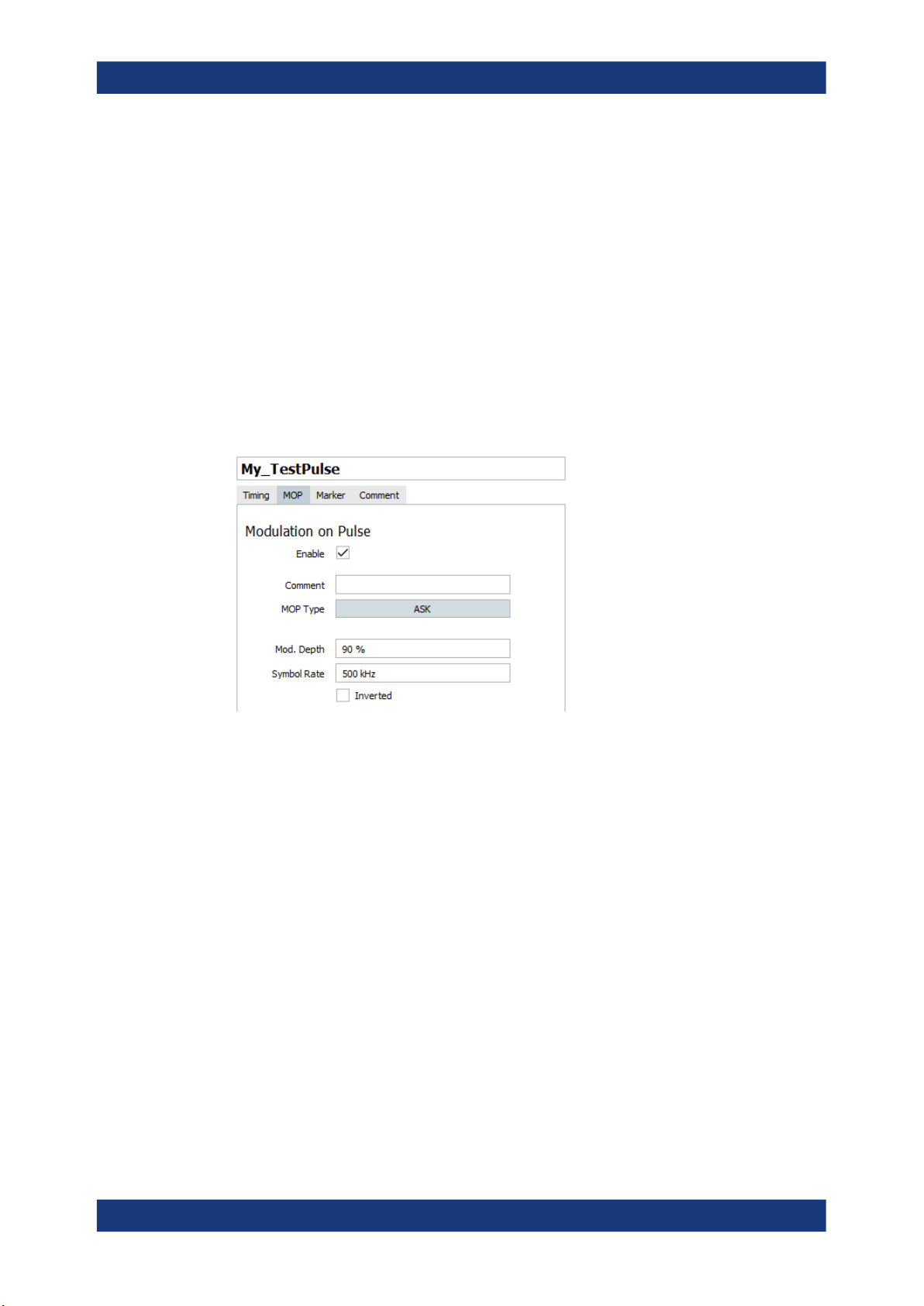
R&S®PULSE-K32/-K39
Remote command:
PULSe:MOP:AMSTep:ADD on page 420
PULSe:MOP:AMSTep:COUNt? on page 421
PULSe:MOP:AMSTep:SELect on page 421
PULSe:MOP:AMSTep:INSert on page 423
PULSe:MOP:AMSTep:LEVel on page 500
PULSe:MOP:AMSTep:DURation on page 500
PULSe:MOP:AMSTep:CLEar on page 424
PULSe:MOP:AMSTep:DELete on page 423
ASK
Enables an ASK where the amplitude of the RF carrier is attenuated for a symbol value
of zero and remains at full level for symbol values of one. The level of attenuation is
specified as depth in percent.
Creating a pulse library
Pulse settings
"Mod. Depth"
Depth of the modulation signal in percent.
m = (Amplitude
"Symbol Rate"
"Inverted"
Symbol rate of the modulating signal.
Inverts the amplitude-shift keying (ASK) modulation.
Meaning the RF carrier is attenuated for a symbol value of one.
Remote command:
PULSe:MOP:ASK:MDEPth on page 501
PULSe:MOP:ASK:INVert on page 500
PULSe:MOP:ASK:SRATe on page 501
6.2.3.3 FM and FSK modulation
The frequency modulation (FM) and frequency shift keying (FSK) modulation are modulation schemes that vary the frequency of the signal.
-Amplitude
max
) / (Amplitude
min
+Amplitude
max
min
)
95User Manual 1179.3873.02 ─ 03
Page 96

R&S®PULSE-K32/-K39
Settings:
FM.................................................................................................................................96
FM Step.........................................................................................................................96
FSK, 4FSK, 8FSK, 16FSK, 32FSK, 64FSK.................................................................. 97
MSK.............................................................................................................................. 98
FM
Enables an FM with a single tone.
Creating a pulse library
Pulse settings
"Frequency"
"Deviation"
Remote command:
PULSe:MOP:FM:FREQuency on page 506
PULSe:MOP:FM:DEViation on page 506
FM Step
The FM step modulation is a common pulse compression technique. It defines a modulation as a sequence of discrete states (table rows), each described with its "Duration"
and "Frequency".
Use the standard "Append", "Remove Last", or "Delete All" functions to add or remove
a row. The provided settings are self-explanatory.
Modulation frequency
FM frequency deviation
96User Manual 1179.3873.02 ─ 03
Page 97

R&S®PULSE-K32/-K39
Example: Sequence composed of four pulses with "MOP = FM Step"
●
Configure an FM step with f
= 5.
= -50 MHz, f
start
Creating a pulse library
Pulse settings
= 50 MHz, Step = 25 MHz, #Steps
end
●
Build a sequence and use the "Signal Preview" dialog to visualize the signal.
Remote command:
PULSe:MOP:FMSTep:ADD on page 420
PULSe:MOP:FMSTep:COUNt? on page 421
PULSe:MOP:FMSTep:SELect on page 421
PULSe:MOP:FMSTep:INSert on page 423
PULSe:MOP:FMSTep:FREQuency on page 500
PULSe:MOP:FMSTep:DURation on page 500
PULSe:MOP:FMSTep:CLEar on page 424
PULSe:MOP:FMSTep:DELete on page 423
FSK, 4FSK, 8FSK, 16FSK, 32FSK, 64FSK
Enables an FSK. High symbols set the frequency to "+Deviation" and low symbols to
"–Deviation".
97User Manual 1179.3873.02 ─ 03
Page 98

R&S®PULSE-K32/-K39
Creating a pulse library
Pulse settings
"Type"
"Symbol Rate"
"Deviation"
"Inverted"
Remote command:
PULSe:MOP:FSK:TYPE on page 504
PULSe:MOP:FSK:DEViation on page 506
PULSe:MOP:FSK:SRATe on page 507
PULSe:MOP:FSK:INVert on page 500
PULSe:MOP:4FSK:DEViation on page 506
PULSe:MOP:4FSK:SRATe on page 507
PULSe:MOP:8FSK:DEViation on page 506
PULSe:MOP:8FSK:SRATe on page 506
MSK
Enables an MSK.
Selects the FSK modulation type.
Symbol rate of the modulating signal.
FSK frequency deviation
Inverts the FSK modulation.
98User Manual 1179.3873.02 ─ 03
Page 99

R&S®PULSE-K32/-K39
Creating a pulse library
Pulse settings
"Symbol Rate"
"Inverted"
Remote command:
PULSe:MOP:MSK:SRATe on page 501
PULSe:MOP:MSK:INVert on page 500
6.2.3.4 Chirp modulation
A chirp is a signal in which the frequency varies over the time. The chirp sweeps the
RF signal across a set frequency range.
The chirp modulation scheme is used for pulse compression.
Settings:
Linear Chirp...................................................................................................................99
Piecewise Linear Chirp............................................................................................... 100
Custom Chirp.............................................................................................................. 101
Polynomial Chirp.........................................................................................................103
Linear Chirp
The linear chirp varies the frequency linearly over time.
Symbol rate of the modulating signal.
Inverts the MSK modulation.
99User Manual 1179.3873.02 ─ 03
Page 100

R&S®PULSE-K32/-K39
Creating a pulse library
Pulse settings
"Type"
"Deviation"
Defines the frequency variation:
●
Linearly increasing ("UPp")
●
Linearly decreasing ("Down")
●
Following a full sine wave ("Sine")
●
Ascending and then descending ("Triangular")
Chirp deviation.
The "Total Deviation" value updates automatically if you change the
"Deviation".
Remote command:
PULSe:MOP:CHIRp:TYPE on page 503
PULSe:MOP:CHIRp:DEViation on page 503
Piecewise Linear Chirp
Define the chirp as a sequence of chirp intervals with user-definable length and frequency deviation.
Figure 6-4: Piecewise Linear Chirp: understanding the displayed information
1 = Offset = 0 Hz; the start chirp frequency is 0 Hz
2, 3, 4 =
5 = In the remaining 34% of the chirp time, the frequency is kept constant
6 = Positive offset; the start chirp frequency in the second interval is 10 MHz
7 = Negative offset; the start chirp frequency in the third interval is -10 MHz
* = Theoretical example, in practice you rather vary the frequency during the whole time
Three chirp intervals with total duration of 66% of the whole time of which the MOP is applied
*)
100User Manual 1179.3873.02 ─ 03
 Loading...