

Page 1

Geschäftsbereich / Division
Überwachungs- und Ortungstechnik /
Radiomonitoring and Radiolocation
Operating Manual
PR/EM100 – Control for usage with
R&S PR100 and EM100
Printed in Germany
Page 2

PR/EM100 Control Contents
Contents
PR/EM100 – Control for usage with...................................................................................i
R&S PR100 and EM100 ....................................................................................................i
1 Introduction............................................................................................................................................3
1.1 General............................................................................................................................................3
1.2 Naming conventions ........................................................................................................................3
1.3 Copyright and Notices .....................................................................................................................3
1.4 About this Document .......................................................................................................................3
1.5 Related Documents .........................................................................................................................3
1.6 Disclaimer........................................................................................................................................3
2 Preparation for Use ...............................................................................................................................4
2.1 Prerequisites....................................................................................................................................4
2.2 Installing the Ethernet LAN Interface ..............................................................................................4
2.3 Installation of the PR/EM100 Control Software ...............................................................................4
3 Operating Instructions ..........................................................................................................................4
3.1 Introduction......................................................................................................................................4
3.2 Start-up............................................................................................................................................4
3.2.1 General....................................................................................................................................4
3.2.2 Enviroment requirements for the PR/EM100 client and server installation.............................4
3.2.3 Changing the Ethernet LAN settings.......................................................................................5
3.2.4 Changing the TCP/IP Host Address........................................................................................5
3.3 Closing the PR/EM100 GUI.............................................................................................................5
3.4 Application Window .........................................................................................................................5
3.5 Menu Bar .........................................................................................................................................7
3.5.1 File Menu.................................................................................................................................7
3.5.2 Control Menu...........................................................................................................................7
3.5.3 Configuration Menu .................................................................................................................8
3.5.4 View Menu.............................................................................................................................10
3.5.5 Extras Menu ..........................................................................................................................11
3.5.6 Help Menu .............................................................................................................................11
3.6 Toolbar ..........................................................................................................................................12
3.6.1 Main Toolbar .........................................................................................................................12
3.6.1.1 Frequency......................................................................................................................... 12
3.6.1.2 Frequency Store ............................................................................................................... 13
3.6.2 Demodulation Toolbar...........................................................................................................19
3.6.3 Audio Settings Toolbar..........................................................................................................20
3.6.4 PR/EM100 Modus Toolbar....................................................................................................21
3020.8306.02 i E-1.1
Page 3

PR/EM100 Control Contents
3.6.5 Tools Toolbar ........................................................................................................................25
3.6.6 Modus Editor Toolbar ............................................................................................................27
3.6.7 Internal Recording Toolbar....................................................................................................28
3.7 Displays .........................................................................................................................................29
3.7.1 RF-Spectrum Display ............................................................................................................30
3.7.1.1 Operations in the spectrum .............................................................................................. 33
3.7.2 RF-Waterfall Display .............................................................................................................43
3.7.2.1 Color Settings ................................................................................................................... 47
3.7.3 RF-Fast-Waterfall Display .....................................................................................................49
3.7.4 IF-Spectrum Display..............................................................................................................53
3.7.5 IF-Waterfall Display...............................................................................................................55
3.8 Status bar ......................................................................................................................................55
3.9 Create Reports (Option) ................................................................................................................55
3.10 Recording (Option) ......................................................................................................................55
3.11 IF-Recording (Option)..................................................................................................................56
3.12 Audio-Recording (not with firmware versions equal to or lower than 1.22) ................................56
3.13 Instant Replay..............................................................................................................................56
3.13.1 File Menu.............................................................................................................................57
3.13.2 Instant Replay Toolbar ........................................................................................................58
3.14 Function Keys/ Hot Keys .............................................................................................................59
4 Typical Operation ..................................................................................................................................60
4.1 General..........................................................................................................................................60
4.2 Monitor Single Frequencies...........................................................................................................60
4.3 Frequency Scan (not with firmware versions equal to or lower than 1.22) ...................................61
4.4 Search (not with firmware versions equal to or lower than 1.22) ..................................................62
4.5 MScan / MSearch (not with firmware versions equal to or lower than 1.22).................................62
4.6 Client Server Remote Control as Option (RA-RC) ........................................................................63
5 Appendix................................................................................................................................................64
5.1 Overview of the Antenna.txt file.....................................................................................................64
3020.8306.02 ii E-1.1
Page 4

PR/EM100 Control Operating Instructions
1 Introduction
1.1 General
This Manual refers to the Rohde & Schwarz receivers PR100 and EM100. The PR/EM100 Control
application is used to search and monitor different frequency ranges in the HF, VHF and UHF area. It
allows the operator to scan for multiple signals manually or automatically and to tune to signals for
detailed examination. Many types of radio signals can be handled by the configuration of a wide range
of signal parameters as well.
It is a PC-based measurement and monitoring system (stationary or mobile) software that allows
controlled operation of the device.
The PR/EM100 Control application supports two operational modes: The Fixed Frequency Mode FFM
and the SEARCH and SCAN Mode. The FFM mode is used to monitor radio communications on fixed
frequencies, while the SEARCH and SCAN mode is used to search/scan for communication channels in
a frequency range or to observe channels with known frequencies.
1.2 Naming conventions
The PR/EM100 Control application is a part of the ISAR – Framework. In this framework it can be used
to control the different monitoring receivers of the PR/EM100 family. These are: PR100 and EM100.
Therefore this manual refers to these R&S monitoring receivers and will be called PR/EM100 Control.
There are 2 possible ways to run the PR/EM100 Control. The PR/EM100 Control is especially designed
as the default and standard remote GUI for the receivers PR100 and EM100. In this case the
PR/EM100Box versions run without any connections to the Ramon system world.
The other possibility is to install the PR/EM100CTRL Control Software as a part of a complete Ramon
system. In this case there will be full connectivity to all the other Ramon components.
In both cases the GUI will have the standard Ramon look and feel.
1.3 Copyright and Notices
This document contains proprietary information to Rohde & Schwarz and shall not be used, disclosed
and/or duplicated, printed or copied except in accordance with express written authorization from
Rohde & Schwarz.
1.4 About this Document
This document is designed to describe how to use the PR/EM100 Control software. It does not describe
the PR/EM100 hardware nor describe how to operate in different search and monitoring scenarios. For
further descriptions see the related documents below.
1.5 Related Documents
Operating Manual – EM100 – HF/VHF/UHF Compact Receiver, Rohde & Schwarz
Operating Manual – PR100 – HF/VHF/UHF Compact Receiver, Rohde & Schwarz
1.6 Disclaimer
Every effort has been made by Rohde & Schwarz to make sure that the information contained within
this document is accurate and correct. However, slight differences may exist between the
documentation and particular installations.
3020.8306.02 3 E-1.1
Page 5

PR/EM100 Control Operating Instructions
2 Preparation for Use
2.1 Prerequisites
The Software ist designed to run on a PC under control of Microsoft Windows XP operating system.
The minimum hardware requirements for the PC are:
Processor 1.8 GHz
RAM 1024 MB
Harddisk > 1 GB free space
Graphics Adapter OpenGL1.2, 64 MB, 65536 colours, 1024 by 768 pixels
LAN adapter 100 Mbit/s, RJ-45 connector
Mouse
USB Adapter
TCP/IP
If you are running the PR/EM100 Control as part of the Ramon system and want to support a greater
number of concurrent applications and other devices (e.g two or more instances of PR/EM100
Control software, ReportEdit, Eval-Software, etc.) the processor and memory requirements should be
increased proportionately.
2.2 Installing the Ethernet LAN Interface
The PR/EM100 Receivers are controlled by an Ethernet LAN interface.
Please refer to the installation instructions of your Ethernet LAN interface.
2.3 Installation of the PR/EM100 Control Software
The PR/EM100 Control in the PR/EM100Box variant is installed as one Control application. An icon on
the desktop is generated, called PR100_1 or EM100_1. With this icon the software is started.
During the installation the TCP address of the PR/EM100 device must be configured for the application.
3 Operating Instructions
3.1 Introduction
The HF-VHF-UHF Compact Receivers of the PR/EM100 family can be controlled by means of the
Windows XP application PR/EM100 Control.
The following sections describe how to operate the PR/EM100 Control software.
For a quick start please refer to the chapter Typical Operation.
3.2 Start-up
3.2.1 General
Successful installation of the PR/EM100 Control software requires a basic understanding of PC and
network administration issues.
3.2.2 Enviroment requirements for the PR/EM100 client and server installation
1.) Please verify the following issues before starting the PR100/EM100 Control on the Server PC:
• An Ethernet LAN connection is established to the PR/EM100 device.
3020.8306.02 4 E-1.1
Page 6

PR/EM100 Control Operating Instructions
• The Ethernet LAN address and the Subnet Mask have to be set correctly.
There are two ways to start the PR/EM100 Control.
1st way:
Double-click the PR100_1 or EM100_1 icon on the desktop of the PC.
2nd way:
Click on the Start button, goto Programs – R&S Ramon – EM100 or PR100 and click on PR100_1 or
EM100_1.
Hint:
The name is equivalent to the selection during the installation procedure (Change GUI name).
3.2.3 Changing the Ethernet LAN settings
See the PR/EM100 Installation Manual for further information.
3.2.4 Changing the TCP/IP Host Address
There are two ways to change the connection of the PR/EM100CTRL in order to connect to a different
device or to adapt changes made on an existing device.
• In chapter 3.5.5 the Options dialog of the menu “Extras” is explained, that allows direct
changing of the TCP/IP Host Address of the PR/EM100 driver.
• A general way to change configuration entries like the host address via the CfgServer is
described in the RAMON Basic manual.
Changing the configuration via the CfgServer is only possible for the PR/EM100CTRL, not for the
Note:
PR/EM100Box version because it is installed without any RAMON Basic component.
3.3 Closing the PR/EM100 GUI
There are three ways to quit the PR/EM100 Control application:
• select the File Exit from the Menu Bar or
• by clicking the Alt+F4 key combination or
• by clicking the control menu box and close the application as known from standard Windows
usage.
3.4 Application Window
On startup of the PR/EM100 control application following default application window is displayed.
3020.8306.02 5 E-1.1
Page 7

PR/EM100 Control Operating Instructions
Title Bar
Title Bar
Menu Bar
Menu Bar
Main Toolbar
Main Toolbar
Standard Toolbar
Standard Toolbar
Modus EditorToolbar
Modus EditorToolbar
IF Waterfall Display
IF Waterfall Display
IF Spectrum Display
IF Spectrum Display
RF Spectrum Display
RF Spectrum Display
Status Bar
Status Bar
Title bar:
In the Title bar the name of the PR/EM100 Control application is displayed. It also offers a button for
closing and resizing the PR/EM100 Control.
Menu Bar:
With the Main Menu bar the operator is able to control the PR/EM100 and to adjust view of the
PR/EM100 Control. For further information please refer to the chapter Main Menu.
Toolbar:
With the Toolbar the operator is able to control the most important functions of the PR/EM100. For
further information please refer to the chapter Toolbar.
Spectrum and waterfall displays:
• 2D IF spectrum and waterfall display: This display is only available in FFM, Search and
MSearch mode. It is activated by pressing the Toggle Views (F9) button.
• RF spectrum and waterfall display: This display is available in all operating modes.
Note: The RF waterfall display is activated by pressing the Toggle Views (F9) button.
The size of the spectrum displays can be changed by clicking with the left mouse button on the line
separating the spectrum windows and dragging the line.
For further information please refer to the chapter Displays.
Status bar:
The status bar displays information about the mode of operation.
For further information please refer to the chapter Displays.
3020.8306.02 6 E-1.1
Page 8

PR/EM100 Control Operating Instructions
3.5 Menu Bar
The Menu Bar consists of the following menus:
• File
• Control
• Configuration
• View
• Extras
• Help
The menu items may be selected via the mouse button or by pressing the Alt key and entering the
underlined character of the menu name.
3.5.1 File Menu
Exit
Closes the PR/EM100 Control.
3.5.2 Control Menu
Menu Control allows to control the operation modes of the PR/EM100.
Stop
PR/EM100 stops any search, scan and ffm activity and switches into silent mode, no traffic will be
on the network. The communication to the device will be suspended.
Fixed Frequency Mode
PR/EM100 stops any search or scan operation in order to monitor a single frequency given in the
frequency edit field.
Panorama Scan
PR/EM100 starts a scan of the frequency range defined in the Scan / Search section of the
toolbar. The frequency step can be set to predefined discrete values of 3.125 kHz, 6.25 kHz, 12.5
kHz, 25 kHz, 50 kHz and 100 kHz.
See section 4.3 Frequency Scan for more information.
Note: This mode is only available if the device is equipped with the option “PS”
(not available with firmware version equal to or lower than 1.22)
Scan
3020.8306.02 7 E-1.1
Page 9

PR/EM100 Control Operating Instructions
PR/EM100 starts a scan of the frequency range defined in the Scan / Search section of the
odus editor toolbar. No hold and dwell time will be considered. The RF spectrum and waterfall
m
views will be displayed.
Search
(not available with firmware version equal to or lower than 1.22)
Searches the frequency range that is defined in the Scan / Search section of the toolbar for active
signals (signal level above threshold).
MScan
(not available with firmware version equal to or lower than 1.22)
Switches to memory scan.
MSearch
(not available with firmware version equal to or lower than 1.22)
Searches the frequency list that is defined in the frequency store for active signals (signal level
above threshold). The frequency store can be filled e.g. with the menu/toolbar <add frequency>
item.
Reset PR/EM100
Reset the PR/EM100 device.
Download File from Receiver
Download a file from the internal filesystem of the receiver. This is only possible for small files
<2MB, larger files can cause the control software to freeze.
3.5.3 Configuration Menu
Configure Colos
A dialog for the color configuration of the Application will be displayed.
Receiver Configuration
A dialog for the receiver configuration will be displayed.
Please refer the PR/EM100 manual for further information.
3020.8306.02 8 E-1.1
Page 10

PR/EM100 Control Operating Instructions
Data Stream Configuration
A dialog for the data stream configuration will be displayed.
Please refer to the PR/EM100 manual for further information.
Speaker Configuration
A dialog for the speaker configuration will be displayed. The operator can select the sample
rate/Bit per Sample/Channels value for the audio output. Due to a nonexisting integrated speaker
at the PR/EM100 receiver, only the Soundcard Output option is available.
3020.8306.02 9 E-1.1
Page 11

PR/EM100 Control Operating Instructions
3.5.4 View Menu
New RF-Spectrum
Opens a new RF spectrum window.
Big Level Display
Hides the normal level measurement widget and shows the current Level in big digits.
Reset View to Factory Default
Resets the application layout to the factory default
Reset View to Program Start
Resets the application layout to the program start
Toolbars
Shows or hides the selected toolbar
3020.8306.02 10 E-1.1
Page 12

PR/EM100 Control Operating Instructions
3.5.5 Extras Menu
Reset user colors
Reset all user defined colors to the default values.
Configure colors
Opens a dialog to manually configure the colors used in this application.
Options
The option menu opens a window with information about the GUI and the configuration options of
the GUI Software. The following window is opened after choosing “Options”
By selecting the “Configuration” tab an overview of possible configuration attributes is displayed. With
this dialog e.g. the TCP/IP Host address of the PR/EM100CTRL can be changed.
3.5.6 Help Menu
Contents
This menu opens the online help, by starting a PDF viewer with this user manual file.
Keyboard
3020.8306.02 11 E-1.1
Page 13

PR/EM100 Control Operating Instructions
Open History List
Open Frequency Store
Comment for current
e via
: While
comment
Click here to set the last
Modify the current frequency
using the spin buttons or by
keys (up / down).
Select a decimal place of the
Displays the available Hotkeys. See chapter 3.13 for more Information
Info
Opens a window with information about the software version, modules, configuration options and
the firmware of the connected device.
3.6 Toolbar
The toolbar of the application contains buttons for the most commonly used items. When a button on
the toolbar is clicked the action of the corresponding menu item is performed immediately.
Main Toolbar
Main Toolbar
Standard Toolbar
Standard Toolbar
Modus EditorToolbar
Modus EditorToolbar
The toolbar of the application consists of three sections:
• Main Toolbar
• Standard Receiver Toolbar
• Modus Editor Toolbar.
All toolbars can be hidden or displayed in the View menu. These settings are remembered after a
restart of the software.
3.6.1 Main Toolbar
The Main toolbar contains buttons and displays to operate the PR/EM100 in Fixed Frequency Mode
(FFM).
3.6.1.1 Frequency
using arrow-
frequency to get faster result
frequency if availabl
Frequency Store
in bandwidth,
displays bold
frequency
The Frequency may be changed by
• Press the F6 shortcut key. This sets the focus to the frequency display.
• Double click the frequency display and enter the frequency value directly.
If the operator enters only the frequency (without unit), the frequency is set with the same unit as it
was set before. The unit of the frequency can be changed by entering the first letter of the unit after
the number (for example: 98.5m for 98.5 MHz, or 98500k for 98500 kHz)
3020.8306.02 12 E-1.1
Page 14

PR/EM100 Control Operating Instructions
The operator has to press the Enter key or click to another element of the window to accept the
requency.
f
• Set the cursor on the digit of the frequency display that has to be changed. Using the Up or Down
arrow keys of the keyboard or clicking on the Up / Down spin buttons changes the frequency.
• Set the suffix for the whole application by pressing “m”-key for MHz, “k”-key for kHz or “g”-key for
GHz. Frequency axis will use this suffix.
• Open the Frequency Store and the Frequency History List:
• The Frequency Store contains a list of frequencies. Click on the arrow to open the Frequency
Store. Selecting a frequency from the frequency store sets this frequency and its stored
parameters (bandwidth etc.). The Frequency Store is saved between sessions.
• The Frequency History contains a temporary history of all frequencies entered manually in the
frequency field. It can also be used to set the frequency by clicking on the arrow and selecting a
frequency. The Frequency History is not stored between sessions.
Clicking on the Tune button .
The frequency is tuned to the peak signal level.
Value range of Frequency is depending on the device.
3.6.1.2 Frequency Store
Frequency Store may be opened from the Frequency Control or from the Frequency Bar.
The frequency window may be switched between 2 views: small (selection) and wide (editing). The
small view is used to select a frequency to be tuned. The view closes when a frequency has been
selected out of the list. The small view has no buttons except “Wide” and “Always on top”.
3020.8306.02 13 E-1.1
Page 15

PR/EM100 Control Operating Instructions
Keep window on top.
Window stays on top.
, Make window small / wide.
Once in wide view, select a tab to display one of the lists:
Notepad
Entries of frequency store lists are displayed as well above frequency axis of RF Controls. Each list
uses its own symbol and colors for its entries in the list and the frequency bar (the bar above the
frequency axis)
Wide view is used to edit the frequency lists:
Lists may be edited (or not), available for e.g. notepad frequencies are:
Add a new item to the list
Edit selected item
Delete selected item(s)
Open file
Merge file: load a other file into the list - keep the currently loaded items.
Save items to a list. Once a list is opened and a filename is known to the frequency store
(filename will be displayed in the caption) the file will be saved automatically during shutdown of
the program.
3020.8306.02 14 E-1.1
Page 16

PR/EM100 Control Operating Instructions
Copy item: it may be basted to a other list in the frequency store.
aste item.
P
Lists available:
Notepad: user defined frequencies (frequency, bandwidth, demodulation, comment) displayed
in the frequency bar in spectrum and IF spectrum display.
Recycle Bin: Deleted entries from frequency lists in the store end up here and may be restored
from here.
Global (set from other applications e.g. Rohde & Schwarz AMMOS) suppress frequencies and
ranges.
Local (set by job editor or in spectrum display) suppress frequencies and ranges.
Recycle Bin
Whenever a entry of one of the lists is deleted, it will be displayed here in the recycle bin. You may
restore an entry to its origin or erase it finally. Recycle bin entries are only available during
program live time. Once the program is closed, all entries are gone.
3020.8306.02 15 E-1.1
Page 17

PR/EM100 Control Operating Instructions
Suppress Ranges
There are local and global suppress ranges, local are displayed in yellow, global are displayed in red.
Frequency ranges stored in these lists will not be scanned or searched during scan or search
The global suppress ranges are defined by a supervisor and can then be distributed over the whole
system by him. They are shown as a red bar in the frequency bar and a darkgray block in the spectrum.
The local suppress ranges are only focused on the local device and can be defined by the operator
itself. These are shown in yellow.
Editing of suppress ranges list is similar to editing notepad frequencies, except there is a start and stop
frequency instead a frequency and its bandwidth.
Edit Modes:
Add a new range to the list
Edit selected range
Delete selected range – deleted ranges are displayed in the recycle bin as a corresponding
frequency / bandwidth pair and may be restored from there.
Open file
Merge file: load a other file into the list - keep the currently loaded ranges.
Save ranges to a list. Once a list is opened and a filename is known to the frequency store
(filename will be displayed in the caption) the file will be saved automatically during shutdown of
the program.
Copy range: it may be basted to a other list in the frequency store.
Paste range.
Note: These edit functionality is only available for local suppress ranges, or for global suppress ranges
if you are the supervisor.
3020.8306.02 16 E-1.1
Page 18

PR/EM100 Control Operating Instructions
• The added frequencies of the Memory Items list will be of interest when applying MScan or
MSearch.
Clicking on the New symbol creates a new item. A short edit dialog will appear, where
parameters of the item can be edited. The dialog’s options Frequency, Demodulation, Bandwith
etc. will be initialized with the current settings from the Main Application window.
• The comment can be used to identify the frequency with an alias name, which will be
automatically displayed in the spectrum. Other static values (e.g. attenuation, squelch, afc,
antenna) for this single frequency item can be edited. Frequency items can be activated by
checking the Active box. Only the active items will be scanned/searched during MScan or
MSearch.
Clicking on the Edit symbol opens the edit dialog, where previously defindes frequencies can
be edited the same way mentioned above.
Clicking the Delete symbol deletes the selected item(s).
Clicking on the File Open symbol will open a file open dialog to select a valid sfl file to load all
items in the file in the current frequency store. Previously defined frequencies are discarded.
Clicking on the File Merge symbol will open a file open dialog to select a valid sfl file to merge
all items in the file with the current frequency store.
Clicking on the File Save As symbol will open a file save as dialog to save all items in the
current list into a sfl file.
3020.8306.02 17 E-1.1
Page 19
PR/EM100 Control Operating Instructions
Clicking on the Import symbol will import frequencies from the Frequency Store of the
connected device.
Clicking on the Export symbol will export frequencies from the GUI’s Frequency Store to the
connected device.
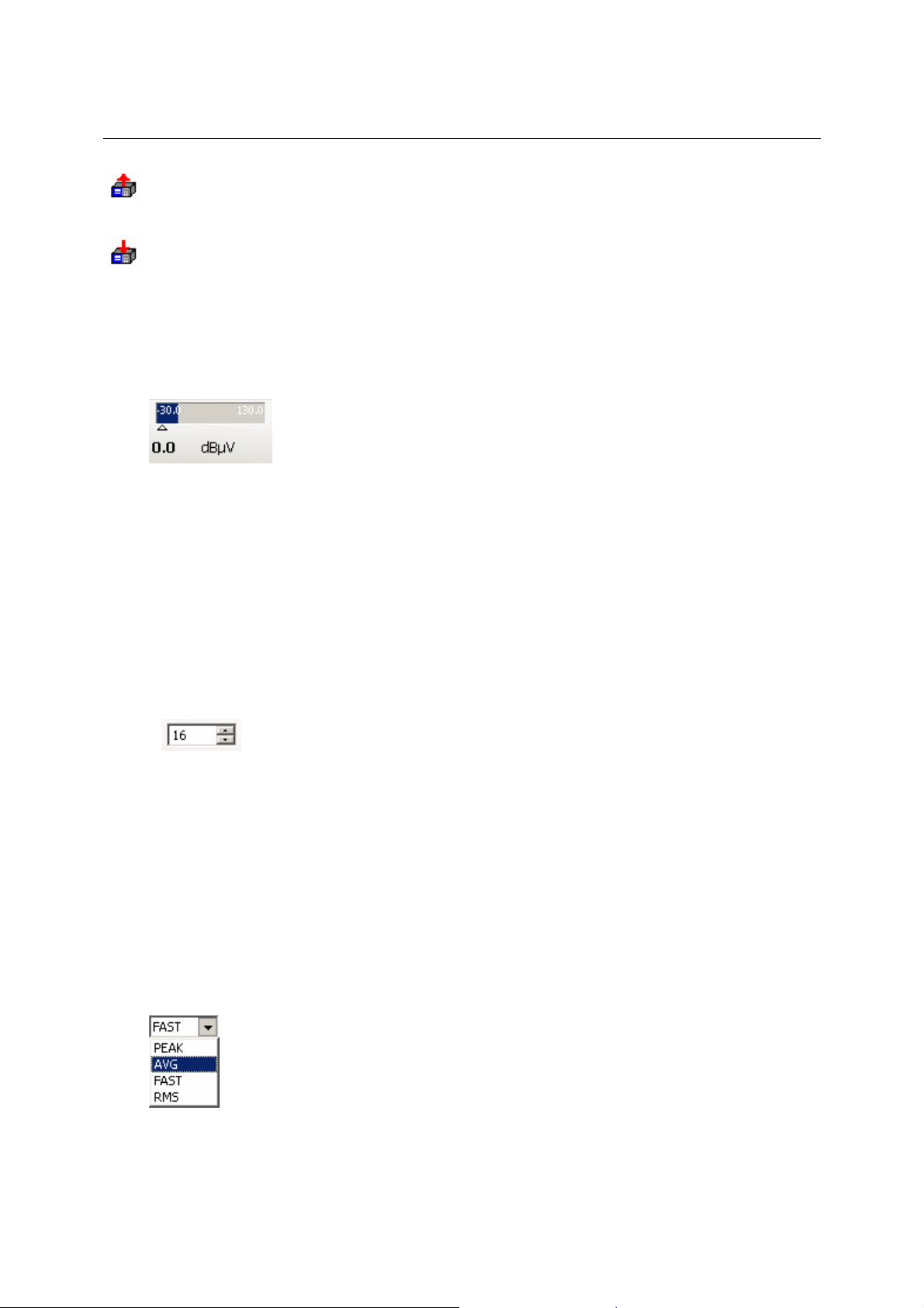
Level Display
(not with firmware versions lower or equal to 1.22)
The Level Display contains the following information:
• current value of the RF signal level as level indicator.
• current value of the RF signal level as numerical value.
• Maximum value of the RF-level of the selected frequency as level indicator (right
blue line).
• Possible range of level: -30 dBOV to 110 dBOV
Threshold / Squelch
The threshold for search and the squelch for audio may be set by
• double-clicking the threshold / squelch display and entering the threshold / squelch
value directly.
• clicking on the Up or Down spin buttons of the threshold / squelch display.
• moving the threshold / squelch ruler in the RF-spectrum display.
Value range: -30 dBOV to 130 dBOV
Level Indication
Set the level indication to PEAK, AVG, FAST or RMS.
Offset Display
(not with firmware versions lower or equal to 1.22)
3020.8306.02 18 E-1.1
Page 20

PR/EM100 Control Operating Instructions
The frequency offset is presented as a numerical display as well as in the form of a tuning meter.
he display depends on the selected bandwidth and can only be used for qualitative
T
assessments.
AFC
Automatic frequency control (AFC) may be switched on and off by clicking on the AFC button.
3.6.2 Demodulation Toolbar
This Toolbar consists of the following elements:
Demodulation
Select the demodulation mode.
Values: depending on the device
IF Bandwidth
Attenuation
Select the IF bandwidth.
Values: depending on the device.
The Attenuation can be switched off, set to 30 dB or set to automatic function by clicking on
the Attenuation button
The LED on the Attenuation button changes the color:
•
•
•
gray: Attenuation switched off
green: Attenuation 30 dB
light green: automatic attenuation
3020.8306.02 19 E-1.1
Page 21

PR/EM100 Control Operating Instructions
Gain Control
By clicking on the AGC button gain control can be switched on
If gain control is switched off
• double-clicking the MGC level display and entering the MGC level value directly.
• clicking on the Up or Down spin buttons.
MGC value range: -30 to +130
MGC mode is active. The MGC level can be set by
or off.
3.6.3 Audio Settings Toolbar
There are two display modes for the Audio Settings: one using spin boxes for displaying Channel
Volume, Master Volume, Channel Panorama and Squelch and distinguished buttons for Channel
Mute, Master Mute and Squelch; the other uses so-called “Compact Controls” for seldom
changed values, i.e. Channel Volume and Mute, Master Volume and Mute and Channel
Panorama. A click on one of the “Compact Controls” opens a drop-down menu where you can
set the audio parameters. The Squelch value spin box and on/off toggle button are shown at all
times.
• Audio Settings with standard controls
Channel
Volume and
Mute
Squelch
Display
Options
Master Volume
and Mute
Use the toggle button to enable or disable the respective feature (sound output, squelch) and use
the spin box to select the corresponding parameter value (volume level, squelch level, panorama
value).
• Audio Settings with Compact Controls
Channel
Volume and
Mute
Master Volume
and Mute
A click on a Compact Control button opens a drop-down menu, where you can change the
respective value by using a slide bar.
Squelch
Channel
panorama
Channel
Panorama
Display
Options
3020.8306.02 20 E-1.1
Page 22

PR/EM100 Control Operating Instructions
The volume controls provide a checkbox for muting audio output. When muted, the green bar
elow the speaker symbol will change to grey.
b
The panorama control features a “Center” button which will reset the panorama setting to zero.
• Display Options Button
A click on the Display Option Button opens the following drop-down menu:
In this menu you can toggle the visibility of all available controls. Deselecting an entry hides the
respective controls.
The last entry allows you to switch between standard controls and “Compact Controls” as
described above.
3.6.4 PR/EM100 Modus Toolbar
The PR/EM100 Modus toolbar contains important buttons to control the PR/EM100.
Channel Navigation
The operator can tune the frequency by clicking on the arrow buttons
. By clicking on the left button the frequency is
decreased, by clicking on the left button the frequency is increased by one channel.
3020.8306.02 21 E-1.1
Page 23
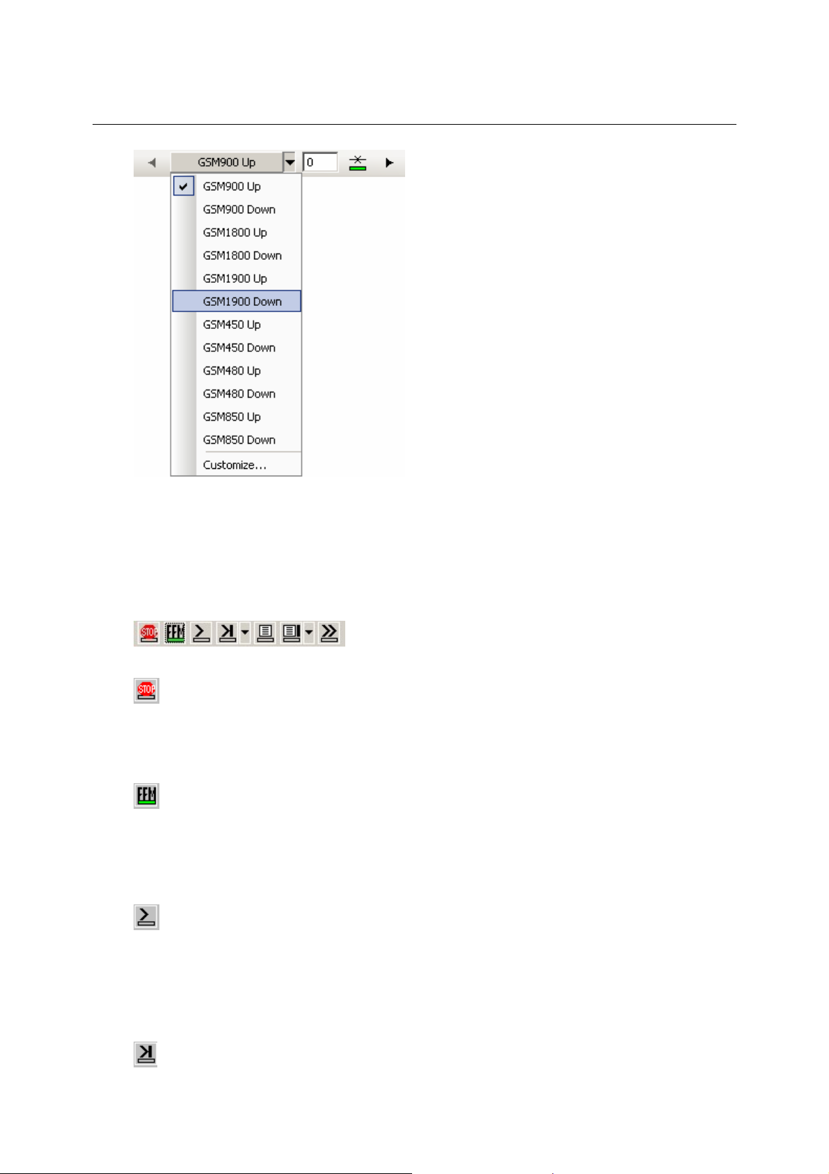
PR/EM100 Control Operating Instructions
Here the operator can select the service and step through the channels of this service.
The operator may specify its own services by clicking on the customize button. These can also
be saved and loaded here.
Mode of operation
The operator can select between six modes of the PR/EM100 by clicking left mouse on the
corresponding button.
Stop
Click on the Stop button to stop scanning, searching or ffm polling to switch into silent mode. The
displays in the GUI will be frozen and the communication between the EMx50 driver application
and the device will be suspended until another mode is selected.
Fixed Frequency
Click on the FFM button to stop scanning or searching, in order to switch to Fixed Frequency
mode and to monitor a single frequency.
The FFM button corresponds to the function key F2.
(Frequency) Scan
(not in firmware versions lower or equal to 1.22)
Click on the Scan button to start a scan according to the settings defined in the Modus Editor
toolbar. The threshold for the scan is set in the level section of the toolbar or by moving the ruler
of the RF-spectrum display. The PR/EM100 scans the selected frequency range and the
associated RF-spectrum is displayed where the operator may examine the signal activities.
Pressing the function key Shift+F4 may also start a scan.
(Frequency) Search
(not in firmware versions lower or equal to 1.22)
The Search button is used to start searching the selected frequency range for active signals.
3020.8306.02 22 E-1.1
Page 24

PR/EM100 Control Operating Instructions
requency range, stepwidth are defined in the Modus Editor toolbar. The threshold for searching
F
is set in the level control of the toolbar or by moving the threshold ruler in the RF-spectrum
display.
The PR/EM100 scans the frequency range of interest; the associated RF-spectrum is displayed.
If there is a frequency with signal level over threshold, the PR/EM100 remains at this frequency
for the dwell time. The frequency marker jumps to the detected frequency and the frequency is
isplayed in the frequency edit field.
d
The Search button corresponds to the function key F3.
Switching between Search and Hold State (in dwell time) will be indicated by the LED sign in the
Search button. A red color indicates the Hold state, while a green color indicates the Search
state.
(Frequency) Search Menu
(not in firmware versions lower or equal to 1.22)
The Search Popup Menu button is used to control and edit searching.
- FFM: switch back to FFM mode at current frequency
- Continue Search: continue search in dwell time, start after current frequency
- Restart Search: start search from the beginning
- Suppress and Continue: suppress current frequency and continue search
- Configure Search: open the configure search dialog
Search Configuration Dialog
(not in firmware versions lower or equal to 1.22)
In the search configuration dialog the user can specify attributes for search criteria like dwell time
and hold time. The PR/EM100 will stop for the defined dwell time if a frequency above the
threshold was detected.
Values: depending on the device .
Memory Scan (MSCAN)
(not in firmware versions lower or equal to 1.22)
Click on the MScan button to start a memory scan according to the settings defined in the
frequency store list. The frequency store can be filled with the menu/toolbar <add frequency to
3020.8306.02 23 E-1.1
Page 25

PR/EM100 Control Operating Instructions
memory item list> item. Before starting an MSCAN, the frequencies were stored into the device
utomatically.
a
The threshold for the scan is set in the level section of the toolbar or by moving the ruler of the
RF-spectrum display. The PR/EM100 scans the current frequency list and the associated RFspectrum is displayed where the operator may examine the signal activities.
Memory Search (MSEARCH) (not in firmware versions lower or equal to 1.22)
The MSearch button is used to start searching the frequency list for active signals. The frequency
store can be filled with the menu/toolbar <add frequency to memory item list> item. Before
starting an MSEARCH, the frequencies were stored into the device automatically.
The threshold for searching is set in the level control of the toolbar or by moving the threshold
ruler in the RF-spectrum display.
The PR/EM100 searches the frequency list of interest; the associated RF-spectrum is displayed.
If there is a frequency with signal level over threshold, the PR/EM100 remains at this frequency
for the dwell time. The frequency marker jumps to the detected frequency and the frequency is
displayed in the frequency edit field.
Note:
If a single threshold is set for each frequency in the frequency list, this threshold will be used
instead of the common threshold.
Memory Search Menu
(not in firmware versions lower or equal to 1.22)
The Memory Search Popup Menu button is used to control and edit memory searching.
- FFM: switch back to FFM mode at current frequency
- Continue MSearch: continue msearch in dwell time, start after current frequency
- Restart MSearch: start memory search from the beginning of the frequency list
- Suppress and Continue: suppress current frequency and continue search
- Configure MSearch: open the configure memory search dialog
Memory Search Configuration Dialog
(not in firmware versions lower or equal to 1.22)
3020.8306.02 24 E-1.1
Page 26

PR/EM100 Control Operating Instructions
n the memory search configuration dialog the user can specify attributes for memory search
I
criteria like dwell time, hold time and squelch from memory slot enable. The PR/EM100 will stop
for the defined dwell time if a frequency above the threshold was detected.
The Values depend on the device.
Panorama Scan (PSCAN)
Note: This mode is available only if the device option “PS” is installed!
Click on the PSCAN button to start scanning according to the settings defined in the Modus
Editor toolbar. The threshold for the scan is set in the level section of the toolbar or by moving the
ruler of the RF-spectrum display. The operator obtains a fast overview of the signal activities in a
selected frequency range. The PR/EM100 scans the selected frequency range and the
associated RF-spectrum is displayed.
The PSCAN button corresponds to the function key F4.
See section 4.3 Frequency Scan for more informations.
3.6.5 Tools Toolbar
This toolbar provides some helpful tools.
Logging (Option)
Click with the left mouse button on the Logging button to start logging. The Logger application
must be started to activate this function. See the Logger manual for further details.
Note: The logger application is delivered with the RAMON Basic Software.
Click with the left mouse button on the Logging Popup button
menu to enable/disable logging and to set the logging interval.
The following menu functions are available:
- Menu Off switches logging off
- Menu On switches logging on
- Menu Logger Setting... popups the logging Settings Dialogue:
to show the logging popup
Enter the desired time in milliseconds and enable/disable a trigger functionality. The logging data
are sent to the logger application according to the defined interval.
3020.8306.02 25 E-1.1
Page 27

PR/EM100 Control Operating Instructions
Recording (Option)
Click with the left mouse button on the Recording button to start recording.
See chapter 3.10 for further details.
IF-Recording (Option)
Click with the left mouse button on the IF-Recording button to start the IF-Recording. This is only
available in FFM mode.
See chapter 3.11 for further details.
Audio Recording
Clicking on this button will start to record the received audio. The files will be stored in the
standard recording directory.
Reporting (Option)
On left mouse click on the Report button, a set of the current settings and results of the EMx50 frequency, level, offset, bandwidth and antenna name - is sent to the Report application. Use this
function to report results. Please refer to the User Manual of the Report Application for detailed
information about the Report Application.
See chapter 3.9 and the ReportEdit manual for further details.
The Report button corresponds to the function key Shift+F10.
Add Frequency to Notepad
Click with the left mouse button on the Add Frequency to notepad button to add the marked
frequency in the RF/IF-display into the Frequency Store Notepad section.
The Add Frequency to Notepad button corresponds to the function key Shift+F9.
Add Frequency to Memory Item List
Click with the left mouse button on the Add Frequency to Memory Item List button to add the
marked frequency in the RF/IF-display into the Frequency Store Memory Items section. All
frequencies in the store can be exported to the device to set these frequencies for the memory
scan.
See chapter Known Frequency List and MSCAN / MSEARCH for further details.
Suppress Frequency
Click with the left mouse button on the Suppress Frequency button to add the marked frequency
in the RF/IF-display into the Global/Local Suppress Channels section of the Frequency Store. All
frequencies in the store can be exported to the device to set these frequencies for the memory
scan. Those frequencies will not be scanned or searched.
See chapter Known Frequency List and MSCAN / MSEARCH for further details.
3020.8306.02 26 E-1.1
Page 28

PR/EM100 Control Operating Instructions
Toggle Display Views
Click with the left mouse button on the Toggle Views button to show different display views.
1. show IF spectrum with IF waterfall and RF spectrum
2. show IF spectrum and IF waterfall, VD spectrum and VD waterfall and RF spectrum
3. show IF spectrum with IF waterfall
4. show VD spectrum with VD waterfall
5. show RF spectrum with RF waterfall
The Toggle Views button corresponds to the function key F9.
Click with the left mouse button on the Toggle Views Popup button
views popup menu.
The following menu functions are available:
- Menu show IF spectrum with IF waterfall and RF spectrum
- Menu show IF spectrum and IF waterfall, VD spectrum and VD waterfall and RF spectrum
- Menu show IF spectrum with IF waterfall
- Menu show VD spectrum with VD waterfall
- Menu show RF spectrum with RF waterfall
Note: The button is only available in FFM and Search/MSearch Mode
Instant Replay
Click with the left mouse button on the Instant Replay button to open the instant replay window.
See chapter 3.12 for further details.
The Instant Replay button corresponds to the function key Ctrl+F9.
to show the toggle
3.6.6 Modus Editor Toolbar
In the Modus Editor Toolbar the settings for the Search, Scan and Panorama Scan of the PR/EM100
can be defined.
Modus Box
The modus box indicates the actual mode of the.receiver.
Dispayed Modes: FFM, SCAN, SEARCH, MSCAN, MSEARCH, PSCAN
Define the Scan/Search parameters
3020.8306.02 27 E-1.1
Page 29

PR/EM100 Control Operating Instructions
efine the start frequency, stop frequency and stepwidth for a scan or search run.
D
This settings can not be changed during scan or search mode.
In PSCAN mode of operation only discrete step values of 3.125 kHz, 6.25 kHz, 12.5 kHz, 25 kHz,
50 kHz und 100 kHz can be selected. Other step values will be changed to the next possible
value automaticly.
3.6.7 Internal Recording Toolbar
(only with firmware option “Internal Recording” and not in firmware version equal to or below 1.22)
With the firmware option “Internal Recording” the PR/EM100 is able to record different data sources to
the internal memory or the internal SD-Card. If this firmware option is detected by the control software,
a toolbar with the necessary controls will be displayed. The appearance depends on which recording
mode is selected.
SD-Card Mode:
Figure 3-1 Internal Recording in SD-Card-Mode
In this mode all the recorded data will be saved into files on the internal SD-Card. The second dropdown box selects which data will be recorded. It is possible to choose between Audio, AOS (Audio on
squelch, Traces and IQ Data. The names of the files will be set according to which data source is
chosen. The red recording button starts to record until the black stop button is pressed. It is then
possible to download the file either via the Control Software (for small files < 2MB) or to copy them
directly from the SD-Card.
Memory Mode:
Figure 3-2 Internal Recording in Memory-Mode
When selecting the device memory as the recording target there are two more options. The first one
defines the maximum size of the recording in the memory and the second one switches the recording
from cyclic mode to one-time-recording. In cyclic mode the recording will continue until the stop button
is pressed but only keep the last few minutes (depending on the datarate of the recording) in memory.
In one-time-recording mode the recording will finish after the amount of memory (8MB, 16MB, 32MB or
64MB) is reached.
3020.8306.02 28 E-1.1
Page 30

PR/EM100 Control Operating Instructions
3.7 Displays
The PR/EM100 Control application offers the following displays:
• RF-spectrum display
• RF-waterfall display
• RF-fast-waterfall display
• IF-spectrum display
• IF-waterfall display
3020.8306.02 29 E-1.1
Page 31

PR/EM100 Control Operating Instructions
Level axis
Caption: width of the spectrum
Current resolution
Frequency Axis
Current threshold
3.7.1 RF-Spectrum Display
In the spectrum window the user may
• monitor the spectrum of a frequency range during scan or search.
• set the yellow vertical frequency ruler (which also sets the reference frequency).
• examine the result panel which displays the reference frequency and the level.
• take measurements of signals with vertical and horizontal rulers.
• zoom-in for a higher frequency/channel resolution.
• set the threshold by dragging the white threshold ruler.
• set the minimum and the maximum value of the RF-level axis.
• select the colors of the RF-waterfall display.
Display modes
Draw modes may be selected via
• Right click the spectrum
• In the context menu, select “Properties”
• In the property page, select the display mode:
Comb:
3020.8306.02 30 E-1.1
Page 32

PR/EM100 Control Operating Instructions
Line:
Line has more options,
• Step, which will show a stepfunction, each step in the width of the current step width of the scan
/ search.
• Fill will fill the screen up to the measured line using the curves color.
3020.8306.02 31 E-1.1
Page 33

PR/EM100 Control Operating Instructions
Short overview of draw modes:
Line Line + Fill Line + Step Line + Step + Fill Comb
• Line draws a line from one measured point to the next, if one point is missing e.g. because this
point is below the current set threshold, there is a gap in the curve.
• Line and Step uses the current defined step width of the scan to draw a horizontal line. If P(x, y)
defines the point and step defines the step width, the line is drawn from P(x – step/2, y), to P(x
+ step/2, y). All horizontal lines are connected by vertical lines.
• Comb mode draws just one line per measured point. If P(x, y) defines the point, the line is
drawn from P(x, y), to P(x, 0).
• If there are as many measured points as pixels in x-direction or more available, Comb, Line +
Fill and Line + Fill + Step look the same.
• If this case, (more channels than pixels), only the channel with the highest level will be drawn.
• If performance is important, select Line + Step, this is supported best by the hardware of your
computer. – This is the fastest mode.
Performance
There is a option called Enable Fast Mode. In this mode,
• Min Max Hold is disabled
• Draw mode is set to Line + Step
• Ruler and Result Panels will be hidden.
3020.8306.02 32 E-1.1
Page 34

PR/EM100 Control Operating Instructions
Min/Max Hold
• Max Hold may be enabled by selecting a hold time in the combobox.
• If Max Hold is enabled, Min Hold may be enabled as well.
• Min and Max Values are displayed as single Dots, a connected line, or shadow:
Min Max Hold, using Shadow mode:
3.7.1.1 Operations in the spectrum
In the following the operations available in the RF-spectrum are described in detail.
Set the frequency ruler:
• Select an interesting signal in the RF-spectrum display.
• Click into the RF-spectrum display with the left mouse button in order to set the yellow vertical
frequency ruler.
• The reference frequency is displayed in the yellow frequency label at the lower end of the
frequency ruler as well as in the main frequency edit field (FFM-frequency) of the toolbar.
• The yellow triangle of the frequency ruler is set to the level of the frequency. If the triangle is at
the bottom of the RF-spectrum, this indicates that there is no level found for the current
frequency.
• Notice: while you selected “Enable Fast Mode” in the spectrums properties, no rulers or
markers are shown.
Move the frequency ruler:
• Move the mouse pointer to the frequency ruler; the pointer changes to .
• Click the left mouse button, keep it pressed and drag the ruler.
• Release the mouse button.
• The reference frequency is set according to the selected position in the RF-spectrum.
3020.8306.02 33 E-1.1
Page 35

PR/EM100 Control Operating Instructions
• The frequency ruler can also be moved by dragging the yellow label of the frequency ruler with
the left mouse button.
Set the reference frequency ruler next pixel or channel using keyboard:
• To enable this function, make sure, the spectrum widget got the input focus. If so, the caption is
displayed in your windows caption color – often blue. If not, set the focus by clicking into the
window or it’s caption.
• Use the left / right arrow keys of the keyboard to set the yellow reference frequency ruler to the
next / last pixel or channel with a value above threshold.
• If there are as many measured points as pixels in x-direction or more available, the ruler is
moved to the next pixel, otherwise to the next channel.
Set the reference frequency ruler to next local maximum
• To enable this function, make sure, the spectrum widget got the input focus. (see above)
• Use the up / down arrow keys of the keyboard to set the yellow reference frequency ruler to the
next / last active signal with a local maximum level above threshold.
Toggle the result panel for the frequency ruler:
• Set the frequency ruler.
• Pressing the Space tab toggles the result panel on and off.
In the result panel, the frequency and the corresponding level are displayed.
• See as well frequency axis for switching rulers and result panels.
• Notice: Since only the channel with the maximum level is displayed if there are more channels
than pixels available, it is possible, that the frequency in the result panel differs from the marker
frequency.
Define Suppress Ranges:
• Click on the minimum frequency in the RF spectrum display with the left mouse button.
• Keep the mouse button pressed and drag the mouse to the maximum frequency in the RF
spectrum display.
• Release the mouse button.
• Click in the selected frequency range with the right mouse button. Click on the Add Suppress
Range entry of the pop-up menu.
• The suppress range will be marked in the RF spectrum display by a dark gray block and a
yellow block in the frequency bar.
• Local suppress ranges are displayed as well in the frequency store. For more information,
please read there.
3020.8306.02 34 E-1.1
Page 36

PR/EM100 Control Operating Instructions
Note: Overlapping Suppress Ranges will be merged.
Clear all Suppress Ranges:
• Click in the RF spectrum display with the right mouse button.
• Click on the Clear All Temp Suppress Ranges entry of the pop-up menu
All marked suppress Ranges will disappear.
Clear a single Suppress Range:
• Select a single Suppress Range in the RF spectrum display.
• Click on the Clear Suppress Range entry of the pop-up menu.
• The marked Suppress Range will disappear.
Set the RF-threshold in the RF-Spectrum display:
• Click with the left mouse button on the white threshold ruler in the RF-spectrum or on the white
threshold label in the level scale.
• Keep the left mouse button pressed and drag the threshold ruler up or down to change the RFthreshold.
• Release the left mouse button to set the RF-threshold.
• The threshold is set to the new position of the ruler.
• The threshold ruler can also be moved by clicking with the left mouse button on the white
threshold label and dragging it.
Measurement
Set the horizontal RF-level rulers for RF-level measurement:
• Press the Shift key and click with the left mouse button into the RF-spectrum. Keep the left
mouse button pressed and drag down/up to define the level range. Release the mouse button.
There now are two orange horizontal rulers which enclose the selected level range.
3020.8306.02 35 E-1.1
Page 37

PR/EM100 Control Operating Instructions
• The levels of both horizontal rulers (start and stop level of the selected range) as well as the
difference between the rulers are displayed on the left side of the RF display. The labels display
from top to bottom: upper ruler, difference upper – lower ruler, lower ruler, all of them in orange,
and then a button “Center” and the value of “Center”.
• Pressing the “Center” button will display the center ruler.
• All three rulers may be dragged with the left mouse button.
• The selection can be canceled by clicking with the left mouse button into the RF-spectrum or by
pressing the Escape key.
Set vertical rulers for area selection:
• Select a frequency range as described in the former section.
• Then select a level range as described above
• On each axis there the min, diff, max and average values are shown.
• The area selection can be canceled by clicking with the left mouse button into the RF-spectrum
or by pressing the Escape key.
• Pressing the “Center” button will display the center ruler.
• All rulers may be dragged with the left mouse button.
Set multiple vertical rulers for area selection:
• Select a frequency range as described in the former section.
• While a range is displayed, hold [ctrl]-key pressed and repeat selection in a new area.
• The last Selection is displayed as a rectangle, the new as two range ruler.
• Up to 4 Ranges are allowed.
• Use [ctrl]-[tab] to toggle the current and previous ranges. Use this for fast selection on different
ranges and for enhanced measurement.
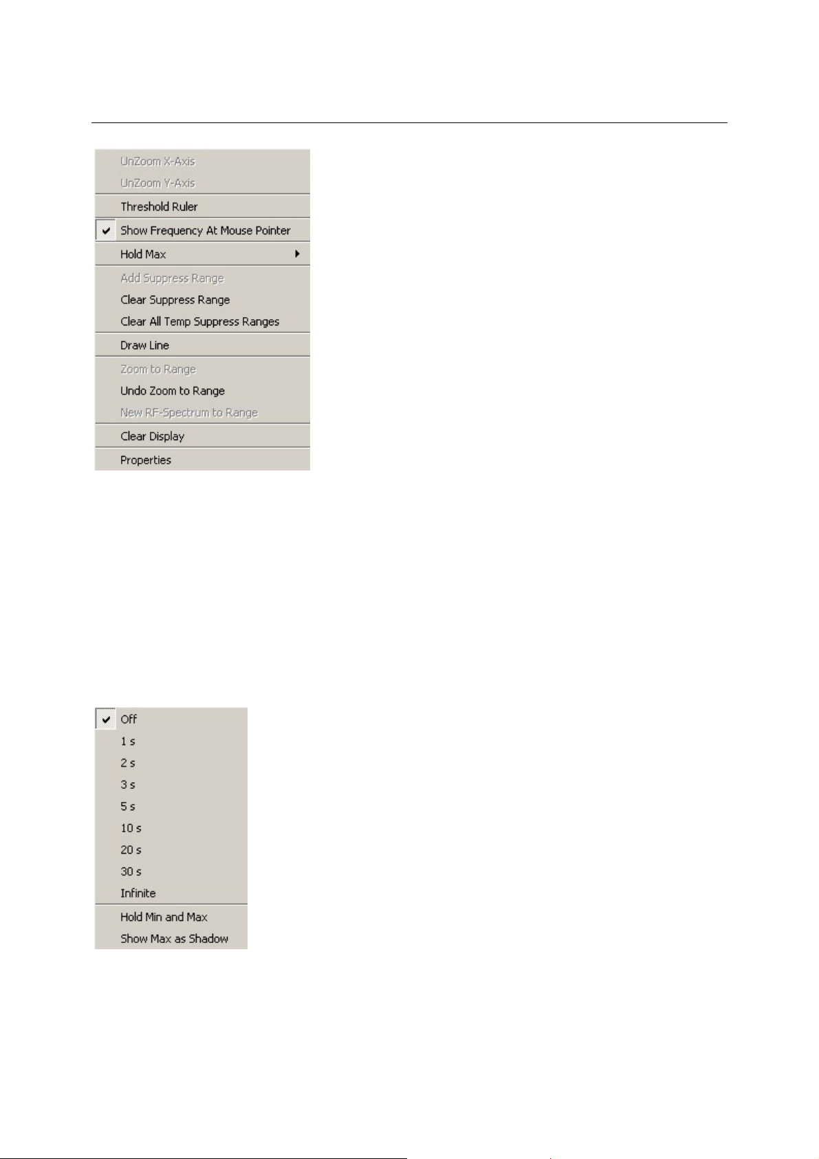
Press the right mouse button in the RF-spectrum display. The following menu will pop up:
3020.8306.02 36 E-1.1
Page 38
PR/EM100 Control Operating Instructions
Most of the items available have been described in the previous pages. The remaining items are
described as follows.
Threshold Ruler:
A horizontal ruler will be shown in the RF-spectrum display. This ruler may be used to display the
current threshold value.
Show Frequency At Mouse Pointer:
The frequency value of the current mouse pointer position will be displayed in the frequency scale.
Hold Max:
This sub-menu is used to configure the hold-max feature of the RF-spectrum. The spectrum will display
the current level values as well as the maximum level value that occurred during the last time period
selected. The maximum is represented by a dotted line. Alternatively, it may be displayed by a dark
green shadow. Besides this, the minimum values may also be displayed.
3020.8306.02 37 E-1.1
Page 39

PR/EM100 Control Operating Instructions
Clear Display:
The whole RF-spectrum display will be cleared.
Zooming the frequency axis:
• Use the left-hand mouse button to click on the minimum frequency of the zoom range in the RF
frequency scale.
• Keep the mouse button pressed and drag the mouse to the maximum frequency in the RF
frequency scale. The selected frequency range is displayed light grey.
Figure 3-3 Zooming in with the Mouse (X Axis of Spectrum Display)
• The frequency axis is zoomed by releasing the mouse button.
Shift the axis range:
• Use the
Shift the zoomed frequency range:
• When the frequency axis is zoomed, the zoomed frequency range can be shifted:
Press the Shift key and click on the frequency axis with the left-hand mouse button. While
keeping the mouse button and the Shift key pressed, shift the frequency axis to the left (lower
frequencies) or to the right side (higher frequencies).
Release the Shift key and the mouse button.
Un-zoom the frequency axis:
• Click on the frequency scale with the right-hand mouse button.
• Click on the UnZoom X-Axis entry of the pop-up menu.
• The frequency axis can be un-zoomed in several steps.
• Another way to Un-Zoom the frequency axis is a double-click on the RF frequency scale. The
first double-click un-zooms to the defined Search range, the second to the whole range of the
device, and so on.
Another way to zoom/un-zoom the frequency axis is to use the frequency rulers and press F10/F11
(see Setting frequency rulers on the following pages).
Change the unit of the frequency Axis:
• Click into the Frequency Control and press
m for MHz
/ buttons next to the axis to move the whole axis to the right / left.
3020.8306.02 38 E-1.1
Page 40

PR/EM100 Control Operating Instructions
k for kHz
g
Popup Menu:
Right click the axis to open the context menu:
•
for GHz
3020.8306.02 39 E-1.1
Page 41

PR/EM100 Control Operating Instructions
Center of
Hide all Ruler hides all rulers except the yellow frequency ruler.
arker Frequency toggle visibility of the yellow frequency marker in drawpanes such as
M
spectrum or waterfall. The frequency marker cannot be hidden on the
axis itself.
Additional #xxx toggle visibility of additional markers. Once you have at least one
additional marker visible, use [CTRL] + [TAB] for interchange the
frequency and the last additional frequency. Use this for medium fast
witching contexts in e.g. intercom systems.
s
Mouse moving marker toggle visibility of the mouse frequency position on the frequency axis.
Maximum Range set the axis range to the maximum currently available range.
Default Range set the axis range to the current default – the current job.
UnZoom UnZoom if available
Properties Open frequency properties:
• Right click a visible marker on the axis to display its context menu:
o Toggle marker visibility
o Toggle result panel for this ruler if available.
Setting the frequency rulers for range selection:
• Click into the RF spectrum display with the left-hand mouse button. Keep the left-hand mouse
button pressed and drag left to define the frequency range. Release the mouse button. There
are now two orange vertical rulers which enclose the selected frequency range.
• The frequencies of both vertical rulers (start and stop frequency of the selected range) as well
as the difference between the rulers are displayed under the RF display.
Start
Frequency
Figure 3-4 X-Ruler Values Toolbar Fields
3020.8306.02 40 E-1.1
Frequency
Span
Stop
Frequency
Center
Button
range
Page 42

PR/EM100 Control Operating Instructions
Figure 3-5 Frequency Range Selection
There are two ways to delete the range selection:
• Use the Escape key to delete the range selection.
• Click into the RF spectrum with the left-hand mouse button. The vertical orange rulers will
disappear and the yellow frequency ruler will be set.
Y-Axis with threshold ruler in
visible area
Zooming the level axis:
• Use the left-hand mouse button to click on the minimum frequency of the zoom range in the
level scale.
• Keep the mouse button pressed and drag the mouse to the maximum level in the scale. The
selected level range is displayed light grey.
• The frequency axis is zoomed by releasing the mouse button.
• If the threshold (white marker) is outside the visible area of the axis, a little white triangle is
shown top or bottom of the axis, wherever the threshold is. A click on this triangle will enlarge
the zoomed area until the threshold ruler is visible again.
Shift the zoomed level range:
• While the level axis is zoomed, the zoomed frequency range can be shifted:
Press the Shift key and click on the axis with the left-hand mouse button. While keeping the
mouse button and the Shift key pressed, shift the axis up or down. Release the Shift key and
the mouse button.
Un-zoom the level axis:
• Click on the scale with the right-hand mouse button.
• Click on the UnZoom X-Axis entry of the pop-up menu.
• The axis can be un-zoomed in several steps.
Y-Axis while zoom Y-Axis with threshold ruler
outside visible area
Popup Menu:
• Right click the axis to open the context menu:
3020.8306.02 41 E-1.1
Page 43

PR/EM100 Control Operating Instructions
RF Level Span
Lower Level Ruler
Center Butto
n
Level Threshold toggle visibility of the white threshold marker in the drawpane. The
threshold marker cannot be hidden on the axis itself.
Default Range apply a zoom so that the displayed curve is fully visible
Maximum Range zoom to the maximum available level range
UnZoom UnZoom if available
• Right click the threshold marker directly on the axis to toggle the visibility of the ruler via its
menu. Notice: while changing the threshold value, the ruler is always visible.
Setting the horizontal RF level rulers for RF level measurement:
• Press the Shift key and click (left-hand mouse button) into the RF spectrum. Keep the left-hand
mouse button pressed and drag down/up to define the level range. Release the mouse button.
There are now two orange horizontal rulers which enclose the selected level range.
• The levels of both horizontal rulers (start and stop level of the selected range) as well as the
difference between the rulers are displayed on the left side of the RF display.
Upper Level Ruler
Center Ruler
• Both rulers can be dragged with the left-hand mouse button.
• The selection can be canceled by clicking (left-hand mouse button) into the RF spectrum or by
pressing the Escape key.
3020.8306.02 42 E-1.1
Page 44

PR/EM100 Control Operating Instructions
3.7.2 RF-Waterfall Display
In the RF-waterfall all active frequencies of the RF-spectrum over a certain period of time are displayed
in form of a waterfall.
Each horizontal line represents a measured curve color coded. The color code is displayed at the left
side of the waterfall and on the right side of the correlated overview widget. New lines are inserted at
the top and the previous lines are moved towards the bottom of the widget - so the moving contents of
this widget look like a colored waterfall.
In the title bar of the waterfall at the left side, the timestamp when the last line was inserted is displayed.
On the right side, the current time resolution is displayed.
Waterfall Properties:
The waterfall properties and the Fill Gaps-mode are available through the properties dialog via context
menu.
Select Fill Gaps to enlarge each channel value to its width visually. A difference may be seen only if
there are less channels then pixels available.
Only one line per channels is visible, in between
the channels, the waterfall stays black.
“Fill Gaps” enabled: each channel is expanded to
it’s channel bandwidth.
3020.8306.02 43 E-1.1
Page 45

PR/EM100 Control Operating Instructions
Properties will open the property page:
Common Settings:
• Clear on Resize only: Waterfall will cleared only on resize. Per default, this flag is not set – so
the waterfall is cleared when the channel range to be displayed changes or display settings are
changed. On Resize, the waterfall must be cleared.
• Insert Stopped Bar on halted: If enabled, a “Stopped Bar” is inserted to the waterfall, when the
waterfall was stopped, so that you can distinguish continuous scopes from each other.
• Draw while minimized forces the waterfall to draw even while the window is hidden. – This may
lead to decreased over all performance.
Speed:
• Device controlled: Waterfall speed is optimized to the scan speed. For each scan, one line will
be inserted.
• Time controlled forces a fixed line feed independently from data.
Length:
• You may allow the waterfall size larger than the current window size (in time- direction) – This
may lead to decreased over all performance.
Due to speed settings, the time axis changes:
3020.8306.02 44 E-1.1
Page 46

PR/EM100 Control Operating Instructions
Waterfall axis with fixed linefeed
Waterfall Modes:
• The waterfall axis (left side) may be toggled from fixed mode (means n lines per second) to
device mode.
• In fixed mode, lines are inserted via an independently running timer. If no new data is sent from
the device for this timeslot, the last dataset will be inserted again. If there is more data then one
single line, data will be compressed and only one line will be inserted. Compression works on
finding the maxima per pixel displayed.
• In device controlled mode, a line feed in the waterfall is triggered from the device respectively
the device driver. If too many data is sent too fast, driver compresses data by maximum finding
and a fixed timeslot. The axis shows minutes and seconds in the format [mm]:[ss] – for the full
timestamp see the caption
• In local mode – when driver and gui run on the same machine, there is a fast waterfall
available, where all frames are displayed – switch to fast waterfall by clicking to the
in the caption. If there is no such button you are probably working in remote mode.
Shift the axis range:
• If they are available, use the
the axis. While the axis is shifted, no new lines are inserted. Shifting is available, when “Allow
Waterfall larger than window” is set in the waterfall property page and a number of lines is
entered which is larger than the current widget.
Device controlled waterfall axis
(down), (pagepown), (pageup) and (up) buttons to shift
button
Freeze:
The waterfall display may be stopped by clicking on the Freeze button
mode:
Set the horizontal time rulers for time measurement:
• Press the Shift key and click with the left mouse button into the waterfall. Keep the left mouse
button pressed and drag down/up to define the time range. Release the mouse button. There
now are two orange horizontal rulers which enclose the selected time range.
• The time stamps of both horizontal rulers (start and stop time of the selected range) as well as
the difference between them are displayed on the left side of the RF waterfall display. These
timestamps are also shown in ms resolution in the caption bar of the control.
• Both rulers can be dragged with the left mouse button. The timestamps changes according to
the ruler position.
3020.8306.02 45 E-1.1
or be starting a measurement
Page 47

PR/EM100 Control Operating Instructions
• The selection can be canceled by clicking with the left mouse button into the RF-waterfall
display or by pressing the Escape key.
3020.8306.02 46 E-1.1
Page 48

PR/EM100 Control Operating Instructions
Setting time and frequency rulers for measurement:
ike above, without shift-key.
L
• Click with the left mouse button into the waterfall. Keep the left mouse button pressed and drag
down/up to define the time range. Release the mouse button. There now are four orange
orizontal rulers which enclose the selected time range.
h
Setting multiple time and frequency rulers for measurement:
Like above, with ctrl-key.
• Keep ctrl-key pressed. Click with the left mouse button into the waterfall. Keep the left mouse
button pressed and drag down/up to define the time range. Release the mouse button. There
now are four orange horizontal rulers which enclose the selected time range.
• Repeat the last paragraph to select multiple ranges.
• Use ctrl+tab to switch the ruler selection and the displayed numeric values.
3.7.2.1 Color Settings
With this dialog the user can create new colorsets and add them to the predefined colorsets.
Waterfall Colors
There are 3 sets of user-defined waterfall colors: ‘User defined (n)’.
• Select the waterfall color set to change.
• Select the number of colors the set contains.
• Select ‘Smooth’ to get a continuous transition between colors.
3020.8306.02 47 E-1.1
Page 49

PR/EM100 Control Operating Instructions
• Select ‘Use fixed correlation’ to fix the colors assigned to a value, e.g. to assign the red to values 0
to 50. Otherwise, the colors will be applied to the range of the correlated axis. You may also select
“Wrap around” and enter an optional offset. This is useful, if you define e.g. an Azimuth Color Set:
o Select “fixed correlation” and values from 0 to 359.99. (degrees)
Select “wrap around”
o
o If, at your current location, you are especially interested in Values from 30 to 60
degrees, set these colors to e.g. red, all others to e.g. black.
o After moving your location, you are maybe interested in values from 40 to 70 degrees.
To adapt the colorset to this new situation, simply add an offset of 10.
• Select the color in the ‘Index’ field and assign a shade by selecting it with the cross cursor in ‘Select
Colors’.
• Select “Use Minimum Color for Background”, if you don’t want to use the standard background
color. You need this flag for distinguish “no value at all” from “maximum value” if your colorset
defines e.g. white for the minimum and black the maximum, while the background of the waterfall ist
set to black.
The resulting waterfall is shown in the ‘Result’ field.
Common Colors
The tab Common Colors is used to define colors of the user interface, e.g. the text or background
colors.
• Select the element you want to change e.g. Drawpane for waterfalls, overviews etc.
• Select the colorrole to be set, e.g. “Background” and select the color, you want to use:
there are two different types of colors to use:
o Fixed Colors “Black”, “Blue, “Green” etc…
o System Colors “System::Background”, “System::Caption”, etc…
3020.8306.02 48 E-1.1
Page 50

PR/EM100 Control Operating Instructions
Whenever possible, prefer system colors, they will change automatically with windows when you
hange the colors of windows. In the picture below, “Background in Job” will stay “Gray” but
c
“Background out of Job” will float with your windows theme.
• Click Apply to see the result immediately.
• Change other colors as necessary.
• Save the color set with the Save button.
• To load a previously saved set use the Load button.
3.7.3 RF-Fast-Waterfall Display
Switch to the Fast Waterfall by clicking the
run the program in local mode, means: driver and gui run on the same machine.
If the button is not visible, no data for the Fast Waterfall are available: you probably run in
remote
3020.8306.02 49 E-1.1
button in the caption. This feature is only available if you
Page 51
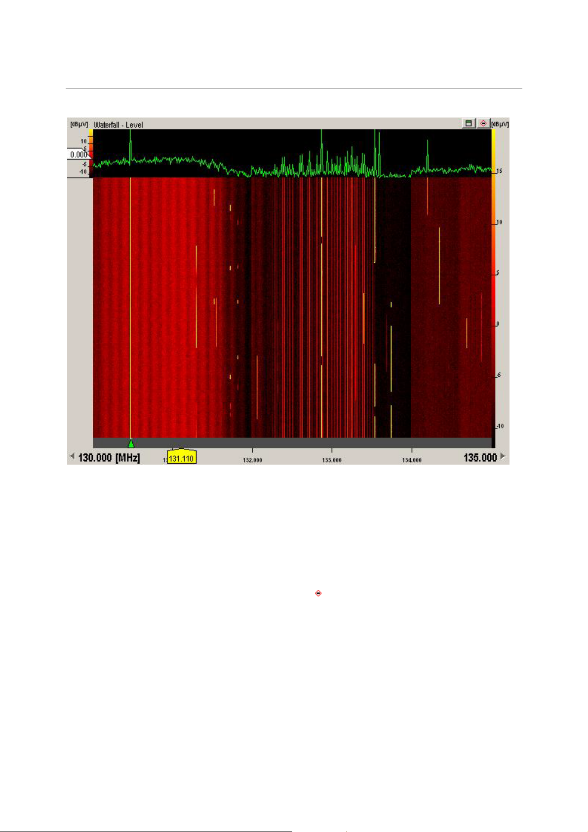
PR/EM100 Control Operating Instructions
mod
• The fast waterfall control display the curve and the current waterfall as fast as they are received
from the device. No frames are lost.
• For the sake of speed and performance, no display options and no rulers can be set.
• For the same reason, caption and waterfall axis is not updated during scan, unless the waterfall
is stopped.
• Enter the measurement mode by clicking the
range in the waterfall.
stop button in the caption or by selecting a
3020.8306.02 50 E-1.1
Page 52

PR/EM100 Control Operating Instructions
Measurement Modes:
ange Measurement
R
• For to enter this measurement mode, just click into the waterfall (running or not), keep the
mouse button pressed, drag and release.
• Once the rulers are visible move the mouse over the rulers so that the mouse pointer changes,
press the mouse button and drag the ruler for fine tuning.
• Press [space] bar to toggle visibility of the result panel. The result panel displays only
differences in this mode, so you may measure the exact length of a signal or the bandwidth of a
signal.
• Use [Ctrl]+mouse drag & release to select more than one range. Once you have more than one
created, use [Ctrl]+[tab] to switch contexts fast.
Use this feature to compare different emissions in length (time) and bandwidth.
• Press [esc] to leave this measurement mode and start the Single Line Measurement or press
Stop button to restart the waterfall.
3020.8306.02 51 E-1.1
Page 53
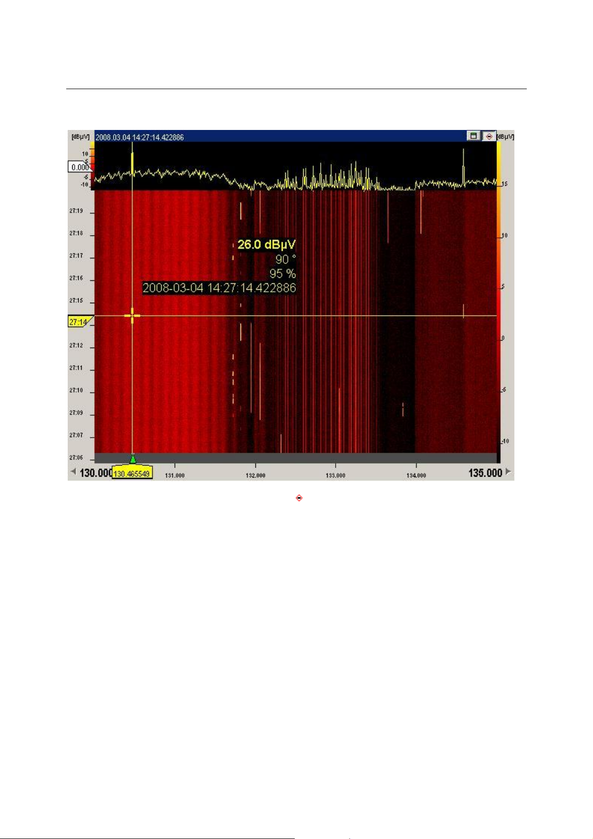
PR/EM100 Control Operating Instructions
Single Line Measurement
• For to enter this measurement mode, click Stop button while waterfall is running or press
[esc] during range measurement mode.
• The overview graph displays data received at the timestamp selected by the yellow time-ruler.
Move time ruler to view the curve at a specified time.
• Use [space] bar to toggle the result panel, which displays the data selected.
• Use [esc] to leave this measurement mode and restart the waterfall.
3020.8306.02 52 E-1.1
Page 54

PR/EM100 Control Operating Instructions
3.7.4 IF-Spectrum Display
In FFM and Search Mode, the IF spectrum can be displayed in the graphical window. This Display is
only shown, if the SU option is valid in the device. By pressing the F9 Key the IF spectrum display can
be activated and deactivated.
The frequency span can be set by clicking on the frequency field on the right side of the x-axis and
selecting a suitable value. The following list offers the available half-widths, that means the difference
between center frequency and the upper and lower limits. The whole displayed IF-range is twice as
large!
Absolute/Relative values set the labelling of the x-axis to absolute (start – stop) or relative values
(center and +/- offset).
IF-Display context menu:
Press the right mouse button inside the IF-display to show the context menu.
3020.8306.02 53 E-1.1
Page 55

PR/EM100 Control Operating Instructions
Four different IF measuring modes are available here. (not in firmware version equal to or below 1.22)
• Clear Write
• Min Hold
• Max Hold
• Average
The selected Mode is also displayed in the right upper corner of the IF-spectrum display.
Please refer to the PR/EM100 device manual for detailed information about the modes.
Threshold Ruler:
A horizontal ruler will be shown in the IF-spectrum display. This ruler may be used to display the current
threshold value.
Show Frequency At Mouse Pointer:
The frequency value of the current mouse pointer position will be displayed in the frequency scale.
Properties
The IF Properties dialog is very similar to the RF Properties dialog. Please refer to the RF Properties
dialog section in this manual.
3020.8306.02 54 E-1.1
Page 56

PR/EM100 Control Operating Instructions
3.7.5 IF-Waterfall Display
The IF-Waterfall display is very similar to the RF-Waterfall display. Please refer to the RF-Waterfall
display section in this manual.
3.8 Status bar
The status bar displays information about the status and the actual mode of operation of the
PR/EM100.
The left side of the status bar defines the message area, wherein messages are shown in plaintext.
3.9 Create Reports (Option)
Sends the monitored results to the inbox of the application ReportEdit by clicking with the left mouse
button on the menu item. Clicking with the right mouse button will show a context menu to allow the
user the selection of the sending method :
It is also possible to connect and disconnect to ReportEdit. Note that the report application ReportEdit
must be started to perform reports! The connection state can be seen by inspecting the ReportEdit icon.
If it is crossed out, no connection exists. See the ReportEdit Manual for further information.
3.10 Recording (Option)
Click on the button to start recording. Click again to stop recording.
The data are saved in a recording file. This file contains information about time, frequency, level, etc.
and can be used for later evaluation with tools like ScanReplay or ActivityAnalyzer.
Click on the arrow key beside the recording button to open the recording menu.
The following menu functions are available:
- Menu Off switches recording off
- Menu On switches recording on
- Menu Recording Status Dlg... popups the recording Status Dialoge
3020.8306.02 55 E-1.1
Page 57

PR/EM100 Control Operating Instructions
The recording status dialogue contains informations about the actual Recording file e.g. filename,
ilesize, recording directory, start and stop time, available diskspace and a warning level when
f
exceeding a particular disk amount.
For further information about the recording status, see the document: HowToUse RecStatus.doc
3.11 IF-Recording (Option)
Click on the button to start an IF-Recording in FFM mode.
The recorded data will be saved to a WAV-File in the configured directory. The filename contains
information about the recording date and time. Further analysis of the recording can be done using
AmLab or similar tools.
The status of the recording can either be “running” or “off”. In state running the small bar inside the
button will be illuminated in green, otherwise it will be gray.
The recording bandwidth and frequency are taken from the current settings in the user interface. If a
bandwidth higher than the maximum allowed for the recording is selected it will automatically be
changed. This limitation is due to the maximum throughput of the network.
But also at lower bandwith settings there is a possibility that packet loss will be experienced. This leads
to gaps in the time resolution of the recording. It is especially likely to happen at high bandwidths
(>300kHz) where the network usage is near its maximum (for 100MBit connections), if the computer is
busy doing other tasks or if the harddisk is under heavy usage so that the data cannot be written in
time.
If packet loss is experienced it is advisable to reduce other network traffic and shutdown other tasks
currently running on the computer.
3.12 Audio-Recording (not with firmware versions equal to or lower than 1.22)
By clicking on the Audio-Recording button , located right next to the IF-Recording button, an audio
recording of the current audio output with the current quality settings is started. Clicking again will stop
the recording. The output is even recorded if the audio output is muted at the time of recording. After
stopping the recording activity a *.wav file is written to the standard recording directory (most likely
D:\RamonData\Recording\PR100). These audio files can be played back with any standard
mediaplayer like the Windows Media Player, Quicktime, VLC or MPlayer. The name of the files will
include all the relevant information, such as the recording time, recorded frequency, demodulation
bandwidth and demodulation type.
3.13 Instant Replay
Click on the button to open the instant replay window.
Loading Data
After starting the Instant Replay the actual data of the PR/EM100 application window is copied to the
instant replay window.
3020.8306.02 56 E-1.1
Page 58

PR/EM100 Control Operating Instructions
The title bar shows the time range of the recorded data and the number of data frames.
Hint:
The waterfall and spectrum windows are implemented as the according windows in the PR/EM100 main
application and offer the same functionality and features (e.g. cursor measurement).
3.13.1 File Menu
Exit
Closes the instant replay window
3020.8306.02 57 E-1.1
Page 59

PR/EM100 Control Operating Instructions
3.13.2 Instant Replay Toolbar
Goto Start
By clicking on the Goto Start button
slider are set to the start of the recorded data.
One Frame Back
By clicking on the One Frame Back button
Stop/Hold/Pause
By clicking on the Stop/Hold/Pause button
be resumed by any of the Rewind/Play/Forward buttons.
One Frame Forward
By clicking on the Fast Forward button
Play
By clicking on the Play button
Fast Play
By clicking on the Fast Play button
Goto End
By clicking on the Goto End button
slider are set to the end of the recorded data.
Position slider
the recorded data are shown.
the position of the actual spectrum cursur and the position
the frame before the actual one is displayed.
the playback of the recorded data is stopped and can
the recorded data are shown accelerated.
the recorded data are shown accelerated.
the position of the actual spectrum cursur and the position
With this slider
the recorded data can be variied.
3020.8306.02 58 E-1.1
, the position within
Page 60

PR/EM100 Control Operating Instructions
3.14 Function Keys/ Hot Keys
Selecting the Menu Help – Keyboard displays the availabe Function and Hot Keys.
3020.8306.02 59 E-1.1
Page 61

PR/EM100 Control Typical Operation
4 Typical Operation
4.1 General
The PR/EM100 Control is a versatile software designed to allow the operator to receive radio signals,
search and scan through radio frequencies for signals and measure frequency occupancy and
coverage using a PR/EM100 Device.
Emitter
PC
Network
C
P
Device Modules
Antennas
The Operator can use the PR/EM100 Control software to manually tune into radio signals for
monitoring and recording on the device. The operator can also define a set of search criteria, which
can be used in an overview mode to scan for signals that may be of interest.
Any signals found by the PR/EM100 Control software during the scan can be analysed by the
operator. Additionally, their activity may be monitored and recordings of signals can be made. The
operator can listen to the signals by switching on the speaker of the PR/EM100 device.
Note:
Digital audio signals can be distributed or recorded in LAN/WAN area using the Rohde&Schwarz
AllAudio application. This is an additional software package which is not included in the PR/EM100
Control software. Please contact your local Rohde&Schwarz sales office for more information. In
addition to that the PR/EM100 Control gives the possibility to distribute the Audio output of the device
to the local soundcard on your PC.
The PR/EM100 Control application provides an easy way of controlling the PR/EM100 within a
monitoring system. Using the application the operator is able to
• set all important parameters of the PR/EM100,
• monitor single frequencies including aural monitoring,
• obtain an overview of the signal activities in a selected frequency range by watching the RF-
spectrum display while scanning,
• perform a panorama scan (PSCAN) of the selected frequency range and watch the RFspectrum display,
• search for active signals in a selected frequency range,
• perform a BIT (built in test) of the PR/EM100,
• reset the PR/EM100.
4.2 Monitor Single Frequencies
If the frequency to be monitored is known it can be entered quickly in the following way:
• Switch to the Fixed Frequency Mode with function key F2 or by pressing the
toolbar.
• Use the function key F6 to select the frequency edit field and enter the frequency numerically
using the numerical key pad and pressing Enter.
Bandwidth and modulation should be adjusted as appropriate using the controls located in the main
toolbar (see chapter 3.6.1).
3020.8306.02 60 E-1.1
button in the
Page 62

PR/EM100 Control Typical Operation
The operator has to decide if he wants to use AFC for monitoring. Additionally Level Indication and
Gain Control can be set.
f the operator detects an interesting signal, he may add the corresponding frequency to a single
I
frequency list (see chapter Frequency Store).
4.3 Frequency Scan (not with firmware versions equal to or lower than 1.22)
The PR/EM100 Control application provides possibilities for the remote control of the PR/EM100 as a
scanning receiver within a monitoring and measurement system.
The operator has two possibilities for scanning:
• Frequency Scan is used to obtain an overview of activities in a selected frequency range.
• PSCAN is used to get a very fast overview over a selected frequency range.
In the SCAN / Search toolbar the operator defines the parameters for scanning; then he starts the
frequency scan either via the Scan
spectrum of the selected frequency range is displayed in the RF-spectrum area. The operator obtains
an overview of the signal activities in the selected frequency range. In order to detect interesting
signals it is possible to zoom into the frequency range in several steps. Besides this, the operator may
examine the RF-waterfall.
An interesting frequency may be marked with the frequency marker of the RF-spectrum display. After
the operator stops scanning, the PR/EM100 remains on the selected frequency and the operator may
listen to the audio of this signal.
The operator may start
Typical steps for performing a frequency scan with the PR/EM100 Control application are:
• Define the scan parameters in the Modus Editor toolbar.
• Start scanning the selected frequency range by clicking on the Scan button
Start- and stop frequency of the frequency range are displayed below the RF-spectrum
display.
• Set the RF-threshold.
• Watch the RF-spectrum display of the PR/EM100 Control application to obtain an overview of
the signal activities in the selected frequency range.
• Zoom into interesting areas of the spectrum display in several steps. Zoom out again.
• Set the frequency marker to interesting signals in the RF-spectrum display in order to view the
corresponding frequency and the level.
• Stop scanning by clicking on the FFM button
refer to the last section for information about monitoring single frequencies and handling the
audio function.
PSCAN
PSCAN is used to scan the frequency range of interest with nearly 10 MHz Steps and performing a
high resolution FFT at each step.
Note: PSCAN is available if the device option “PS” is installed.
For PSCAN the operator defines the parameters for scanning (start, stop and step frequency) in the
scanning by pressing the appropriate button in the toolbar.
button in the toolbar or via the function key Shift+F4. The
to monitor the selected frequency. Please
.
PSCAN toolbar and starts the PSCAN (either by the button in the toolbar
the function key F4). The step frequencies can be selected from the discrete values 3.125 kHz, 6.25
kHz, 12.5 kHz, 25 kHz, 50 kHz and 100 kHz. Other values will be set to the next possible value
automatically when the PSCAN has been started.
The spectrum of the selected frequency range is displayed in the RF-spectrum area. The operator
quickly obtains an overview of the signal activities in the selected frequency range. In order to detect
interesting signals it is possible to zoom into the frequency range in several steps.
3020.8306.02 61 E-1.1
, via the menu entry or
Page 63

PR/EM100 Control Typical Operation
4.4 Search (not with firmware versions equal to or lower than 1.22)
The PR/EM100 Control application provides possibilities for the remote control of the PR/EM100 as
searching receiver within a monitoring and measurement system.
fter having obtained an overview of activities by scanning, searching is used to monitor interesting
A
frequencies and frequency ranges for activities.
The operator defines a frequency range in order to search for active signals. Additionally he has to
define the stepwidth, the dwell time and set the signal threshold. The PR/EM100 stops at each signal
with signal level over threshold. During the dwell time the operator may monitor the signal. If the
operator is not interested in a signal he may continue searching before the dwell time has elapsed.
Typical steps for using the PR/EM100 as a searching receiver in the PR/EM100 Control application
are:
• Define the search parameters in the SCAN toolbar.
• Searching starts at the currently selected reference frequency. You may change the start
frequency by setting another reference frequency.
• Set the volume of the audio to a suitable value.
• Start searching for active signals by clicking on the Search button
The search starts at the current position of the reference frequency ruler.
• Set the threshold according to the signal activity in the selected frequency range by dragging
the white threshold label in the RF-spectrum display.
• Frequency and signal level of the detected signals are displayed during the dwell time. Set
bandwidth and modulation according to the detected signal.
• Press the Continue button (Continue menu item)
signal and want to continue searching before the dwell time has elapsed
• Select the Suppress menu
suppress this frequency.
if you are no longer interested in the signal and want to
if you are no longer interested in the
, or with function key F3.
4.5 MScan / MSearch (not with firmware versions equal to or lower than 1.22)
In addition to the workflows described in the Scan and Search sections above, the operator can
perform Scan and Search activities not only using ranges, but also using frequency lists.
This can be done as follows:
• The frequencies that should be used for a MScan / MSearch must be marked active in the
Frequency Store of the PR/EM100 GUI.
• For a MSearch, setup the dwell and hold times in the MSearch configuration dialog
• Press the MScan
• The further handling of a MScan / MSearch is similar to the handling of a Scan / Search as
described above.
3020.8306.02 62 E-1.1
or MSearch button to start the measurement.
Page 64

PR/EM100 Control Typical Operation
4.6 Client Server Remote Control as Option (RA-RC)
Remote Control is only available for the PR/EM100 Control as part of a Ramon System. With Remote
Control you can install a PR/EM100 Driver on a PC directly connected to the device. The driver is
esponsible for the communication with the device.
r
On a Remote PC a PR/EM100 GUI can be installed. This GUI will communicate with the PR/EM100
driver via LAN in the network. With Remote Control it is possible to Control several devices with
several GUIs remotely without the devices being near the Remote PC.
If the PR/EM100 GUI is installed and correctly configured, the PR/EM100 can be remote controlled
from
• The PC that is connected to the PR/EM100 device via Ethernet LAN and where the
PR/EM100 driver is running.
• Other PC’s which have network access to the PC that is directly connected to the
PR/EM100 device.
One PR/EM100 device can be remote controlled by more than one PR/EM100 GUI application at the
same time. If one remote operator changes the settings of the PR/EM100, the changed settings will be
displayed at all connected PR/EM100 GUI applications.
3020.8306.02 63 E-1.1
Page 65

PR/EM100 Control Typical Operation
5 Appendix
5.1 Overview of the Antenna.txt file
The Antenna.txt file contains a list of items that will be filled into the Antenna selection control (see
chapter 3.6.2). Each line in the file represents an item in the list. Lines may be added, removed or
modified for adjusting the software to the user’s individual requirements.
VSC
// Format:
//AntennaName[tab]Number[tab]Number
// Index 1 will be set to the current selected value after loading:
TESTANT 0 0
ANTENNA_1 1 1
ANTENNA_2 2 2
ANTENNA_3 3 3
ANTENNA_4 4 4
ANTENNA_5 5 5
ANTENNA_6 6 6
ANTENNA_7 7 7
ANTENNA_8 8 8
ANTENNA_9 9 9
ANTENNA_10 10 10
ANTENNA_11 11 11
ANTENNA_12 12 12
The <Number> of an item will be set in the device, i.e. if ANT_VERTICAL is selected in the EMx50
GUI, antenna no. 1 will be selected in the device.
Note:
Do not remove the “VSC” tag at the very beginning of the file.
It is strongly recommended to create a backup of a working Antenna.txt file before modifying the file.
The user is responsible for any errors or damage that occur because of a wrong Antenna.txt file!
3020.8306.02 64 E-1.1
 Loading...