


R&S®OSP-B200R/B200S2
Satellite System for R&S®OSP
User Manual
(;ÜÑQ2)
1178673302
Version 03

This user manual describes the following satellite system models:
●
R&S®OSP-B200R Remote Control Module (order no. 1528.3140K02)
●
R&S®OSP-B200R Remote Control Module with FOL (order no. 1528.3140K04)
●
R&S®OSP-B200S2 Satellite Unit (order no. 1528.3134K02)
●
R&S®OSP-B200S2 Satellite Unit with FOL (order no. 1528.3134K04)
It describes also the following satellite system accessories, see Chapter 4.3:
●
R&S®OSP-B200P Power Supply (order no. 1528.3205.02)
●
R&S®OSP-Z200x 5 m to 10 m Wired Link Cable (order no. 1528.3170.xx)
●
R&S®OSP-Z201x 5 m to 40 m FOL Cable, SC/SC (order no. 1528.3186.xx)
●
R&S®OSP-Z203xF 0.5 m to 40 m FOL Cable, SC/FSMA (order no. 1528.1690.xx)
●
R&S®OSP-Z204xF 0.5 m to 40 m FOL Cable, FSMA/FSMA (order no. 1528.1702.xx)
© 2021 Rohde & Schwarz GmbH & Co. KG
Mühldorfstr. 15, 81671 München, Germany
Phone: +49 89 41 29 - 0
Email: info@rohde-schwarz.com
Internet: www.rohde-schwarz.com
Subject to change – data without tolerance limits is not binding.
R&S® is a registered trademark of Rohde & Schwarz GmbH & Co. KG.
Trade names are trademarks of the owners.
1178.6733.02 | Version 03 | R&S®OSP-B200R/B200S2
Throughout this manual, products from Rohde & Schwarz are indicated without the ® symbol , e.g. R&S®OSP-B200R is indicated as
R&S OSP-B200R.

R&S®OSP-B200R/B200S2
Contents
1 Safety and Regulatory Information...................................................... 5
1.1 Safety Instructions........................................................................................................5
1.2 Labels on the Product.................................................................................................. 8
1.3 Warning Messages in the Documentation..................................................................8
1.4 Korea Certification Class B..........................................................................................9
2 Key Features.........................................................................................10
3 Documentation Overview.................................................................... 11
3.1 User Manual................................................................................................................. 11
3.2 Manuals of the Base Switch Units............................................................................. 11
3.3 Printed Safety Instructions.........................................................................................11
Contents
3.4 R&S OSP on the Internet............................................................................................ 11
3.5 Data Sheets and Brochures....................................................................................... 12
3.6 Application Notes, Application Cards.......................................................................12
3.7 Drivers..........................................................................................................................12
3.8 Release Notes and Open Source Acknowledgment................................................ 12
4 Hardware Description..........................................................................13
4.1 Remote Control Interface Module R&S OSP-B200R................................................ 13
4.2 Satellite Unit R&S OSP-B200S2................................................................................. 14
4.3 Accessories for the Satellite System........................................................................ 15
5 Preparing for Use.................................................................................17
5.1 Unpacking and Checking........................................................................................... 17
5.2 Mounting the RC Module into a Base Unit................................................................17
5.3 Mounting a Switch Module into the Satellite............................................................ 18
5.4 Connecting the Satellite System's Components......................................................19
6 Operating the Satellite System........................................................... 23
6.1 System Status............................................................................................................. 23
6.2 Power Consumption................................................................................................... 23
7 Transporting, Storage and Disposal.................................................. 24
7.1 Transporting................................................................................................................ 24
3User Manual 1178.6733.02 ─ 03

R&S®OSP-B200R/B200S2
7.2 Storage.........................................................................................................................24
7.3 Disposal....................................................................................................................... 24
8 Maintenance......................................................................................... 25
8.1 Cleaning....................................................................................................................... 25
8.2 Maintaining Flawless FOL Connections................................................................... 25
8.3 Contacting Customer Support...................................................................................27
Contents
4User Manual 1178.6733.02 ─ 03

R&S®OSP-B200R/B200S2
1 Safety and Regulatory Information
The product documentation helps you use the product safely and efficiently. Follow the
instructions provided here and in the Chapter 1.1, "Safety Instructions", on page 5.
Intended use
The R&S OSP-B200R/B200S2 is designated for switching and control applications,
including RF switching, in industrial, administrative, and laboratory environments. Use
the R&S OSP-B200R/B200S2 together with the R&S OSP base switch units, see
Chapter 2, "Key Features", on page 10, and only for its designated purpose.
Observe the operating conditions and performance limits stated in the data sheet.
Target audience
This document is targeted at all users, including installers, operators, and maintenance
personnel.
Safety and Regulatory Information
Safety Instructions
Where do I find safety information?
Safety information is part of the product documentation. It warns you of potential dangers and gives instructions on how to prevent personal injury or damage caused by
dangerous situations. Safety information is provided as follows:
●
In Chapter 1.1, "Safety Instructions", on page 5. The same information is provided in many languages as printed "Safety Instructions". The printed "Safety
Instructions" are delivered with the product.
●
Throughout the documentation, safety instructions are provided when you need to
take care during setup or operation.
1.1 Safety Instructions
Products from the Rohde & Schwarz group of companies are manufactured according
to the highest technical standards. To use the products safely, follow the instructions
provided here and in the product documentation. Keep the product documentation
nearby and offer it to other users.
Use the product only for its intended use and within its performance limits. Intended
use and limits are described in the product documentation such as the data sheet,
manuals and the printed safety instructions. If you are unsure about the appropriate
use, contact Rohde & Schwarz customer service.
Using the product requires specialists or specially trained personnel. These users also
need sound knowledge of at least one of the languages in which the user interfaces
and the product documentation are available.
If any part of the product is damaged or broken, stop using the product. Never open
the casing of the product. Only service personnel authorized by Rohde & Schwarz are
allowed to repair the product. Contact Rohde & Schwarz customer service at http://
www.customersupport.rohde-schwarz.com.
5User Manual 1178.6733.02 ─ 03

R&S®OSP-B200R/B200S2
Lifting and carrying the product
The maximum weight of the product is provided in the data sheet. To move the product
safely, you can use lifting or transporting equipment such as lift trucks and forklifts. Follow the instructions provided by the equipment manufacturer.
Choosing the operating site
Only use the product indoors. The product casing is not waterproof. Water that enters
can electrically connect the casing with live parts, which can lead to electric shock,
serious personal injury or death if you touch the casing. If Rohde & Schwarz provides a
carrying bag designed for your product, you can use the product outdoors.
Unless otherwise specified, you can operate the product up to an altitude of 2000 m
above sea level. The product is suitable for pollution degree 2 environments where
nonconductive contamination can occur. For more information on environmental conditions such as ambient temperature and humidity, see the data sheet.
Setting up the product
Always place the product on a stable, flat and level surface with the bottom of the product facing down. If the product is designed for different positions, secure the product so
that it cannot fall over.
Safety and Regulatory Information
Safety Instructions
If the product has foldable feet, always fold the feet completely in or out to ensure stability. The feet can collapse if they are not folded out completely or if the product is
moved without lifting it. The foldable feet are designed to carry the weight of the product, but not an extra load.
If stacking is possible, keep in mind that a stack of products can fall over and cause
injury.
If you mount products in a rack, ensure that the rack has sufficient load capacity and
stability. Observe the specifications of the rack manufacturer. Always install the products from the bottom shelf to the top shelf so that the rack stands securely. Secure the
product so that it cannot fall off the rack.
Connecting to power
The product is an overvoltage category II product and has to be connected to a fixed
installation used to supply energy-consuming equipment such as household appliances and similar loads. Be aware that electrically powered products have risks, such as
electric shock, fire, personal injury or even death.
Take the following measures for your safety:
●
Before switching on the product, ensure that the voltage and frequency indicated
on the product match the available power source. If the power adapter does not
adjust automatically, set the correct value and check the rating of the fuse.
●
If a product has an exchangeable fuse, its type and characteristics are indicated
next to the fuse holder. Before changing the fuse, switch off the instrument and disconnect it from the power source. How to change the fuse is described in the product documentation.
6User Manual 1178.6733.02 ─ 03

R&S®OSP-B200R/B200S2
●
Only use the power cable delivered with the product. It complies with country-specific safety requirements. Only insert the plug into an outlet with protective conductor terminal.
●
Only use intact cables and route them carefully so that they cannot be damaged.
Check the power cables regularly to ensure that they are undamaged. Also ensure
that nobody can trip over loose cables.
●
If the product needs an external power supply, use the power supply that is delivered with the product or that is recommended in the product documentation or a
power supply that conforms to the country-specific regulations.
●
Only connect the product to a power source with a fuse protection of maximum
20 A.
●
Ensure that you can disconnect the product from the power source at any time.
Pull the power plug to disconnect the product. The power plug must be easily
accessible. If the product is integrated into a system that does not meet these
requirements, provide an easily accessible circuit breaker at the system level.
Cleaning the product
Safety and Regulatory Information
Safety Instructions
Use a dry, lint-free cloth to clean the product. When cleaning, keep in mind that the
casing is not waterproof. Do not use liquid cleaning agents.
Meaning of safety labels
Safety labels on the product warn against potential hazards.
Potential hazard
Read the product documentation to avoid personal injury or product damage.
Electrical hazard
Indicates live parts. Risk of electric shock, fire, personal injury or even death.
Hot surface
Do not touch. Risk of skin burns. Risk of fire.
Protective conductor terminal
Connect this terminal to a grounded external conductor or to protective ground. This protects
you against electric shock should an electric problem occur.
Using laser products
Warning: laser beam
The product contains a laser.
Avoid exposure to direct or reflected laser beam.
Lasers are classified according to their potential risk.
7User Manual 1178.6733.02 ─ 03

R&S®OSP-B200R/B200S2
Class 1M lasers
Safe for the naked eye. If you look into the laser beam with optical instruments such as
binoculars or eye loupes, you risk damaging your eyes.
Class 2 lasers
If you stare into the beam, you risk damaging your eyes.
1.2 Labels on the Product
Labels on the casing inform about:
●
Personal safety, see Table 1-1
and "Using laser products" on page 7
●
Product and environment safety, see Table 1-1
●
Identification of the product by the label that bears a bar code
Table 1-1: Labels regarding product and environment safety
Safety and Regulatory Information
Warning Messages in the Documentation
Labeling in line with EN 50419 for disposal of electrical and electronic equipment after the product has come to the end of its service life. For more information, see "Disposing electrical and
electronic equipment" on page 24.
"Environment Friendly Use Period" (EFUP) according to the China "Restriction of Hazardous
Substances" (RoHS) regulations. Here, 25 is the number of years before any of the RoHS substances (lead, mercury, cadmium etc.) are likely to leak out, causing possible harm to health
and the environment.
1.3 Warning Messages in the Documentation
A warning message points out a risk or danger that you need to be aware of. The signal word indicates the severity of the safety hazard and how likely it will occur if you do
not follow the safety precautions.
CAUTION
Potentially hazardous situation. Could result in minor or moderate injury if not avoided.
NOTICE
Potential risks of damage. Could result in damage to the supported product or to other
property.
8User Manual 1178.6733.02 ─ 03

R&S®OSP-B200R/B200S2
1.4 Korea Certification Class B
이 기기는 가정용(B급) 전자파 적합기기로서 주로 가정에서 사용하는 것을 목적으로 하
며, 모든 지역에서 사용할 수 있습니다.
Safety and Regulatory Information
Korea Certification Class B
9User Manual 1178.6733.02 ─ 03

R&S®OSP-B200R/B200S2
2 Key Features
The R&S OSP-B200R and R&S OSP-B200S2 satellite system is the transparent
extension of two R&S OSP module slots via a cable connection or fiber-optic link.
Advantages of this satellite system are:
●
You can operate and control RF relays "on-site" at the shortest possible distance
from other test equipment, for example in a shielded test chamber
●
The non-conductive fiber-optic control link avoids electromagnetic interference
●
The fiber-optic cables allow long-distance connections
●
The fiber-optic cables easily feed through the shielding of anechoic chambers
Base unit required
You can operate the satellite options R&S OSP-B200R and R&S OSP-B200S2 only in
connection with one of the following base switch units:
●
R&S OSP120, R&S OSP130 or R&S OSP150 (1st generation)
●
R&S OSP220, R&S OSP230 or R&S OSP320 (2nd generation)
Key Features
For all information related to these switch units, refer to the R&S OSP user manuals.
This manual describes the satellite options for the R&S OSP family:
●
R&S OSP-B200R (order no. 1528.3140K02 / K04)
Remote control module for one satellite R&S OSP-B200S2
●
R&S OSP-B200S2 (order no. 1528.3134K02 / K04)
Satellite unit with two standard R&S OSP module slots
It describes also the satellite system's accessories, including cables and power supply.
10User Manual 1178.6733.02 ─ 03

R&S®OSP-B200R/B200S2
3 Documentation Overview
This section provides an overview of the R&S OSP-B200R and R&S OSP-B200S2
user documentation. Unless specified otherwise, you find the documents on the manual pages of the R&S OSP switch units at:
●
www.rohde-schwarz.com/manual/osp (1st generation)
●
www.rohde-schwarz.com/manual/osp-n (2nd generation)
3.1 User Manual
Contains the description of all functions of the R&S OSP-B200R and R&S OSPB200S2. The user manual supports you during the full life cycle of the product, from
installation to interfaces. It provides explanations, step-by-step procedures, figures and
examples, and information on maintenance.
A printed version is delivered with the instrument. The user manual is also available for
download or for immediate display on the internet.
Documentation Overview
OSP on the Internet
R&S
3.2 Manuals of the Base Switch Units
Contain the description of all functions of the 1st and 2nd generation R&S OSP switch
units. For general handling of modules and switch units, especially refer to the chapter
"Trying Out the Switch Unit". Available for download or for immediate display on the
internet.
3.3 Printed Safety Instructions
Provides safety information in many languages. The printed document is delivered with
the product.
3.4 R&S OSP on the Internet
The websites www.rohde-schwarz.com/product/osp (1st generation) and www.rohde-
schwarz.com/product/osp-n (2nd generation) provide:
●
Key facts, features and options for the family of R&S OSP switch units
●
Rohde & Schwarz contacts for information, quotes, demos & calibration services
●
Technical documentation (manuals for R&S OSP switch units)
●
Brochures and data sheets
●
Application notes
11User Manual 1178.6733.02 ─ 03

R&S®OSP-B200R/B200S2
●
Drivers
●
The switch unit's current firmware version with OSA and release notes
●
Related documents and articles
●
News and information on firmware updates
3.5 Data Sheets and Brochures
The data sheet contains the technical specifications of the R&S OSP-B200R/B200S2.
It also lists the firmware applications and their order numbers, and optional accessories.
The brochure provides an overview of the instrument and deals with the specific characteristics.
For data sheets and brochures of the R&S OSP switch units, including descriptions of
the optional modules, see www.rohde-schwarz.com/brochure-datasheet/osp and
www.rohde-schwarz.com/brochure-datasheet/osp-n.
Documentation Overview
Release Notes and Open Source Acknowledgment
3.6 Application Notes, Application Cards
These documents deal with special applications or background information on particular topics, see www.rohde-schwarz.com/application/osp.
3.7 Drivers
Instrument drivers are available for download at www.rohde-schwarz.com/driver/osp.
3.8 Release Notes and Open Source Acknowledgment
Release notes list new features, improvements and known issues of current firmware
or software versions and describe the installation. The open source acknowledgment
(OSA) document provides verbatim license texts of the used open source software.
See www.rohde-schwarz.com/firmware/osp
and www.rohde-schwarz.com/firmware/osp-n
and www.rohde-schwarz.com/software/osp
12User Manual 1178.6733.02 ─ 03

R&S®OSP-B200R/B200S2
4 Hardware Description
4.1 Remote Control Interface Module R&S OSP-B200R
The interface for operating the satellite unit R&S OSP-B200S2 is the one-slot remote
control (RC) module R&S OSP-B200R. It must be installed in one of the base switch
units listed in Chapter 2, "Key Features", on page 10.
Hardware Description
Remote Control Interface Module R&S OSP-B200R
Figure 4-1: Remote control interface module R&S OSP-B200R, here model K04
Two versions of the R&S OSP-B200R remote control module are available:
Model No. Description Characteristics
1528.3140K02
1528.3140K04 Fiber-optic and electrical interface (FOL and wired
Remote control (RC) interface
module for one satellite unit
R&S OSP-B200S2
Electrical interface (wired link)
link)
Connectors in the R&S OSP-B200R
Figure 4-2: Interface connectors and LEDs in the RC module's interface panel
FOL = Fiber-optic link, see Figure 5-5
Wired Link = DC interface, see Figure 5-4
Link / Busy, Power = Status LEDs, see Table 6-1
13User Manual 1178.6733.02 ─ 03
R&S®OSP-B200R/B200S2
Hardware Description
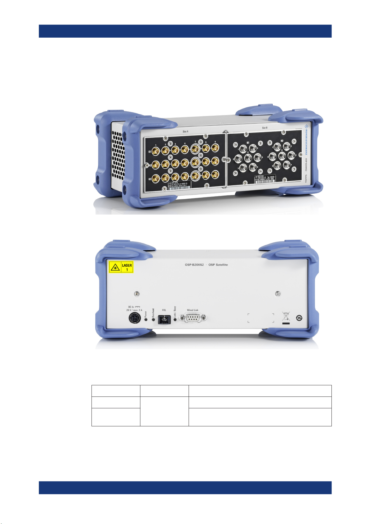
4.2 Satellite Unit R&S OSP-B200S2
The module R&S OSP-B200S2 is the satellite unit for the R&S OSP family. It offers two
slots for standard size (one-slot) switch modules:
Satellite Unit R&S
OSP-B200S2
Figure 4-3: Front view of R&S OSP-B200S2 satellite with two modules (R&S OSP-B128 and -B102)
Figure 4-4: Rear view of R&S OSP-B200S2 satellite unit with interface connectors, here model K04
Two versions of the R&S OSP-B200S2 satellite unit are available:
Model no. Description Characteristics
1528.3134K02 R&S OSP-B200S2
satellite unit
1528.3134K04 Fiber-optic and electrical interface (FOL and wired link).
Electrical interface (wired link)
Requires 28 V DC power supply R&S OSP-B200P.
For the meanings of the labels, see "Using laser products" on page 7 and Chapter 1.2,
"Labels on the Product", on page 8.
14User Manual 1178.6733.02 ─ 03

R&S®OSP-B200R/B200S2
Connectors in the R&S OSP-B200S2
Figure 4-5: Interface connectors and LEDs in the satellite unit's rear panel
DC In = Power input, only for FOL operation (far right: pin assignment)
FOL = Fiber-optic link, see Figure 5-5
Wired Link = DC interface, see Figure 5-4
Power, Overheat, Link/Busy = Status LEDs, see Table 6-1
Risk of equipment damage
Connect [Wired Link] to the R&S OSP-B200R remote control interface module, only.
Connecting it to any other equipment can cause damage.
Hardware Description
Accessories for the Satellite System
4.3 Accessories for the Satellite System
The following accessories are available for your satellite system applications:
Table 4-1: Accessories
Type Description Length Order no.
R&S OSP-Z200A LAN-type cable (wired link) with 15-pin D-Sub connectors on both ends.
R&S OSP-Z200B 10 m 1528.3170.04
R&S OSP-Z201A
R&S OSP-Z201B 10 m 1528.3186.04
R&S OSP-Z201C 20 m 1528.3186.06
R&S OSP-Z201D 30 m 1528.3186.08
R&S OSP-Z201E 40 m 1528.3186.10
R&S OSP-Z203XF
R&S OSP-Z203YF 1 m 1528.1690.03
R&S OSP-Z203ZF 3 m 1528.1690.04
R&S OSP-Z203AF 5 m 1528.1690.05
R&S OSP-Z203BF 10 m 1528.1690.10
R&S OSP-Z203CF 20 m 1528.1690.20
Used for direct connection of satellite and RC module.
Suited for K02 and K04 models.
Single-mode fiber-optic link (FOL) cable, yellow.
Suited for K04 models, only.
SC connectors on both ends.
Used for direct connection of satellite and RC module, only.
Multi-mode fiber-optic link (FOL) cable, orange.
Suited for K04 models, only.
SC connector on one end, FSMA connector on other end.
The delivery includes an FSMA-to-FSMA adapter.
Used for feedthrough via FSMA connection point (CP).
This usage requires two SC-FSMA cables.
5 m 1528.3170.02
5 m 1528.3186.02
0.5 m 1528.1690.02
15User Manual 1178.6733.02 ─ 03

R&S®OSP-B200R/B200S2
Hardware Description
Accessories for the Satellite System
Type Description Length Order no.
R&S OSP-Z203DF 30 m 1528.1690.30
R&S OSP-Z203EF 40 m 1528.1690.40
R&S OSP-Z204XF
R&S OSP-Z204YF 1 m 1528.1702.03
R&S OSP-Z204ZF 3 m 1528.1702.04
R&S OSP-Z204AF 5 m 1528.1702.05
R&S OSP-Z204BF 10 m 1528.1702.10
R&S OSP-Z204CF 20 m 1528.1702.20
R&S OSP-Z204DF 30 m 1528.1702.30
R&S OSP-Z204EF 40 m 1528.1702.40
R&S OSP-B200P
Multi-mode fiber-optic link (FOL) cable, orange.
Suited for K04 models, only.
FSMA connectors on both ends.
The delivery includes an FSMA-to-FSMA adapter.
Used as extension between two R&S OSP-Z203xF cables, or between multiple FSMA connection points.
Power supply, required only for satellite with FOL (model K04 of R&S OSP-B200S2).
Input: 90 VAC to 264 VAC, 47 Hz to 63 Hz, output: 28 V DC, max. 3.75 A.
0.5 m 1528.1702.02
1528.3205.02
The previously available R&S OSP-Z202xF single-mode FOL cables (yellow) are
replaced by the R&S OSP-Z203xF multi-mode FOL cables (orange) listed above.
Do not combine single-mode FOL cables with multi-mode FOL cables.
Figure 4-6: Available FOL cables for the K04 models of the satellite system
Z201x = SC-to-SC cable R&S OSP Z201x (yellow)
Z203xF = SC-to-FSMA cable R&S OSP Z203xF (orange), including FSMA-to-FSMA adapter
Z204xF = FSMA-to-FSMA cable R&S OSP Z204xF (orange), including FSMA-to-FSMA adapter
16User Manual 1178.6733.02 ─ 03

R&S®OSP-B200R/B200S2
5 Preparing for Use
● Unpacking and Checking........................................................................................ 17
● Mounting the RC Module into a Base Unit..............................................................17
● Mounting a Switch Module into the Satellite........................................................... 18
● Connecting the Satellite System's Components..................................................... 19
5.1 Unpacking and Checking
1. Unpack the product carefully.
2. Retain the original packing material. Use it when transporting or shipping the product later.
3. Using the delivery notes, check the equipment for completeness.
Preparing for Use
Mounting the RC Module into a Base Unit
4. Check the equipment for damage.
If the delivery is incomplete or equipment is damaged, contact Rohde & Schwarz.
5.2 Mounting the RC Module into a Base Unit
Mount the one-slot RC interface module R&S OSP-B200R into one of the R&S OSP
base switch units listed in Chapter 2, "Key Features", on page 10.
Figure 5-1: Remote-control interface module (here: model K04) mounted in base switch unit
Mounting a module is described in the user manuals of the base switch units.
We recommend connecting both interface cables of the R&S OSP-B200R to 2 internal
module busses on the R&S OSP mainboard, to enable using both slots in the satellite
unit, see Table 5-1.
A 1st-generation R&S OSP base unit provides 3 module busses. Typically, connect the
RC interface module to module buses A11 and A12. Note that you can operate only
one additional module in a 1st-generation base unit.
17User Manual 1178.6733.02 ─ 03

R&S®OSP-B200R/B200S2
5.3 Mounting a Switch Module into the Satellite
If you have ordered the satellite unit R&S OSP-B200S2 together with R&S OSP switch
modules, these modules are mounted and tested in the factory.
To mount a switch module in the satellite unit later on:
1. Disconnect all cables from the satellite unit.
2. For mounting your switch module, select a slot, A (left) and B (right), ideally covered by a blank panel.
If no blank panel is available, consider removing an existing module, instead.
3. Unscrew the six Torx 8 screws from the blank panel or existing module.
Keep the screws.
4. Remove the blank panel or existing module from the satellite unit.
5. Find the flat-ribbon cable (module bus cable) in the open slot of the satellite unit.
In each slot, one 26-pin flat-ribbon cable is available. Do not cross-over the cables.
Preparing for Use
Mounting a Switch Module into the Satellite
Figure 5-2: Satellite unit with slot B front panel removed
NOTICE! Avoid bad connector mating. The connector shape serves as protection
6.
against reversed (180° rotated) connector mating. See also "Risk of hardware
damage due to bad cable connection" in the base unit's user manual.
Connect the flat-ribbon cable to the switch module’s connector.
Figure 5-3: To attach or release the cable, press the latches on the sides of its connector
NOTICE! Avoid contact of open cable ends with conductive parts. During opera-
7.
tion, a short connection of open live cable ends with the satellite unit's casing can
18User Manual 1178.6733.02 ─ 03

R&S®OSP-B200R/B200S2
cause damage. See also "Risk of hardware damage due to open cable ends" in the
base unit's user manual.
Clamp any non-connected flat-ribbon cable in the satellite unit, with open cable
ends pointing away from the casing.
8. Carefully insert the switch module into the slot.
9. Fix the module with the six screws.
10. Reconnect the cables to the satellite unit.
5.4 Connecting the Satellite System's Components
For the overall satellite system, make the following interface connections:
●
Base unit to its integrated RC interface module R&S OSP-B200R, see Figure 5-1
●
RC interface module to satellite unit R&S OSP-B200S2
– By wired link as in Figure 5-4
– By FOL as in Figure 5-5
●
Only if you use FOL: power supply unit (28 V DC) to satellite unit as in Figure 5-5
●
Satellite unit to its integrated switch modules, see Figure 5-2
Preparing for Use
Connecting the Satellite System's Components
Table 5-1: Details of the satellite system connections
R&S OSP model Satellite
channel
1st generation
(R&S OSP120,
R&S OSP130,
R&S OSP150)
2nd generation
(R&S OSP220,
R&S OSP230,
R&S OSP320)
Base unit to RC module RC module to
A11 (X2) / A12 (X4) or A13 (X13) to
R&S OSP-B200R / X101
A
Default connection is A11 to X101
A11 (X2) / A12 (X4) or A13 (X13) to
R&S OSP-B200R / X100
B
Default connection is A12 to X100
M01 (X201) ... M16 (X216) to
R&S OSP-B200R / X101
A
Default connection is M01 to X101
M01 (X201) ... M16 (X216) to
R&S OSP-B200R / X100
B
Default connection is M02 to X100
satellite
Use either a
connection by
D-Sub cable
(wired link) or,
for K04 models
only, a fiberoptic connection (FOL)
Satellite unit to
switch module
R&S OSPB200S2 / X101
R&S OSPB200S2 / X100
R&S OSPB200S2 / X101
R&S OSPB200S2 / X100
● Satellite System with Wired Link.............................................................................20
● Satellite System with Fiber-Optic Link.....................................................................21
● Overview of Interface Connections......................................................................... 21
19User Manual 1178.6733.02 ─ 03

R&S®OSP-B200R/B200S2
5.4.1 Satellite System with Wired Link
Figure 5-4: Satellite system with wired link (DC), suitable for K02 and K04 models
For remote operation of the satellite unit across a distance of up to 10 m, use the cable
R&S OSP-Z200x (see Table 4-1).
Preparing for Use
Connecting the Satellite System's Components
Risk of equipment damage
Connect [Wired Link] to the R&S OSP-B200R remote control interface module, only.
Connecting it to any other equipment can cause damage.
In this configuration, the satellite unit R&S OSP-B200S2 is powered by the R&S OSP
base unit via the DC cable. The base unit can supply two switch modules in the satellite unit, each with a maximum of 0.8 A (at 28 V DC).
20User Manual 1178.6733.02 ─ 03

R&S®OSP-B200R/B200S2
5.4.2 Satellite System with Fiber-Optic Link
Figure 5-5: Satellite system with fiber-optic link (FOL, K04 models only) and DC power supply
For remote operation of the satellite unit at a longer distance or inside a shielded room,
use an FOL cable R&S OSP-Z201x or R&S OSP-Z203x and optionally with R&S OSP-
Z204x as extensions (see Table 4-1).
Preparing for Use
Connecting the Satellite System's Components
5.4.3 Overview of Interface Connections
Figure 5-6 provides an overview of the interface connections.
The figure shows both connection modes:
●
The dashed gray double arrow represents the Wired Link (D-Sub cable)
●
The solid black double arrow represents the FOL (fiber-optic cable)
However, make sure to use only one connection mode at a time, either [Wired Link] or
[FOL].
21User Manual 1178.6733.02 ─ 03

R&S®OSP-B200R/B200S2
Preparing for Use
Connecting the Satellite System's Components
Figure 5-6: Interface connections in the R&S OSP-B200R/B200S2 satellite system
22User Manual 1178.6733.02 ─ 03

R&S®OSP-B200R/B200S2
6 Operating the Satellite System
When the satellite system is correctly installed and interconnected, proceed as follows
before switching on the R&S OSP base unit:
To power up the satellite system
1. Connect the RC module R&S OSP-B200R to the satellite unit R&S OSP-B200S2.
2. In an FOL setup (Figure 5-5), connect the power supply R&S OSP-B200P to the
satellite unit.
3. Only then power up the R&S OSP base unit.
Once powered up, operate modules in the satellite unit as if installed in the base unit.
6.1 System Status
Operating the Satellite System
Power Consumption
After booting, 2 LEDs in the RC interface module R&S OSP-B200R and 3 LEDs in the
satellite unit R&S OSP-B200S2 indicate the system status as follows:
Table 6-1: Status LEDs
Device [Power] LED [Link / Busy] LED [Overheat] LED
●
RC
module
Satellite
unit
Green when
power is ON
Green when
power is ON
Continuously yellow when link between
remote interface and satellite is established
●
Flashing yellow during data transfer
●
Continuously yellow when link between RC
module and satellite is established
●
Flashing yellow during data transfer
If overheating occurs, indicated by a red [Overheat] LED in the satellite unit, it resets its
built-in modules automatically.
6.2 Power Consumption
Both the satellite system and the modules fitted within the satellite unit draw power
from the R&S OSP base switch units. However, the additional power consumption
required by the satellite system is relatively low:
--
●
Orange when fan
is switched on
●
Red if overheating
occurs
●
Max. 50 mA at 28 V
●
Max. 250 mA at 3.3 V
For power consumption data of the various modules, refer to the data sheet of the
R&S OSP.
Note that in FOL operation, the R&S OSP-B200P supplies power to the satellite unit
and its modules.
23User Manual 1178.6733.02 ─ 03

R&S®OSP-B200R/B200S2
7 Transporting, Storage and Disposal
7.1 Transporting
Packing
Use the original packaging material. It consists of antistatic wrap for electrostatic protection and packing material designed for the product.
If you do not have the original packaging, use similar materials that provide the same
level of protection.
Transport altitude
Unless otherwise specified in the data sheet, the maximum transport altitude without
pressure compensation is 4500 m above sea level.
Transporting, Storage and Disposal
Disposal
7.2 Storage
Protect the product against dust. Ensure that the environmental conditions, e.g. temperature range and climatic load, meet the values specified in the data sheet.
7.3 Disposal
Rohde & Schwarz is committed to making careful, ecologically sound use of natural
resources and minimizing the environmental footprint of our products. Help us by disposing of waste in a way that causes minimum environmental impact.
Disposing electrical and electronic equipment
A product that is labeled as follows cannot be disposed of in normal household waste
after it has come to the end of its service life. Even disposal via the municipal collection
points for waste electrical and electronic equipment is not permitted.
Figure 7-1: Labeling in line with EU directive WEEE
Rohde & Schwarz has developed a disposal concept for the eco-friendly disposal or
recycling of waste material. As a manufacturer, Rohde & Schwarz completely fulfills its
obligation to take back and dispose of electrical and electronic waste. Contact your
local service representative to dispose of the product.
24User Manual 1178.6733.02 ─ 03

R&S®OSP-B200R/B200S2
8 Maintenance
The product does not require regular maintenance. It only requires occasional cleaning. It is however advisable to check the nominal data from time to time.
If you use a fiber-optic link (FOL) with FSMA connectors, clean these connectors
according to Chapter 8.2, "Maintaining Flawless FOL Connections", on page 25.
8.1 Cleaning
How to clean the product is described in "Cleaning the product" on page 7.
Do not use any liquids for cleaning. Cleaning agents, solvents (thinners, acetone),
acids and bases can damage the front panel labeling, plastic parts and display.
Maintenance
Maintaining Flawless FOL Connections
8.2 Maintaining Flawless FOL Connections
In FOL operation of K04 models with FSMA fiber-optic connectors (R&S OSP-Z201x
cables), keep these connectors clean to prevent errors in the communication between
RC module and satellite unit.
●
Handle all FSMA connectors with great care.
●
If disconnected, always cover all open male and female connectors with end caps.
Quality of fiber-optic connections
Before mating two fiber-optic connectors, clean and inspect both connectors.
Even if a connector appears clean to the naked eye, it can be contaminated. Therefore, use a special microscope to inspect the fiber-optic connectors:
Figure 8-1: Microscopic images show degrees of soiling on the end face of a fiber-optic connector
(source: Rosenberger-OSI GmbH)
Left = Connector soiled with dust, unacceptable quality of connection
Center = Same connector after pre-cleaning with alcohol, still unacceptable
Right = Same connector after dry post-cleaning, good cleaning result
25User Manual 1178.6733.02 ─ 03

R&S®OSP-B200R/B200S2
Figure 8-2: Schematic view of two opposing fiber end faces with contamination
Blue = Fiber core, typical diameter is 50 µm
Red = Contamination in the contact area
Recommended cleaning equipment
●
Dedicated dry fiber cleaning wipes, cards, reels, or tape
●
Isopropyl or ethyl alcohol, 90% (vol.). Do not use other cleaning liquids, unless
explicitly suited for cleaning fiber-optic connectors.
To avoid absorption of water in a hygroscopic alcohol cleaning liquid, keep it in a
hermetically sealed bottle. Or use alcohol-moisturized wipes from sealed bags.
●
Ferrule cleaning sticks, diameter 2.5 mm, for fiber-connector end-face cleaning
●
Ultra-clean compressed air from a spray can (optional)
Maintenance
Maintaining Flawless FOL Connections
Recommended inspection equipment
●
Hand-held microscope for fiber-optic connectors, magnification at least 200:1
– We recommend using a video microscope, because it is inherently eye-safe.
– If you use a direct ocular microscope, ensure that no live signal is in the fiber.
Looking into a magnified live beam can damage your eye.
●
Optionally, feed the microscope's video output to a computer. Use image-analysis
software to check the cleaning results of your fiber-optic connectors.
To clean a fiber-optic connector
1. Remove the end cap from the connector.
2. If the connector's end face is open, gently clean it with a dry fiber wipe, card, reel
or tape.
To do so, follow the application instructions of your cleaning equipment.
If no instructions are available, apply a single linear swipe of the connector's end
face across a previously unused part of the cleaning surface.
3. If the connector's end face is inside a ferrule, gently clean it with a dry ferrule
cleaning stick.
To do so, follow the application instructions of your cleaning equipment.
If no instructions are available, insert a previously unused stick into the connector's
ferrule with low force. Carefully rotate the stick counter-clockwise by 4 to 5 revolutions. Remove the stick.
4. Gently clean each connector with an alcohol-moisturized cleaning tool.
To do so, follow the application instructions of your cleaning equipment.
26User Manual 1178.6733.02 ─ 03

R&S®OSP-B200R/B200S2
If no instructions are available, apply a small amount of alcohol to your cleaning
equipment. Proceed as described for dry cleaning (step 2 or step 3).
5. To remove alcohol and contamination from the connector's end face, repeat the dry
cleaning procedure.
Alternatively, blow the connectors dry with ultra-clean compressed air.
CAUTION! Risk of eye damage. If you inspect the cleaning result with a direct ocu-
6.
lar microscope, ensure that no live signal is in the fiber. Looking into a magnified
live beam can damage your eye.
Visually inspect the cleaning result in an eye-safe microscope (Figure 8-1).
Especially the region of the fiber core must meet criteria as specified by standard
IEC 61300-3-35.
7. If the connector is not clean, repeat the cleaning procedure.
8. Apply the entire cleaning procedure to the opposite connector, too.
9. Mate these two fiber-optic connectors.
10. Repeat the procedure for all connectors in a link.
Maintenance
Contacting Customer Support
11. Check this link for flawless fiber-optic communication.
8.3 Contacting Customer Support
Technical support – where and when you need it
For quick, expert help with any Rohde & Schwarz product, contact our customer support center. A team of highly qualified engineers provides support and works with you
to find a solution to your query on any aspect of the operation, programming or applications of Rohde & Schwarz products.
Contact information
Contact our customer support center at www.rohde-schwarz.com/support, or follow this
QR code:
Figure 8-3: QR code to the Rohde
&
Schwarz support page
27User Manual 1178.6733.02 ─ 03
 Loading...