


®
R&S
OSP
Open Switch and Control
Platform
Getting Started
(;ÜÕA2)
1178711702
Version 08

The R&S®OSP is a high-performance switch platform from Rohde & Schwarz. It
facilitates RF tests by eliminating the need to rearrange coaxial cable connections
repeatedly during measurements. Instead, the application-specific modules in the
base unit automatically switch the required signal paths.
This document describes the following R&S®OSP base units with firmware version 2.30 and later:
●
R&S®OSP220 Base Unit 2HU without Touchscreen (order no. 1528.3105.02)
●
R&S®OSP230 Base Unit 2HU with Touchscreen (order no. 1528.3105.03)
●
R&S®OSP320 Base Unit 3HU without Touchscreen (order no. 1528.3111.02)
●
R&S®OSP-B200S2 Satellite 2HU for Base Units (order no. 1528.3134.02/.04)
For all optionally available standard switch modules, refer to the user manual,
which is available for download at https://www.rohde-schwarz.com/product/osp-n
> Manuals
The software contained in this product uses several valuable open source software packages. For information, see the "Open Source Acknowledgment" document, which is available for download from the
R&S OSP product page at https://www.rohde-schwarz.com/product/osp-n > Firmware.
Rohde & Schwarz would like to thank the open source community for their valuable contribution to embedded computing.
© 2022 Rohde & Schwarz GmbH & Co. KG
Muehldorfstr. 15, 81671 Muenchen, Germany
Phone: +49 89 41 29 - 0
Email: info@rohde-schwarz.com
Internet: www.rohde-schwarz.com
Subject to change – data without tolerance limits is not binding.
R&S® is a registered trademark of Rohde & Schwarz GmbH & Co. KG.
Trade names are trademarks of the owners.
1178.7117.02 | Version 08 | R&S®OSP
In this manual, products from Rohde & Schwarz are indicated without the ® symbol, e.g. R&S®OSP is indicated as R&S OSP.

R&S®OSP
Contents
1 Safety and regulatory information....................................... 5
1.1 Korea certification class B...................................................................5
1.2 Safety instructions................................................................................6
1.3 Labels on the product.......................................................................... 8
1.4 Warning messages in the documentation..........................................9
1.5 Restrictions on opening a switch unit................................................ 9
1.6 Safety considerations for SSRs........................................................ 10
2 Key features......................................................................... 11
Contents
3 Documentation overview.................................................... 12
3.1 Getting started manual.......................................................................12
3.2 User manual........................................................................................ 12
3.3 Data sheets and brochures................................................................12
3.4 Service manual....................................................................................13
3.5 Printed safety instructions.................................................................13
3.6 Instrument security procedures........................................................ 13
3.7 Release notes, open source acknowledgment................................ 13
3.8 Application notes & cards, white papers, etc.................................. 13
3.9 Tutorials............................................................................................... 14
4 Preparing for use................................................................. 15
4.1 Lifting and carrying............................................................................ 15
4.2 Unpacking and checking....................................................................16
4.3 Choosing the operating site.............................................................. 16
4.4 Setting up the product........................................................................17
4.5 Accessory list......................................................................................19
3Getting Started 1178.7117.02 ─ 08

R&S®OSP
4.6 Considerations for test setups.......................................................... 19
4.7 Connecting to power.......................................................................... 21
4.8 Connecting to LAN............................................................................. 21
4.9 Connecting monitor, mouse and keyboard...................................... 22
4.10 Connecting RF cables........................................................................ 22
4.11 Connecting control cables.................................................................23
4.12 Switching on or off............................................................................. 23
4.13 Checking the installed modules........................................................ 25
4.14 Configuring the initial instrument settings...................................... 26
Contents
5 Instrument tour.................................................................... 27
5.1 Front panel view..................................................................................27
5.2 Rear panel view...................................................................................31
6 Trying out the switch unit................................................... 35
6.1 Manual and remote modes of operation...........................................35
6.2 User interface and functional elements............................................37
6.3 Main action buttons............................................................................ 40
6.4 Elements of the status bar................................................................. 41
6.5 Manual module operation: switching / selecting............................. 41
6.6 Contacting customer support............................................................44
4Getting Started 1178.7117.02 ─ 08

R&S®OSP
Safety and regulatory information
Korea certification class B
1 Safety and regulatory information
The product documentation helps you use the product safely and efficiently. Follow the instructions provided here and in the following chapters.
Intended use
The R&S OSP is designated for switching and control applications, including RF
switching, in industrial, administrative, and laboratory environments. Use the
R&S OSP only for its designated purpose.
Observe the operating conditions and performance limits stated in the data sheet.
Target audience
This document is targeted at all users, including installers, operators, and maintenance personnel.
Where do I find safety information?
Safety information is part of the product documentation. It warns you of potential
dangers and gives instructions on how to prevent personal injury or damage
caused by dangerous situations. Safety information is provided as follows:
●
In Chapter 1.2, "Safety instructions", on page 6. The same information is
provided in many languages as printed "Safety Instructions". The printed
"Safety Instructions" are delivered with the product.
●
Throughout the documentation, safety instructions are provided when you
need to take care during setup or operation.
1.1 Korea certification class B
이 기기는 가정용(B급) 전자파 적합기기로서 주로 가정에서 사용하는 것을 목적으
로 하며, 모든 지역에서 사용할 수 있습니다.
5Getting Started 1178.7117.02 ─ 08

R&S®OSP
Safety and regulatory information
Safety instructions
1.2 Safety instructions
Products from the Rohde & Schwarz group of companies are manufactured
according to the highest technical standards. To use the products safely, follow
the instructions provided here and in the product documentation. Keep the product documentation nearby and offer it to other users.
Use the product only for its intended use and within its performance limits. Intended use and limits are described in the product documentation such as the data
sheet, manuals and the printed "Safety Instructions". If you are unsure about the
appropriate use, contact Rohde & Schwarz customer service.
Using the product requires specialists or specially trained personnel. These users
also need sound knowledge of at least one of the languages in which the user
interfaces and the product documentation are available.
Never open the casing of the product. Only service personnel authorized by
Rohde & Schwarz are allowed to repair the product. If any part of the product is
damaged or broken, stop using the product. Contact Rohde & Schwarz customer
service at http://www.customersupport.rohde-schwarz.com.
Lifting and carrying the product
The maximum weight of the product is provided in the data sheet. To move the
product safely, you can use lifting or transporting equipment such as lift trucks
and forklifts. Follow the instructions provided by the equipment manufacturer.
Choosing the operating site
Only use the product indoors. The product casing is not waterproof. Water that
enters can electrically connect the casing with live parts, which can lead to electric shock, serious personal injury or death if you touch the casing. If
Rohde & Schwarz provides accessories designed for your product, e.g. a carrying
bag, you can use the product outdoors.
Unless otherwise specified, you can operate the product up to an altitude of
2000 m above sea level. The product is suitable for pollution degree 2 environments where nonconductive contamination can occur. For more information on
environmental conditions such as ambient temperature and humidity, see the
data sheet.
6Getting Started 1178.7117.02 ─ 08

R&S®OSP
Setting up the product
Always place the product on a stable, flat and level surface with the bottom of the
product facing down. If the product is designed for different positions, secure the
product so that it cannot fall over.
If the product has foldable feet, always fold the feet completely in or out to ensure
stability. The feet can collapse if they are not folded out completely or if the product is moved without lifting it. The foldable feet are designed to carry the weight of
the product, but not an extra load.
If stacking is possible, keep in mind that a stack of products can fall over and
cause injury.
If you mount products in a rack, ensure that the rack has sufficient load capacity
and stability. Observe the specifications of the rack manufacturer. Always install
the products from the bottom shelf to the top shelf so that the rack stands
securely. Secure the product so that it cannot fall off the rack.
Safety and regulatory information
Safety instructions
Connecting to power
The product is an overvoltage category II product. Connect the product to a fixed
installation used to supply energy-consuming equipment such as household
appliances and similar loads. Keep in mind that electrically powered products
have risks, such as electric shock, fire, personal injury or even death.
Take the following measures for your safety:
●
Before switching on the product, ensure that the voltage and frequency indicated on the product match the available power source. If the power adapter
does not adjust automatically, set the correct value and check the rating of the
fuse.
●
Only use the power cable delivered with the product. It complies with countryspecific safety requirements. Only insert the plug into an outlet with protective
conductor terminal.
●
Only use intact cables and route them carefully so that they cannot be damaged. Check the power cables regularly to ensure that they are undamaged.
Also ensure that nobody can trip over loose cables.
●
If the product needs an external power supply, use the power supply that is
delivered with the product or that is recommended in the product documentation or a power supply that conforms to the country-specific regulations.
●
Only connect the product to a power source with a fuse protection of maximum 20 A.
7Getting Started 1178.7117.02 ─ 08

R&S®OSP
Safety and regulatory information
Labels on the product
●
Ensure that you can disconnect the product from the power source at any
time. Pull the power plug to disconnect the product. The power plug must be
easily accessible. If the product is integrated into a system that does not meet
these requirements, provide an easily accessible circuit breaker at the system
level.
Cleaning the product
Use a dry, lint-free cloth to clean the product. When cleaning, keep in mind that
the casing is not waterproof. Do not use liquid cleaning agents.
Meaning of safety labels
Safety labels on the product warn against potential hazards.
Potential hazard
Read the product documentation to avoid personal injury or product damage.
Electrical hazard
Indicates live parts. Risk of electric shock, fire, personal injury or even death.
Hot surface
Do not touch. Risk of skin burns. Risk of fire.
Protective conductor terminal
Connect this terminal to a grounded external conductor or to protective ground. This
connection protects you against electric shock if an electric problem occurs.
1.3 Labels on the product
Labels on the casing inform about:
●
Personal safety, see "Meaning of safety labels" on page 8
●
Product and environment safety, see Table 1-1
●
Identification of the product, for example as in the top left of Figure 5-1
8Getting Started 1178.7117.02 ─ 08

R&S®OSP
Safety and regulatory information
Restrictions on opening a switch unit
Table 1-1: Labels regarding product and environment safety
Potential hazard
Read the product documentation to avoid personal injury or product damage.
China RoHS certification, certifies compliance with the Chinese government's regulation on the restriction of hazardous substances (RoHS).
Labeling in line with EN 50419 for disposal of electrical and electronic equipment after
the product has come to the end of its service life. See "Disposal" in the user manual.
1.4 Warning messages in the documentation
A warning message points out a risk or danger that you need to be aware of. The
signal word indicates the severity of the safety hazard and how likely it will occur
if you do not follow the safety precautions.
WARNING
Potentially hazardous situation. Could result in death or serious injury if not avoided.
CAUTION
Potentially hazardous situation. Could result in minor or moderate injury if not
avoided.
NOTICE
Potential risks of damage. Could result in damage to the supported product or to
other property.
1.5 Restrictions on opening a switch unit
Do not open an R&S OSP, to avoid personal injury and instrument damage.
●
If opening is required for mounting a module, let Rohde & Schwarz service
personnel mount this module.
●
If opening is not required, follow the mounting instructions in the user manual.
9Getting Started 1178.7117.02 ─ 08

R&S®OSP
Safety and regulatory information
Safety considerations for SSRs
1.6 Safety considerations for SSRs
Risk of injury and damage due to inappropriate SSR usage
At power loss, solid-state relays (SSRs) have no defined switching state. Hence,
other than an electromechanical monostable relay, if there is a malfunction (for
example, missing supply voltage), typically the SSR ports go to a high-impedance
state. But the relay does not actively switch off a connected load. This failure can
lead to a risk of personal injury and damage of equipment.
To prevent this risk, you must implement a dedicated concept for failsafe operation of your system in a competent manner.
Risk of damage due to inappropriate SSR usage
Solid-state relays (SSRs) are intended for high-frequency and high-speed switching, but their semiconductor elements are damaged easily by excess current, voltage peaks or a short circuit. Hence, inappropriate conditions or usage can damage SSRs or connected components and lead to associated problems.
To prevent this risk, avoid excess current, voltage peaks and short circuits.
Risk of SSR damage due to inappropriate operating conditions
Solid-state relays (SSRs) for RF applications are intended for switching low powers. To avoid damage due to overload, refer to the operating conditions according
to the data sheet.
Monostable vs. failsafe
Without power, a solid-state relay (SSR) quits operating as a switch:
●
It is in a non-defined high-impedance state
●
It does not have any stable switching state
Sometimes, SSRs are considered as behaving like a monostable relay. And the
term "monostable relay" is often considered to be equivalent with the term "failsafe relay". However, this interpretation is misleading.
For more information, refer to the user manual.
10Getting Started 1178.7117.02 ─ 08

R&S®OSP
Key features
2 Key features
The R&S OSP is a highly flexible, modular switch and control platform. Each
switch unit can be equipped with several application-specific switch modules.
The platform meets the requirements of diverse test scenarios in production, labs
and development environments. Scenarios range from desktop configurations for
laboratory measurements to complex, rack-integrated test systems.
The R&S OSP220/230/320 described in this manual are the second generation of
switch units from Rohde & Schwarz, replacing the R&S OSP120/130/150.
Outstanding key features are:
●
5 to 10 module slots and up to 16 module buses provide maximum flexibility
●
Fast setup of test and measurement configurations
●
Replace complex wirings by a single switch and control platform
●
Easy interconnection configuration of primary and secondary switch units
●
Optional installation of several remotely controlled satellite units (see p. 29)
●
Reliable measurements and reproducible tests
●
Automation for cost-efficient test sequences
●
Electromechanical relay modules up to 67 GHz
●
Solid-state relay modules with switching and settling times down to the µs
range
●
Backward compatible to all standard modules of the previous switch unit generation R&S OSP120/130/150, as described in the user manual
The available switch modules are described in the user manual.
For a detailed specification of the R&S OSP, refer to the data sheet, available for
download at www.rohde-schwarz.com/brochure-datasheet/osp-n.
Note that switch units are no measurement instruments. They support efficient working with test and measurement setups, but switch units do not display measurement results or power levels.
11Getting Started 1178.7117.02 ─ 08

R&S®OSP
Documentation overview
Data sheets and brochures
3 Documentation overview
This section provides an overview of the R&S OSP user documentation. Unless
specified otherwise, you find the documents on the R&S OSP product page at:
www.rohde-schwarz.com/product/osp-n
3.1 Getting started manual
Introduces the R&S OSP and describes how to set up and start working with it.
Includes, e.g., basic operations and safety instructions. A printed version is delivered with the switch unit. A PDF version is available for download on the Internet.
3.2 User manual
Contains the description of all switch unit modes and functions. It also provides
an introduction to remote control, a complete description of the remote control
commands with programming examples, and information on maintenance, interfaces and error messages. Includes the contents of the getting started manual.
A separate R&S OSP-B200R/B200S2 Satellite System user manual is also available for download at www.rohde-schwarz.com/manual/osp-n.
3.3 Data sheets and brochures
The data sheet contains the technical specifications of the R&S OSP. It also lists
the firmware applications and their order numbers, and optional accessories.
The brochure provides an overview of the instrument and deals with the specific
characteristics.
See www.rohde-schwarz.com/brochure-datasheet/osp-n
If there is a data mismatch between the data sheet and other documentation, the
information given in the data sheet is valid.
12Getting Started 1178.7117.02 ─ 08

R&S®OSP
Application notes & cards, white papers, etc.
Documentation overview
3.4 Service manual
Describes handling failed modules, module replacement, troubleshooting and
special remote control commands for service purposes. The document also contains spare part lists and mechanical drawings. The service manual ("Classified
Service Document") is available for Rohde & Schwarz personnel, only.
3.5 Printed safety instructions
Provides safety information in many languages. The printed document is delivered with the product.
3.6 Instrument security procedures
Deals with security issues when working with the R&S OSP in secure areas. It is
available for download on the Internet.
3.7 Release notes, open source acknowledgment
The release notes list new features, improvements and known issues of the current firmware version, and describe the firmware installation. The open-source
acknowledgment document (OSA) provides verbatim license texts of the used
open-source software. See www.rohde-schwarz.com/firmware/osp-n
3.8 Application notes & cards, white papers, etc.
These documents deal with special applications or background information on
particular topics. See www.rohde-schwarz.com/application/osp and www.rohde-
schwarz.com/application/osp-n.
13Getting Started 1178.7117.02 ─ 08

R&S®OSP
Also, we recommend reading the application note "Guidance on Selecting and
Handling Coaxial RF Connectors", which is available on the Internet at
www.rohde-schwarz.com/appnote/1MA99.
Documentation overview
Tutorials
3.9 Tutorials
Tutorials offer guided examples and demonstrations on operating the R&S OSP.
They are provided on the product page of the internet.
14Getting Started 1178.7117.02 ─ 08

R&S®OSP
Preparing for use
Lifting and carrying
4 Preparing for use
Here, you can find basic information about setting up the product for the first time.
● Lifting and carrying..........................................................................................15
● Unpacking and checking................................................................................. 16
● Choosing the operating site............................................................................ 16
● Setting up the product..................................................................................... 17
● Accessory list.................................................................................................. 19
● Considerations for test setups.........................................................................19
● Connecting to power....................................................................................... 21
● Connecting to LAN.......................................................................................... 21
● Connecting monitor, mouse and keyboard......................................................22
● Connecting RF cables.....................................................................................22
● Connecting control cables...............................................................................23
● Switching on or off...........................................................................................23
● Checking the installed modules...................................................................... 25
● Configuring the initial instrument settings....................................................... 26
4.1 Lifting and carrying
See "Lifting and carrying the product" on page 6.
The R&S OSP has protruding handles at the left and right of its front panel. Each
handle is designed to carry the weight of the switch unit. Also, the handles provide some mechanical protection for the front panel.
Figure 4-1: Handles (1) for lifting and carrying the R&S OSP. Underneath: foldable feet (2)
15Getting Started 1178.7117.02 ─ 08

R&S®OSP
Choosing the operating site
Preparing for use
4.2 Unpacking and checking
1. Unpack the product carefully.
2. Retain the original packing material. Use it when transporting or shipping the
product later.
3. Using the delivery notes, check the equipment for completeness.
4. Check the equipment for damage.
If the delivery is incomplete or equipment is damaged, contact
Rohde & Schwarz.
4.3 Choosing the operating site
Specific operating conditions ensure proper operation and avoid damage to the
product and connected devices. For information on environmental conditions
such as ambient temperature and humidity, see the data sheet.
See also "Choosing the operating site" on page 6.
Electromagnetic compatibility classes
The electromagnetic compatibility (EMC) class indicates where you can operate
the product. The EMC class of the product is given in the data sheet.
●
Class B equipment is suitable for use in:
– Residential environments
– Environments that are directly connected to a low-voltage supply network
that supplies residential buildings
●
Class A equipment is intended for use in industrial environments. It can cause
radio disturbances in residential environments due to possible conducted and
radiated disturbances. It is therefore not suitable for class B environments.
If class A equipment causes radio disturbances, take appropriate measures to
eliminate them.
16Getting Started 1178.7117.02 ─ 08

R&S®OSP
Preparing for use
Setting up the product
4.4 Setting up the product
See also "Intended use" on page 5 and "Setting up the product" on page 7.
4.4.1 Placing the product on a bench top
To place the product on a bench top
1. Place the product on a stable, flat and level surface. Ensure that the surface
can support the weight of the product. For information on the weight, see the
data sheet.
2. CAUTION! Foldable feet can collapse. See "Setting up the product"
on page 7.
Always fold the feet completely in or out. With folded-out feet, do not place
anything on top or underneath the product.
3. WARNING! A stack of products can fall over and cause injury. Never stack
more than three products on top of each other. Instead, mount them in a rack.
Stack as follows:
● If the products have foldable feet, fold them in completely.
● It is best if all products have the same dimensions (width and length). If the
products have different dimensions, stack according to size and place the
smallest product on top.
● Do not exceed the permissible total load placed on the product at the bot-
tom of the stack:
– 50 kg when stacking products of identical dimensions (left figure).
– 25 kg when stacking smaller products on top (middle figure).
17Getting Started 1178.7117.02 ─ 08

R&S®OSP
Preparing for use
Setting up the product
Left = Stacked correctly, same dimensions
Middle = Stacked correctly, different dimensions
Right = Stacked incorrectly, too many products
4. NOTICE! Overheating can damage the product.
Prevent overheating as follows:
● Keep a minimum distance of 10 cm between the fan openings of the prod-
uct and any object in the vicinity.
● Do not place the product next to heat-generating equipment such as radia-
tors or other products.
4.4.2 Mounting the product in a rack
Note that the satellite unit R&S OSP-B200S2 is not designed for rack-mounting.
To prepare the rack
1. Observe the requirements and instructions in "Setting up the product"
on page 7.
2. NOTICE! Insufficient airflow can cause overheating and damage the product.
Design and implement an efficient ventilation concept for the rack.
To mount the product in a 19'' rack
1. Use an adapter kit to prepare the product for rack mounting.
a) Order the rack adapter kit designed for the product:
● For 2 HU (R&S OSP220 and R&S OSP230), use R&S ZZA-KNA21
(order no. 1177.8026.00)
● For 3 HU (R&S OSP320), use R&S ZZA-KNA31 (order no.
1177.8032.00)
b) Mount the adapter kit. Follow the assembly instructions provided with the
adapter kit.
2. Grab the R&S OSP by its handles (Figure 4-1).
3. Insert it onto the shelf until the rack brackets fit closely to the rack.
4. Tighten all screws on the rack brackets, typically with a torque of 4.6 Nm, to
secure the product in the rack.
18Getting Started 1178.7117.02 ─ 08

R&S®OSP
Preparing for use
Considerations for test setups
To unmount the product from a rack
1. Loosen the screws at the rack brackets.
2. Remove the product from the rack.
3. If placing the product on a bench top again, unmount the adapter kit from the
product. Follow the instructions provided with the adapter kit.
4.5 Accessory list
The R&S OSP base unit comes with the following accessories:
●
Printed "Getting Started" manual, English (order no. 1178.7117.02)
●
Ethernet (LAN) cable, 2 m, RJ45 (1:1), category 6 (order no. 0041.9748.00)
●
Power supply cable, delivered country-specific to fit your local wall outlet format, see Table 4-1
Table 4-1: Power cords
Power supply cables according to country-specific standards Order no.
European standard
Angular adapter for European standard
British standard 0006.7013.00
Swiss standard 0006.7020.00
US American standard 0006.7036.00
Australian standard 0006.7107.00
Chinese standard 0041.4752.00
Japanese standard 0041.6232.00
Brazilian standard 3587.8102.00
0025.2365.00
0086.4400.44
4.6 Considerations for test setups
Preventing electrostatic discharge (ESD)
Electrostatic discharge is most likely to occur when you connect or disconnect a
DUT.
19Getting Started 1178.7117.02 ─ 08

R&S®OSP
Considerations for test setups
► NOTICE! Electrostatic discharge can damage the electronic components of
the product and the device under test (DUT).
Ground yourself to prevent electrostatic discharge damage:
a) Use a wrist strap and cord to connect yourself to ground.
b) Use a conductive floor mat and heel strap combination.
A risk of damage due to ESD is typically limited to switch units that are equipped
with modules that have one or more of the following features:
●
Digital input or output ports (I/O ports)
●
Solid-state relays (SSR)
●
Integrated amplifiers in special modules that are delivered as part of a test
system
Preventing electromagnetic interference (EMI)
Preparing for use
Electromagnetic interference (EMI) can affect the measurement results.
To suppress electromagnetic radiation during operation:
●
Use high-quality shielded cables, for example, double-shielded RF, LAN and
HDMI cables.
Note: USB cables are of varying and often poor quality. Therefore, consider
the quality of each individual USB cable.
●
Always terminate open cable ends.
●
Note the EMC classification in the data sheet.
●
Ensure that connected external devices comply with EMC regulations.
Preventing overload on internal terminations
Overloading an electromechanical RF relay with internal port termination can
damage or destroy the relay.
The maximum load that the internal termination of one port can handle is approximately 1 W. However, if the relay has several terminated ports, their cumulative
maximum load is less than the sum. For example, an SP6T relay with 6 internally
terminated ports cannot handle 6 W, but typically 3 W, only.
To avoid the risk of damage due to overloading internal terminations, limit the load
to the "Max. termination power per relay" that is specified in the data sheet.
20Getting Started 1178.7117.02 ─ 08

R&S®OSP
Preparing for use
Connecting to LAN
4.7 Connecting to power
The switch unit is equipped with an AC power supply connector and can be used
with different AC voltages. The R&S OSP adapts itself automatically to the voltage. Refer to the data sheet for the voltage and frequency requirements. The AC
power connector is on the rear panel of the switch unit.
► Connect the R&S OSP to an AC power supply using the supplied power
cable.
As the switch unit's assembly is in line with the specifications for safety class
EN61010, you must connect it only to an outlet that has a ground contact.
For replacing the fuses, refer to the maintenance chapter in the user manual.
4.8 Connecting to LAN
The LAN connector (RJ45) of the R&S OSP is on its rear panel, shown in Fig-
ure 6-4.
Network environment
Before connecting the product to a local area network (LAN), consider the following:
●
Install the latest firmware, as described in the user manual, to reduce security
risks.
●
For internet or remote access, use secured connections if applicable.
For example, use HTTPS, SFTP, FTPS instead of HTTP, FTP.
●
Ensure that the network settings comply with the security policies of your company. Contact your local system administrator or IT department before connecting your product to your company LAN.
●
When connected to the LAN, the product may potentially be accessed from
the internet, which may be a security risk. For example, attackers might misuse or damage the product.
For more information on how to connect the switch unit to the LAN, and for the IP
address, refer to the user manual.
21Getting Started 1178.7117.02 ─ 08

R&S®OSP
Preparing for use
Connecting RF cables
4.9 Connecting monitor, mouse and keyboard
The HDMI and USB connectors for an external monitor, a mouse and a keyboard
are on the front panel of the R&S OSP, shown in Figure 6-4.
For connecting these devices, refer to the user manual.
4.10 Connecting RF cables
Many modules are desigened for connecting test equipment via RF cables.
Excessive tightening of coaxial RF connections can damage the connectors of
both cables and modules. Too weak tightening leads to inaccurate measurement
results.
Connecting RF cables / TORQUE RECOMMENDATIONS
For best connections, proceed as follows:
1. Carefully align the connectors along a common axis.
2. Mate the connectors along the common axis until the male pin of the inner
connector engages with the female socket of the outer connector.
3. When fastening the connectors, only turn the nut of the outer connector until
the connectors are firmly coupled.
Avoid rotating the body of the outer connector.
4. If the inner connector is on a cable, hold it stationary with a spanner.
5. For fastening the connection, use a calibrated torque wrench suitable for the
connector type.
Never use a standard open-end wrench.
6. Fasten the nut of the outer connector to the specified torque.
For specifications, refer to application note 1MA99, which is available on the
Internet at www.rohde-schwarz.com.
For N, SMA and PC connectors, we recommend applying the following torque:
● 150 N·cm for N connectors
● 56 N·cm for SMA connectors (standard, PTFE-filled)
● 90 N·cm for PC connectors (3.5 mm / 2.92 mm / 2.4 mm / 1.85 mm, air-
filled)
22Getting Started 1178.7117.02 ─ 08

R&S®OSP
Preparing for use
Switching on or off
Rohde & Schwarz offers torque wrenches for various connectors. For ordering
information, also refer to the application note 1MA99
7. Note that 3.5 & 2.92 mm PC connectors are incompatible with 2.4 & 1.85
mm PC connectors.
4.11 Connecting control cables
Many modules are desigened for connecting test equipment via control cables.
Typically, these connections are straight forward and require no precautions.
However, take special care in the following cases:
●
In I/O modules (input / output), avoid overloading the digital input lines. The
maximum voltage to be applied directly to the input connectors is TTL level:
standard 3.3 V DC, tolerating up to 5 V DC. For voltages > 5 V DC up to
28 V DC, insert a resistor in series with a minimum resistance of 22 kΩ.
●
In the satellite system, use the [Wired Link] connectors only for connecting
the remote control module R&S OSP-B200R with the satellite unit R&S OSPB200S2. Connecting a [Wired Link] connector to any other device's connector
can damage your equipment.
See Chapter 5.2.4, "Rear panel of the R&S OSP-B200S2 satellite unit",
on page 33.
4.12 Switching on or off
Table 4-2: Overview of power states
Status LED above [Pwr] key Position of rear power switch
Off Off [0]
Standby
Ready
orange
green
[I]
[I]
To switch on the R&S OSP
The product is off but connected to power.
► Set the AC power switch on the rear panel to position [I].
23Getting Started 1178.7117.02 ─ 08

R&S®OSP
The instrument is supplied with AC power. After booting, the instrument is
ready for operation. A green LED above the [Pwr] key on the front panel indicates the operating mode.
To shut down the R&S OSP
1. NOTICE! Risk of data loss. See "How to avoid losing settings" on page 24.
Check the LED above the [Pwr] key on the front panel (labeled 7 in Fig-
ure 6-4).
Preparing for use
Switching on or off
● If the LED emits orange light
The switch unit is already in standby mode.
● Otherwise, if the LED emits green light , set the switch unit to standby
mode by pressing the [Pwr] key.
The LED changes from green to orange light, indicating standby mode.
The switch unit is now unavailable via LAN, even if connected.
2. Optionally, set the AC power switch on the rear panel to position [O].
The R&S OSP changes into off mode.
To disconnect from power
1. Shut down the switch unit.
2. Disconnect it from the power source.
How to avoid losing settings
While the R&S OSP is in operating mode, if you switch it off using the rear panel
switch or by disconnecting the power cord, the instrument loses its current settings. (Operating mode is indicated by a green LED above the [Pwr] key.)
, do not press the [Pwr] key.
For example, if you have selected signal paths previously, you must select and
enable these paths again, when you restart the switch unit.
To avoid a loss of settings, press the [Pwr] key first to set the switch unit into
standby mode. Then shut it down properly by setting the rear AC power switch to
position [O].
●
If "Configuration" > "General" > "Switch-On Reset" is activated, the R&S OSP
resets all internal latching switches during the startup procedure.
●
If "Configuration" > "General" > "Switch-On Action" is set to "Switch Path", the
R&S OSP loads the previously set path while booting. The switch unit activates this path when the startup procedure is completed.
24Getting Started 1178.7117.02 ─ 08

R&S®OSP
Checking the installed modules
Display timeout
The OLED status display of a switch unit R&S OSP220 or R&S OSP320
serves for showing you the network connection. The LAN connection is set
typically at power-up.
The status display switches off automatically after setting the LAN connection with a timeout specified by the "Status Display Period" parameter in the
"General" configuration tab (see user manual). Without a network connection, the status display switches off with the same timeout after power-up.
This feature helps to prevent burn-in effects often seen in OLED displays.
When the switch unit is connected via a new network address, the status
display is switched on again for the next 30 minutes. (Your server can
assign a new address, for example, when you change the switch unit's network settings from static IP to DHCP, as described in the user manual.)
The RGB-LED touchscreen display in the R&S OSP230 and in the module
R&S OSP-B300M needs no burn-in protection. Thus, it has no timeout.
Preparing for use
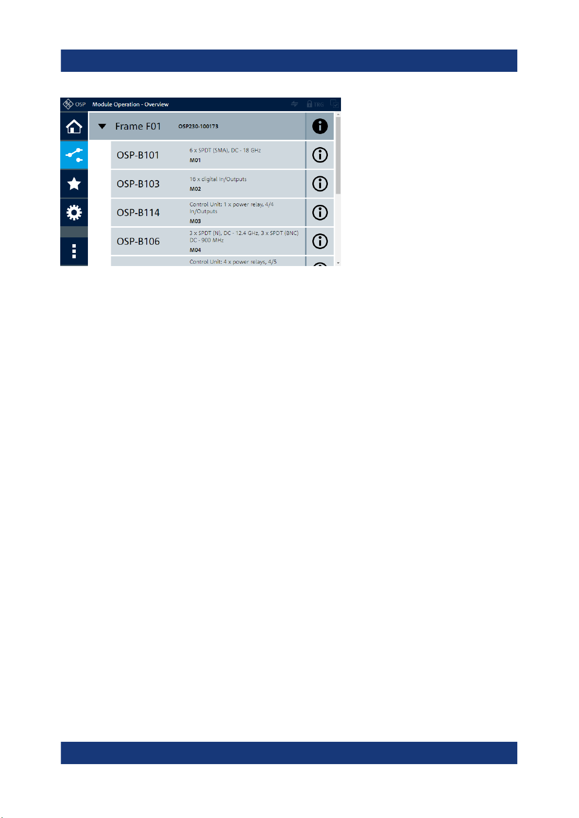
4.13 Checking the installed modules
The instrument is typically equipped with one or more optional switch modules.
You can visually check whether the modules listed on your delivery note correspond with the installed modules. Each module's name is printed on its panel.
You can also view the installed modules in the "Module Operation" dialog (touchscreen display or "WebGUI", see Chapter 6.2, "User interface
and functional elements", on page 37):
25Getting Started 1178.7117.02 ─ 08
R&S®OSP
Configuring the initial instrument settings
Figure 4-2: The module operation dialog, here with a single switch unit and 5 modules
The information in this dialog is updated during the booting process, when the
R&S OSP automatically detects the installed modules.
Preparing for use
4.14 Configuring the initial instrument settings
After startup, the switch unit is fully configured automatically, and ready for use.
However, you have many options to change the configuration, for example:
●
Edit the network settings
●
Define or modify an interconnection setup
●
Restore a previous setting
●
Define switching paths and output channels
These configuration settings and many more, for example for a setup of primary
and secondary switch units, are described in the user manual.
26Getting Started 1178.7117.02 ─ 08

R&S®OSP
Instrument tour
Front panel view
5 Instrument tour
● Front panel view..............................................................................................27
● Rear panel view.............................................................................................. 31
5.1 Front panel view
The following chapters describe the front panels of all models of the R&S OSP
switch unit family. For the functional elements, refer to Chapter 6.2.
5.1.1 Front panel of the R&S OSP220
The front panel of the R&S OSP220 features 3 module slots, a monochrome nontouch status display, a power switch and various connectors.
The R&S OSP220 occupies 2 height units (2HU) in a standard 19" rack. You can
insert 1-slot, 2-slot or 3-slot modules into the 3 front slots:
Figure 5-1: Front view of the R&S OSP220 (2HU)
FS01 = Front slot 01, here with a blind plate
FS02 = Front slot 02, here with a 1-slot switch module
FS03 = Front slot 03, here with a blind plate
F Int = Front interfaces and status display (OLED, 128 x 64 pixels), see Figure 6-4
5.1.2 Front panel of the R&S OSP230
The front panel of the R&S OSP230 features 2 module slots, an integrated touchscreen display, a power switch and various connectors.
27Getting Started 1178.7117.02 ─ 08

R&S®OSP
Instrument tour
Front panel view
The R&S OSP230 occupies 2 height units (2HU) in a standard 19" rack. You can
insert two 1-slot modules or one 2-slot module into the 2 front slots:
Figure 5-2: Front view of the R&S OSP230 (2HU)
FS01 = Front slot 01, here with a blind plate
FS02 = Front slot 02, here with a 1-slot switch module
Disp. = Integrated touchscreen display (and no front slot 03)
F Int = Front interfaces, see Figure 6-4
5.1.3 Front panel of the R&S OSP320
The R&S OSP320 is higher than all other switch units from Rohde & Schwarz.
With its 3 height units (3HU), it enables a more dense fitting of 1-slot switch modules within the same instrument width. Hence, its front panel features 5 module
slots, along with a power switch, a status display and various connectors.
2 of the 5 front slots (labeled FS04 and FS05 in Figure 5-3) can hold the factorymounted optional touchscreen display module R&S OSP-B300M:
Figure 5-3: Front view of the R&S OSP320 (3HU)
28Getting Started 1178.7117.02 ─ 08

R&S®OSP
Instrument tour
Front panel view
FS01 to FS03 = Front slots 01 to 03, here each with a 1-slot switch module
FS04 + FS05 = Front slot 04 and 05, here with mounted touchscreen display module
F Int = Front interfaces and status display (OLED, 128 x 64 pixels), see Figure 6-4
The dedicated touchscreen display module R&S OSP-B300M shown in Fig-
ure 5-3 is optional (see p. 30). It can only be factory-mounted in the
R&S OSP320 with 3 height units (3HU) in position FS04 + FS05.
You cannot insert any modules into the R&S OSP320 that are designed as 2-slot
or 3-slot modules for a switch unit with 2 height units (2HU, see above).
5.1.4 Front panel of the R&S OSP-B200S2 satellite unit
For a comprehensive description of this unit, also refer to the R&S OSP-
B200R/B200S2 Satellite System user manual, available for download at
www.rohde-schwarz.com/manual/osp-n.
The R&S OSP-B200S2 is a standalone device, only, not to be mounted into a 19"
rack. The front panel of satellite unit the features 2 module slots, into which you
can insert 1-slot or 2-slot modules:
Figure 5-4: Front view of the R&S OSP-B200S2 (2HU)
SlotA = Front slot A, here with a 1-slot switch module
SlotB = Front slot B, here with a 1-slot switch module
This unit is designed to serve as a satellite with up to 2 switch modules, controlled
from a base switch unit with remote control module R&S OSP-B200R.
29Getting Started 1178.7117.02 ─ 08

R&S®OSP
For example, you can use the satellite unit inside a shielded chamber for EMC
tests that do not tolerate electrical wiring. In this scenario, use the satellite with
local battery power supply, and control the switch modules fitted in the unit via a
fiber-optic link. See also Chapter 5.2.4.1, "Wired link versus fiber-optic link",
on page 34.
Instrument tour
Front panel view
5.1.5 Touchscreen
Figure 5-5: Touchscreen display, here showing the Main menu
●
The R&S OSP230 is equipped with an integrated touchscreen display on the
front panel.
●
The R&S OSP320 can be equipped with the touchscreen display module
R&S OSP-B300M.
Touch the screen gently with your fingers or use a stylus pen with a smooth soft
tip.
For instructions on cleaning the screen, see the Maintenance chapter in the
R&S OSP user manual.
Both the integrated display and the display module are based on a touch-sensitive RGB LCD with a resolution of 800 x 480 pixels.
The touchscreen display offers one out of several means of user interaction for
easily handling the switch unit. It shows the relay and switch-path settings, provides status information and allows configuring and controlling your measurement
tasks.
The touchscreen reacts in a defined way when you tap a particular
element on the screen with a finger or with a pointing device, for
example an external USB mouse. Any user interface element that
reacts to a click by a mouse pointer also reacts to a tap on the screen, and vice
versa. Using the touchscreen, you can perform all tasks by the tap of your finger.
30Getting Started 1178.7117.02 ─ 08

R&S®OSP
Instrument tour
Rear panel view
For the remainder of this manual, all interactions are described for a "click" action.
These descriptions also mean the equivalent "tap" action using the touchscreen.
On-screen keyboard
The on-screen keyboard is an additional means of direct interaction with the
switch unit R&S OSP230 or R&S OSP320, the latter if equipped with touchscreen
module R&S OSP-B300M.
Figure 5-6: Different versions of the on-screen keyboard
Left = Numbers and characters allowed
Center = Decimal numbers, only
Right = Hexadecimal numbers
The touchscreen automatically opens an on-screen keyboard, if your current
action requires entering numbers or characters. The cancel button or the OK button closes the on-screen keyboard.
Instead of using the on-screen keyboard, you can enter data with a connected
external keyboard (Figure 6-1) or via the user interface in a browser (Figure 6-2).
5.2 Rear panel view
The following chapters describe the rear panels of all models of the R&S OSP
switch unit family. For the functional elements, refer to Chapter 6.2.
The meanings of the labels on the product are described in Chapter 1.3, "Labels
on the product", on page 8.
5.2.1 Rear panel of the R&S OSP220
The rear panel of the R&S OSP220 features 3 module slots, an on/off switch,
fuses, power supply connector, LAN and USB connectors and a micro SD card
slot. You can insert 1-slot, 2-slot or 3-slot modules into the 3 rear slots:
31Getting Started 1178.7117.02 ─ 08
R&S®OSP
Instrument tour
Rear panel view
Figure 5-7: Rear view of the R&S OSP220 (2HU)
R Int = Rear interfaces, see Figure 6-4
RS01 to RS03 = Rear slots 01 to 03, here each with a blind plate
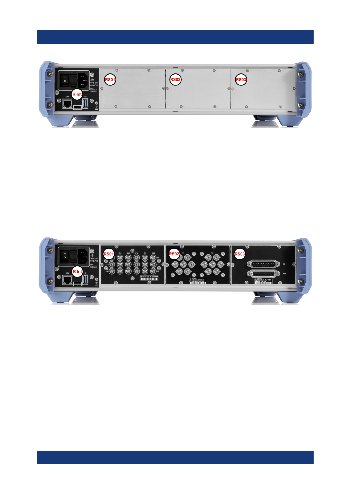
5.2.2 Rear panel of the R&S OSP230
The rear panel of the R&S OSP230 features 3 module slots, an on/off switch,
fuses, power supply connector, LAN and USB connectors and a micro SD card
slot. You can insert 1-slot, 2-slot or 3-slot modules into the 3 rear slots:
Figure 5-8: Rear view of the R&S OSP230 (2HU)
R Int = Rear interfaces, see Figure 6-4
RS01 to RS03 = Rear slots 01 to 03, here each with a 1-slot switch module
5.2.3 Rear panel of the R&S OSP320
The rear panel of the R&S OSP320 features 5 module slots, an on/off switch,
fuses, power supply connector, LAN and USB connectors and a micro SD card
slot:
32Getting Started 1178.7117.02 ─ 08

R&S®OSP
Instrument tour
Rear panel view
Figure 5-9: Rear view of the R&S OSP320 (3HU)
R Int = Rear interfaces, see Figure 6-4, with an additional D-Sub 9 trigger connector
RS01 to RS05 = Rear slots 01 to 05, here each with a 1-slot switch module
You cannot insert any modules into the R&S OSP320 that are designed as 2-slot
or 3-slot modules for a switch unit with 2 height units (2HU, see above).
The D-Sub 9 trigger connector (next to the label "R Int" in Figure 5-9) is only
available in the rear interface panel of the R&S OSP320, not in any other
switch unit. This connector enables the addressed hardware trigger.
5.2.4 Rear panel of the R&S OSP-B200S2 satellite unit
For a comprehensive description of this unit, also refer to the R&S OSP-
B200R/B200S2 Satellite System user manual, available for download at
www.rohde-schwarz.com/manual/osp-n.
The rear panel of the R&S OSP-B200S2 features various connectors and LEDs.
You cannot insert any modules into the rear panel of the R&S OSP-B200S2.
33Getting Started 1178.7117.02 ─ 08

R&S®OSP
Figure 5-10: Rear view of the R&S OSP-B200S2 (2HU)
1 = DC power supply connector
2 = Fiber-optic link (FOL) connector for optical remote control
3 = Wired link connector for electrical remote control
4 = Status LEDs for indicating [Power] and [Overheat]
5 = Status LED for indicating [Link / Busy]
Instrument tour
Rear panel view
5.2.4.1 Wired link versus fiber-optic link
The link connectors (labeled 2 and 3 in Figure 5-10) allow choosing either an
electrical or an optical control connection.
●
Wired link
For remote operation of the satellite unit R&S OSP-B200S2 across distances
up to 10 m, use the D-Sub cable R&S OSP-Z200x.
Connect this cable exclusively to the remote control interface module
R&S OSP-B200R in your base switch unit. Connecting it to any other device
or module can harm your equipment.
The wired link cable supplies power from the base switch unit to the satellite.
●
Fiber-optic link
For remote operation of the satellite unit R&S OSP-B200S2 across larger distances up to 20 m, or inside a shielded room, use the fiber-optic cable
R&S OSP-Z201x or R&S OSP-Z202x.
As the fiber-optic link cable does not supply power to the satellite unit, you
must also use the 28 V DC power supply R&S OSP-B200P.
34Getting Started 1178.7117.02 ─ 08

R&S®OSP
Manual and remote modes of operation
Trying out the switch unit
6 Trying out the switch unit
This chapter introduces the most important basic operations and settings of the
R&S OSP step by step. For a complete overview, see the user manual (p. 12).
Prerequisite: the instrument is set up, connected to mains power supply and started up, as described in Chapter 4 on page 15. The next sections describe:
● Manual and remote modes of operation......................................................... 35
● User interface and functional elements...........................................................37
● Main action buttons......................................................................................... 40
● Elements of the status bar.............................................................................. 41
● Manual module operation: switching / selecting..............................................41
● Contacting customer support.......................................................................... 44
6.1 Manual and remote modes of operation
You can operate the switch unit by any of the following modes:
● Direct manual operation.................................................................................. 35
● Manual remote operation................................................................................ 36
● Remote operation by SCPI commands...........................................................36
6.1.1 Direct manual operation
If you use an R&S OSP230 or an R&S OSP320 with display module R&S OSPB300M, you can control your switch unit by the user interface on the integrated
touchscreen display.
Alternatively, with any of the R&S OSP models, you can control your switch unit
via an external mouse and keyboard, connected to the USB interfaces (see 4 in
Figure 6-4). Optionally (especially without integrated touchscreen), you can con-
nect an external monitor to the switch unit's HDMI interface (see 5).
35Getting Started 1178.7117.02 ─ 08

R&S®OSP
Trying out the switch unit
Manual and remote modes of operation
Figure 6-1: Operation by integrated touchscreen (1) or by external USB / HDMI devices (2)
For scrolling the touchscreen, swipe it with your finger. With an external
monitor, click and use the mouse wheel or the keyboard's up/down keys.
For connecting external devices, see Figure 6-4.
6.1.2 Manual remote operation
You can control one or more switch units by working with the user interface in a
web browser ("WebGUI") on a remote computer that is connected via LAN.
Figure 6-2: Manual remote operation via "WebGUI" and LAN
RJ45 = Ethernet (LAN) connector on the rear panel of each switch unit
Refer to the user manual for more information, also regarding the combination of
several switch units in "Interconnection" mode.
Note that the legacy software R&S OSP Panel is not compatible with the
switch units R&S OSP220, R&S OSP230 and R&S OSP320.
6.1.3 Remote operation by SCPI commands
You can control the R&S OSP by SCPI commands sent from a remote computer
that is connected via LAN. Refer to the user manual.
36Getting Started 1178.7117.02 ─ 08

R&S®OSP
Trying out the switch unit
User interface and functional elements
Figure 6-3: Remote operation by SCPI commands
RJ45 = Ethernet (LAN) connector on the rear panel of each switch unit
Far left = Two switch units integrated in a test system like R&S CEMS
To do so, you have the following options:
●
For SCPI command communication, use a terminal program like R&S Forum
or similar programming interface (for example with R&S VISA driver). Remote
operation and RC commands are described in the user manual.
●
Use your own application to communicate with the R&S OSP via a VISA interface or directly via a TCP/IP raw socket connection.
●
Let a test system software like R&S EMC32 or R&S ELEKTRA send the
required commands. Refer to www.rohde-schwarz.com/product/emc32 and
www.rohde-schwarz.com/product/elektra.
The R&S OSP can handle up to 5 open SCPI command connections simultaneously.
6.2 User interface and functional elements
The switch units R&S OSP220 and
The switch unit R&S OSP230 and the display module R&S OSP-B300M have a
touchscreen display.
Its functions are described in the user manual.
R&S OSP320 have a status display.
After booting, it displays the hostname, IP
address, subnet mask and device status information. For details, refer to the user manual.
See also "Display timeout" on page 25.
You cannot operate the switch units R&S OSP220 ‒ and the R&S OSP320 without display module R&S OSP-B300M ‒ by their status displays. To operate these
37Getting Started 1178.7117.02 ─ 08

R&S®OSP
Trying out the switch unit
User interface and functional elements
switch units without the graphical user interface of a built-in full touchscreen display, use one of the following alternatives:
●
As on the right-hand side in Figure 6-1, connect an external monitor to the
HDMI connector on the unit's front panel (labeled 5 in Figure 6-4). Also connect a mouse and keyboard to the USB connectors, labeled (4).
●
Use the switch unit as a secondary device in interconnection mode, as described in the user manual.
●
Connect the switch unit to a local area network (LAN) by the RJ45 connector
on the unit's rear panel. The connector is labeled (1) in Figure 6-4. Read the
unit's IP address from the status display and proceed as described in Chap-
ter 6.1.2, "Manual remote operation", on page 36, or Chapter 6.1.3, "Remote
operation by SCPI commands", on page 36.
Figure 6-4: Connectors and functional elements on the switch unit's rear and front panel
R = Rear interfaces (where the R&S OSP320 has an additional trigger port, see Figure 5-9)
F = Front interfaces (where the R&S OSP230 has no OLED status display, see Chapter 6, "Try-
ing out the switch unit", on page 35)
I/0 = Main power switch with fuse holder and power connector
1 = LAN connector (RJ45)
2 = Slot for the micro SD card that holds the switch unit's operating system
3 = USB 3.1 connector
4 = Two USB 2.0 connectors (for external mouse and keyboard)
5 = HDMI connector (for an external monitor)
6 = Two BNC trigger input connectors (A and B, with two trigger status LEDs), see below
7 = Front power switch with [Pwr] and LAN status LEDs
38Getting Started 1178.7117.02 ─ 08

R&S®OSP
Trying out the switch unit
User interface and functional elements
If you connect an external monitor to the HDMI connector (5), use a monitor
that is compatible with this port’s DVI signal. This signal is configured for the
touchscreen's resolution of 800 x 480 pixels. Incompatible monitors cannot
display the graphical user interface.
With the trigger connectors (6), the R&S OSP is prepared for external triggering, which requires the hardware trigger option R&S OSP-K100. Firmware versions below version 2.00 do not support this trigger option.
Note that the rear interface panel of the R&S OSP320 has an additional DSub 9 trigger connector, as shown in Figure 5-9.
In any of these configurations, you can operate a switch unit by its user interface:
either on an external monitor or in a web browser (we recommend using Chrome
as browser). The same holds true for the R&S OSP230 and R&S OSP320 with
integrated display module R&S OSP-B300M, which allow touchscreen operation.
Using any of these options, you get access to the graphical user interface (GUI):
Figure 6-5: Main menu of the graphical user interface ("WebGUI"), here in the recommen-
ded Chrome browser
In the "Main" menu of the user interface, clicking the "Help" icon in the
top-right area opens an overview of the available functions:
39Getting Started 1178.7117.02 ─ 08

R&S®OSP
Trying out the switch unit
Main action buttons
Figure 6-6: Main elements of the graphical user interface (GUI)
1 = Main menu
2 = Module operation
3 = Path switching
4 = Device configuration
5 = Context menu, always used together with one of the menu buttons above
6 = Status bar with varying elements, see Chapter 6.4
The main GUI elements listed above are briefly described in Chapter 6.3, "Main
action buttons", on page 40, and Chapter 6.4, "Elements of the status bar",
on page 41. For more information, refer to the user manual.
6.3 Main action buttons
The user interface includes the following main action buttons:
The "Main" menu provides status and network information. Its context
menu (1)+(5) gives additional device info and messages.
The "Module Operation" dialog allows immediate interaction with the
relays. For a brief overview, see Chapter 6.5.
The "Path Switching" dialog allows defining, editing and activating
paths. You can also export and import paths.
The "Configuration" dialog allows configuring the general settings, the
trigger system (optional), the network settings and the interconnection
setup.
40Getting Started 1178.7117.02 ─ 08

R&S®OSP
Manual module operation: switching / selecting
Context Menu
The "Context Menu" button calls specific functionality for any of the
menu items shown above and listed as (1) to (4) in Figure 6-6. Hence,
this button is always used together with one of the other buttons.
For more information, refer to the user manual.
Trying out the switch unit
6.4 Elements of the status bar
The status bar is shown on top in Figure 6-5 and Figure 6-6.
The various indicator icons have the following meanings:
Left: the R&S OSP is controlled by its graphical user interface
(locally or via LAN). Right: the R&S OSP is controlled
remotely by SCPI commands or a primary device. See Chapter 6.1, "Manual and
remote modes of operation", on page 35.
If this label is displayed in the status bar, the R&S OSP is in virtual
mode (see user manual).
If the lock icon is highlighted (right), it indicates the locked mode (see
user manual).
If the trigger icon is highlighted (right), the software option R&S OSP-
K100 is enabled and the trigger is activated (see user manual).
If the selection indicator icon is highlighted (right), at least one
relay or output channel is selected (see Chapter 6.5.2).
6.5 Manual module operation: switching / selecting
This chapter outlines only the most basic features of the dialogs for manual "Module Operation" that allow immediate interaction with the relays.
Click the "Module Operation" button
modules or to open the interaction dialog of one switch module:
to see a list of all installed switch
41Getting Started 1178.7117.02 ─ 08

R&S®OSP
Trying out the switch unit
Manual module operation: switching / selecting
Table 6-1: Left overview: list of modules in virtual mode. / Right: interaction dialog of one
module in physical mode.
If you see the interaction dialog of one switch module (as in the right picture above), click the "Module Operation" button . You see the list of
installed modules (as in the left picture above, here a screenshot in virtual mode). In the icon of the "Module Operation" button, the "back" arrow (available with firmware versions from 1.40) indicates that it brings you back to the list.
To see the interaction dialog of any module, click its name in the list.
6.5.1 Switching mode
Allows switching the state of relays and output channels.
Switching mode is active, if the selection mode (see Chapter 6.5.2) is deactivated. In switching mode, clicking the icon of a switchable item changes its state:
Figure 6-7: Various relay types and the effect of clicking them
●
(A) SPDT relays, and (B) DPDT relays: Clicking toggles the state
●
(C) SP6T relays, and (D) SP8T relays (or SPxT relays):
Clicking a terminal port selects it to be connected to the common port
●
(E) Output channels: Clicking toggles the state
42Getting Started 1178.7117.02 ─ 08
R&S®OSP
Trying out the switch unit
Manual module operation: switching / selecting
For switching relays, output channels or other switchable items, the "Selection"
button (orange, described below) must not be active.
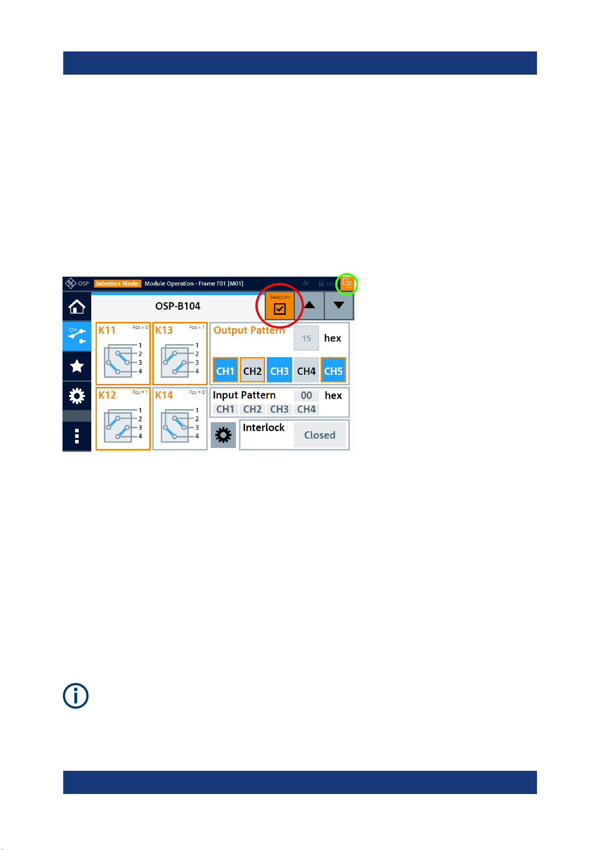
6.5.2 Selection mode
Allows selecting relays and output channels.
The "Selection" button switches the "Selection Mode" on or off. This button
(marked by a red circle in Figure 6-8) is only available in a view that shows at
least one module and its details.
Figure 6-8: Relay or channel selection dialog
Red circle = If the "Selection" button (mouse-over: "Toggle select mode") is orange, the
"Selection Mode" is activated, also indicated by the name color of the selectable
items changing from black to orange.
Green circle = "Items selected" indicator. The icon is highlighted, if at least one relay or output
channel in any module is selected.
Orange
frames
= Selected relays and output channels are highlighted in the module's interaction
dialog
While the "Selection Mode" is active, tapping or clicking the icon of a relay, output
channel or other Switchable items does not change its state, but only selects or
deselects it. This selection is indicated by the icon's name and frame color
changing from gray to orange.
Use the selection mode for defining paths and output patterns. To select or
deselect all relays and output channels, go to "Module Operation" (or "Path
Switching") > "Context Menu" > "Path Selection" > "Select All" or "Deselect
All".
43Getting Started 1178.7117.02 ─ 08
R&S®OSP
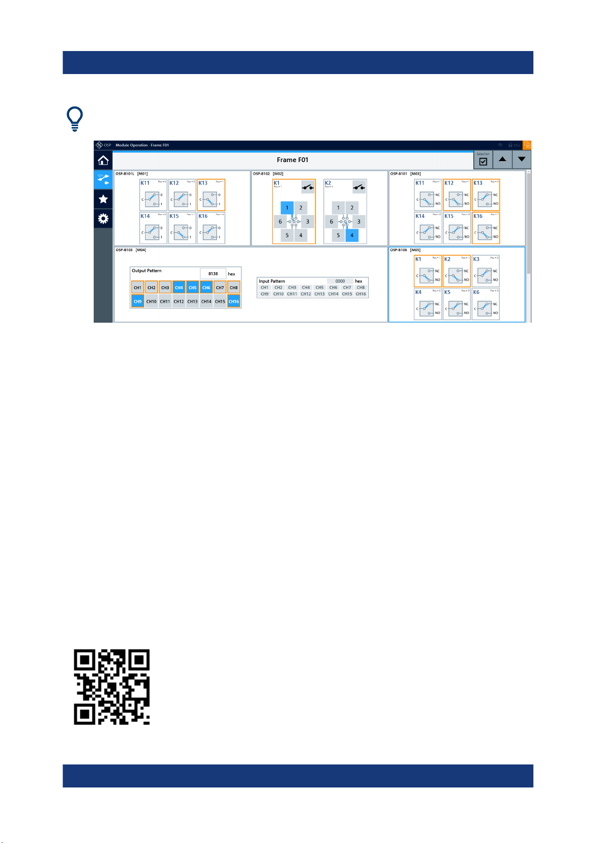
In a full-screen window of your web browser, the module interaction dialog
can display several modules at the same time:
Figure 6-9: Full-screen representation of several modules in a browser window
Trying out the switch unit
Contacting customer support
On the contrary, to reproduce the original size of the touchscreen display,
set your browser window to 800 × 480 pixels. Optionally, press [F12] to
enter this setting.
For a comprehensive description of module operation and all other functions,
including the definition and switching of paths, refer to the user manual.
6.6 Contacting customer support
For quick, expert help with any Rohde & Schwarz product, contact our customer
support center. A team of highly qualified engineers provides support and works
with you to find a solution to your query on any aspect of the operation, programming or applications of Rohde & Schwarz products. Contact our customer support
center at www.rohde-schwarz.com/support, or follow this QR code:
44Getting Started 1178.7117.02 ─ 08
 Loading...