


PAD-T-M: 3574.3259.02
/01.00
/CI/1/EN
R&S®OSP
Open Switch and Control Unit
Operating Manual
1505.3896.12 – 17
Operating Manual
Test and Measurement

The Operating Manual describes the following R&S®OSP models and options:
● R&S®OSP120, stock no. 1505.3009.02/.12
● R&S®OSP130, stock no. 1505.3009.03
● R&S®OSP150, stock no. 1505.3009.05/.15
● Option Module R&S®OSP-B011, stock no. 1505.4763.02
● Option Module R&S®OSP-B012, stock no. 1505.4770.02
● Option Module R&S®OSP-B101, stock no. 1505.5101.02
● Option Module R&S®OSP-B101L, stock no. 1505.5101.52
● Option Module R&S®OSP-B102, stock no. 1505.5201.02
● Option Module R&S®OSP-B102L, stock no. 1505.5201.52
● Option Module R&S®OSP-B103, stock no. 1505.5301.02
● Option Module R&S®OSP-B104, stock no. 1505.5401.02
● Option Module R&S®OSP-B106, stock no. 1505.5601.02
● Option Module R&S®OSP-B107, stock no. 1505.5901.02
● Option Module R&S®OSP-B108, stock no. 1505.5718.02
● Option Module R&S®OSP-B111, stock no. 1505.4605.02
● Option Module R&S®OSP-B111UL, stock no. 1528.1531.13/.16
● Option Module R&S®OSP-B111VL, stock no. 1515.5991.13/.16
● Option Module R&S®OSP-B112, stock no. 1505.4611.02
● Option Module R&S®OSP-B112UL, stock no. 1528.1548.11
● Option Module R&S®OSP-B114, stock no. 1505.4711.02
● Option Module R&S®OSP-B116, stock no. 1515.5827.02
● Option Module R&S®OSP-B116H, stock no. 1515.5827.40
● Option Module R&S®OSP-B119, stock no. 1515.5856.02
● Option Module R&S®OSP-B121, stock no. 1515.5504.02
● Option Module R&S®OSP-B121H, stock no. 1515.5504.40
● Option Module R&S®OSP-B122, stock no. 1515.5510.02
● Option Module R&S®OSP-B122H, stock no. 1528.1525.02
● Option Module R&S®OSP-B123, stock no. 1515.5527.02
● Option Module R&S®OSP-B124, stock no. 1515.5533.02
● Option Module R&S®OSP-B125, stock no. 1515.5540.02
● Option Module R&S®OSP-B125E/H, stock no. 1515.5540.26/.40
● Option Module R&S®OSP-B126, stock no. 1515.5556.02
● Option Module R&S®OSP-B127, stock no. 1505.4728.02
● Option Module R&S®OSP-B128, stock no. 1505.4734.02
● Option Module R&S®OSP-B129, stock no. 1517.7004.02
● Option Module R&S®OSP-B131, stock no. 1505.4740.02
● Option Module R&S®OSP-B132, stock no. 1505.4757.02
● Option Module R&S®OSP-B133, stock no. 1528.3157.02
● Option Module R&S®OSP-B136, stock no. 1522.4500.02
● Option Module R&S®OSP-B142, stock no. 1528.1048.03/.11/.12/.13
● Option Module R&S®OSP-B149H, stock no. 1528.3234.02
● Option Module R&S®OSP-B158, stock no. 4094.7300.02
The software contained in this product uses several valuable open source software packages. For information,
see the "Open Source Acknowledgment" on the user documentation CD-ROM (included in delivery) or at
https://www.rohde-schwarz.com/en/firmware/osp.
Rohde & Schwarz would like to thank the open source community for their valuable contribution to embedded computing.
© 2018 Rohde & Schwarz GmbH & Co. KG
Muehldorfstr. 15, 81671 Munich, Germany
Phone: +49 89 41 29 - 0
Fax: +49 89 41 29 12 164
E-mail: info@rohde-schwarz.com
Internet: http://www.rohde-schwarz.com/
Subject to change – Data without tolerance limits is not binding.
R&S® is a registered trademark of Rohde & Schwarz GmbH & Co. KG.
Trade names are trademarks of the owners.
The following abbreviations are used throughout this manual:
R&S®OSP is abbreviated as R&S OSP

R&S OSP Contents
Operating Manual 1505.3896.12 - 17 3
Contents
1 Documentation Overview ................................................................. 13
2 Preparing for Use .............................................................................. 15
2.1 Front Panel Tour R&S OSP120 .................................................................................15
2.1.1 Status LEDs and Standby Key ....................................................................................16
2.1.2 Front Panel Connectors ...............................................................................................16
2.2 Front Panel Tour R&S OSP130 .................................................................................17
2.2.1 Navigation Keys ...........................................................................................................18
2.2.2 Status Keys ..................................................................................................................18
2.2.3 Status Indicators ..........................................................................................................18
2.2.4 Front Panel USB Connectors ......................................................................................19
2.3 Front Panel Tour R&S OSP150 .................................................................................19
2.4 Rear Panel Tour .........................................................................................................19
2.4.1 LAN Connector ............................................................................................................20
2.4.2 CAN Bus Connector.....................................................................................................21
2.4.3 Mains Switch and Connector .......................................................................................21
2.5 Putting the Instrument into Operation .....................................................................22
2.5.1 Unpacking the Instrument and Checking the Shipment ..............................................22
2.5.2 Instrument Setup..........................................................................................................23
2.5.3 Bench Top Operation ...................................................................................................23
2.5.4 Mounting in a 19" Rack ................................................................................................23
2.5.5 EMI Protective Measures .............................................................................................23
2.5.6 Connecting the Instrument to the AC Supply ..............................................................24
2.5.7 Power on and off ..........................................................................................................24
2.5.8 Replacing Fuses ..........................................................................................................24
2.5.9 Standby and Ready State ............................................................................................25
2.6 Maintenance ...............................................................................................................25
2.6.1 Storing and Packing .....................................................................................................26
2.7 Connecting External Accessories ............................................................................26
2.7.1 Connecting a USB Flash Drive ....................................................................................26
2.7.2 Connecting a Keyboard ...............................................................................................26
2.7.3 Connecting a Monitor ...................................................................................................27
2.7.4 Connecting a LAN Cable .............................................................................................27
2.8 Starting the R&S OSP and Shutting Down ..............................................................28
2.9 Remote Operation in a LAN ......................................................................................28
2.9.1 Assigning an IP Address ..............................................................................................28

R&S OSP Contents
Operating Manual 1505.3896.12 - 17 4
2.9.2 R&S OSP Panel ...........................................................................................................31
2.10 Linux Operating System ...........................................................................................31
2.10.1 Keyboard Properties ....................................................................................................32
2.11 Firmware Update ........................................................................................................32
2.12 Read the actual Firmware Version ...........................................................................34
2.12.1 Get Firmware Version using R&S OSP Panel .............................................................34
2.12.2 Get Firmware Version via SCPI Command .................................................................35
3 Getting Started .................................................................................. 36
3.1 Connecting R&S OSP and PC ..................................................................................37
3.2 Installing the R&S OSP Panel ...................................................................................38
3.3 R&S OSP Panel Functions ........................................................................................38
3.3.1 Configuring/Connecting R&S OSP Panel ....................................................................39
3.3.2 Addressing R&S OSP Device ......................................................................................41
3.3.3 Changing the IP address with R&S OSP Panel ..........................................................43
3.3.4 General Actions of R&S OSP Panel ............................................................................44
3.3.5 Addressing R&S OSP Modules ...................................................................................45
3.3.6 Controlling the R&S OSP-B101/-B106/-B107/-B111/-B127/-B132 ..............................46
3.3.7 Controlling the R&S OSP-B102/-B112/-B122/-B126/-B128 ........................................47
3.3.8 Controlling the R&S OSP-B125 ...................................................................................50
3.3.9 Controlling the R&S OSP-B103/-B158 ........................................................................51
3.3.10 Controlling the R&S OSP-B104/-B114 ........................................................................54
3.3.11 Controlling the R&S OSP-B108 ...................................................................................58
3.3.12 Controlling the R&S OSP-B131 ...................................................................................59
3.3.13 Controlling the R&S OSP-B116/-B136 ........................................................................59
3.3.14 Controlling the R&S OSP-B142 ...................................................................................60
3.3.15 Controlling the R&S OSP-B149H ................................................................................61
3.4 Path Configuration.....................................................................................................62
3.4.1 Save a Path .................................................................................................................63
3.4.2 Switch a Path ...............................................................................................................65
3.4.3 Delete a Path ...............................................................................................................65
3.4.4 Export a Path ...............................................................................................................66
3.4.5 Import a Path ...............................................................................................................68
3.5 Sample Session .........................................................................................................69
3.5.1 Example Path Configuration ........................................................................................69
3.5.2 Manual Setting of the Paths .........................................................................................73
3.5.3 Remote Control Setting of the Path Configuration ......................................................74
3.6 Path Configuration in virtual mode ..........................................................................75
3.6.1 Simulated Module Configuration ..................................................................................75

R&S OSP Contents
Operating Manual 1505.3896.12 - 17 5
3.6.2 Path Configuration .......................................................................................................76
3.6.3 Import of Path Configuration ........................................................................................77
3.7 GUI Info Line ...............................................................................................................77
3.7.1 Configuring the GUI Info Line ......................................................................................78
4 Manual Operation ............................................................................. 80
4.1 Manual Operation of the Modules ............................................................................80
4.2 R&S OSP Setups ........................................................................................................80
5 Instrument Functions ....................................................................... 81
5.1 R&S OSP Instrument Frame .....................................................................................81
5.1.1 R&S OSP Block Diagram ............................................................................................82
5.1.2 R&S OSP Module Slots ...............................................................................................84
5.1.3 R&S OSP120 Version12 and Module Slots .................................................................84
5.1.4 R&S OSP120 Version12 and Modules R&S OSP-B011/-B012 ..................................85
5.1.5 R&S OSP150 Version15 and Module Slots .................................................................87
5.1.6 R&S OSP150 Version15 and Modules R&S OSP-B011/-B012 ..................................89
5.2 Module Functions ......................................................................................................89
5.2.1 RF Switch Module R&S OSP-B101/-B107/-B111/-B127 .............................................89
5.2.2 RF Switch Module R&S OSP-B102/-B112/-B128 ........................................................90
5.2.3 I/O Module R&S OSP-B103 .........................................................................................92
5.2.4 I/O Module R&S OSP-B104 .........................................................................................94
5.2.5 RF Switch Module R&S OSP-B106/-B132 ..................................................................96
5.2.6 DC MUX Module R&S OSP-B108 ...............................................................................97
5.2.7 RF Switch Module R&S OSP-B121 and R&S OSP-B121H ........................................98
5.2.8 RF Switch Modules R&S OSP-B122, OSP-B122H and OSP-B133 ............................99
5.2.9 RF Switch Module R&S OSP-B123 and R&S OSP-B124 .........................................100
5.2.10 RF Switch Module R&S OSP-B125 and R&S OSP-B126 .........................................103
5.2.11 Module R&S OSP-B114 for EMS application ............................................................105
5.2.12 RF Switch Module R&S OSP-B131 ...........................................................................107
5.2.13 RF Switch Module R&S OSP-B129 and R&S OSP-B119 .........................................108
5.2.14 Power Sensor Module R&S OSP-PM-I......................................................................110
5.2.15 RF Switch Module R&S OSP-B116/-B116H and R&S OSP-B136 ............................111
5.2.16 RF Switch Module R&S OSP-B101L/-B111xL and R&S OSP-B102L/-B112UL .......112
5.2.17 I/O and supply Module R&S OSP-B158 ....................................................................113
5.2.18 RF Switch Module R&S OSP-B142 ...........................................................................115
5.2.19 RF Switch Module R&S OSP-B149H ........................................................................116
5.3 Graphical User Interface .........................................................................................117
5.3.1 Starting the R&S OSP120 .........................................................................................117
5.3.2 Starting the R&S OSP130 .........................................................................................120

R&S OSP Contents
Operating Manual 1505.3896.12 - 17 6
5.3.3 General Navigation Operations .................................................................................121
5.3.4 Using the R&S OSP-B101/-B106/-B107/-B111 .........................................................123
5.3.5 Using the R&S OSP-B102/-B112 ..............................................................................125
5.3.6 Using the R&S OSP-B103 .........................................................................................126
5.3.7 Using the R&S OSP-B104 .........................................................................................127
5.3.8 Using the R&S OSP-B121 .........................................................................................129
5.3.9 Using the R&S OSP-B122 and OSP-B133 ................................................................129
5.3.10 Using the R&S OSP-B123 to R&S OSP-B126 and R&S OSP-B129 ........................130
5.3.11 Path Configuration .....................................................................................................131
5.4 R&S OSP Switch Cycle Counter .............................................................................135
5.5 R&S OSP Selftest .....................................................................................................137
5.5.1 Selftest via R&S OSP Panel ......................................................................................137
5.6 R&S OSP Configuration Check ..............................................................................137
5.6.1 System Info via R&S OSP Panel ...............................................................................137
5.7 SCPI Read/Write .......................................................................................................138
5.7.1 R&S OSP Temperature Read Command ..................................................................139
6 Remote Control ............................................................................... 141
6.1 Remote Control Operation ......................................................................................141
6.1.1 Establishing and Testing a LAN Connection .............................................................142
6.1.2 Switchover to Remote Control ...................................................................................143
6.1.3 Return to Manual Operation ......................................................................................143
6.2 Messages ..................................................................................................................143
6.2.1 VXI-11 Interface Messages .......................................................................................143
6.2.2 Device Messages (Commands and Device Responses) ..........................................144
6.2.3 SCPI Command Structure and Syntax ......................................................................144
6.3 The R&S OSP Command Processing ....................................................................148
6.3.1 Input Unit ....................................................................................................................148
6.3.2 Command Recognition ..............................................................................................149
6.3.3 Data Base and Instrument Hardware ........................................................................149
6.3.4 Status Reporting System ...........................................................................................149
6.3.5 Output Unit .................................................................................................................150
6.4 Status Reporting System ........................................................................................150
6.4.1 Overview of Status Registers ....................................................................................151
6.4.2 Contents of the Status Registers ...............................................................................151
6.4.3 Application of the Status Reporting System ..............................................................153
6.4.4 Reset Values of the Status Reporting System ..........................................................155
7 Remote Command Reference ........................................................ 156

R&S OSP Contents
Operating Manual 1505.3896.12 - 17 7
7.1 Special Terms and Notation ...................................................................................156
7.2 Naming Conventions ...............................................................................................157
7.3 Common Commands ...............................................................................................159
7.4 Instrument-Control Commands ..............................................................................161
7.4.1 ROUTe Commands ...................................................................................................161
7.4.2 READ Commands......................................................................................................167
7.4.3 CONFigure Commands .............................................................................................171
7.4.4 MMEMory Commands ...............................................................................................172
7.4.5 DIAGnostic Commands .............................................................................................174
7.4.6 SYSTem Commands .................................................................................................175
7.5 Alphabetical List of Commands (System) .............................................................181
8 Applications .................................................................................... 182
8.1 R&S OSP and R&S EMC32 Software .....................................................................182
8.1.1 Configuration of the R&S EMC32 for R&S OSP ........................................................182
8.1.2 Defining the R&S OSP Properties in the R&S EMC32 ..............................................184
8.1.3 Setting the R&S OSP with the R&S EMC32 ..............................................................185
8.1.4 Interlock Functionality with R&S EMC32 ...................................................................185
8.2 R&S OSP Drivers .....................................................................................................188
8.3 Extending the R&S OSP System ............................................................................189
8.3.1 R&S OSP150 Extension Unit .....................................................................................189
8.3.2 Connecting the R&S OSP150 ....................................................................................190
8.3.3 How to Register the R&S OSP150 ............................................................................191
8.4 Application of Module R&S OSP-B103 ..................................................................192
8.4.1 Controlling External Relays with R&S OSP-B103 .....................................................192
8.4.2 Input Ports of R&S OSP-B103 ...................................................................................195
8.4.3 Output Ports of R&S OSP-B103 ................................................................................196
8.5 Application of Module R&S OSP-B104 ..................................................................196
8.5.1 Controlling External Power Relays with R&S OSP-B104 ..........................................196
8.5.2 Interlock Monitoring with the R&S OSP-B104 ...........................................................197
8.5.3 Input Ports of R&S OSP-B104 ...................................................................................198
8.5.4 Output Ports of R&S OSP-B104 ................................................................................199
8.6 Application of Module R&S OSP-B114 ..................................................................199
8.6.1 Switching a Signal Generator via the R&S OSP-B114 module .................................200
8.6.2 Interlock Circuitry with the R&S OSP-B114 Module ..................................................201
8.6.3 I/O Ports on the R&S OSP-B114 Module ..................................................................202
8.7 Application of Module R&S OSP-B158 ..................................................................203
8.7.1 Controlling active antennas with R&S OSP-B158 .....................................................203

R&S OSP Contents
Operating Manual 1505.3896.12 - 17 8
9 Appendix ......................................................................................... 205
9.1 Interfaces and Connectors .....................................................................................205
9.1.1 Front Panel Connectors .............................................................................................205
9.1.2 Rear Panel Connectors .............................................................................................205
9.1.3 LAN Interface .............................................................................................................207
9.2 R&S OSP Module Interfaces ...................................................................................209
9.2.1 R&S OSP-B101/-B107/-B111/-B127 Interface ..........................................................209
9.2.2 R&S OSP-B102/-B112 Interface ................................................................................210
9.2.3 R&S OSP-B103 Interface ..........................................................................................210
9.2.4 R&S OSP-B104 Interface ..........................................................................................211
9.2.5 R&S OSP-B108 Interface ..........................................................................................213
9.2.6 R&S OSP-B106 Interface ..........................................................................................214
9.2.7 R&S OSP-B121 Interface ..........................................................................................214
9.2.8 R&S OSP-B122 Interface ..........................................................................................215
9.2.9 R&S OSP-B123 Interface ..........................................................................................215
9.2.10 R&S OSP-B124 Interface ..........................................................................................216
9.2.11 R&S OSP-B125 Interface ..........................................................................................217
9.2.12 R&S OSP-B126 Interface ..........................................................................................217
9.2.13 R&S OSP-B114 Interface ..........................................................................................218
9.2.14 R&S OSP-B128 Interface ..........................................................................................219
9.2.15 R&S OSP-B131 Interface ..........................................................................................220
9.2.16 R&S OSP-B132 Interface ..........................................................................................220
9.2.17 R&S OSP-B101L/-B111xL Interface ..........................................................................221
9.2.18 R&S OSP-B129/-B119 Interface ................................................................................222
9.2.19 R&S OSP-B142 Interface ..........................................................................................223
9.2.20 R&S OSP-B149H Interface ........................................................................................224
9.2.21 R&S OSP-PM-I Interface ...........................................................................................225
9.2.22 R&S OSP-B116/-B116H/-B136 Interface ..................................................................225
9.2.23 R&S OSP-B158 Interface ..........................................................................................226
9.2.24 R&S OSP-B133 Interface ..........................................................................................227
9.2.25 R&S OSP-B122H Interface ........................................................................................228
9.2.26 R&S OSP-B112UL Interface ......................................................................................229
10 Index ................................................................................................ 231

R&S OSP Contents
Operating Manual 1505.3896.12 - 17 9
Figures
Figure 3-1: Manual operation of R&S OSP120 using GUI ........................................... 36
Figure 3-2: Manual operation of R&S OSP130 using the GUI ..................................... 36
Figure 3-3: Operation of R&S OSP120/130 by OSP Panel software or Web-GUI ....... 37
Figure 3-4: AU600 panel design ................................................................................... 54
Figure 5-1: Block Diagram R&S OSP120 ..................................................................... 82
Figure 5-2: Block Diagram R&S OSP130 ..................................................................... 83
Figure 5-3: Block Diagram R&S OSP150 ..................................................................... 83
Figure 5-4: R&S OSP Module Slots.............................................................................. 84
Figure 5-5: R&S OSP120 Version12 Module Slots at front side ................................. 84
Figure 5-6: Block Diagram R&S OSP120 Var. 12 ........................................................ 85
Figure 5-7: Block Diagram R&S OSP120 Var. 12 ........................................................ 86
Figure 5-8: R&S OSP-B011 module panel ................................................................... 86
Figure 5-9: R&S OSP-B011 module panel ................................................................... 87
Figure 5-10: R&S OSP150 Version15 Module Slots at front side ............................... 88
Figure 5-11: Block Diagram R&S OSP150 Var. 15 ...................................................... 88
Figure 5-12: Module R&S OSP-B101 ........................................................................... 89
Figure 5-13: Block Diagram Module R&S OSP-B101 .................................................. 90
Figure 5-14: Module R&S OSP-B102 ........................................................................... 91
Figure 5-15: Block Diagram Module R&S OSP-B102 .................................................. 91
Figure 5-16: Module R&S OSP-B128 ........................................................................... 92
Figure 5-17: Module R&S OSP-B103 ........................................................................... 93
Figure 5-18: Block Diagram Module R&S OSP-B103 .................................................. 93
Figure 5-19: Module R&S OSP-B104 ........................................................................... 94
Figure 5-20: Block Diagram Module R&S OSP-B104 .................................................. 95
Figure 5-21: Module R&S OSP-B106 ........................................................................... 96
Figure 5-22: Block Diagram Module R&S OSP-B106 .................................................. 97
Figure 5-23: Module R&S OSP-B108 ........................................................................... 97
Figure 5-24: Module R&S OSP-B121 ........................................................................... 98
Figure 5-25: Block diagram Module R&S OSP-B121 ................................................... 98
Figure 5-26: Module R&S OSP-B122 ........................................................................... 99
Figure 5-27: Block diagram Module R&S OSP-B122 ................................................. 100
Figure 5-28: Module R&S OSP-B123 ......................................................................... 101
Figure 5-29: Module R&S OSP-B124 ......................................................................... 101
Figure 5-30: Block diagram Module R&S OSP-B123 ................................................. 102
Figure 5-31: Block diagram Module R&S OSP-B124 ................................................. 103
Figure 5-32: Module R&S OSP-B125 ......................................................................... 103
Figure 5-33: Module R&S OSP-B126 ......................................................................... 104
Figure 5-34: Block diagram Module R&S OSP-B125 ................................................. 105
Figure 5-35: Block diagram Module R&S OSP-B126 ................................................. 105
Figure 5-36: Module R&S OSP-B114 ......................................................................... 106
Figure 5-37: Block diagram Module R&S OSP-B114 ................................................. 106
Figure 5-38: Module R&S OSP-B131 ......................................................................... 107
Figure 5-39: Block diagram Module R&S OSP-B131 ................................................. 108
Figure 5-40: Module R&S OSP-B119 and R&S OSP-B129 ....................................... 109
Figure 5-41: Block diagram Module R&S OSP-B129 ................................................. 109
Figure 5-42: Module R&S OSP-PM-I .......................................................................... 110
Figure 5-43: Block diagram Module R&S OSP-PM-I .................................................. 110
Figure 5-44: Block diagram Module R&S OSP-B116 ................................................. 111
Figure 5-45: Module R&S OSP-B116 and R&S OSP-B136 ....................................... 111
Figure 5-46: Module R&S OSP-B101L and R&S OSP-B102L ................................... 112
Figure 5-47: Module R&S OSP-B158 ......................................................................... 114

R&S OSP Contents
Operating Manual 1505.3896.12 - 17 10
Figure 5-48: Block Diagram Module R&S OSP-B158 ................................................ 114
Figure 5-49: Module R&S OSP-B142 (variant .03 with 3 DP3T switches) ................. 115
Figure 5-50: Module R&S OSP-B149H ...................................................................... 116
Figure 8-1: Example of LabWindows/CVI Driver ........................................................ 188
Figure 8-2: Example of IVI Driver ............................................................................... 188
Figure 8-3: Connecting Diagram for BN 64 00 75 to R&S OSP-B104 ....................... 197
Figure 8-4: Connecting Diagram for BN 51 26 70 to R&S OSP-B104 ....................... 197
Figure 8-5: Interlock Monitoring with Module R&S OSP-B104 ................................... 198
Figure 8-6: Example for an EMS Tests system setup with Module R&S OSP-B114 200
Figure 8-7: Switching of Signal Generator with Module R&S OSP-B114................... 201
Figure 8-8 Interlock wiring with Module R&S OSP-B114 .......................................... 202
Figure 8-9: Block Diagram R&S OSP-B158 Application ............................................. 203
Figure 9-1: Pin Assignment CAN Bus Connector ....................................................... 206
Figure 9-2: Example for OSI Reference Model .......................................................... 207
Figure 9-3: VXI–11 Channels between Instrument and Controller ............................. 208
Figure 9-4: Remote control via LAN from Several Controllers ................................... 208
Figure 9-5: Layout RF Connectors of R&S OSP-B101............................................... 209
Figure 9-6: Layout RF Connectors of R&S OSP-B102............................................... 210
Figure 9-7: Pin Assignment R&S OSP-B103 Input ..................................................... 211
Figure 9-8: Pin Assignment R&S OSP-B103 Output .................................................. 211
Figure 9-9: Pin Assignment R&S OSP-B104 Relay Control ....................................... 212
Figure 9-10: Pin Assignment R&S OSP-B104 Input/Output ....................................... 212
Figure 9-11: Pin Assignment R&S OSP-B108 INPUT ................................................ 213
Figure 9-12: Pin Assignment R&S OSP-B108 Output ................................................ 213
Figure 9-13: Layout RF Connectors of R&S OSP-B106............................................. 214
Figure 9-14: Layout RF Connectors of R&S OSP-B121............................................. 215
Figure 9-15: Layout RF Connectors of R&S OSP-B122............................................. 215
Figure 9-16: Layout RF Connectors of R&S OSP-B123............................................. 216
Figure 9-17 Layout RF Connectors of R&S OSP-B124.............................................. 216
Figure 9-18: Layout RF Connectors of R&S OSP-B125............................................. 217
Figure 9-19: Layout RF Connectors of R&S OSP-B126............................................. 218
Figure 9-20: Layout the Connectors of R&S OSP-B114 ............................................ 218
Figure 9-21: R&S OSP-B114 Connector IN Pin designation ...................................... 219
Figure 9-22: R&S OSP-B114 Connector OUT Pin designation .................................. 219
Figure 9-23: Layout RF Connectors of R&S OSP-B128............................................. 220
Figure 9-24: Layout RF Connectors of R&S OSP-B131............................................. 220
Figure 9-25 Layout RF Connectors of R&S OSP-B132.............................................. 221
Figure 9-26: Layout RF Connectors of R&S OSP-B101L .......................................... 221
Figure 9-27: Layout RF Connectors of R&S OSP-B129/-B119 .................................. 223
Figure 9-28: Layout RF Connectors of R&S OSP-B142............................................. 223
Figure 9-29: Layout RF Connectors of R&S OSP-B149H .......................................... 224
Figure 9-30: Layout Connectors of R&S OSP-PM-I .................................................. 225
Figure 9-31: Layout Connectors of R&S OSP-B116 and R&S OSP-B136................ 226
Figure 9-32: Pin Assignment R&S OSP-B158 SUPPLY ............................................ 227
Figure 9-33: Pin Assignment R&S OSP-B158 OUT ................................................... 227
Figure 9-34: Pin Assignment R&S OSP-B158 IN ....................................................... 227
Figure 9-35: Layout RF Connectors of R&S OSP-B133............................................. 228
Figure 9-36: Layout RF Connectors of R&S OSP-B122H .......................................... 228
Figure 9-37: Layout RF Connectors of R&S OSP-B112UL ........................................ 229

R&S OSP Documentation Overview
Operating Manual 1505.3896.12 - 17 11
1 Documentation Overview
The user documentation for the R&S OSP describes the following models and options:
R&S OSP120, stock no. 1505.3009.02/.12
R&S OSP130, stock no. 1505.3009.03
R&S OSP150, stock no. 1505.3009.05/.15
Option Module R&S OSP-B011, stock no. 1505.4763.02
Option Module R&S OSP-B012, stock no. 1505.4770.02
Option Module R&S OSP-B101, stock no. 1505.5101.02
Option Module R&S OSP-B101L, stock no. 1505.5101.52
Option Module R&S OSP-B102, stock no. 1505.5201.02
Option Module R&S OSP-B102L, stock no. 1505.5201.52
Option Module R&S OSP-B103, stock no. 1505.5301.02
Option Module R&S OSP-B104, stock no. 1505.5401.02
Option Module R&S OSP-B106, stock no. 1505.5601.02
Option Module R&S OSP-B107, stock no. 1505.5901.02
Option Module R&S OSP-B108, stock no. 1505.5718.02
Option Module R&S OSP-B111, stock no. 1505.4605.02
Option Module R&S OSP-B111UL, stock no. 1528.1531.13/.16
Option Module R&S OSP-B111VL, stock no. 1515.5991.13/.16
Option Module R&S OSP-B112, stock no. 1505.4611.02
Option Module R&S OSP-B112UL, stock no. 1528.1548.11
Option Module R&S OSP-B114, stock no. 1505.4711.02
Option Module R&S OSP-B116, stock no. 1515.5827.02
Option Module R&S OSP-B116H, stock no. 1515.5827.40
Option Module R&S OSP-B119, stock no. 1515.5856.02
Option Module R&S OSP-B121, stock no. 1515.5504.02
Option Module R&S OSP-B121H, stock no. 1515.5504.40
Option Module R&S OSP-B122, stock no. 1515.5510.02
Option Module R&S OSP-B122H, stock no. 1528.1525.02
Option Module R&S OSP-B123, stock no. 1515.5527.02
Option Module R&S OSP-B124, stock no. 1515.5533.02
Option Module R&S OSP-B125, stock no. 1515.5540.02
Option Module R&S®OSP-B125E/H, stock no. 1515.5540.26/.40
Option Module R&S OSP-B126, stock no. 1515.5556.02
Option Module R&S OSP-B127, stock no. 1505.4728.02
Option Module R&S OSP-B128, stock no. 1505.4734.02
Option Module R&S OSP-B129, stock no. 1517.7004.02
Option Module R&S OSP-B131, stock no. 1505.4740.02
Option Module R&S OSP-B132, stock no. 1505.4757.02
Option Module R&S OSP-B133, stock no. 1528.3157.02
Option Module R&S OSP-B136, stock no. 1522.4500.02
Option Module R&S OSP-B142, stock no. 1528.1048.03/.11/.12/.13
Option Module R&S®OSP-B149H, stock no. 1528.3234.02
Option Module R&S OSP-B158, stock no. 4094.7300.02


R&S OSP Preparing for Use
Operating Manual 1505.3896.12 - 17 13
2 Preparing for Use
The following topics will help you to get familiar with the instrument and perform the
first steps:
● Front Panel Tour R&S OSP120 or Front Panel Tour R&S OSP130 or Front Panel
Tour R&S OSP150
● Rear Panel Tour
● Putting the Instrument into Operation
General Safety Instructions
Please make sure to observe the instructions of the following sections so that you
cannot cause damage to the instrument or endanger people. This is of particular
importance when you use the instrument for the first time. Also observe the general
safety instructions at the beginning of this manual.
2.1 Front Panel Tour R&S OSP120
This chapter gives an overview of the front panel controls and connectors of the
R&S OSP120 and gives all information that is necessary to put the instrument into
operation and connect external devices. Notes on reinstallation of the instrument
software appear at the end of the chapter.
Chapter 3.3, R&S OSP Panel Functions, of this manual provides an introduction to the
operation of the instrument by means of the control program OSP Panel. For a
description of the operating concept and an overview of the instrument’s capabilities
refer to the Instrument Functions (chapter 5).
The front panel of the R&S OSP120 consists of STANDBY switch, Status LEDs and
connectors. Brief explanations on the function of these items and the rear panel can
be found on the next pages.
R&S OSP Preparing for Use
Operating Manual 1505.3896.12 - 17 14
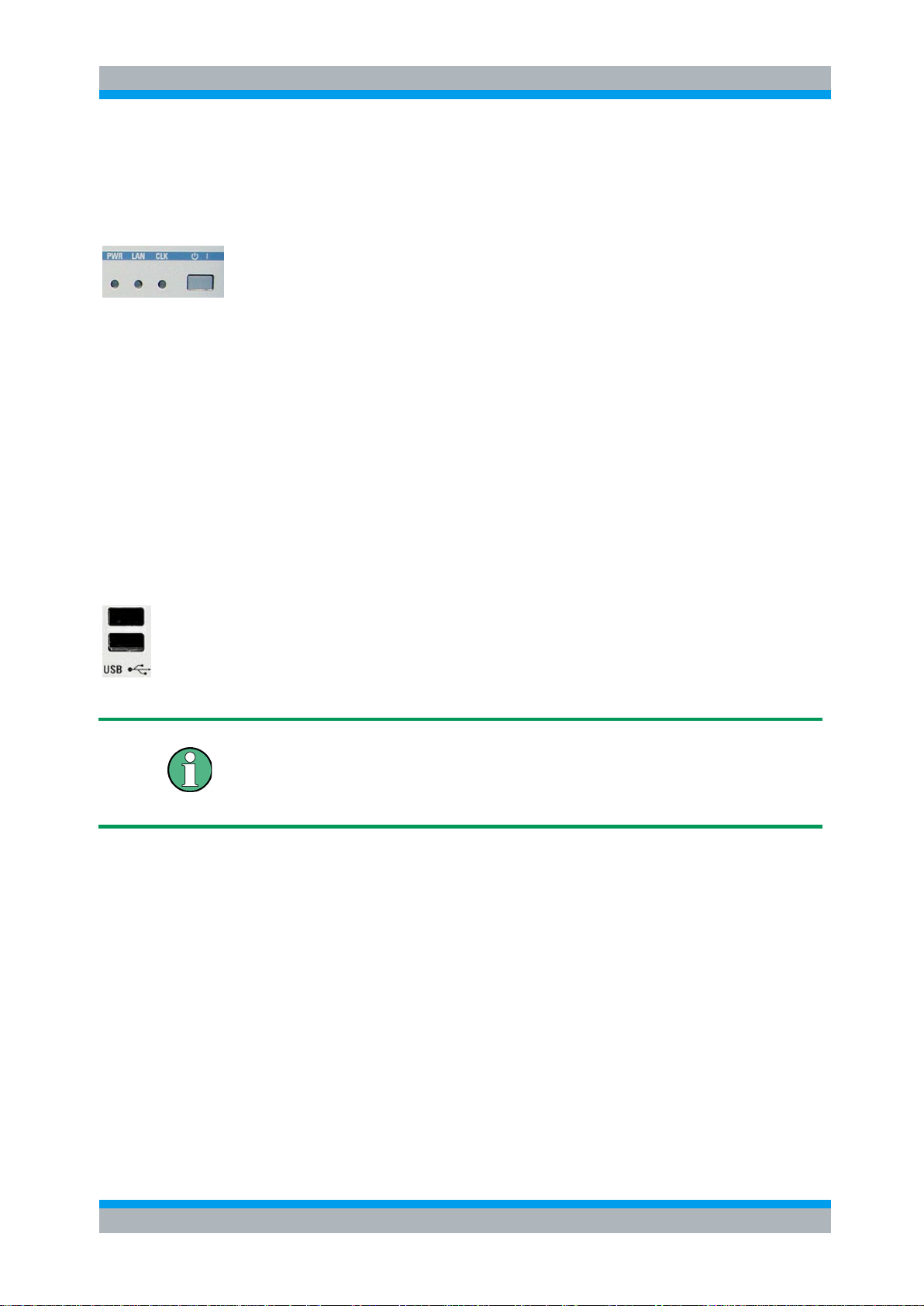
2.1.1 Status LEDs and Standby Key
The status LEDs and the standby toggle switch are located in the bottom right corner
of the front panel. See also chapter 2.5.9.
The status LEDs light to indicate the following instrument states:
PWR: shows standby (yellow LED) and ready state (green LED).
LAN: shows if data are received via LAN network; see Remote Control (chapter 6).
CLK: is flashing if data are transferred via CAN bus.
On an R&S OSP150, the logic is inverted: the CLK indicator goes off shortly during
CAN bus activity.
The STANDBY key serves the following purpose:
Toggle between standby and ready state (indicated by the yellow and green PWR
LED, respectively).
2.1.2 Front Panel Connectors
2.1.2.1 USB Connectors
Single Universal Serial Bus connectors of type A (master USB), used to connect a
keyboard or flash drive. All front panel USB connectors comply with standard USB
2.0; refer to the "Specifications".
USB Connection
The length of passive connecting USB cables should not exceed 1 m. The maximum
current per USB port is 500 mA. It is recommended to use double-shielded USB
cables.

R&S OSP Preparing for Use
Operating Manual 1505.3896.12 - 17 15
2.1.2.2 Monitor Connector
An external monitor with a digital interface can be connected to the MONITOR
DIGITAL connector on the front panel of the R&S OSP120. An external monitor,
together with a keyboard, is a prerequisite for manual intervention in order to define
the LAN configuration or in case of service to have access to the Linux Operating
system.
Monitor connection:
Before the external monitor is connected, the instrument must be switched off
(standby mode) to prevent damage to the monitor and the R&S OSP120. After
connection, the external monitor is detected when the instrument is started. The Linux
Operating system menu of the R&S OSP is then displayed on the external monitor.
Further settings are not required.
It is recommended to use a double-shielded monitor cable equipped with ferrites at
each end.
2.2 Front Panel Tour R&S OSP130
This chapter gives an overview of the front panel controls and connectors of the
R&S OSP130 and gives all information that is necessary to put the instrument into
operation and connect external devices. Notes on reinstallation of the instrument
software appear at the end of the chapter.
The chapter Getting Started of this manual provides an introduction to the operation of
the instrument by means of the control program OSP Panel. For a description of the
operating concept and an overview of the instrument’s capabilities refer to the
Instrument Functions (chapter 5). The graphical user interface on the instrument is
explained in chapter 5.3.
The front panel of the R&S OSP130 has the same STANDBY key and Status LEDs as
the R&S OSP120. See the corresponding sections in chapter 2.1.1 for details. There is
no connector for an external monitor.

R&S OSP Preparing for Use
Operating Manual 1505.3896.12 - 17 16
2.2.1 Navigation Keys
The navigation keys allow access to the various functions of the graphical user
interface. They can be subdivided into three groups.
In the top row next to the screen there are three keys to quickly access different
hierarchy levels in the menus.
pressing the key MENU activates the top level menu.
pressing the key BACK moves up in hierarchy by one menu level.
pressing the key HOME leaves the menu and displays the Main menu screen
In the top row next to the screen there are three keys to quickly access different
hierarchy levels in the menus.
With the cursor keys the focus is moved within the screen elements; see a detailed
description in chapter 5.3.
In the top row next to the screen there are three keys to quickly access different
hierarchy levels in the menus.
pressing the key FUNCTION executes a switching action, if applicable.
pressing the key OK confirms a selection, for example for going to the next menu
level.
pressing the key STATUS displays status information for the chosen item (device or
module) or changes the selection of a switch for path configuration.
2.2.2 Status Keys
The status keys serve the following purposes:
The OFF key is not used at the moment.
The ON key is not used at the moment.
Pressing the RESET key leaves the menu and displays the Main menu screen.
The LOCAL key is not used at the moment.
2.2.3 Status Indicators
The status indicators have the following meaning:
Error in supply voltage, please contact service.
General error condition. Please note any additional information what could have led to
this condition and contact R&S if the error is reproducible.

R&S OSP Preparing for Use
Operating Manual 1505.3896.12 - 17 17
General warning condition. Not used at the moment.
Indicates communication via the CAN interface.
Indicates communication via the CAN interface as well.
2.2.4 Front Panel USB Connectors
Single Universal Serial Bus connectors of type A (master USB), used to connect a
keyboard or flash drive. All front panel USB connectors comply with standard USB
2.0; refer to the "Specifications".
USB Connection
The length of passive connecting USB cables should not exceed 1 m. The maximum
current per USB port is 500 mA. It is recommended to use double-shielded USB
cables.
2.3 Front Panel Tour R&S OSP150
This chapter gives an overview of the front panel controls of the R&S OSP150. The
front panel of the R&S OSP150 is similar to the front panel of the R&S OSP120 having
the Standby key and the three status LEDs but does not have any connector. See
chapter 2.1.1 for the description of the front panel elements.
Please notice that the operation of the CLK LED is different to OSP120 and OSP130.
2.4 Rear Panel Tour
This section gives an overview of the rear panel connectors of the R&S OSP120. The
rear panels of the R&S OSP130 and of the R&S OSP150 are almost identical to it.
The rear connectors and interfaces are described in detail in the complete operating
manual. The following connectors are available on the instruments:

R&S OSP Preparing for Use
Operating Manual 1505.3896.12 - 17 18
LAN connector (RJ-45) is used to integrate the instrument to a Local Area Network,
primarily for remote control purposes. This connector is not available on the
R&S OSP150.
CAN bus connector (D-Sub, 9 pin) is a control port to connect one or several extension
units R&S OSP150.
The R&S OSP owns three slots which can be configured with the options available for
the R&S OSP. The above configuration shows the following options:
Option R&S OSP-B101: Relay module consisting of six coaxial relays of SPDT type;
the RF coaxial connectors are SMA type
Option R&S OSP-B102: Relay module consisting of two coaxial relays of SP6T type;
the RF coaxial connectors are SMA type
Option R&S OSP-B103: I/O module with 16 Bit input / output ports; the connectors are
D-Sub types, 25 pin, female for output and male for input
In case of the options which can be installed in the R&S OSP, the connectors related
to each option are described in detail in chapter 9.2, R&S OSP Module Interfaces.
2.4.1 LAN Connector
8-pin LAN connector RJ-45 used to connect the R&S OSP120 or OSP130 to a Local
Area Network (LAN). Refer to Remote Operation in a LAN.
LAN Connection
Depending on the connection (a non-dedicated network connection or dedicated
connection to a single controller) a standard RJ-45 cable or cross-over RJ-45 cable is
required. See chapter 2.9.1 for further information.
It is recommended to use double-shielded LAN cables of category 6 (SSTP).

R&S OSP Preparing for Use
Operating Manual 1505.3896.12 - 17 19
2.4.2 CAN Bus Connector
9-pin connector D-Sub male used to connect the R&S OSP120 or R&S OSP130 to
extension units R&S OSP150. Refer to Instrument Functions in chapter 5.
Maximum input levels
The maximum input levels and voltages of the input connectors at the front and rear
panel must not be exceeded.
Supply Voltage over CAN bus
In some CAN bus applications the R&S OSP120, OSP130 or OSP150 is required to
deliver the supply voltage to an external device. An example for this is the connection
of the fiber-optic extender R&S OSP-Z104. Using the cable OSP-Z106 is
recommended for this case.
However, when connecting an R&S OSP150 to an OSP120 or OSP130, this supply
voltage line must not be present. Using the connecting cables R&S OSP-Z101 or
R&S OSP-Z102 is recommended. Not observing these precautions may damage the
power supplies in the R&S OSP.
See also chapter 9.1.2.1 for the pinout of the CAN bus connector.
2.4.3 Mains Switch and Connector
The mains connector is located at the bottom left corner of the rear panel.
Next to the connector is a mains fuse, and above the fuse the mains switch. With the
positions “0” the instrument is disconnected from mains, and in position “1” it is
connected. See chapters 2.5.6 and 2.5.7 for more information.

R&S OSP Preparing for Use
Operating Manual 1505.3896.12 - 17 20
2.5 Putting the Instrument into Operation
This section describes the basic steps to be taken when setting up the R&S OSP for
the first time.
Instrument setup
Before turning on the instrument, please make sure that the following conditions are
fulfilled:
Instrument covers are in place and all fasteners are tightened.
Fan openings are unobstructed.
Signal levels at the input connectors are all within the specified ranges.
Signal outputs are correctly connected and not overloaded.
The instrument is dry and shows no condensation.
Non-observance may cause damage to the instrument or other devices in the test
setup.
2.5.1 Unpacking the Instrument and Checking the Shipment
Remove the instrument from its packaging and check the equipment for completeness
using the delivery note and the accessory lists for the various items.
First, pull off the polyethylene protection pads from the instrument's rear feet and then
carefully remove the pads from the instrument handles at the front.
Pull off the corrugated cardboard cover that protects the rear of the instrument.
Carefully unthread the corrugated cardboard cover at the front that protects the
instrument handles and remove it.
Check the instrument for any damage. If there is damage, immediately contact the
carrier who delivered the instrument. In this case, make sure not to discard the box
and packing material.
It is advisable to keep the original packing material in order to prevent control elements
and connectors from being damaged in case the instrument is to be transported or
shipped at a later date.

R&S OSP Preparing for Use
Operating Manual 1505.3896.12 - 17 21
2.5.2 Instrument Setup
The R&S OSP is designed for use under laboratory conditions, either on a bench top
or in a rack. The general ambient conditions required at the operating site are as
follows:
The ambient temperature must be in the ranges specified for operation and for
compliance with specifications (see "Specifications").
All fan openings including the rear panel perforations must be unobstructed. The
distance to the wall should be at least 10 cm.
2.5.3 Bench Top Operation
If the R&S OSP is operated on a bench top, the surface should be flat.
The instrument is used in horizontal position, standing on its feet.
2.5.4 Mounting in a 19" Rack
The instrument can be mounted in 19" racks using a ZZA-211 adapter (order number
1096.3260.00). Please note the mounting instructions supplied with the rack adapter.
Allow for sufficient air supply in the rack.
Make sure that there is sufficient space between the ventilation holes and the rack
casing.
2.5.5 EMI Protective Measures
In order to avoid electromagnetic interference (EMI), the instrument may only be
operated when it is closed and with all shielding covers fitted. Only appropriate
shielded signal and control cables may be used.

R&S OSP Preparing for Use
Operating Manual 1505.3896.12 - 17 22
2.5.6 Connecting the Instrument to the AC Supply
The R&S OSP is automatically adapted to the AC supply voltage supplied. The supply
voltage must be between 100 V and 240 V with frequencies ranging from 50 Hz to
60 Hz (see also the tolerances quoted in the "Specifications"). The mains connector is
located in the lower left corner of the rear panel.
► Connect the instrument to the AC power source using the AC power cable
delivered with the instrument.
The maximum power consumption of the instrument depends on the installed options.
The typical power consumption is also listed in the "Specifications".
The R&S OSP is protected by two fuses located in the fuse holder below the AC power
switch; see Replacing Fuses.
2.5.7 Power on and off
The mains connector is located at the bottom left corner of the rear panel.
To turn the power on or off, press the AC power switch to position I (On) or 0 (Off).
See also Replacing Fuses.
After power-on, the R&S OSP instrument is in ready state after about 30 seconds.
The STANDBY key at the front panel of the instrument is used to toggle between
standby and ready state. The AC power switch can be permanently on.
Switching off is required only if the instrument must be completely removed from the
AC power supply but may be used in order to reduce power consumption when not in
use.
Extension units
If communication between OSP120 or OSP130 and any extension unit OSP150
connected via CAN bus cannot be established properly, try to turn on the extension
unit(s) first before turning on the OSP120 or OSP130.
2.5.8 Replacing Fuses
The instrument is protected by two fuses (IEC 127- T4.0H/250V, stock no.
0020.7600.00) located in the fuse holder below the AC power switch on the rear panel.
Shock hazard
For fuse replacement, ensure that the instrument is switched off and disconnected
from the power supply by removing the plug from the AC power connector.
To replace the fuses

R&S OSP Preparing for Use
Operating Manual 1505.3896.12 - 17 23
1. Open the lid of the AC power connector.
2. Lift the fuse holder out of its slot.
3. Exchange the fuses.
4. Put the fuse holder back in its slot and close the lid.
2.5.9 Standby and Ready State
The STANDBY toggle switch is located in the bottom right corner of the front panel.
After switching on the AC power, the R&S OSP is in ready mode after about
30 seconds.
Press the STANDBY key on the front panel briefly to switch the R&S OSP from the
standby to ready state or vice versa.
In standby state, the left PWR LED is yellow. The standby power only supplies the
power switch circuits. In this state it is safe to switch off the AC power and disconnect
the instrument from the power supply.
After Power On or when changing from Standby to Ready state, the left PWR LED is
immediately switched to green and all modules are power-supplied. Please note that
the Linux operating system of R&S OSP takes about 30 seconds to start up. After this
time the R&S OSP is ready for operation.
Shock hazard
The instrument is still power-supplied while it is in standby mode.
2.6 Maintenance
The R&S OSP does not require any special maintenance. Make sure that the air vents
are not obstructed. The outside of the instrument is suitably cleaned using a soft, nonfluffy dust cloth.
Instrument damage caused by cleaning agents
Cleaning agents contain substances that may damage the instrument, e.g. solvent-
containing cleaning agents may damage the front panel labeling or plastic parts. Never
use cleaning agents such as solvents (thinners, acetone, etc), acids, bases, or other
substances.
For our support center address and a list of useful R&S contact addresses refer to the
pages at the beginning of this manual.

R&S OSP Preparing for Use
Operating Manual 1505.3896.12 - 17 24
2.6.1 Storing and Packing
The R&S OSP can be stored at the temperature range quoted in the data sheet. When
it is stored for a longer period of time the instrument should be protected against dust.
The original packing should be used, particularly the protective caps at the front and
rear, when the instrument is to be transported or dispatched. If the original packing is
no longer available, use a sturdy cardboard box of suitable size and carefully wrap the
instrument to protect it against mechanical damage.
2.7 Connecting External Accessories
The LAN interface at the rear panel of the R&S OSP120 or OSP130 is used for remote
control of the instrument:
● A LAN connection can be established in order to remotely control the instrument
from an external PC (see Connecting a LAN Cable).
In addition the R&S OSP120 provides interfaces for monitor connection and USB
connection:
● An external monitor shows the menus of the Linux Operating System, if any
access or setup within the Linux Operating System should be necessary.
● A keyboard simplifies the entry of data (see Connecting a Keyboard).
● A flash drive supports the firmware update (see Connecting a USB Flash Drive).
2.7.1 Connecting a USB Flash Drive
A USB flash drive can be connected to one of the USB Connectors on the front panel
of the R&S OSP120 or OSP130.
The flash drive is detected automatically when it is connected.
2.7.2 Connecting a Keyboard
A keyboard can be connected to one of the USB Connectors on the front panel of the
R&S OSP120.
The keyboard is detected automatically when it is connected. The default input
language is English – US. Refer to chapter 2.10.1 for changing the keyboard
properties.
Keyboard configuration
The keyboard configuration already is pre-configured.
Operating the R&S OSP120 does not require a keyboard. Usually all essential
functions can be controlled via LAN interface.

R&S OSP Preparing for Use
Operating Manual 1505.3896.12 - 17 25
2.7.3 Connecting a Monitor
A standard monitor can be connected to the DVI-D connector on the front panel of the
R&S OSP120.
Monitor configuration
There is no particular configuration of the monitor required.
Operating the R&S OSP120 does not require a monitor. Usually all essential functions
can be control via LAN interface.
Monitor connection
The monitor must be connected while the instrument is switched off (in standby mode).
Otherwise correct operation can not be guaranteed.
The monitor displays the menus of the Linux Operating System which is integral part of
the R&S OSP120. The monitor together with keyboard is required if any setups /
changes have to be done in the Linux operating system.
2.7.4 Connecting a LAN Cable
A LAN cable can be connected to the LAN connector on the rear panel of the
R&S OSP120 or OSP130. To establish a LAN connection proceed as follows:
Refer to chapter Assigning an IP Address and learn how to avoid connection errors.
Connect an appropriate LAN cable to the LAN port. Use a commercial RJ-45 cable to
establish a non-dedicated network connection, or a cross-over RJ-45 cable to
establish a dedicated connection between the instrument and a single PC.
Dedicated vs. non-dedicated network connections
There are two methods to establish a LAN connection of the R&S OSP:
● A non-dedicated network (Ethernet) connection from the instrument to an existing
network made with an ordinary RJ-45 network cable. The instrument is assigned an
IP address and can coexist with a computer and with other hosts on the same
network.
● A dedicated network connection between the instrument and a single computer
made with a cross-over RJ-45 network cable. The computer must be equipped
with a network adapter and is directly connected to the instrument. The use of
hubs, switches, or gateways is not needed, however, data transfer is still made
using the TCP/IP protocol.

R&S OSP Preparing for Use
Operating Manual 1505.3896.12 - 17 26
2.8 Starting the R&S OSP and Shutting Down
To start the R&S OSP, proceed as follows:
● Make sure that the instrument is connected to the AC power supply and switch
the power switch (see chapter 2.5.7) on the rear panel to position I (On). All
modules of the R&S OSP are powered (the left PWR LED is green) and after
about 30 seconds the instrument is in ready state.
● If necessary, press the STANDBY toggle switch (see chapter 2.5.9) on the front
panel to switch the instrument to ready state (the left PWR LED is green).
● In ready state, the instrument already has booted the Linux Operating System
(see chapter 2.10) and started the R&S OSP application. Independent of the last
setup, the R&S OSP always starts with the default conditions, i.e. all relays in
reset condition.
To shut down the R&S OSP, proceed as follows:
● Press the STANDBY key, which will shut down the Linux operating system and
set the instrument to standby state.
● If desired, set the AC power switch to position 0 (Off).
Standby state
It is recommended to switch the R&S OSP to standby state before disconnecting it
from the AC supply.
2.9 Remote Operation in a LAN
A LAN connection is used to integrate the R&S OSP (not the OSP150) into a
home/company network. The LAN connection is required for:
● Remote control operation of the R&S OSP120 or OSP130.
● Manual control of the R&S OSP from a remote computer using the "OSP Panel"
application.
To establish the connection proceed as follows:
● Assign an IP address to the R&S OSP following the directions below and connect
the instrument to the network as described in chapter 2.7.4, Connecting a LAN
Cable.
2.9.1 Assigning an IP Address
There are two different modes for the OSP LAN configuration. The OSP as it is
delivered works in the LAN configuration as described in chapter 2.9.1.1.
With OSP firmware version 2.51 onwards, the OSP LAN configuration can be setup as
described in chapter 2.9.1.2.

R&S OSP Preparing for Use
Operating Manual 1505.3896.12 - 17 27
The actual LAN configuration can be read out from the OSP by the following SCPI
command:
SYSTem:NETWork:MODe?
2.9.1.1 Default mode of LAN Configuration
The actual LAN configuration is set to mode -> DHCP_AUTO
Depending on the network capacities, the IP address information for the R&S OSP120
or R&S OSP130 can be obtained in different ways.
● If the network supports dynamic TCP/IP configuration using the Dynamic Host
Configuration Protocol (DHCP), all address information can be assigned
automatically.
● If the network does not support DHCP, or if the instrument is set to use alternate
TCP/IP configuration, a static IP address is used.
By default, the R&S OSP is configured either to use:
● A dynamic TCP/IP configuration and obtain all address information automatically.
This means that it is safe to establish a physical connection to the LAN without
any previous R&S OSP configuration.
(Priority 1)
● A user defined static IP address. This address can be defined (but must not) in
addition to the default address. See chapter 3.3.3 for information how to configure
the user defined IP address via the OSP Panel application.
(Priority 2)
● A static default IP address. Per default, the R&S OSP is set to the IP address
192.168.48.147. See also chapter 3.1.
(Priority 3)
Please note the priorities shown above which is related to IP address handling done
by the OSP.
Valid IP addresses
If your network does not support DHCP, or if you choose to disable dynamic TCP/IP
configuration, you must assign valid address information before connecting the
R&S OSP to the LAN. Contact your network administrator to obtain a valid IP address,
because connection errors can affect the entire network.
Reading the IP address
When using the dynamic TCP/IP configuration, the actual IP address information will
be displayed when booting the R&S OSP. Proceed as follows:
Connect the R&S OSP via a commercial RJ-45 cable to your network supporting
DHCP

R&S OSP Preparing for Use
Operating Manual 1505.3896.12 - 17 28
Switch on the R&S OSP120 with Monitor and Keyboard connected (not applicable to
the OSP130)
At the end of the booting process, the IP address will be displayed as shown below for
the OSP120 and the OSP130. The values of the IP address shown are only examples.
Press Okay button or the ENTER key on the keyboard (OK key for the R&S OSP130)
for confirmation and to continue the operation.
Manual TCP/IP configuration
If your network does not support DHCP, proceed as follows:
1. Connect the R&S OSP120 or OSP130 via a cross-over RJ-45 cable to your
computer (or network not supporting DHCP).
2. Set the network configuration of your computer to work with a static IP address.
The following setup is recommended:
3. Switch on the R&S OSP and wait until boot-up is finished.
The R&S OSP now can be accessed under its default IP address from your computer.

R&S OSP Preparing for Use
Operating Manual 1505.3896.12 - 17 29
2.9.1.2 Specific mode of LAN Configuration
The R&S OSP120 can be configured to enable gateway routing.
The actual LAN configuration is set to mode -> DHCP-STATIC
The LAN configuration can be setup using the OSP Panel application. See chapter
3.3.3.
The change over to DHCP-STATIC mode is achieved by the following SCPI command:
SYSTem:NETWork:STATic "<IpAddr>","<Netmask>","<Gateway>".
2.9.2 R&S OSP Panel
The R&S OSP120 has no elements for front panel operating. A “manual” operation is
achieved via the R&S application OSP Panel.
"OSP Panel" is a Windows application which can be used to access and control the
R&S OSP120 or the OSP130 from a remote computer through a LAN connection. The
OSP Panel allows full access to all R&S OSP functions.
To start the OSP Panel connection
4. Connect the R&S OSP to a LAN and determine its IP address; see Remote
Operation in a LAN. It is necessary to have a VISA library installed on your
computer.
5. Install the OSP Panel application on your computer (connected to the LAN). The
VISA libraries which are necessary for running the OSP Panel are available on a
separate disc (NI-VISA I/O Library)..
6. Start the OSP Panel, specify the correct IP address in the OSP Panel, and the
R&S OSP can be manually controlled.
For detailed information about OSP Panel refer to the chapter 3.3 R&S OSP Panel
Functions.
2.10 Linux Operating System
The R&S OSP is equipped with a Linux operating system which has been configured
according to the instrument's features and needs. Changes in the system configuration
can be necessary in order to
● Establish a LAN connection.
● Customize the properties of the keyboard connected to the R&S OSP120.
● Call up additional software tools.

R&S OSP Preparing for Use
Operating Manual 1505.3896.12 - 17 30
Configuration of the operating system, updates
The operating system is adapted to the R&S OSP. To avoid impairment of instrument
functions, only change the settings described in this manual. Existing software must be
modified only with update software released by Rohde & Schwarz. Likewise, only
programs authorized by Rohde & Schwarz for use on the instrument must be
executed.
2.10.1 Keyboard Properties
The keyboard properties can be changed via the console of the Linux Operating
System. To customize the keyboard properties, perform the following steps:
1. Switch off the R&S OSP.
2. R&S OSP120: Connect the external monitor and keyboard to the R&S OSP120
and switch on the instrument. The messages of the Linux boot process are
displayed on the monitor. Wait until the boot process is finished (takes about 30
seconds) and press the <ENTER> key.
3. R&S OSP130: Connect the external keyboard to the R&S OSP120 and switch on
the instrument. Wait until booting is complete. Change from regular display to
Linux system login by pressing the keys CTRL + ALT + F3.
4. When asked for the login, use the login name root and the password root.
To change the keyboard properties to German, type <de> and conform with the
<ENTER> key. The keyboard properties will be kept until the instrument is switched
off. After booting of the instrument, the default keyboard configuration (English US) is
set up again.
2.11 Firmware Update
This chapter contains information on firmware update and Linux operating system
update to the R&S OSP120 or OSP130.
 Loading...