


R&S®NRT2
Power Reflection Meter
User Manual
(;ÜÅÀ2)
1178555002
Version 06

This manual describes the R&S®NRT2 (1430.0509K02) with firmware version FW 01.10 and later.
In addition to the base unit, the following options are described:
●
R&S®NRT2-B8 (1430.0105K02)
© 2022 Rohde & Schwarz GmbH & Co. KG
Muehldorfstr. 15, 81671 Muenchen, Germany
Phone: +49 89 41 29 - 0
Email: info@rohde-schwarz.com
Internet: www.rohde-schwarz.com
Subject to change – data without tolerance limits is not binding.
R&S® is a registered trademark of Rohde & Schwarz GmbH & Co. KG.
Trade names are trademarks of the owners.
1178.5550.02 | Version 06 | R&S®NRT2
Throughout this manual, products from Rohde & Schwarz are indicated without the ® symbol , e.g. R&S®NRT2 is indicated as
R&S NRT2.

R&S®NRT2
Contents
Contents
1 Safety and regulatory information........................................................9
1.1 Safety Instructions........................................................................................................9
1.2 Labels on the product.................................................................................................11
1.3 Warning messages in the documentation................................................................ 12
1.4 Korea Certification Class B........................................................................................12
2 Welcome............................................................................................... 13
2.1 Documentation Overview........................................................................................... 13
2.1.1 Getting Started Manual................................................................................................. 13
2.1.2 User Manual..................................................................................................................13
2.1.3 Instrument Security Procedures....................................................................................13
2.1.4 Printed Safety Instructions............................................................................................ 13
2.1.5 Data Sheets and Brochures.......................................................................................... 13
2.1.6 Release Notes and Open Source Acknowledgment (OSA).......................................... 14
2.2 Key Features................................................................................................................14
3 Getting Started..................................................................................... 15
3.1 Preparing for Use........................................................................................................ 15
3.1.1 Lifting and Carrying....................................................................................................... 15
3.1.2 Unpacking and Checking.............................................................................................. 15
3.1.3 Choosing the Operating Site......................................................................................... 15
3.1.4 Setting Up the Product.................................................................................................. 16
3.1.4.1 Placing the Product on a Bench Top.............................................................................16
3.1.4.2 Mounting the Product in a Rack.................................................................................... 17
3.1.5 Considerations for Test Setup.......................................................................................18
3.1.6 Connecting to Power.....................................................................................................18
3.1.7 Connecting to LAN........................................................................................................ 19
3.1.8 Connecting Power Sensors...........................................................................................19
3.1.8.1 NRT Sensor Connector.................................................................................................19
3.1.8.2 USB 2.0 Host Interfaces................................................................................................20
3.1.9 Connecting USB and External Devices.........................................................................20
3.1.10 Switching On or Off....................................................................................................... 21
3.2 Instrument Tour...........................................................................................................22
3User Manual 1178.5550.02 ─ 06

R&S®NRT2
3.2.1.1 NRT Sensor...................................................................................................................22
3.2.1.2 Touchscreen..................................................................................................................22
3.2.1.3 Keys.............................................................................................................................. 23
3.2.1.4 USB Host Interface....................................................................................................... 24
3.2.1.5 On/Standby Key............................................................................................................ 25
3.2.2.1 Trig In / Out 2 and Out 1 / Trig Out Connectors............................................................ 25
3.2.2.2 Ethernet Interface..........................................................................................................26
3.2.2.3 USB Device Interface....................................................................................................26
3.2.2.4 USB Host Interface....................................................................................................... 26
3.2.2.5 AC Supply and Power Switch....................................................................................... 26
3.2.2.6 IEC 625/IEEE 488 Interface.......................................................................................... 26
Contents
3.2.1 Front Panel Tour............................................................................................................22
3.2.2 Rear Panel Tour............................................................................................................ 25
3.2.2.7 Name Plate................................................................................................................... 27
4 Operating Concepts.............................................................................28
4.1 Manual Operation........................................................................................................28
4.1.1 Main Measurement Dialog............................................................................................ 28
4.1.1.1 Measurement Pane.......................................................................................................29
4.1.2 Status Information......................................................................................................... 30
4.1.3 Notification Center.........................................................................................................31
4.1.4 Editing Parameters........................................................................................................33
4.1.5 Creating and Saving Screenshots.................................................................................33
4.2 Remote Control........................................................................................................... 34
4.2.1 Switching to Remote Control (REMOTE)......................................................................34
4.2.2 Returning to Manual Operation (LOCAL)......................................................................35
5 Measurement and Display Configuration.......................................... 36
5.1 Main Measurement Dialog..........................................................................................36
5.2 Measurement Overview.............................................................................................. 42
5.3 Measurement Main Configuration Dialog................................................................. 43
5.4 Controlling the Measurement.................................................................................... 44
5.5 Triggering.....................................................................................................................45
5.5.1 Trigger States................................................................................................................45
5.5.2 Trigger Sources.............................................................................................................45
4User Manual 1178.5550.02 ─ 06

R&S®NRT2
Contents
5.5.3 Trigger Settings.............................................................................................................46
5.6 Measurement Representation....................................................................................46
6 Sensor Configuration.......................................................................... 50
6.1 Mode Settings..............................................................................................................50
6.2 Correction Settings.....................................................................................................52
6.3 Sensor Frequency.......................................................................................................54
6.4 Filter Settings.............................................................................................................. 55
7 Saving and Recalling Settings............................................................57
8 Zeroing Sensors...................................................................................59
9 System Settings................................................................................... 61
9.1 Connections................................................................................................................ 61
9.1.1 Network Settings........................................................................................................... 62
9.1.2 Remote Settings............................................................................................................65
9.1.3 Input/Output Settings (I/O)............................................................................................ 68
9.1.4 Sensor Manager............................................................................................................70
9.2 Instrument Info............................................................................................................ 73
9.2.1 System Info................................................................................................................... 73
9.2.2 Security Settings........................................................................................................... 76
9.2.3 Option Settings..............................................................................................................79
9.2.4 Open Source Licenses..................................................................................................81
9.3 Hardware Configuration............................................................................................. 81
9.4 Test............................................................................................................................... 82
9.5 Global Settings............................................................................................................83
10 Firmware Update..................................................................................85
10.1 Firmware Update via PC and USB or Ethernet Connection.................................... 85
10.1.1 Hardware and Software Requirements......................................................................... 85
10.1.2 Preparing an Update..................................................................................................... 86
10.1.3 Updating the Application Firmware............................................................................... 87
10.2 Firmware Update via a USB Flash Memory Stick.....................................................90
10.2.1 Hardware and Software Requirements......................................................................... 90
10.2.2 Preparing an Update..................................................................................................... 90
10.2.3 Updating the Application Firmware............................................................................... 91
5User Manual 1178.5550.02 ─ 06

R&S®NRT2
11.2.1 Hierarchy of the Status Registers................................................................................. 93
11.2.2 Structure of a SCPI Status Register..............................................................................94
11.2.3 Status Byte (STB) and Service Request Enable Register (SRE)..................................96
11.2.4 IST Flag and Parallel Poll Enable Register (PPE)........................................................ 97
11.2.5 Questionable Status Register....................................................................................... 97
11.2.6 Standard Event Status and Enable Register (ESR, ESE).............................................98
11.2.7 Operation Status Register.............................................................................................99
Contents
11 Remote Control.................................................................................... 92
11.1 Notation for SCPI Commands....................................................................................92
11.2 Status Reporting System........................................................................................... 93
11.3 Common Commands................................................................................................100
11.4 CALCulate..................................................................................................................109
11.5 CALibration................................................................................................................130
11.6 DIAGnostic.................................................................................................................130
11.7 FORMat...................................................................................................................... 131
11.8 FREQuency................................................................................................................131
11.9 INPut...........................................................................................................................132
11.10 MMEMory................................................................................................................... 133
11.11 OUTPut.......................................................................................................................142
11.12 SENSe........................................................................................................................ 147
11.13 SERVice......................................................................................................................161
11.14 STATus....................................................................................................................... 161
11.15 SYSTem......................................................................................................................165
11.16 TEST...........................................................................................................................183
11.17 TRIGGER....................................................................................................................184
11.18 UNIT............................................................................................................................186
12 Troubleshooting.................................................................................189
12.1 Displaying Information............................................................................................. 189
12.2 Notifications.............................................................................................................. 189
12.2.1 Interpreting Notifications and Their Number............................................................... 189
12.2.1.1 System Notifications....................................................................................................190
12.2.1.2 Power Sensor Notifications......................................................................................... 191
12.2.1.3 License Key Notifications............................................................................................ 191
6User Manual 1178.5550.02 ─ 06

R&S®NRT2
12.2.1.4 Queue Handling Notifications......................................................................................191
Contents
12.3 Performing Tests.......................................................................................................191
12.4 Collecting Information for Technical Support........................................................ 192
12.5 Contacting Customer Support.................................................................................192
13 Transporting.......................................................................................193
14 Maintenance, Storage and Disposal.................................................194
14.1 Cleaning..................................................................................................................... 194
14.2 Storage.......................................................................................................................194
14.3 Disposal..................................................................................................................... 194
Glossary: List of Abbreviations........................................................195
List of commands.............................................................................. 197
Index....................................................................................................203
7User Manual 1178.5550.02 ─ 06

R&S®NRT2
Contents
8User Manual 1178.5550.02 ─ 06

R&S®NRT2
Safety and regulatory information
Safety Instructions
1 Safety and regulatory information
The product documentation helps you use the product safely and efficiently. Follow the
instructions provided here and in the following chapters.
Intended use
Combined with a supported R&S NRT‑Zxx directional power sensor, the R&S NRT2
base unit is intended for power and reflection measurements in development and for
monitoring and maintenance purposes. The supported R&S NRT‑Zxx directional power
sensors are listed in the data sheet. Observe the operating conditions and performance limits stated in the data sheet.
Target audience
The target audience is developers and technicians. The required skills and experience
in power and reflection measurements depend on the used operating concept. While
manual operation is suitable for beginners, remote control requires expertise in power
and reflection measurements.
Main applications are continuous monitoring of transmitter systems and power measurements with digital modulation. A profound knowledge of the intended application
and test setup is recommended.
Where do I find safety information?
Safety information is part of the product documentation. It warns you of potential dangers and gives instructions on how to prevent personal injury or damage caused by
dangerous situations. Safety information is provided as follows:
●
In Chapter 1.1, "Safety Instructions", on page 9. The same information is provided in many languages as printed "Safety Instructions". The printed "Safety
Instructions" are delivered with the product.
●
Throughout the documentation, safety instructions are provided when you need to
take care during setup or operation.
1.1 Safety Instructions
Products from the Rohde & Schwarz group of companies are manufactured according
to the highest technical standards. To use the products safely, follow the instructions
provided here and in the product documentation. Keep the product documentation
nearby and offer it to other users.
Use the product only for its intended use and within its performance limits. Intended
use and limits are described in the product documentation such as the data sheet,
manuals and the printed "Safety Instructions". If you are unsure about the appropriate
use, contact Rohde & Schwarz customer service.
9User Manual 1178.5550.02 ─ 06

R&S®NRT2
Safety and regulatory information
Safety Instructions
Using the product requires specialists or specially trained personnel. These users also
need sound knowledge of at least one of the languages in which the user interfaces
and the product documentation are available.
Never open the casing of the product. Only service personnel authorized by
Rohde & Schwarz are allowed to repair the product. If any part of the product is damaged or broken, stop using the product. Contact Rohde & Schwarz customer service at
http://www.customersupport.rohde-schwarz.com.
Lifting and carrying the product
The maximum weight of the product is provided in the data sheet. To move the product
safely, you can use lifting or transporting equipment such as lift trucks and forklifts. Follow the instructions provided by the equipment manufacturer.
Choosing the operating site
Only use the product indoors. The product casing is not waterproof. Water that enters
can electrically connect the casing with live parts, which can lead to electric shock,
serious personal injury or death if you touch the casing. If Rohde & Schwarz provides
accessories designed for your product, e.g. a carrying bag, you can use the product
outdoors.
Unless otherwise specified, you can operate the product up to an altitude of 2000 m
above sea level. The product is suitable for pollution degree 2 environments where
nonconductive contamination can occur. For more information on environmental conditions such as ambient temperature and humidity, see the data sheet.
Setting up the product
Always place the product on a stable, flat and level surface with the bottom of the product facing down. If the product is designed for different positions, secure the product so
that it cannot fall over.
If the product has foldable feet, always fold the feet completely in or out to ensure stability. The feet can collapse if they are not folded out completely or if the product is
moved without lifting it. The foldable feet are designed to carry the weight of the product, but not an extra load.
If stacking is possible, keep in mind that a stack of products can fall over and cause
injury.
If you mount products in a rack, ensure that the rack has sufficient load capacity and
stability. Observe the specifications of the rack manufacturer. Always install the products from the bottom shelf to the top shelf so that the rack stands securely. Secure the
product so that it cannot fall off the rack.
Connecting to power
The product is an overvoltage category II product. Connect the product to a fixed
installation used to supply energy-consuming equipment such as household appliances and similar loads. Keep in mind that electrically powered products have risks, such
as electric shock, fire, personal injury or even death.
10User Manual 1178.5550.02 ─ 06
R&S®NRT2
Safety and regulatory information
Labels on the product
Take the following measures for your safety:
●
Before switching on the product, ensure that the voltage and frequency indicated
on the product match the available power source. If the power adapter does not
adjust automatically, set the correct value and check the rating of the fuse.
●
Only use the power cable delivered with the product. It complies with country-specific safety requirements. Only insert the plug into an outlet with protective conductor terminal.
●
Only use intact cables and route them carefully so that they cannot be damaged.
Check the power cables regularly to ensure that they are undamaged. Also ensure
that nobody can trip over loose cables.
●
If the product needs an external power supply, use the power supply that is delivered with the product or that is recommended in the product documentation or a
power supply that conforms to the country-specific regulations.
●
Only connect the product to a power source with a fuse protection of maximum
20 A.
●
Ensure that you can disconnect the product from the power source at any time.
Pull the power plug to disconnect the product. The power plug must be easily
accessible. If the product is integrated into a system that does not meet these
requirements, provide an easily accessible circuit breaker at the system level.
Cleaning the product
Use a dry, lint-free cloth to clean the product. When cleaning, keep in mind that the
casing is not waterproof. Do not use liquid cleaning agents.
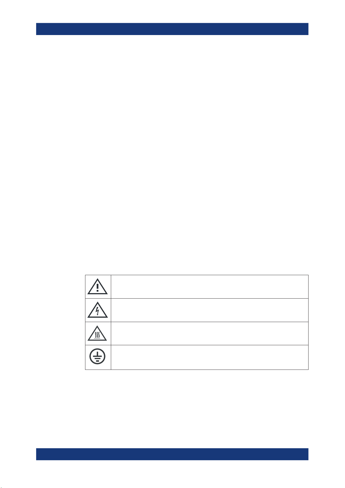
Meaning of safety labels
Safety labels on the product warn against potential hazards.
Potential hazard
Read the product documentation to avoid personal injury or product damage.
Electrical hazard
Indicates live parts. Risk of electric shock, fire, personal injury or even death.
Hot surface
Do not touch. Risk of skin burns. Risk of fire.
Protective conductor terminal
Connect this terminal to a grounded external conductor or to protective ground. This connec-
tion protects you against electric shock if an electric problem occurs.
1.2 Labels on the product
Labels on the casing inform about:
●
Personal safety, see "Meaning of safety labels" on page 11
11User Manual 1178.5550.02 ─ 06

R&S®NRT2
Safety and regulatory information
Korea Certification Class B
●
Environment safety, see Table 1-1
●
Identification of the product, see Chapter 3.2.2.7, "Name Plate", on page 27.
Table 1-1: Labels regarding environment safety
Labeling in line with EN 50419 for disposal of electrical and electronic equipment after the product has come to the end of its service life.
For more information, see "Disposing electrical and electronic equipment" on page 194.
1.3 Warning messages in the documentation
A warning message points out a risk or danger that you need to be aware of. The signal word indicates the severity of the safety hazard and how likely it will occur if you do
not follow the safety precautions.
WARNING
Potentially hazardous situation. Could result in death or serious injury if not avoided.
CAUTION
Potentially hazardous situation. Could result in minor or moderate injury if not avoided.
NOTICE
Potential risks of damage. Could result in damage to the supported product or to other
property.
1.4 Korea Certification Class B
이 기기는 가정용(B급) 전자파 적합기기로서 주로 가정에서 사용하는 것을 목적으로 하
며, 모든 지역에서 사용할 수 있습니다.
12User Manual 1178.5550.02 ─ 06

R&S®NRT2
2.1.1 Getting Started Manual
Welcome
Documentation Overview
2 Welcome
This chapter provides an overview of the user documentation and an introduction to
the R&S NRT2.
2.1 Documentation Overview
This section provides an overview of the R&S NRT2 user documentation. Unless
specified otherwise, you find the documents on the R&S NRT2 product page at:
www.rohde-schwarz.com/manual/NRT2
Introduces the R&S NRT2 and describes how to set up and start working with the product. A printed version is delivered with the instrument.
2.1.2 User Manual
Contains the description of all instrument modes and functions. It also provides an
introduction to remote control, a complete description of the remote control commands
with programming examples, and information on maintenance, instrument interfaces
and error messages. Includes the contents of the getting started manual .
2.1.3 Instrument Security Procedures
Deals with security issues when working with the R&S NRT2 in secure areas. It is
available for download on the Internet.
2.1.4 Printed Safety Instructions
Provides safety information in many languages. The printed document is delivered with
the product.
2.1.5 Data Sheets and Brochures
The data sheet contains the technical specifications of the R&S NRT2. It also lists the
firmware applications and their order numbers, and optional accessories.
The brochure provides an overview of the instrument and deals with the specific characteristics.
See www.rohde-schwarz.com/brochure-datasheet/NRT2
13User Manual 1178.5550.02 ─ 06

R&S®NRT2
2.1.6 Release Notes and Open Source Acknowledgment (OSA)
Welcome
Key Features
The release notes list new features, improvements and known issues of the current
firmware version.
The open source acknowledgment and the license texts of open source software packages used in the R&S NRT2 software are provided under:
[System] > "Instrument Info" > "Open Source Options"
For further details, see Chapter 9.2.4, "Open Source Licenses", on page 81.
See www.rohde-schwarz.com/firmware/NRT2
2.2 Key Features
Directional power measurements, measuring forward and reverse power under operating conditions, are required when installing, servicing and monitoring transmitters,
antennas and RF generators. The compact R&S NRT2 power reflection meter supports all the measurement functions of the R&S NRT‑Zxx directional power sensors.
Thanks to the wide range of measurement functions and high accuracy, you can use
them in research, development and production.
The large, user-friendly touchscreen simultaneously displays the forward and reverse
power. The base unit is exceptionally easy and intuitive to use and can be remotely
controlled via LAN, GPIB (GPIB/IEEE488 Interface (R&S NRT2-B8)) or USB.
Key facts:
●
Simultaneous display of forward and reverse power
●
Measurement of average power, average burst power, peak power, crest factor,
CCDF and mismatch
●
5" color touchscreen
●
Direct operation of the R&S NRT‑Zxx directional power sensors from a PC
●
Frequency-range from 25 MHz to 4 GHz (sensor-dependent)
14User Manual 1178.5550.02 ─ 06

R&S®NRT2
Getting Started
Preparing for Use
3 Getting Started
3.1 Preparing for Use
Here, you can find basic information about setting up the product for the first time.
● Lifting and Carrying.................................................................................................15
● Unpacking and Checking........................................................................................ 15
● Choosing the Operating Site...................................................................................15
● Setting Up the Product............................................................................................16
● Considerations for Test Setup.................................................................................18
● Connecting to Power...............................................................................................18
● Connecting to LAN..................................................................................................19
● Connecting Power Sensors.....................................................................................19
● Connecting USB and External Devices...................................................................20
● Switching On or Off.................................................................................................21
3.1.1 Lifting and Carrying
See "Lifting and carrying the product" on page 10.
The R&S NRT2 weighs below 3 kg, details are provided in the data sheet. Due to the
low weight, you can move the R&S NRT2 easily.
3.1.2 Unpacking and Checking
1. Unpack the product carefully.
2. Retain the original packing material. Use it when transporting or shipping the product later.
3. Using the delivery notes, check the equipment for completeness.
4. Check the equipment for damage.
If the delivery is incomplete or equipment is damaged, contact Rohde & Schwarz.
3.1.3 Choosing the Operating Site
Specific operating conditions ensure proper operation and avoid damage to the product and connected devices. For information on environmental conditions such as ambient temperature and humidity, see the data sheet.
See also "Choosing the operating site" on page 10.
15User Manual 1178.5550.02 ─ 06

R&S®NRT2
3.1.4 Setting Up the Product
Getting Started
Preparing for Use
Electromagnetic compatibility classes
The electromagnetic compatibility (EMC) class indicates where you can operate the
product. The EMC class of the product is given in the data sheet under "General data".
●
Class B equipment is suitable for use in:
– Residential environments
– Environments that are directly connected to a low-voltage supply network that
supplies residential buildings
●
Class A equipment is intended for use in industrial environments. It can cause
radio disturbances in residential environments due to possible conducted and radiated disturbances. It is therefore not suitable for class B environments.
If class A equipment causes radio disturbances, take appropriate measures to
eliminate them.
See also:
●
"Setting up the product" on page 10
●
"Intended use" on page 9
3.1.4.1 Placing the Product on a Bench Top
The R&S NRT2 is a small and lightweight product. You can stack the R&S NRT2 with
other products, but place the R&S NRT2 on top. In the following procedure, the weight
indication for stacking refers to the most common design of larger Rohde & Schwarz
instruments. Verify the load suitable for your product before stacking.
To place the product on a bench top
1. Place the product on a stable, flat and level surface. Ensure that the surface can
support the weight of the product. For information on the weight, see the data
sheet.
CAUTION! Foldable feet can collapse. See "Setting up the product" on page 10.
2.
Always fold the feet completely in or out. With folded-out feet, do not place any-
thing on top or underneath the product.
WARNING! A stack of products can fall over and cause injury. Never stack more
3.
than three products on top of each other. Instead, mount them in a rack.
Stack as follows:
● If the products have foldable feet, fold them in completely.
● It is best if all products have the same dimensions (width and length). If the
products have different dimensions, stack according to size and place the
smallest product on top.
● Do not exceed the permissible total load placed on the product at the bottom of
the stack:
– 50 kg when stacking products of identical dimensions (left figure).
16User Manual 1178.5550.02 ─ 06

R&S®NRT2
– 25 kg when stacking smaller products on top (middle figure).
Left = Stacked correctly, same dimensions
Middle = Stacked correctly, different dimensions
Right = Stacked incorrectly, too many products
NOTICE! Overheating can damage the product.
4.
Prevent overheating as follows:
Getting Started
Preparing for Use
● Keep a minimum distance of 10 cm between the fan openings of the product
and any object in the vicinity.
● Do not place the product next to heat-generating equipment such as radiators
or other products.
3.1.4.2 Mounting the Product in a Rack
To prepare the rack
1. Observe the requirements and instructions in "Setting up the product" on page 10.
NOTICE! Insufficient airflow can cause overheating and damage the product.
2.
Design and implement an efficient ventilation concept for the rack.
To mount the product in a rack
1. Use an adapter kit to prepare the product for rack mounting.
a) Order the rack adapter kit designed for the product. For the order number, see
data sheet.
b) Mount the adapter kit. Follow the assembly instructions provided with the
adapter kit.
2. Grab the product by the handles and push it onto the shelf until the rack brackets fit
closely to the rack.
3. Tighten all screws on the rack brackets to secure the product in the rack.
To unmount the product from a rack
1. Loosen the screws at the rack brackets.
17User Manual 1178.5550.02 ─ 06

R&S®NRT2
3.1.5 Considerations for Test Setup
Getting Started
Preparing for Use
2. Remove the product from the rack.
3. If placing the product on a bench top again, unmount the adapter kit from the product. Follow the instructions provided with the adapter kit.
Cable selection and electromagnetic interference (EMI)
Electromagnetic interference (EMI) can affect the measurement results.
To suppress electromagnetic radiation during operation:
●
Use high-quality shielded cables, for example, double-shielded RF and LAN
cables.
●
Always terminate open cable ends.
●
Ensure that connected external devices comply with EMC regulations.
●
Do not use USB connecting cables exceeding 5 m.
Preventing electrostatic discharge (ESD)
Electrostatic discharge is most likely to occur when you connect or disconnect a DUT.
NOTICE! Risk of electrostatic discharge. Electrostatic discharge can damage the
►
electronic components of the product and the device under test (DUT).
Ground yourself to prevent electrostatic discharge damage:
a) Use a wrist strap and cord to connect yourself to ground.
b) Use a conductive floor mat and heel strap combination.
3.1.6 Connecting to Power
The R&S NRT2 can be used with different AC power voltages and adapts itself automatically to them. Adjusting the R&S NRT2 to a particular AC supply voltage is therefore not required. Refer to the data sheet for the requirements of voltage and frequency.
For safety information, see "Connecting to power" on page 10.
1. Plug the AC power cable into the AC power connector on the rear panel of the
product. Only use the AC power cable delivered with the product.
2. Plug the AC power cable into a power outlet with ground contact.
The required ratings are listed next to the AC power connector and in the data
sheet.
Further information:
●
Chapter 3.2.2.5, "AC Supply and Power Switch", on page 26
18User Manual 1178.5550.02 ─ 06
R&S®NRT2
3.1.7 Connecting to LAN
3.1.8 Connecting Power Sensors
3.1.8.1 NRT Sensor Connector
Getting Started
Preparing for Use
See Chapter 9.1.1, "Network Settings", on page 62.
The R&S NRT2 supports the R&S NRT‑Zxx directional power sensors listed in the data
sheet. You have two choices for connecting the power sensors, but only one measurement at a time is possible.
See Figure 3-2.
Communication between the R&S NRT‑Zxx directional power sensor and a base unit is
only possible with a baud rate setting of 38400 Bd. This setting is the factory default
that must be restored if the setting was changed. If the R&S NRT‑Zxx directional power
sensor is not recognized by the base unit, check that the baud rate setting of the
R&S NRT‑Zxx directional power sensor is 38400 Bd.
See the manual of the R&S NRT‑Zxx directional power sensor for details.
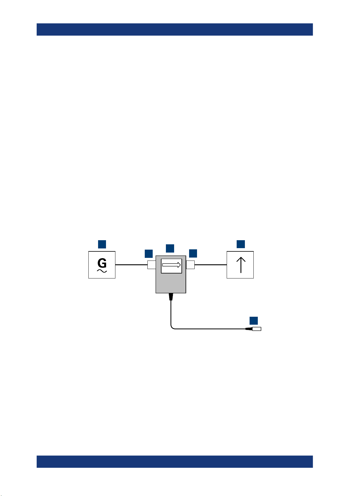
The arrow on the power sensor casing shows the forward power flow.
1
2
3
4
5
6
Figure 3-1: Connecting to source and load
1 = source
2 = port 1 (RF connector)
3 = R&S NRT‑Zxx directional power sensor
4 = port 2 (RF connector)
5 = load
6 = host interface connector
To connect the R&S NRT‑Zxx directional power sensor
Connect the R&S NRT‑Zxx directional power sensor between source and load of your
test setup as follows.
19User Manual 1178.5550.02 ─ 06

R&S®NRT2
Getting Started
Preparing for Use
CAUTION! Risk of electric shock and severe skin burns. During the measurement,
1.
the RF power flow can be high. Connect both RF connectors tightly to avoid power
leakage.
Connect RF connector (2, port 1) to the source.
a) Insert RF connector (2) straight into the RF connector of the source. Take care
not to tilt the R&S NRT‑Zxx directional power sensor.
b) Tighten the RF connector securely by hand.
2. Connect RF connector (4, port 2) to the load.
a) Insert RF connector (4) straight into the RF connector of the load. Take care
not to tilt the R&S NRT‑Zxx directional power sensor.
b) Tighten the RF connector securely by hand.
3. Connect the host interface connector of the R&S NRT‑Zxx directional power sensor
(6) to the NRT sensor connector.
To disconnect the R&S NRT‑Zxx directional power sensor
CAUTION! Risk of electric shock and severe skin burns. During the measurement,
1.
the RF power flow can be high.
Switch off the RF power before touching the RF connectors.
2. Unscrew the RF connectors by hand.
3. Disconnect the cable of the R&S NRT‑Zxx directional power sensor (6) from the
NRT sensor connector.
3.1.8.2 USB 2.0 Host Interfaces
See Figure 3-2 and Chapter 3.2.2.4, "USB Host Interface", on page 26.
1. Connect the R&S NRT‑Z5 USB interface adapter to the R&S NRT‑Zxx power sensor.
2. Connect the USB connector of the adapter to the R&S NRT2.
3. Connect the R&S NRT‑Zxx power sensor between source and load. See Chap-
ter 3.1.8.1, "NRT Sensor Connector", on page 19.
3.1.9 Connecting USB and External Devices
Apart from connecting power sensors, you can use the USB interfaces to connect USB
devices. You can increase the number of connected devices by using USB hubs.
Due to the large number of available USB devices, there is almost no limit to the possible expansions. In the following, useful USB devices are listed exemplarily:
●
Memory stick for easy transfer of data to/from a computer (e.g. firmware updates).
●
Mouse if you prefer this way of operation over a touchscreen.
20User Manual 1178.5550.02 ─ 06

R&S®NRT2
3.1.10 Switching On or Off
Getting Started
Preparing for Use
Table 3-1: Overview of power states
Status LED Position of power switch
Off Off [0]
Standby
Ready
orange
green
[I]
[I]
To switch on the product
The product is off but connected to power.
1. Set the switch on the power supply to position [I]. See Chapter 3.2.2.5, "AC Supply
and Power Switch", on page 26.
The LED of the [standby] key is orange. See Chapter 3.2.1.5, "On/Standby Key",
on page 25.
2. Press the [standby] key.
The LED changes to green. The product boots.
See Chapter 4.1.1, "Main Measurement Dialog", on page 28.
If the previous session ended regularly, the product uses the settings from the last
session.
3. If you want to return to a defined initial state, perform a preset.
See "Preset" on page 58.
To shut down the product
The product is in the ready state.
► Press the [standby] key.
The operating system shuts down. The LED changes to orange.
To disconnect from power
The product is in the standby state.
NOTICE! Risk of data loss. If you disconnect the product from power when it is in
1.
the ready state, you can lose settings and data. Shut it down first.
Set the switch on the power supply to position [0].
The LED of the standby key is switched off.
2. Disconnect the product from the power source.
Further information:
●
Chapter 7, "Saving and Recalling Settings", on page 57
●
Chapter 3.2.1.5, "On/Standby Key", on page 25
21User Manual 1178.5550.02 ─ 06
R&S®NRT2
3.2.1 Front Panel Tour
Getting Started
Instrument Tour
3.2 Instrument Tour
The meanings of the labels on the product are described in Chapter 1.2, "Labels on the
product", on page 11.
● Front Panel Tour......................................................................................................22
● Rear Panel Tour......................................................................................................25
7
6
5
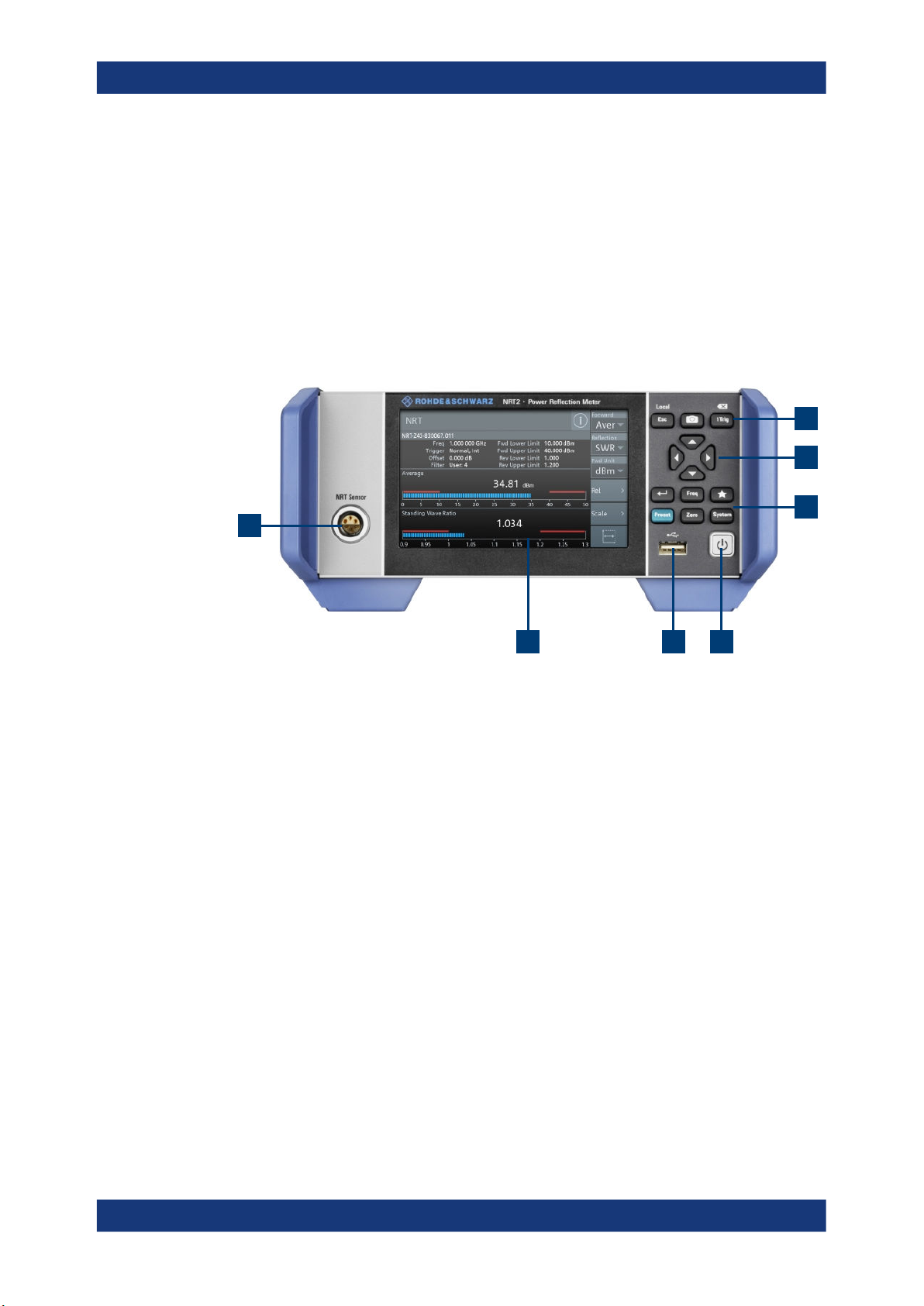
1
Figure 3-2: Front panel of the R&S NRT2
1 = NRT sensor connector, see Chapter 3.2.1.1, "NRT Sensor", on page 22.
2 = Touchscreen, see Chapter 3.2.1.2, "Touchscreen", on page 22.
3 = USB host interface, see Chapter 3.2.1.4, "USB Host Interface", on page 24.
4 = On/standby key, see Chapter 3.2.1.5, "On/Standby Key", on page 25.
5, 7 = Keys, see Chapter 3.2.1.3, "Keys", on page 23.
6 = Cursor keys, see "Cursor keys" on page 24.
3.2.1.1 NRT Sensor
See (1) in Figure 3-2.
To the left of the display, the R&S NRT2 provides the sensor interface. For supported
power sensors, see the product brochure.
Further information:
●
Chapter 3.1.8, "Connecting Power Sensors", on page 19
3.2.1.2 Touchscreen
2 3 4
See (2) in Figure 3-2.
22User Manual 1178.5550.02 ─ 06

R&S®NRT2
3.2.1.3 Keys
Getting Started
Instrument Tour
The R&S NRT2 displays results in panes. Depending on the measurement mode, values are displayed digitally or graphically.
False triggers can occur
If an object (e.g. a human finger) that is charged with static electricity is brought near
the touch panel, false triggers can occur.
This behavior is caused by the principle of operation of a PCAP (projected capacitive)
touch panel.
Further information:
●
"Using the touchscreen" on page 28
See (3) in Figure 3-2.
[Esc] / Local
If you press shortly:
●
Changes to the next-higher hierarchy level.
●
Escapes from the entry mode in text boxes and lists.
●
Closes dialogs without losing any entries that have been made.
●
Switches from remote control mode (all controls disabled) to manual operation.
If you press and hold:
●
Goes to the main measurement dialog.
See Chapter 4.1.1, "Main Measurement Dialog", on page 28.
Further information:
●
"Going back to a higher hierarchy level" on page 28
●
Chapter 4.2.2, "Returning to Manual Operation (LOCAL)", on page 35
Screenshot
Creates a screenshot of the current display.
See Chapter 4.1.5, "Creating and Saving Screenshots", on page 33.
Remote command:
SYSTem:HCOPy on page 175
[1Trig] / Delete
●
Controls the measurements depending on the trigger mode:
– For all trigger modes except "Single", starts and stops the measurement.
– For the "Single" trigger mode, enables and triggers the measurement.
Changes of the trigger state apply to all measurements.
See also "Trigger Mode" on page 46.
●
Deletes numbers or text in a field so that you can enter a new value.
Enter
●
Confirms entries in text fields, dialogs and selections in lists.
●
Shows a frame around the control in focus. You can change the focus using the
Cursor keys.
23User Manual 1178.5550.02 ─ 06

R&S®NRT2
Getting Started
Instrument Tour
[Freq]
Sets the carrier frequency of the applied signal. This value is used for frequencyresponse correction of the measurement result.
Remote command:
[SENSe<Sensor>:]FREQuency[:CW] on page 151
Favorites
Reserved for future use.
[Preset]
Opens the "Save / Recall / Preset" dialog.
See Chapter 7, "Saving and Recalling Settings", on page 57.
If you press [Preset] again, the preset function starts.
See "Preset" on page 58.
If you press the [Preset] key during booting, the R&S NRT2 starts with the factory
default state.
[Zero]
Pressing [Zero] opens the "Zeroing Sensors" dialog.
If you press [Zero] again, zeroing starts.
Also displays status information:
●
Zeroing status
●
Sensor status
[System]
Opens the "System Overview" dialog.
See Chapter 9, "System Settings", on page 61.
Cursor keys
See (4) in Figure 3-2.
The cursor keys are context-sensitive. The control in focus is indicated by a focus
frame. Use the cursor keys as follows:
●
Selecting an element in the navigation pane.
●
Selecting the active pane.
●
Selecting an element from a list.
●
Moving the cursor in text boxes.
●
Changing the value of an entry in a text box.
3.2.1.4 USB Host Interface
See (5) in Figure 3-2.
USB 2.0 (universal serial bus) interface of the type A (host USB). Used to connect:
●
R&S NRT‑Zxx power sensor using the R&S NRT‑Z5 USB interface adapter
●
External devices like a keyboard, mouse, or memory stick
24User Manual 1178.5550.02 ─ 06
R&S®NRT2
3.2.1.5 On/Standby Key
3.2.2 Rear Panel Tour
Getting Started
Instrument Tour
Further information:
●
Chapter 3.1.8.2, "USB 2.0 Host Interfaces", on page 20
●
Chapter 3.1.9, "Connecting USB and External Devices", on page 20
See (6) in Figure 3-2.
The on/standby key switches between standby and ready state, if the power switch is
set to [I].
Further information:
●
Chapter 3.2.2.5, "AC Supply and Power Switch", on page 26
●
Chapter 3.1.10, "Switching On or Off", on page 21
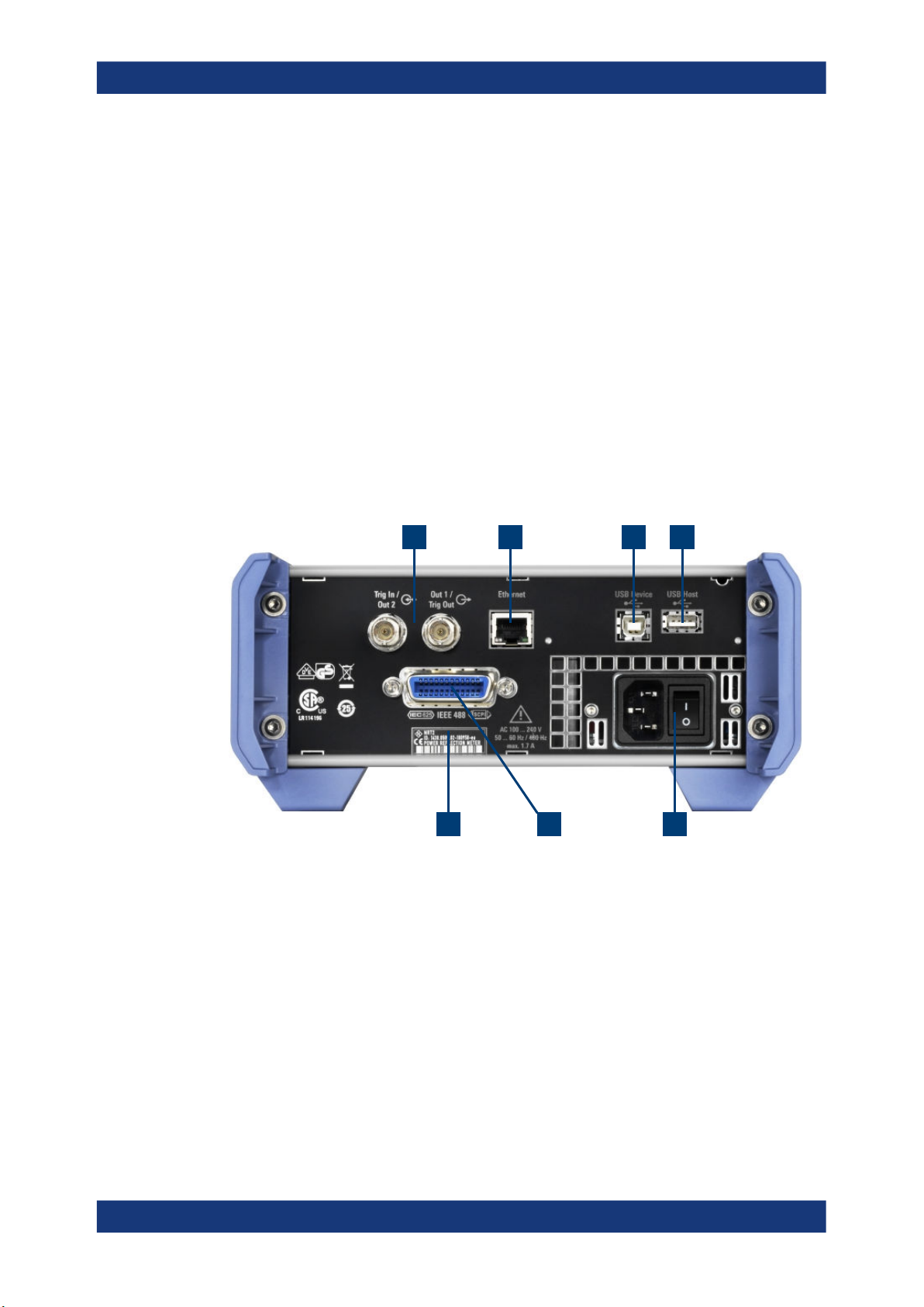
1 2 3 4
567
Figure 3-3: Rear panel of the R&S NRT2
1 = Trig In / Out 2 and Out 1 / Trig Out connectors, see Chapter 3.2.2.1, "Trig In / Out 2 and Out 1 / Trig Out
Connectors", on page 25.
2 = Ethernet interface, see Chapter 3.2.2.2, "Ethernet Interface", on page 26.
3 = USB device interface, see Chapter 3.2.2.3, "USB Device Interface", on page 26.
4 = USB host interface, see Chapter 3.2.2.4, "USB Host Interface", on page 26.
5 = AC supply and power switch, see Chapter 3.2.2.5, "AC Supply and Power Switch", on page 26.
6 = IEC 625/IEEE 488 interface, see Chapter 3.2.2.6, "IEC 625/IEEE 488 Interface", on page 26.
7 = Name plate, see Chapter 3.2.2.7, "Name Plate", on page 27
3.2.2.1 Trig In / Out 2 and Out 1 / Trig Out Connectors
See (1) in Figure 3-3.
25User Manual 1178.5550.02 ─ 06

R&S®NRT2
3.2.2.2 Ethernet Interface
3.2.2.3 USB Device Interface
Getting Started
Instrument Tour
The Out 1 / Trig Out BNC connectors supply an analog signal with a voltage between
0 V and 2.5 V. It can be used to output a voltage that is proportional to the measured
value (e.g. for level regulation) or a digital signal for limit monitoring.
The Trig In / Out 2 BNC connectors can be used either as an external trigger input with
a switchable impedance (10 kΩ or 50 Ω) or as a second analog output.
By default, both connectors are disabled.
Further information:
●
"I/O 1, I/O 2 tabs" on page 68
See (2) in Figure 3-3.
The Ethernet connector is an RJ45 socket for remote controlling the R&S NRT2 via a
network.
See (3) in Figure 3-3.
USB 2.0 (universal serial bus) interface of the type B (receptacle). Used to connect the
R&S NRT2 to a computer for USB remote control.
3.2.2.4 USB Host Interface
See (4) in Figure 3-3.
See Chapter 3.2.1.4, "USB Host Interface", on page 24.
3.2.2.5 AC Supply and Power Switch
See (5) in Figure 3-3.
Observe the safety instructions in "Connecting to power" on page 10.
When the R&S NRT2 is connected to the AC supply, it automatically sets itself to the
correct range for the applied voltage. The range is printed on the casing. There is no
need to set the voltage manually.
Further information:
●
Chapter 3.1.6, "Connecting to Power", on page 18
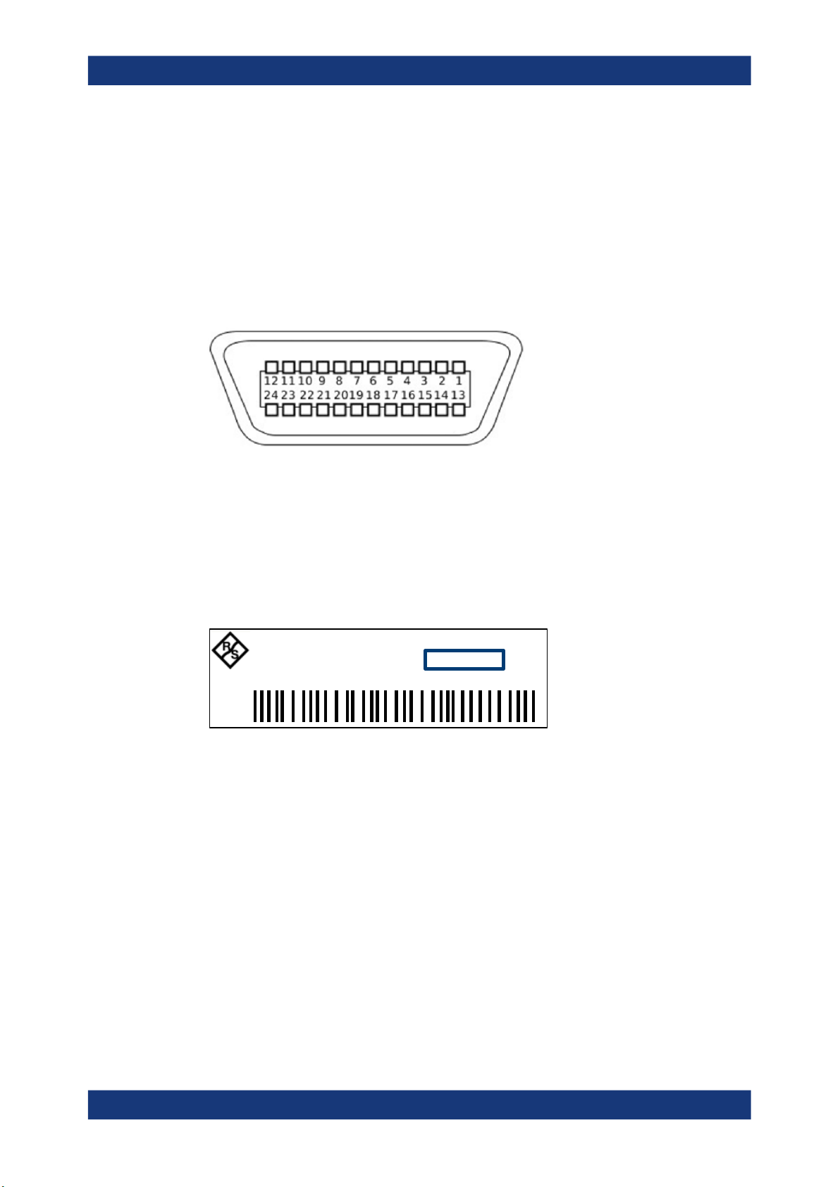
3.2.2.6 IEC 625/IEEE 488 Interface
See (6) in Figure 3-3.
Requires GPIB/IEEE488 Interface (R&S NRT2-B8).
26User Manual 1178.5550.02 ─ 06
R&S®NRT2
Getting Started
Instrument Tour
IEC bus (IEEE 488) interface for remote control of the R&S NRT2. Used to connect a
controller to remote control the R&S NRT2. Use a shielded cable for the connection.
Characteristics of the IEC bus (IEEE 488) interface:
●
8-bit parallel data transfer
●
Bidirectional data transfer
●
Three-wire handshake
●
High data transfer rate
●
Maximum length of connecting cables 15 m (single connection 2 m)
3.2.2.7
Name Plate
See (7) in Figure 3-3.
Shows the type, identification and name of the R&S NRT2. The device ID consists of:
<stock number> - <serial number> - <checksum>
The framed 6 digits in Figure 3-4 are the individual serial number.
NRT2
ID: 1430.0509K02 - 100958 - eu
POWER REFLECTION METER
Figure 3-4: Name plate
The name plate also shows the parts of the default hostname. The default hostname
consists of <type>-<serial number>.
For the R&S NRT2 with the name plate shown in Figure 3-4, the default hostname is:
NRT2-100958
Further information:
●
"System Info" on page 74
●
"Host Name" on page 63
27User Manual 1178.5550.02 ─ 06

R&S®NRT2
Operating Concepts
Manual Operation
4 Operating Concepts
● Manual Operation....................................................................................................28
● Remote Control.......................................................................................................34
4.1 Manual Operation
Using the graphical user interface of the R&S NRT2 and the keys on the front panel,
you can easily configure the settings and measure in the provided measurement
modes.
Using the touchscreen
A touchscreen allows you to interact with the software using various finger gestures on
the screen. The basic gestures supported by the software and most applications are
described here. Further actions using the same gestures may be possible.
Tap = touch the screen quickly, usually on a specific element. You can tap most ele-
ments on the screen to access the settings belonging to that element (topic).
In graphs, use the following gestures:
●
Pan = put your fingers on the touchscreen and move them while keeping contact.
Thus, you can bring offscreen extensions of the graph into view.
●
Pinch = move two fingers toward each other to change the zoom.
Going back to a higher hierarchy level
The [Esc] key is the essential control element to navigate back, for example after you
have opened a dialog by tapping an element.
►
Press
►
Keep pressed to go to the highest hierarchy level, the main measurement dialog.
shortly to change to the next-higher hierarchy level.
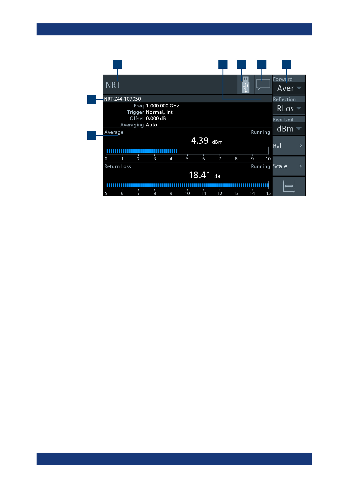
4.1.1 Main Measurement Dialog
1. Connect a power sensor to the R&S NRT2.
See Chapter 3.1.8, "Connecting Power Sensors", on page 19.
2. Boot the R&S NRT2.
After successful booting, the R&S NRT2 displays the main measurement dialog.
28User Manual 1178.5550.02 ─ 06
R&S®NRT2
Operating Concepts
Manual Operation
3 4 5 6 7
2
1
Figure 4-1: Start dialog
1 = Measurement pane, see Chapter 4.1.1.1, "Measurement Pane", on page 29.
2 = Connected sensor
3 = Title
4 = Measurement type
5 = Notification center status, see Chapter 4.1.3, "Notification Center", on page 31.
6 = Status information. See Chapter 4.1.2, "Status Information", on page 30.
7 = Navigation pane
The navigation pane gives quick access to important settings.
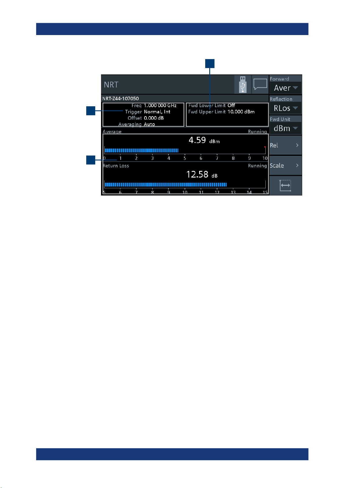
4.1.1.1 Measurement Pane
In the measurement pane, the settings, results and status of the active measurements
are displayed. The measurement pane is divided into touch areas that lead to different
settings.
29User Manual 1178.5550.02 ─ 06
R&S®NRT2
Operating Concepts
Manual Operation
3
2
1
Figure 4-2: Layout of the measurement pane
1 = Displayed measurement value or graph
2 = Displayed settings
3 = Displayed limit values
► Tap the displayed settings, (1) in Figure 4-2, to access the sensor settings.
The "Channel Configuration" dialog is displayed.
See Chapter 6, "Sensor Configuration", on page 50.
► Tap the displayed limit values, (2) in Figure 4-2, to change limit values.
The "Limit Monitor" dialog is displayed.
See "Limit Monitor" on page 48.
► Tap the displayed measurement value or graph, (3) in Figure 4-2, to configure the
measurement, the display and the sensor.
The "Measurement Overview" dialog is displayed.
See Chapter 5, "Measurement and Display Configuration", on page 36.
4.1.2 Status Information
The status information is displayed in the upper right corner, left from the notification
center. See Figure 4-1.
30User Manual 1178.5550.02 ─ 06
 Loading...