

Page 1
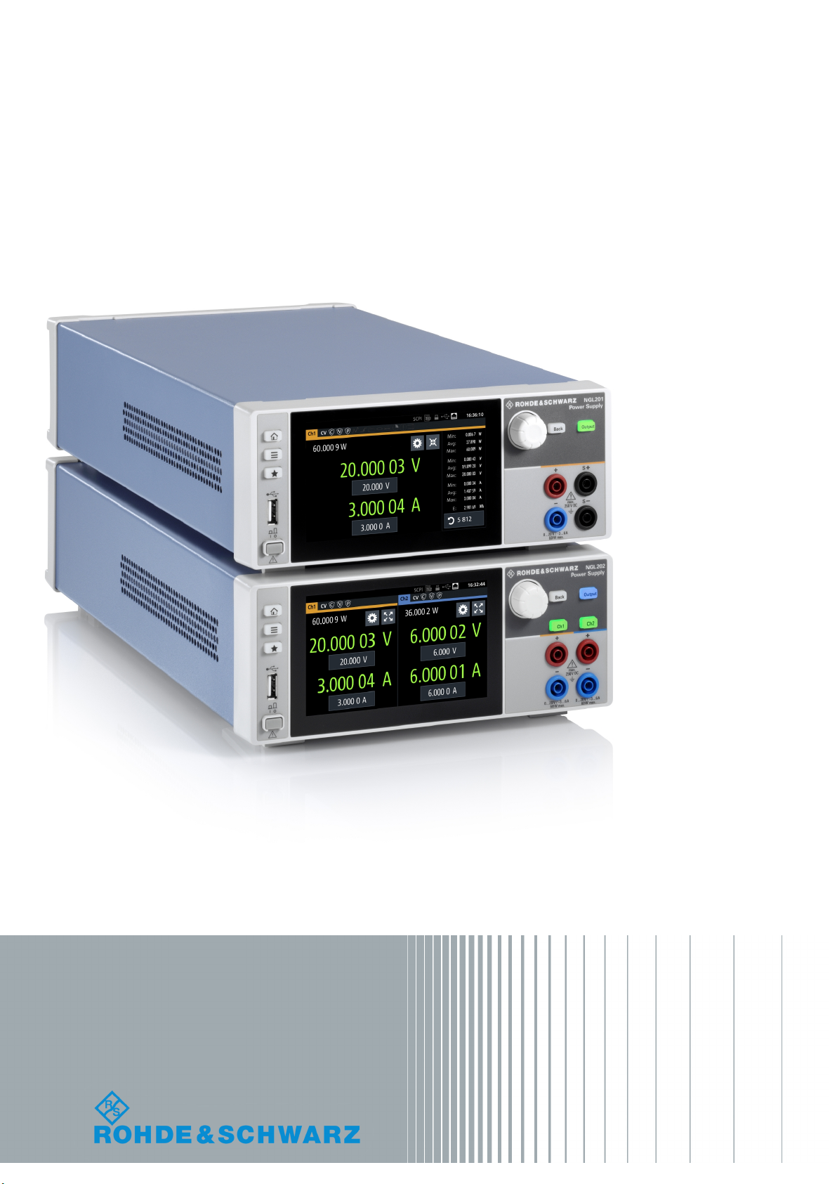
R&S®NGL200
Power Supply
User Manual
(;ÜåT2)
1178873602
User Manual
Version 02.01
Page 2

This manual describes the following R&S®NGL200 models and options:
●
R&S®NGL201 1 Channel PSU 60W (3638.3376.02)
●
R&S®NGL202 2 Channel PSU 120W (3638.3376.03)
●
R&S®NGL-K102 Option Wireless LAN (3652.6362.02)
●
R&S®NGL-K103 Option Digital I/O (3652.6385.02)
●
R&S®NGL-B105 Option GPIB Interface (3652.6356.02)
The contents of this manual correspond to firmware version 1.00 or higher.
The software contained in this product uses several valuable open source software packages. For information, see the "Open
Source Acknowledgment" document, which is available for download from the R&S NGL200 product page at www.rohde-
schwarz.com/product/ngl200 > " Downloads > Firmware ".
Rohde & Schwarz would like to thank the open source community for their valuable contribution to embedded computing.
© 2019 Rohde & Schwarz GmbH & Co. KG
Mühldorfstr. 15, 81671 München, Germany
Phone: +49 89 41 29 - 0
Fax: +49 89 41 29 12 164
Email: info@rohde-schwarz.com
Internet: www.rohde-schwarz.com
Subject to change – Data without tolerance limits is not binding.
R&S® is a registered trademark of Rohde & Schwarz GmbH & Co. KG.
Trade names are trademarks of the owners.
1178.8736.02 | Version 02.01 | R&S®NGL200
Throughout this manual, products from Rohde & Schwarz are indicated without the ® symbol, e.g. R&S®NGL200 is indicated as
R&S NGL200.
Page 3
1
Safety Instructions
Risk of injury and instrument damage
The instrument must be used in an appropriate manner to prevent
electric shock, fire,
●
●
●
●
Keep the "Basic Safety Instructions" and the product documentation
Riesgo de lesiones y daños en el instrumento
El instrumento se debe usar de manera adecuada para p
descargas eléctricas, incendios, lesiones o daños materiales.
●
●
●
especificaciones técnicas pueden contener condiciones adicionales
●
Instrucciones de seguridad
Sicherheitshinweise
Consignes de sécurité
personal injury or instrument damage.
Do not open the instrument casing.
Read and observe the "Basic Safety Instructions" delivered as
printed brochure with the instrument.
Read and observe the safety instructions in the following sections.
Note that the data sheet may specify additional operating conditions.
in a safe place and pass them on to the subsequent users.
No abrir la carcasa del instrumento.
Lea y cumpla las "Instrucciones de seguridad elementales"
suministradas con el instrumento como folleto impreso.
Lea y cumpla las instrucciones de seguridad incluidas en las
siguientes secciones. Se debe tener en cuenta que las
para su uso.
Guarde bien las instrucciones de seguridad elementales, así como
la documentación del producto, y entréguelas a usuarios
posteriores.
revenir
1171.1307.42 - 05
Page 4
2
Gefahr von Verletzungen und Schäden am Gerät
Betreiben Sie das Gerät immer ordnungsgemäß, um elektrischen
Schlag, Brand, Verletzungen von Personen oder Geräteschäden zu
verhindern.
●
●
●
●
Risque de blessures et d'endommagement de l'appareil
L'ap
les électrocutions, incendies, dommages corporels et matériels.
●
●
●
suivantes. Il ne faut pas oublier que la fiche technique peut indiquer
●
Öffnen Sie das Gerätegehäuse nicht.
Lesen und beachten Sie die "Grundlegenden Sicherheitshinweise",
die als gedruckte Broschüre dem Gerät beiliegen.
Lesen und beachten Sie die Sicherheitshinweise in den folgenden
Abschnitten; möglicherweise enthält das Datenblatt weitere
Hinweise zu speziellen Betriebsbedingungen.
Bewahren Sie die "Grundlegenden Sicherheitshinweise" und die
Produktdokumentation gut auf und geben Sie diese an weitere
Benutzer des Produkts weiter.
pareil doit être utilisé conformément aux prescriptions afin d'éviter
N'ouvrez pas le boîtier de l'appareil.
Lisez et respectez les "consignes de sécurité fondamentales"
fournies avec l’appareil sous forme de brochure imprimée.
Lisez et respectez les instructions de sécurité dans les sections
des conditions d’exploitation supplémentaires.
Gardez les consignes de sécurité fondamentales et la
documentation produit dans un lieu sûr et transmettez ces
documents aux autres utilisateurs.
1171.1307.42 - 05
Page 5

Customer Support
Technical support – where and when you need it
For quick, expert help with any Rohde & Schwarz equipment, contact one of our Customer Support
Centers. A team of highly qualified engineers provides telephone support and will work with you to find a
solution to your query on any aspect of the operation, programming or applications of Rohde & Schwarz
equipment.
Up-to-date information and upgrades
To keep your instrument up-to-date and to be informed about new application notes related to your
instrument, please send an e-mail to the Customer Support Center stating your instrument and your wish.
We will take care that you will get the right information.
Europe, Africa, Middle East
North America
Latin America
Asia/Pacific
China
Phone +49 89 4129 12345
customersupport@rohde-schwarz.com
Phone 1-888-TEST-RSA (1-888-837-8772)
customer.support@rsa.rohde-schwarz.com
Phone +1-410-910-7988
customersupport.la@rohde-schwarz.com
Phone +65 65 13 04 88
customersupport.asia@rohde-schwarz.com
Phone +86-800-810-8228 /
+86-400-650-5896
customersupport.china@rohde-schwarz.com
1171.0200.22-06.00
Page 6

R&S®NGL200
1.1 Documentation Overview............................................................................................. 7
1.1.1 Manuals and Instrument Help......................................................................................... 7
1.1.2 Data Sheet...................................................................................................................... 7
1.1.3 Release Notes and Open Source Acknowledgment....................................................... 8
1.2 Conventions Used in the Documentation...................................................................8
1.2.1 Typographical Conventions.............................................................................................8
1.2.2 Conventions for Procedure Descriptions.........................................................................8
1.2.3 Notes on Screenshots.....................................................................................................9
1.2.4 Other Conventions.......................................................................................................... 9
Contents
Contents
1 Preface.................................................................................................... 7
2 Welcome to R&S NGL200....................................................................10
3 Important Notes....................................................................................11
3.1 Symbols....................................................................................................................... 11
3.2 Ambient Conditions.................................................................................................... 11
3.3 Measurement Categories........................................................................................... 12
3.4 Mains Voltage.............................................................................................................. 12
3.5 Limits............................................................................................................................13
4 Getting Started..................................................................................... 14
4.1 Putting into Operation................................................................................................ 14
4.1.1 Safety............................................................................................................................ 15
4.1.2 Intended Operation....................................................................................................... 16
4.1.3 Unpacking and Checking the Instrument...................................................................... 17
4.1.4 Setting Up the Instrument............................................................................................. 18
4.1.4.1 Bench Operation........................................................................................................... 18
4.1.4.2 Rack Mounting.............................................................................................................. 19
4.2 Instrument Tour........................................................................................................... 19
4.2.1 Overview of Controls.....................................................................................................19
4.2.1.1 Front Panel....................................................................................................................19
4.2.1.2 Rear Panel.................................................................................................................... 21
4.2.2 Switching On the Instrument......................................................................................... 23
3User Manual 1178.8736.02 ─ 02.01
Page 7

R&S®NGL200
4.3 Trying Out the Instrument.......................................................................................... 24
4.3.1 Setting the Output Voltage and Current........................................................................ 24
4.3.2 Activating the Channels Output.....................................................................................24
4.4 Maintenance................................................................................................................ 25
5.1 Display Overview........................................................................................................ 26
5.1.1 Status Bar Information.................................................................................................. 26
5.1.2 Channel Display Area................................................................................................... 28
5.2 Using the Touchscreen...............................................................................................30
5.2.1 Using Gestures............................................................................................................. 30
5.2.2 Accessing Functionality in the Home Window.............................................................. 30
5.2.2.1 Settings Button..............................................................................................................30
Contents
5 Operating Basics..................................................................................26
5.2.2.2 Voltage and Current Buttons.........................................................................................31
5.2.2.3 Expand/Collapse Button................................................................................................32
5.2.3 Input Data......................................................................................................................32
5.3 Front Panel Keys.........................................................................................................33
5.3.1 Menu Controls...............................................................................................................34
5.3.1.1 Home Button................................................................................................................. 34
5.3.1.2 Settings Button..............................................................................................................34
5.3.1.3 User Button................................................................................................................... 36
5.3.2 Navigation Controls.......................................................................................................36
5.3.3 Output and Channel Controls........................................................................................37
5.4 Power Derating............................................................................................................37
5.5 Output Modes.............................................................................................................. 37
6 Instrument Functions.......................................................................... 39
6.1 Setting the Channels Voltage and Current............................................................... 39
6.2 Activating the Channels Output................................................................................ 40
6.2.1 Set Constant Resitance................................................................................................ 41
6.2.2 Fast Transient Response.............................................................................................. 42
6.2.3 Output........................................................................................................................... 43
6.3 Protection.................................................................................................................... 45
6.3.1 Over Current Protection (OCP)..................................................................................... 45
6.3.2 Over Voltage Protection (OVP)..................................................................................... 46
4User Manual 1178.8736.02 ─ 02.01
Page 8

R&S®NGL200
6.3.3 Over Power Protection (OPP)....................................................................................... 47
6.3.4 Safety Limits..................................................................................................................48
6.4 Advanced Features..................................................................................................... 49
6.4.1 Arbitrary.........................................................................................................................49
6.4.1.1 Arbitrary Editor.............................................................................................................. 51
6.4.2 Ramp.............................................................................................................................53
6.4.3 Digital I/O...................................................................................................................... 54
6.5 User Button Key.......................................................................................................... 59
6.6 Screenshot...................................................................................................................60
6.7 Data Logger................................................................................................................. 61
6.7.1 CSV Settings.................................................................................................................62
6.8 File Manager................................................................................................................ 64
6.9 Store and Recall ......................................................................................................... 65
Contents
6.10 Interfaces..................................................................................................................... 67
6.10.1 Network Connection......................................................................................................68
6.10.1.1 LAN Connection............................................................................................................ 68
6.10.1.2 Wireless LAN Connection............................................................................................. 70
6.10.2 USB Connection............................................................................................................71
6.10.3 GPIB Address............................................................................................................... 72
6.11 General Instrument Settings......................................................................................73
6.11.1 Licenses........................................................................................................................ 73
6.11.2 Appearance Settings.....................................................................................................75
6.11.3 Sound Settings..............................................................................................................75
6.11.4 Date and Time...............................................................................................................76
6.11.5 Device Information........................................................................................................ 77
6.11.6 Update Device...............................................................................................................77
7 Remote Control Commands................................................................79
7.1 Common Setting Commands.....................................................................................79
7.2 System Settings Commands......................................................................................82
7.3 Display Commands.....................................................................................................84
7.4 Trigger Commands..................................................................................................... 85
7.5 Configuration Commands.......................................................................................... 85
7.5.1 Channel Selection......................................................................................................... 85
5User Manual 1178.8736.02 ─ 02.01
Page 9

R&S®NGL200
7.5.2 Voltage Setting..............................................................................................................87
7.5.3 Current Setting.............................................................................................................. 91
7.5.4 Resistance Setting........................................................................................................ 95
7.5.5 Combined Setting of Voltage and Current Setting........................................................ 97
7.5.6 Output Setting............................................................................................................... 98
7.5.7 Fuse Setting................................................................................................................ 102
7.5.8 OVP Setting................................................................................................................ 106
7.5.9 OPP Setting................................................................................................................ 109
7.6 Measurement Commands.........................................................................................112
7.7 Arbitrary Setting Commands................................................................................... 113
7.8 Advanced Operating Commands.............................................................................118
7.8.1 Ramp...........................................................................................................................118
7.9 Data and File Management Commands.................................................................. 119
Contents
7.10 Status Reporting....................................................................................................... 127
7.10.1 STATus:OPERation Registers.....................................................................................127
7.10.2 STATus:QUEStionable Registers................................................................................ 129
Annex.................................................................................................. 132
A Additional Basics on Remote Control..............................................132
A.1 Messages and Command Structure........................................................................ 132
A.1.1 Messages....................................................................................................................132
A.1.2 SCPI Command Structure...........................................................................................133
A.2 Command Sequence and Synchronization............................................................ 137
A.2.1 Preventing Overlapping Execution..............................................................................137
A.3 Status Reporting System......................................................................................... 137
A.3.1 Structure of a SCPI Status Register............................................................................138
List of Commands..............................................................................143
Index....................................................................................................146
6User Manual 1178.8736.02 ─ 02.01
Page 10

R&S®NGL200
1.1 Documentation Overview
1.1.1 Manuals and Instrument Help
Preface
Documentation Overview
1 Preface
This section provides an overview of the R&S NGL200 user documentation.
You find the manuals on the product page at:
www.rohde-schwarz.com/product/ngl200
Getting started manual
Introduces the R&S NGL200 and describes how to set up the product. A printed English version is included in the delivery.
User manual
Contains the description of all instrument modes and functions. It also provides an
introduction to remote control, a complete description of the remote control commands
with programming examples, and information on maintenance and instrument interfaces. Includes the contents of the getting started manual.
The online version of the user manual provides the complete contents for immediate
display on the internet.
Basic safety instructions
Contains safety instructions, operating conditions and further important information.
The printed document is delivered with the instrument.
Service manual
Describes the performance test for checking the rated specifications, module replacement and repair, firmware update, troubleshooting and fault elimination, and contains
mechanical drawings and spare part lists. The service manual is available for registered users on the global Rohde & Schwarz information system (GLORIS, https://
gloris.rohde-schwarz.com).
1.1.2 Data Sheet
The data sheet contains the technical specifications of the R&S NGL200. It also lists
the options with their order numbers and optional accessories.
See www.rohde-schwarz.com/brochure-datasheet/ngl200
7User Manual 1178.8736.02 ─ 02.01
Page 11
R&S®NGL200
1.1.3 Release Notes and Open Source Acknowledgment
1.2 Conventions Used in the Documentation
1.2.1 Typographical Conventions
Preface
Conventions Used in the Documentation
The release notes list new features, improvements and known issues of the current
firmware version, and describe the firmware installation. The open source acknowledgment document provides verbatim license texts of the used open source software.
See www.rohde-schwarz.com/firmware/ngl200. The open source acknowledgment
document can also be read directly on the instrument.
The following text markers are used throughout this documentation:
Convention Description
"Graphical user interface elements"
[Keys] Key and knob names are enclosed by square brackets.
Filenames, commands,
program code
Input Input to be entered by the user is displayed in italics.
Links Links that you can click are displayed in blue font.
"References" References to other parts of the documentation are enclosed by quota-
All names of graphical user interface elements on the screen, such as
dialog boxes, menus, options, buttons, and softkeys are enclosed by
quotation marks.
Filenames, commands, coding samples and screen output are distinguished by their font.
tion marks.
1.2.2 Conventions for Procedure Descriptions
When operating the instrument, several alternative methods may be available to perform the same task. In this case, the procedure using the touchscreen is described.
Any elements that can be activated by touching can also be clicked using an additionally connected mouse. The alternative procedure using the keys on the instrument or
the on-screen keyboard is only described if it deviates from the standard operating procedures.
The term "select" may refer to any of the described methods, i.e. using a finger on the
touchscreen, a mouse pointer in the display, or a key on the instrument or on a keyboard.
8User Manual 1178.8736.02 ─ 02.01
Page 12

R&S®NGL200
1.2.3 Notes on Screenshots
1.2.4 Other Conventions
Preface
Conventions Used in the Documentation
When describing the functions of the product, we use sample screenshots. These
screenshots are meant to illustrate as many as possible of the provided functions and
possible interdependencies between parameters. The shown values may not represent
realistic usage scenarios.
The screenshots usually show a fully equipped product, that is: with all options installed. Thus, some functions shown in the screenshots may not be available in your particular product configuration.
Remote commands may include abbreviations to simplify input. In the description of
such commands, all parts that have to be entered are written in capital letters.
Additional text in lowercase characters is for information only.
9User Manual 1178.8736.02 ─ 02.01
Page 13

R&S®NGL200
Welcome to R&S NGL200
2 Welcome to R&S NGL200
The one or two-channel power supply series are based on a classical transformer concept with linear regulators. This concept allows the instrument to achieve highest accuracy and lowest residual ripple.
The R&S NGL200 power supply series feature galvanically isolated, floating overload
and short-circuit proof outputs. The outputs can be connected in parallel and serial to
get higher voltages, thus making high currents available.
Multi-purpose protection functions are available for each channel which you can set
separately, such as overcurrent protection (OCP), overvoltage protection (OVP) and
overpower protection (OPP). If such a limit is reached, the affected output channel is
automatically turned off and an indicator icon ( , , ) blinks on the display. In the
case of two-channel power supply, NGL202, the overcurrent protection can be linked to
the other channel. In this case, the linked channel is turned off when the other channel
reaches a limit.
Additionally, the R&S NGL200 is protected with overtemperature protection (OCP).
This safey feature protects the R&S NGL200 from getting overheated, when activated,
the channel outputs are turned off.
The Arbitrary function allows a freely definable voltage and current sequences with a
timeframe as short as 10 ms. It allows you to vary the voltage or current limit during a
test sequence, for example to simulate different charging conditions of a battery. With
Ramp function, the R&S NGL200 provides the operating condition to simulate the continuous rise of the supply voltage within a defined timeframe of 10 ms to 10 s.
All R&S NGL200 power supply series are equipped with a color LCD display (800 x
480 pixels). The R&S NGL200 comes with a USB and LAN (LXI) interface. Equipped
with a wireless LAN (WLAN) option, you can establish a network connection wirelessly .
The digital I/O interfaces installed at the rear panel is activated with an option, it provides a set of 4-bit digital interfaces that can be individually used as trigger inputs or
outputs.
The user manual contains description of the functionalities that the instrument provides. The latest version is available for download at the product homepage (http://
www.rohde-schwarz.com/product/ngl200).
10User Manual 1178.8736.02 ─ 02.01
Page 14
R&S®NGL200
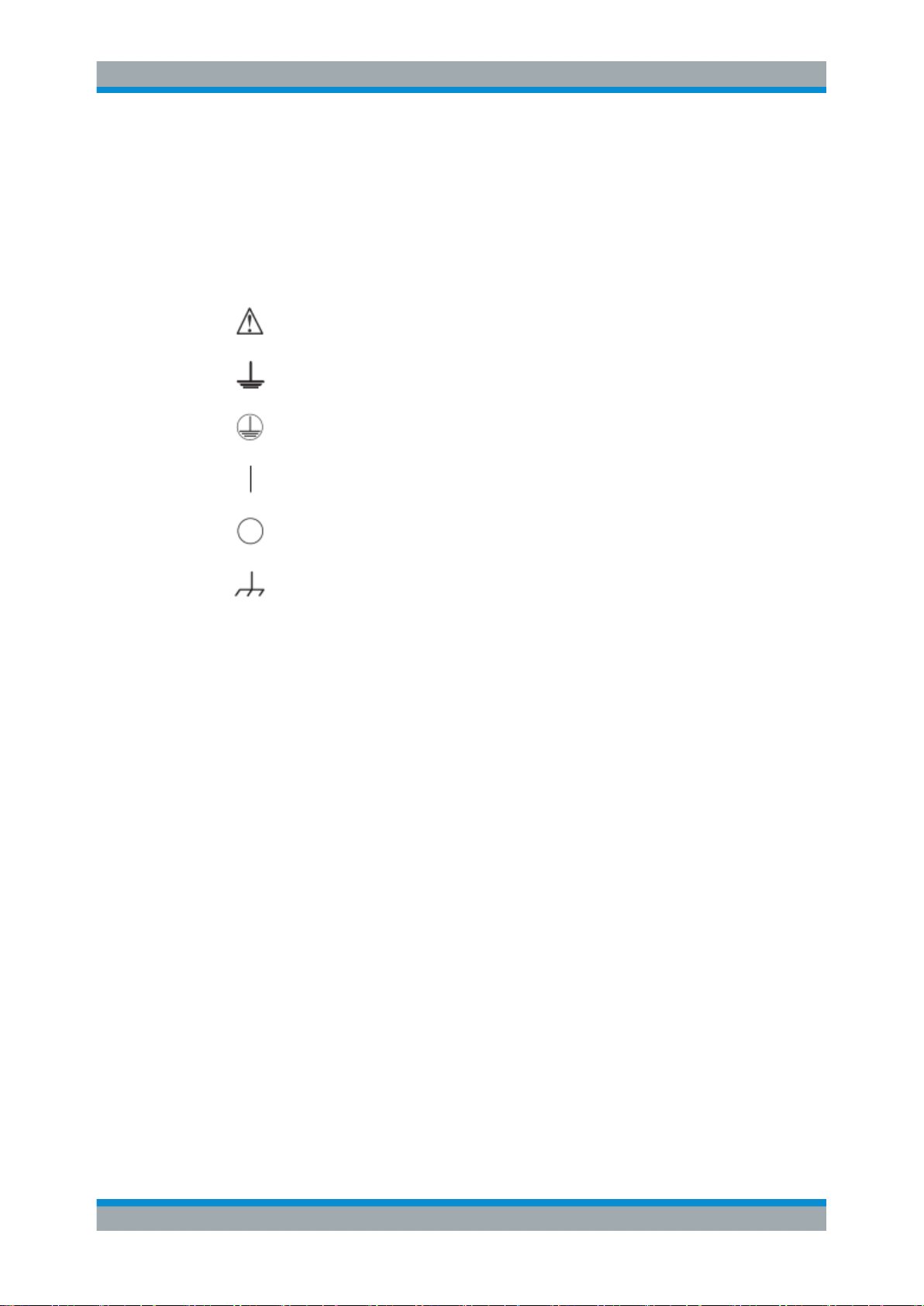
3.1 Symbols
Important Notes
Ambient Conditions
3 Important Notes
Caution, general danger zone
Ground
PE terminal
ON (supply voltage)
OFF (supply voltage)
Ground terminal
3.2 Ambient Conditions
The allowed operating temperature ranges from +5 °C to +40 °C (pollution category 2).
The maximum relative humidity (without condensation) is at 80 %.
During storage and transport, the temperature must be between -40 °C and +70 °C. In
case of condensation during transportation or storage, the instrument will require
approximately two hours to dry and reach the appropriate temperature prior to operation. The instrument is designed for use in a clean and dry indoor environment. Do not
operate with high dust and humidity levels, if danger of explosion exists or with aggressive chemical agents.
Any operating position may be used; however adequate air circulation must be maintained. For continuous operation, a horizontal or inclined position (integrated stand) is
preferable.
Specifications with tolerance data apply after a warm up period of at least 30 minutes
at a temperature of 23 °C (tolerance -3 °C/+ 7 °C).
The heat produced inside the instrument is guided to the exterior via temperature-controlled fan. Each channel has multiple temperature sensors which check the heat generation in the instrument and control the fan speed.
It is necessary to ensure that there is sufficient space around the instrument sides for
heat exchange. If the temperature inside the instrument increases to more than
11User Manual 1178.8736.02 ─ 02.01
Page 15

R&S®NGL200
3.3 Measurement Categories
Important Notes
Mains Voltage
~72 °C, a channel-specific overheat protection intervenes. Affected outputs will automatically be switched off.
Air circulation
Do not obstruct the ventilation holes!
This instrument is designed for supplying power on circuits that are only indirectly connected to the low voltage mains or not connected at all. The instrument is not intended
for measurements within the measurement categories II, III or IV; the maximum potential against earth generated by the user must not exceed 250 V peak in this application.
The following information refers solely to user safety. Other aspects, such as the maximum voltage, are described in the technical data and must also be observed.
The measurement categories refer to transients that are superimposed on the mains
voltage. Transients are short, very fast (steep) current and voltage variations which
may occur periodically and non-periodically. The level of potential transients increases
as the distance to the source of the low voltage installation decreases.
●
Measurement CAT IV: Measurements at the source of the low voltage installations
(e.g. meters)
●
Measurement CAT III: Measurements in building installations (e.g. power distribution installations, power switches, firmly installed sockets, firmly installed engines
etc.)
●
Measurement CAT II: Measurements on circuits electronically directly connected to
the mains (e.g. household appliances, power tools, etc.)
●
0 (instruments without measured measurement category): Other circuits that are
not connected directly to the mains
3.4 Mains Voltage
The instrument applies 50 Hz / 60 Hz mains voltages ranging from 100 VAC, 115 VAC
or 230 VAC (tolerance ± 10 %). Mains voltage switching is not intended. The input line
fuse is accessible externally. Power socket and fuse holder form a single unit.
You need to first disconnect the power cord from the connector before you can safely
replace the fuse (as long as the fuse holder is undamaged). Next, the fuse holder must
be pried out using a screwdriver. The starting point is a slot next to the contacts. The
fuse can then be forced out of its mounting and must be replaced with an identical fuse
(see information about the fuse type on the rear panel). The fuse holder will be inserted
against the spring pressure until it locks into place. The use of mended fuses or short
12User Manual 1178.8736.02 ─ 02.01
Page 16
R&S®NGL200
3.5 Limits
Important Notes
Limits
circuiting the fuse holder is prohibited. Resulting damages are not covered by the warranty.
Safe operation
If the instrument is to remain unattended for a longer time period, it must be switched
off at the mains switch for safety reasons.
The R&S NGL200 is equipped with a protective overload feature. The protective overload feature prevents damage to the instrument and is intended to protect against a
possible electrical shock. The maximum values for the instrument must not be exceeded. The protection limits are listed on the front panel of the R&S NGL200 to ensure
the safe operation of the instrument.
These protection limits must be adhered to:
Specification Limits
Maximum output voltage 20 VDC
Maximum output current 6 A (<= 6 V)
3 A (> 6 V)
Maximum voltage against earth 250 V peak
MAximum counter-voltage (same polarity) 22 V
Maximum reverse voltage (opposite polarity) 0.5 V
Maximum reverse current sink current 3 A
Power supply 100 VAC, 115 VAC or 230 VAC (tolerance ± 10%)
Frequency 50 Hz/60 Hz
Maximum power output 120 W (R&S NGL202), 60 W (R&S NGL201)
13User Manual 1178.8736.02 ─ 02.01
Page 17
R&S®NGL200
4.1 Putting into Operation
Getting Started
Putting into Operation
4 Getting Started
This chapter describes the steps to set up the R&S NGL200 for the first time.
Risk of injury and instrument damage
The instrument must be used in an appropriate manner to prevent electric shock, fire,
personal injury, or damage.
●
Do not open the instrument casing
●
Read and observe the "Basic Safety Instructions" delivered as a printed brochure
with the instrument. Note that the basic safety instructions also contain information
on operating conditions that prevent damage to the instrument
In addition, read and observe the safety instructions in the following sections.
Notice that the data sheet may specify additional operating conditions.
Risk of radio interference
This instrument is compliant with Class A of CISPR 32. In a residential environment,
this instrument may cause radio interference.
Risk of instrument damage during operation
An unsuitable operating site or test setup can cause damage to the instrument and the
connected devices. Ensure the following operating conditions before you switch on the
instrument:
●
The instrument is dry and shows no sign of condensation
●
The instrument is positioned as described in Chapter 4.1.4.1, "Bench Operation",
on page 18
●
The ambient temperature does not exceed the range specified in the data sheet
●
Signal levels at the input connectors are all within the specified ranges
●
Signal outputs are correctly connected and not overloaded
14User Manual 1178.8736.02 ─ 02.01
Page 18
R&S®NGL200
4.1.1 Safety
Getting Started
Putting into Operation
EMI impact on measurement results
Electromagnetic interference (EMI) may affect the measurement results.
To suppress the generated EMI:
●
Use suitable shielded cables of high quality, for example, LAN cables
●
Note the EMC classification in the data sheet
● Safety......................................................................................................................15
● Intended Operation................................................................................................. 16
● Unpacking and Checking the Instrument................................................................ 17
● Setting Up the Instrument....................................................................................... 18
This instrument was built in compliance with DIN EN 61010-1 (VDE 0411 part 1),
safety regulations for electrical instruments, control units and Iaboratory equipment.
It has been tested and shipped from the plant in safe condition. It is also in compliance
with the regulations of the European standard EN 61010-1 and the international standard IEC 61010-1.
To maintain this condition and ensure safe operation, you must observe all instructions
and warnings given in this user manual. Casing, chassis and all measuring ports are
connected to a protective earth conductor. The instrument is designed in compliance
with the regulations of protection class I.
For safety reasons, the instrument may only be operated with authorized safety sockets. The power cord must be plugged in before signal circuits may be connected.
Never use the product if the power cable is damaged. Check regularly if the power
cables are in perfect condition. Choose suitable protective measures and installation
types to ensure that the power cord cannot be damaged and that no harm is caused by
tripping hazards or from electric shock, for instance.
Risk of electric shock
It is prohibited to disconnect the earthed protective connection inside or outside of the
instrument!
If it is assumed that a safe operation is no longer possible, the instrument must be shut
down and secured against any unintended operation.
Safe operation can no longer be assumed as follows:
●
Instrument shows visible damage
●
Instrument includes loose parts
●
Instrument no longer functions properly
15User Manual 1178.8736.02 ─ 02.01
Page 19
R&S®NGL200
Getting Started
Putting into Operation
– After an extended period of storage under unfavorable conditions (e.g. out-
doors or in damp rooms)
– After rough handling during transport (e.g. packaging that does not meet the
minimum requirements by post office, railway or forwarding agency)
Exceeding the low voltage protection
Use insulated wires and not bare wires for the terminal connection.
It is assumed that only qualified and trained personnel service the power supplies and
the connected loads.
Prior to switching on the product, it must be ensured that the nominal voltage setting
on the product matches the nominal voltage of the AC supply network. If it is necessary
to set a different voltage, the power fuse of the product may have to be changed
accordingly.
4.1.2 Intended Operation
The instrument is intended only for use by personnel familiar with the potential risks of
measuring electrical quantities.
For safety reasons, the instrument may only be connected to properly installed wall
outlets. Separating the ground is prohibited.
The power plug must be inserted before signal circuits may be connected.
Use only the power cord included in the delivery package. See "Delivery package"
on page 18.
Before each measurement, measuring cables must be inspected for damage and
replaced if necessary. Damaged or worn components can damage the instrument or
cause injury.
The product may be operated only under the operating conditions and in the positions
specified by the manufacturer, without the product's ventilation being obstructed. If the
manufacturer’s specifications are not observed, this can result in electric shock, fire
and / or serious personal injury, and in some cases, death.
Applicable local or national safety regulations and rules for the prevention of accidents
must be observed in all work performed.
The instrument is designed for use in the following sectors: Industrial, residential, business and commercial areas and small businesses.
The instrument is designed for indoor use only. Before each measurement, you need
to verify at a known source if the instrument functions properly.
16User Manual 1178.8736.02 ─ 02.01
Page 20
R&S®NGL200
Getting Started
Putting into Operation
To disconnect from the mains, unplug the IEC socket on the back panel.
See Table 4-1 for the general data on the instrument specification. For more informa-
tion, see the instrument datasheet (PN: 5216.1057.12).
Table 4-1: General data on instrument specification
General data
Mains nominal voltage AC 100 / 115 / 230 V (±10 %) 50 Hz to 60 Hz
Maximum input power 400 W
Mains fuses IEC 60127-2 / 5 T4.0H 250 V
Operating temperature range +5 °C to +40 °C
Storage temperature range -20 °C to +70 °C
Humidity Non-condensing 5 % to 80 %
Display 5 " (Resolution 800 x 480, WVGA)
Input Method Capacitive touch input
Rack mount capability R&S HZN96 rack adapter 2U (P/N: 3638.7813.02)
Dimensions (W x H x D) 222 mm x 97 mm x 436 mm (8.74 in x 3.82 in x 17.17 in)
Weight R&S NGL201 7.1 kg (15.65 lb)
R&S NGL202 7.3 kg (16.09 lb)
4.1.3 Unpacking and Checking the Instrument
Unpack the R&S NGL200 carefully and check the content of the package.
●
Check the equipment for completeness using the delivery note and package contents list for the various items.
●
Check the instrument for any damage and loose parts. If there is any damage,
immediately contact the carrier who delivered the instrument.
Packing material
Retain the original packing material. If the instrument needs to be transported or shipped at a later date, you can use the material to protect the control elements and connectors.
17User Manual 1178.8736.02 ─ 02.01
Page 21
R&S®NGL200
Getting Started
Putting into Operation
Risk of damage during transportation and shipment
Insufficient protection against mechanical and electrostatic effects during transportation
and shipment can damage the instrument.
●
Always ensure that sufficient mechanical and electrostatic protection are provided
●
When shipping an instrument, the original packaging should be used. If you do not
have the original packaging, use sufficient padding to prevent the instrument from
moving around inside the box. Pack the instrument in antistatic wrap to protect it
from electrostatic charging
●
Secure the instrument to prevent any movement and other mechanical effects during transportation
Delivery package
The package contents contain the following items:
●
R&S NGL200 power
●
Four power cables
●
One printed Getting Started manual
●
One document folder containing a printed Basic Safety Instructions
4.1.4 Setting Up the Instrument
The R&S NGL200 is designed for benchtop and rackmount.
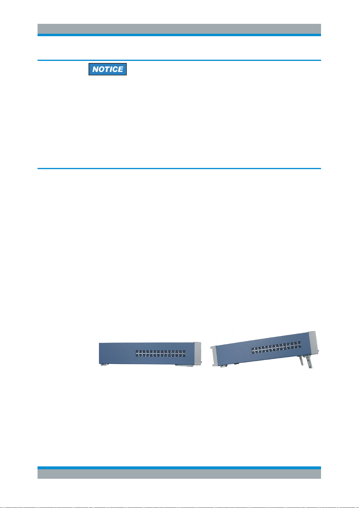
4.1.4.1 Bench Operation
On a benchtop, the R&S NGL200 can either lie flat or stand on its feet. As shown in
Figure 4-1, feet on the bottom can be folded out to set the instrument in an inclined
position.
Figure 4-1: Operating positions
18User Manual 1178.8736.02 ─ 02.01
Page 22
R&S®NGL200
4.1.4.2 Rack Mounting
Getting Started
Instrument Tour
Positioning of instrument
The instrument must be positioned in a manner that allows the user to disconnect the
unit from the mains at any time and without restrictions.
The instrument can be installed in a 19 " rack-mount using a rack adapter kit.
Ambient temperature
Place the R&S NGL200 in an area where the ambient temperature is within +5 °C to
+40 °C. The R&S NGL200 is fan-cooled and must be installed with sufficient space
along the sides to ensure free flow of air.
4.2 Instrument Tour
This chapter provides an overview of all the controls available in the R&S NGL200
models and steps to switch on the instrument for the first time.
● Overview of Controls...............................................................................................19
● Switching On the Instrument...................................................................................23
4.2.1 Overview of Controls
4.2.1.1 Front Panel
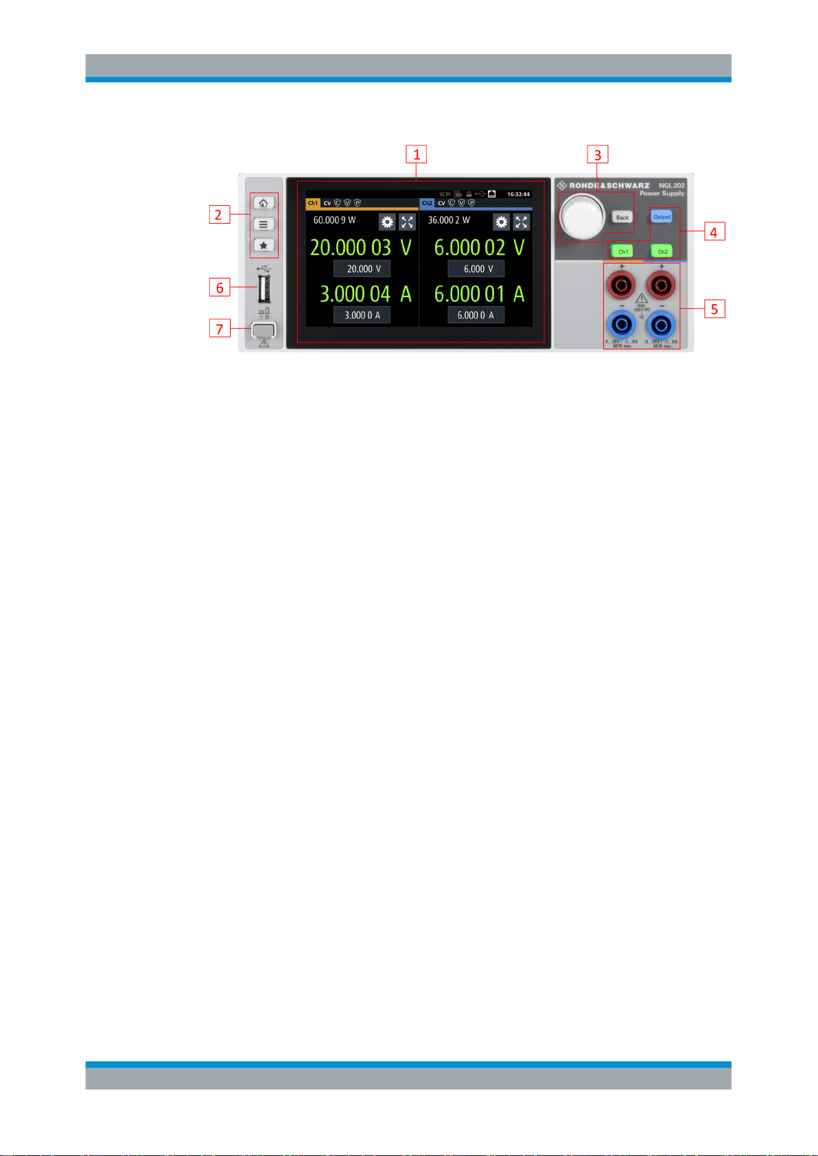
The front panel of the R&S NGL200 is as shown in Figure 4-2. The function keys and
navigation controls are located beside the display. The various connectors are located
right of the display.
The R&S NGL200 has one output channel for NGL201 model and two output channels
for NGL202 model .
19User Manual 1178.8736.02 ─ 02.01
Page 23
R&S®NGL200
Getting Started
Instrument Tour
Figure 4-2: Front panel of R&S NGL200
1 = Display with touch screen
2 = Menu control keys
3 = Navigation keys
4 = Output and channels keys
5 = Output terminals (one channel with sense NGL201, two channels NGL202)
6 = USB connector
7 = Power key
Display (1)
The display is a color LCD screen. Depending on the instrument model, up to two
channels are shown on the display. The respective measurement settings and functions are displayed in the individual channel display area. There is a status bar in the
device level and channel level, showing the device operating mode and respective
channel settings of the instrument.
For a detailed description on-screen layout, see section "Display Overview" in the User
Manual.
Menu control keys (2)
The menu control keys allow you to navigate to the home window, main menu window
and user button key in the instrument.
For a detailed description on navigation keys, see section "Menu Controls" in the User
Manual.
Navigation keys (3)
The navigation keys are used for menu navigation and value adjustment in the instrument.
For a detailed description on navigation, see section "Navigation Controls" in the User
Manual.
Output and channel keys (4)
Depending on the instrument type, up to two output channels are available to source or
sink power to and from the output terminals.
20User Manual 1178.8736.02 ─ 02.01
Page 24
R&S®NGL200
Getting Started
Instrument Tour
Each channel is capable to source 0 V to 6 V with a current of 6 A or 6 V to 20 V with a
current of 3 A. In sink mode, each channel can consume 0 A to 3 A at an input voltage
of 0 V to 20 V.
Output terminals (5)
Both instrument models are equipped with 4 terminals. The R&S NGL201 provides
both the output plus the sense connectors at the front panel while the R&S NGL202
provides only output terminals for both channels.
USB connector (6)
The USB connector is a Type-A connector. You can connect a USB flash drive to this
connector to perform a firmware update, store logging data or screen shots.
Power key (7)
The [Power] key switches the instrument on and off.
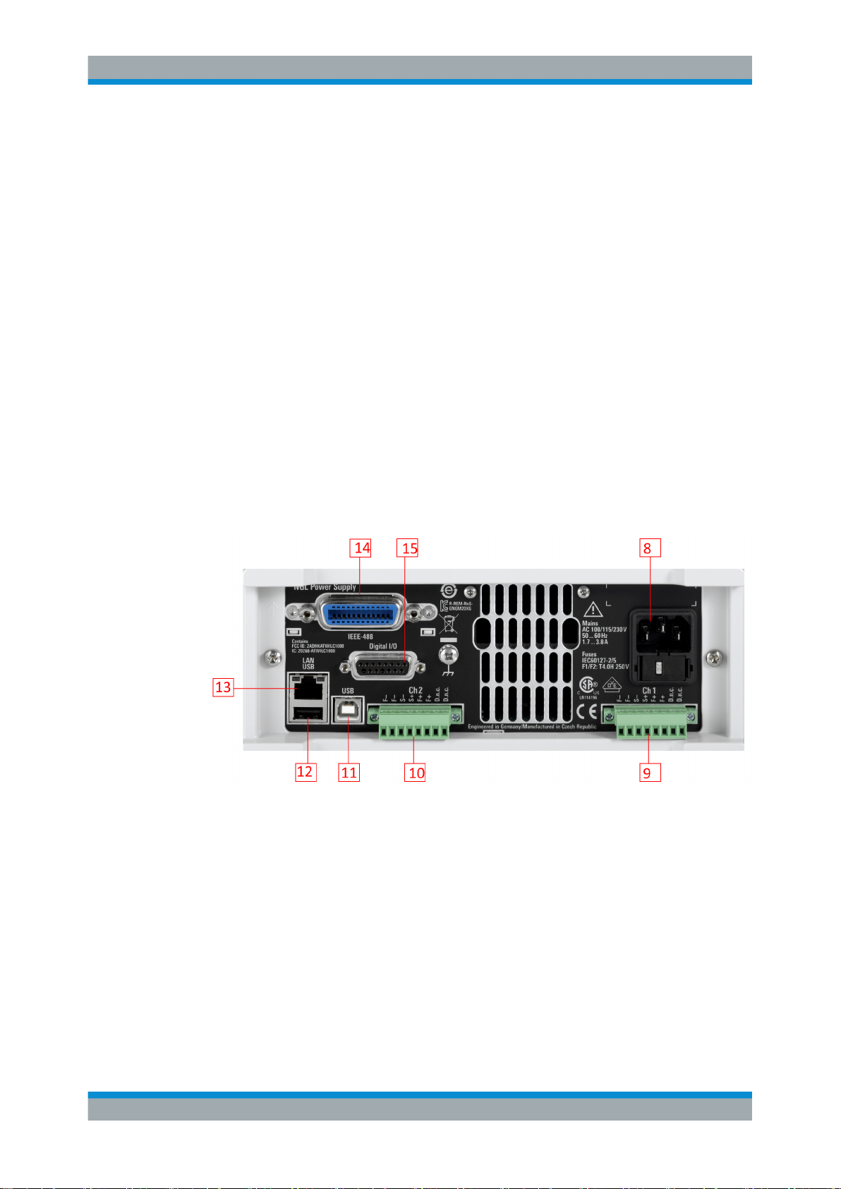
4.2.1.2 Rear Panel
Figure 4-3 shows the rear panel of the R&S NGL200 with its connectors.
Figure 4-3: Rear panel of R&S
8 = AC inlet with fuse holder and voltage selector
9 = Channel 1 rear panel connector
10 = Channel 2 rear panel connector (NGL202 model)
11 = USB connector (Device)
12 = USB connector (Host)
13 = Ethernet (LAN) connector
14 = Cover for optional IEEE 488 (GPIB) Interface
15 = Digital I/O connector
NGL200
21User Manual 1178.8736.02 ─ 02.01
Page 25
R&S®NGL200
Getting Started
Instrument Tour
AC inlet with fuse holder and voltage selector (8)
Main supply cord
Do not use detachable mains supply cord with inadequate rating.
For safety reasons, the instrument can only be operated with authorized safety sockets.
The power cable must be plugged in before signal circuits can be connected. Never
use the product if the power cable is damaged. See Chapter 4.2.2, "Switching On the
Instrument", on page 23 for more information.
The built-in voltage selector selects the mains voltage between 100 V, 115 V and 230
V. All voltage settings are using the same fuse rating.
Channel connectors (9, 10)
Output Terminals
Either the output terminals at the front panel or those at the back panel can be used.
Using both terminals at the same time can cause instrument malfunction.
DVM pins on the channel connector are only available in the NGM types power supply.
The channel connectors contain both output ("F+", "F-") and sense ("S+", "S-") connections. Connector for "Ch 2" is only available in the R&S NGL202 model.
USB connectors (11, 12)
The USB host connector (Type-A) can be used for mass storage devices like the USB
connector at the front panel.
The USB device connector is a Type-B connector for remote control operation.
Ethernet connector (13)
This connector is used for establishing remote control via SCPI.
See section "Ethernet Setup" in the user manual for more information on the connection setup.
Option GPIB interface (14)
An IEEE488 GPIB interface can be ordered (NGL-B105). This interface is not user
installable.
22User Manual 1178.8736.02 ─ 02.01
Page 26
R&S®NGL200
4.2.2 Switching On the Instrument
Getting Started
Instrument Tour
Digital I/O connector (15)
The Digital I/O connector is a terminal block for external input or output.
The Digital Trigger I/O option (NGL-K103) must be installed for this function to be available in the instrument.
Before switching on the instrument, check if the value on the voltage selector corresponds to the mains voltage (100 V, 115 V or 230 V). Switch it on, if necessary.
Fuse rating
The R&S NGL200 is using the same fuse ratings for all main voltages.
To change power fuse:
1. Peel off the yellow label sticker on the AC inlet.
2. Release the latch of the fuse holder which is located directly below the socket and
pull it out.
3. Pull out the removable part of the fuse holder.
4. Turn this part until correct voltage label (100, 115 or 230) is displayed in the window of the holder.
5. Return the fuse holder to its position in the panel.
To switch on instrument:
1. Connect the power cable to the AC power connector on the rear panel of the
R&S NGL200.
2. Connect the power cable to the socket outlet.
3. Press [Power] key on the front panel.
The instrument performs a system check, boots the operating system, and starts
the R&S NGL200 firmware.
By default, all output channels are turned off when the instrument is switched on to
prevent connected loads from being damaged unintentionally.
During startup, the R&S NGL200 is loaded with the last saved instrument settings from
internal memory. See Chapter 6.9, "Store and Recall ", on page 65.
To switch off instrument:
1. Press [Power] key.
All current settings are saved to internal memory and the firmware shutdown.
23User Manual 1178.8736.02 ─ 02.01
Page 27
R&S®NGL200
4.3 Trying Out the Instrument
Getting Started
Trying Out the Instrument
2. Disconnect the AC power cable from the AC power supply.
This chapter describes some basic functions that you can perform with the
R&S NGL200.
Source and sink current
The R&S NGL200 series are 2 quadrant power supplies which may both source and
sink current. This function needs no separate configuration or mode switching. As soon
as the voltage across the output terminal exceeds the set voltage, current flows into
the instrument. This is an intended feature and it is safe.
On the display, sink mode is shown as negative current.
4.3.1 Setting the Output Voltage and Current
1. Press [Home] key.
The R&S NGL200 displays the home window.
2. Select voltage or current parameter in the home window
The R&S NGL200 displays an on-screen keypad to set the value.
3. Enter the required value.
4. Confirm value with the unit key (for voltage - V or mV, for current A or mA).
4.3.2 Activating the Channels Output
The output voltages can be switched on or off regardless of the operating mode the
instrument is in.
To switch on or off channel output.
1. Select desired channel key ([Ch1] or [Ch2]) on the front panel.
2. Press [Output] key.
The R&S NGL200 output the set voltage level on the selected output channel terminal.
Depending on the mode which the channels are operated in, the followings are
observed:
24User Manual 1178.8736.02 ─ 02.01
Page 28
R&S®NGL200
Getting Started
Maintenance
CR mode
CR mode is a special case of sink mode in which the instrument behaves like a constant resistor. Only in this mode, the respective channel keys and display font color in
the home window turns cyan.
In "normal" sink mode, the colors are the same as in source mode: green if the current
flowing into the R&S NGL200 is below the set current and red if the current is limited to
the set value. The only visible indication of sink mode is the change of the sign of the
current readout change to "Minus".
Color illuminated on front panel keys and display
font color of voltage and current in home window
Green Constant voltage mode (CV)
Red Constant current mode (CC)
Cyan Constant resistance mode (CR)
Also, the operating symbol mode (CV, CC or CR) is displayed at the channel status bar
of the respective channel.
4.4 Maintenance
Before cleaning the instrument, ensure that it has been switched off and power cable is
disconnected.
Clean the outer case of the instrument at regular intervals, using a soft, lint-free dust
cloth.
Operating mode
Note: Instrument is operated in sink mode and
"Constant Resistance" is activated.
Instrument damage caused by cleaning agents
Cleaning agents contain substances that may damage the instrument. For example,
cleaning agents that contain a solvent may damage the front panel labeling, plastic
parts, or the display.
Never use cleaning agents such as solvents (thinners, acetone, etc.), acids, bases, or
other substances.
The display may only be cleaned with an appropriate glass cleaner. Rub the display
down with a dry, clean and lint-free cloth. Do not allow cleaning fluid to enter the instrument.
25User Manual 1178.8736.02 ─ 02.01
Page 29
R&S®NGL200
5.1 Display Overview
Operating Basics
Display Overview
5 Operating Basics
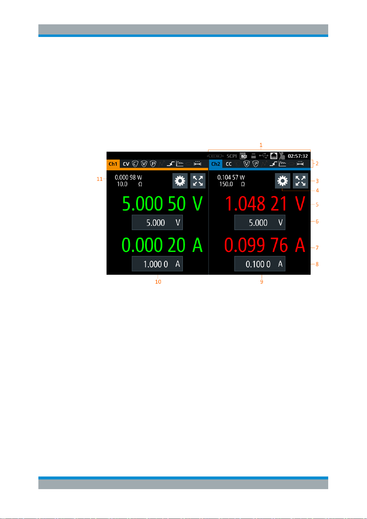
The following displays the home window of R&S NGL200. It shows the output voltage
and current level, status bar information and control settings of the instrument.
Figure 5-1: Home window of R&S NGL200 with 2 channels
1 = Device status bar
2 = Channel status bar
3 = Expand/Collapse channel button
4 = Settings button
5 = Output voltage level
6 = Set voltage level
7 = Output current level
8 = Set current level
9 = Channel display area of Ch2
10 = Channel display area of Ch1
11 = Output power measurement
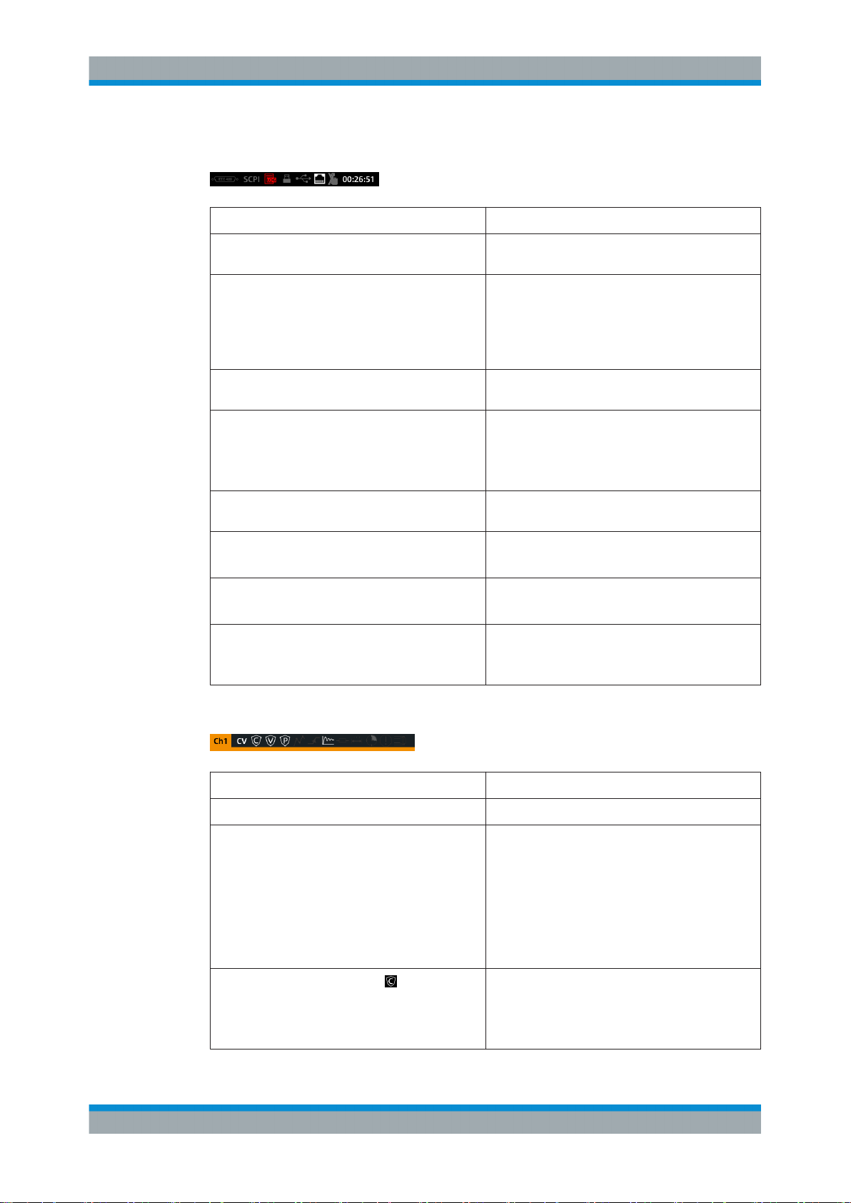
5.1.1 Status Bar Information
There are two levels of status bar information. One is the device status information and
the other is the individual channel status information.
26User Manual 1178.8736.02 ─ 02.01
Page 30
R&S®NGL200
Operating Basics
Display Overview
Device status bar
Function Description
GPIB/IEEE488 interface If GPIB/IEEE488 interface is installed, the icon is
highlighted in white.
SCPI command If active, the icon is highlighted in white.
If an error is in the remote command, the icon is
highlighted in red.
See Chapter 7, "Remote Control Commands",
on page 79.
USB host interface If USB stick is present, the icon is highlighted in
white.
Data Logger If data logging is present, the icon is highlighted in
white.
If an error is present, the icon is highlighted in red.
See Chapter 6.7, "Data Logger", on page 61.
USB device interface If a host command is received in USB interface, the
icon is highlighted in white.
Ethernet/LAN interface If active, the icon is highlighted in white.
See Chapter 6.10, "Interfaces", on page 67.
Time Display of time in hh:mm:ss format.
See Chapter 6.11.4, "Date and Time", on page 76.
Touchscreen If disabled, the icon is highlighted in white.
See Chapter 5.2, "Using the Touchscreen",
on page 30.
Channel status bar
Function Description
Channel number Indication of channel 1 or channel 2 display.
Operation mode The R&S NGL200 has three operating modes:
●
CV: Constant voltage mode
●
CC: Constant current mode
●
CR: Constant resistance mode. The
R&S NGL200 goes into this mode when operates in sink mode and the "Constant Resistance" mode is activated.
For more information, see Chapter 5.5, "Output
Modes", on page 37.
"Over Current Protection" (OCP),
If enabled, the icon is highlighted in white.
If triggered, the icon blinks.
See Chapter 6.3.1, "Over Current Protection
(OCP)", on page 45.
27User Manual 1178.8736.02 ─ 02.01
Page 31

R&S®NGL200
Operating Basics
Display Overview
Function Description
"Over Voltage Protection" (OVP),
"Over Power Protection" (OPP),
"Arbitary Editor" mode,
"Ramp" mode,
"Fast Transient Response",
"Internal Impedance",
If enabled, the icon is highlighted in white.
If triggered, the icon blinks.
See Chapter 6.3.2, "Over Voltage Protection
(OVP)", on page 46.
If enabled, the icon is highlighted in white.
If triggered, the icon blinks.
See Chapter 6.3.3, "Over Power Protection (OPP)",
on page 47.
If enabled, the icon is highlighted in white.
If active, the icon blinks.
See Chapter 6.4.1, "Arbitrary", on page 49.
If enabled, the icon is highlighted in white.
If active, the icon blinks.
See Chapter 6.4.2, "Ramp", on page 53.
If enabled, the icon is highlighted in white.
The time taken for voltage recovery (<=20 mV)
switches between 30 µs and 100 µs.
See Chapter 6.2.2, "Fast Transient Response",
on page 42.
If enabled, the icon is highlighted in white.
"Safety Limits",
"Output Delay",
Calibration mode,
Sense connection,
5.1.2 Channel Display Area
The R&S NGL200 shows a two channels on the channel display area for NGL202
model and a single channel area display for the R&S NGL201 model. The respective
channel settings and functions are displayed in the individual channel.
If enabled, the icon is highlighted in white.
See Chapter 6.3.4, "Safety Limits", on page 48.
If enabled, the icon is highlighted in white.
The delay is the time between activation of the output and applying voltage to the output.
See Chapter 6.2.3, "Output", on page 43.
If user calibration is active, the icon is highlighted in
white.
By default, the factory calibration is in use.
If sense connection is detected, the icon is highlighted in white.
28User Manual 1178.8736.02 ─ 02.01
Page 32

R&S®NGL200
Operating Basics
Display Overview
1 = Display output power in Watt
2 = Display constant resistance in Ohms
3 = Settings button which opens instrument main menu window
4 = Expand/Collapse channel button which toggles between home window and channel overview window
5 = Output voltage displays in Volt. The display resolution for voltage is five digits after the decimal point
6 = Set voltage level. This level is limited by the set value defined in "Safey Limits"
7 = Output current displays in Ampere. The display resolution for current is five digits after the decimal point
8 = Set current level. This level is limited by the set value defined in "Safey Limits"
Operating mode
Different font colors on the screen are used to differentiate the various output status
and operating condition of the instrument. It is easy to know and confirm the different
output status and operating conditions of the instrument by looking at the colors.
Figure 5-2: Color coding of operating condition
Color Operating mode Description
Inactive mode Display only
Editing mode A solid blue background is shown when an item is selected
CV mode Active outputs are operated in a constant voltage mode
29User Manual 1178.8736.02 ─ 02.01
Page 33

R&S®NGL200
5.2 Using the Touchscreen
5.2.1 Using Gestures
Operating Basics
Using the Touchscreen
Color Operating mode Description
CC mode Active outputs are operated in a constant current mode
CR mode Active outputs are operated in a constant resistance mode.
This condition occurs if the set voltage is below the voltage
applied externally at the output connectors (sink mode) and
constant resistor is switched on in channel menu.
The R&S NGL200 provides a touch-sensitive screen which can be disabled (seeChap-
ter 6.5, "User Button Key", on page 59) in the instrument settings. The following illus-
trates the touchscreen gestures and highlight the different touchscreen features that
can be performed on the instrument.
Tap
Tap on the screen to select or toggle the value.
Swipe up and down
Swipe in the menu to scroll it.
5.2.2 Accessing Functionality in the Home Window
The following illustrates various ways of accessing functions in the home window.
5.2.2.1 Settings Button
The "Settings" button navigates to the main menu window where you can set device or
individual channel settings on the instrument.
1. Select the "Settings" button.
The R&S NGL200 displays main menu window.
2. Select "Device" or respective channel tab ("Channel 1" or "Channel 2") to open the
menu.
3. Scroll up or down for the available items in the menu.
4. Select the required item to configure the settings.
5. Select the back arrow key or press [Back] key to close the menu.
30User Manual 1178.8736.02 ─ 02.01
Page 34

R&S®NGL200
Operating Basics
Using the Touchscreen
Figure 5-3: Navigation on home window>main menu window>channel menu window
5.2.2.2 Voltage and Current Buttons
You can directly change the voltage and current level in the respective channel display
area.
1. Select the voltage or current field in the channel display area.
The R&S NGL200 displays the on-screen keypad to enter value.
2. Set the required value.
See Chapter 5.2.3, "Input Data", on page 32.
Note: The value is set within the value configured in the "Safety Limits" dialog.
3. Confirm value by selecting a unit key.
Alternatively, select the "tick" key to confirm your value.
31User Manual 1178.8736.02 ─ 02.01
Page 35

R&S®NGL200
5.2.2.3 Expand/Collapse Button
Operating Basics
Using the Touchscreen
Figure 5-4: Set voltage and current in home window
You can expand the selected channel window by using the expand/collapse button.
The expand/collapse channel icon changed when toggled.
1. Select the expand/collapse button.
The R&S NGL200 expands the selected channel window.
2. Select the expand/collapse button to revert to the home window.
Figure 5-5: Display of channel overview window
1 = Minimum, maximum and average value for power, voltage and current
2 = Calculation of energy result
3 = Number of samples collected
4 = Channel display area of selected channel
5.2.3 Input Data
The R&S NGL200 provides an on-screen keypad for you to enter numerical values.
Use the error key on the keypad to position the input of the numerical values.
1. Select a menu item to enter the numeric value.
The R&S NGL200 displays the on-screen keypad.
2. Enter the required value.
32User Manual 1178.8736.02 ─ 02.01
Page 36

R&S®NGL200
Operating Basics
Front Panel Keys
3. Confirm value with the unit key.
Alternatively, select the "tick" key to confirm your value.
Figure 5-6: Enter numerical value and unit
For alphanumeric input, the on-screen keypad works the same way.
1. Select the arrow key to switch between capital letters and small letters.
The arrow key toggles between displaying in green and gray.
2. Select "&123" or "ABC" key to switch between alphabet and numeric input data.
Figure 5-7: Alphanumeric input data
5.3 Front Panel Keys
For an overview of the front panel keys, see Figure 5-1.
33User Manual 1178.8736.02 ─ 02.01
Page 37

R&S®NGL200
5.3.1 Menu Controls
5.3.1.1 Home Button
5.3.1.2 Settings Button
Operating Basics
Front Panel Keys
The menu controls keys provide navigation on the available menus in the instrument.
Navigate to the instrument home window. See Figure 5-1.
Navigate to the main menu window which consists of the "Device" menu and up to two
channels ("Channel 1", "Channel 2") menu.
Figure 5-8: Main menu window
Device menu
The "Device" menu provides access to general instrument settings, file arrangement
and user button key configuration. You can also obtain the instrument information via
the menu.
1. Press [Home] key.
shortcut
The R&S NGL200 displays the home window.
2. Select the "Settings" button on Ch1 or Ch2 channel display area.
Alternatively, press [Settings] key.
3. Select "Device" tab to access device menu.
34User Manual 1178.8736.02 ─ 02.01
Page 38

R&S®NGL200
Operating Basics
Front Panel Keys
Menus Description
"Arb Editor" Programs the waveform of voltage and current settings for the
channel output.
"Logging" Data logging on the instrument timestamp, voltage and cur-
rent.
"Trigger" Activates the trigger source for SCPI command (*TRG).
"User Button" Configures the shortkey key action (screenshot, trigger, toggle
logging, reset statistics, toggle touch).
"File Manager" File transfer function between instrument internal memory and
USB stick.
"Interfaces" Configures the network (WLAN, Wireless LAN), USB interface
and GPIB address
"Screenshot" Captures screen image of the instrument
"Licenses" Displays license information and install license options.
"Appearance" Configures brightness level for screen display and frontpanel
keys.
"Sound" Enables/Disables sound when events occur.
"Data & Time" Configures date, time and clock format of the instrument.
"Device Infos" Displays instrument information.
"Update Device" Performs firmware update on the instrument.
"Save/Recall Device Settings" File management on the instrument settings.
Resets instrument settings with factory default.
"CSV Settings" Configures the file formatting for CSV file.
"Digital Output" Configures the output fault, output 1 and output 2.
Channel menu
The "Channel 1" or "Channel 2" menu provides access to settings on channel output,
channel trigger conditions and output limit settings.
1. Press [Home] key.
The R&S NGL200 displays the home window.
2. Select the "Settings" button on Ch1 or Ch2 channel display area.
Alternatively, press [Settings] key to access "Channel 1" or "Channel 2" menu.
Menus Description
"Over Current Protection (OCP)" Configures OCP protection settings ("Blowing Delay", "Initial
"Over Voltage Protection (OVP)" Configures OVP protection settings (OVP level) for the instru-
Delay" and linking channel) for the instrument.
ment.
35User Manual 1178.8736.02 ─ 02.01
Page 39

R&S®NGL200
Operating Basics
Front Panel Keys
Menus Description
"Over Protection Protection (OPP)" Configures OPP protection settings (OPP power) for the
instrument.
"Arbitrary" Selects the file used in the arbitrary function.
"Ramp" Configures ramping time apply on the channel output.
"Output" Configures the output impednace, output delay time before
voltage is output on the channel and the trigger action on output when activated.
"Fast Transient Response" Enables/Disables "Fast Transient Response" function on the
channel output.
"Constant Resistance" Configures the resistance used in the sink mode.
"Safety Limits" Configures voltage and current limit of the channel output
"Output Delay" Configures the time of the output delay before voltage is out-
put on the channel.
5.3.1.3 User Button
The [*] key provides a shortcut function to one of the followings: screenshot, trigger,
data logging, reset statistics or toggle touchscreen input.
The shortcut key is configurable in the "Device">"User Button" menu. See Chapter 6.5,
"User Button Key", on page 59.
5.3.2 Navigation Controls
Navigation in the menu and value settings can be done via rotary knob and [Back] key.
Rotary knob
The rotary knob has several functions depending on the mode it is in.
●
Increments (clockwise direction) or decrements (counter-clockwise direction) any
kind of numeric value when in editing mode
●
Navigates up (clockwise direction) or down (counterclock-wise direction) the menu
or menu items when rotated
●
When pressed and rotates, the rotary knob navigates along the set voltage or current position in home window.
[Back] key
Using the [Back] key, you can do several things:
●
Navigate to the previous menu window.
●
Close or discard changes made on the on-screen keypad.
●
Close the instrument pop-up messages
36User Manual 1178.8736.02 ─ 02.01
Page 40

R&S®NGL200
5.3.3 Output and Channel Controls
5.4 Power Derating
Operating Basics
Output Modes
Only applicable for R&S NGL202, these keys control the channel output settings of the
instrument.
Function keys Description
[Ch1], [Ch2] Selects the respective channel for output.
[Output] Toggles the selected channel output on or off.
The NGL202 includes two identical channels with a continuous voltage range of 0 V to
20 V. The instrument provides a source of up to 6 A for voltage below 6 V and 3 A for
voltage range from 6 V to 20 V.
Similar to NGL202, the NGL201 provides a single channel wiith an output power of up
to 60 W.
Combination of the set voltage and current limit results in the following output performance graph.
Figure 5-9: Output performance graph
5.5 Output Modes
The R&S NGL200 includes three operating modes, i.e. the constant voltage (CV), constant current (CC) and constant resistance (CR). The instrument switches automatically between CV and CC depending on the connected load. In CR mode, the instrument is not switched automatically into sink more. Instead, the instrument operates in
the CR mode (if configured) as soon as it switches from soure mode to sink mode.
CV mode
Figure 5-10 shows that in the range of voltage regulation, the output voltage V
remains constant while the current may increase to its maximum value I
when the
max
out
connected load is increasing. In CV mode, the font text in the channel display area
changes to green.
37User Manual 1178.8736.02 ─ 02.01
Page 41

R&S®NGL200
Operating Basics
Output Modes
See Figure 5-2.
Figure 5-10: Current limit
CC mode
The current I
If I
reaches I
out
constant and limited to I
corresponds to the current setting adjustable in the instrument.
max
, the instrument switches to CC mode, i.e. the output current remains
max
even if the load increases. Instead, the output voltage V
max
out
decreases to almost zero with a short circuit. In CC mode, the font text in the channel
display area changes to red.
See Figure 5-2.
CR mode
To go into CR mode, the R&S NGL200 must operates in sink more where current flows
into the instrument and the "Constant Resistance" is enabled.
With "Constant Resistance" enable and configured, the R&S NGL200 can vary the
resistance in sink mode, this allows the R&S NGL200 to behave like an electronic load
which is useful in battery test application.
In CR mode, the font text in the channel display area changes to cyan. See Figure 5-2.
38User Manual 1178.8736.02 ─ 02.01
Page 42

R&S®NGL200
6.1 Setting the Channels Voltage and Current
Instrument Functions
Setting the Channels Voltage and Current
6 Instrument Functions
NGL202 comes with two channels and NGL201 comes with single channel.
Toggle the respective channel key ([Ch1],[Ch2] ) on the front panel to select these
channels. When a channel is selected, the respective channel key illuminates.
Figure 6-1: Ch2 key illuminates when selected
Set output voltage and current
The R&S NGL200 adjust voltage values between 0 V to 20 V with a step size of 1 mV
and current values between 0 A to 6 A with a step size of 0.1 mA.
The setting of current value corresponds to the I
advisable to set the current limit prior to operating the instrument to prevent damage to
the load and instrument in the case of malfunction like short-circuit.
1. Press [Home] key.
The R&S NGL200 displays the home window.
2. Set voltage or current in the home window.
The R&S NGL200 displays an on-screen keypad to set value.
3. Enter the voltage or current value.
The R&S NGL200 displays the on-screen keypad to enter value.
4. Confirm value with the unit key.
5. Press the channel key ([Ch1] or [Ch2]) on the front panel.
The selected channel key is illuminated. See Figure 6-1.
6. Press the [Output] key on the front panel.
The R&S NGL200 output the set voltage of the selected channel and displays the
corresponding values in the home window.
For more information on the output mode, see Chapter 6.2, "Activating the Chan-
nels Output", on page 40.
of the respective channel. It is
max
39User Manual 1178.8736.02 ─ 02.01
Page 43

R&S®NGL200
Instrument Functions
Activating the Channels Output
Figure 6-2: Voltage and current settings in the instrument
6.2 Activating the Channels Output
The outputs of all the channels (Ch1, Ch2) can be switched on or off by toggling the
[Output] key on the front panel.
By default, the output is turned off when the instrument is switched on. The output is
also automatically turned off when no channel is selected. This design prevents a connected load from being damaged unintentionally.
1. Press the required channel keys.
Selected channel keys (Ch1, Ch2) illuminate.
2. Press [Output] key.
The R&S NGL200 output the set voltage of the selected channel.
Depending on the operating mode, the font text in the channel display area shows
green when in CV mode, red when in CC mode and blue when in CR mode.
Note: The R&S NGL200 goes into CR mode when operated in sink mode.
See Chapter 5.5, "Output Modes", on page 37.
40User Manual 1178.8736.02 ─ 02.01
Page 44

R&S®NGL200
Instrument Functions
Activating the Channels Output
Figure 6-3: Output of Ch2 in CV mode
Multiple outputs can be turned on or off at the same time.
See also Chapter 5.4, "Power Derating", on page 37.
6.2.1 Set Constant Resitance
By enabling the constant resistance (CR) mode, you can operate the R&S NGL200 as
an electronic load in sink mode. This allows you to perform testing that requires a constant load resistor in your application.
1. Press [Settings] key.
The R&S NGL200 displays the main menu window.
2. Select the required channel tab to apply constant resistance.
The R&S NGL200 displays the selected channel menu.
3. Select "Constant Resistance" from the menu.
The R&S NGL200 displays the "Constant Resistance" dialog.
4. Activate the "Enabled" menu item.
When operates in sink mode condition, the R&S NGL200 displays the "Constant
Resistance" icon on the selected channel status bar information.
5. Set the required resistance.
The R&S NGL200 displays an on-screen keypad to set the value.
6. Confirm value with the unit key (mΩ or Ω).
41User Manual 1178.8736.02 ─ 02.01
Page 45

R&S®NGL200
6.2.2 Fast Transient Response
Instrument Functions
Activating the Channels Output
Figure 6-4: Constant resistance dialog
With fast transient response, the R&S NGL200 is able to quickly stabilize the output
voltage upon a step change in the load current.
Load transient recovery time is between 30 μs or 100 μs for the output voltage to
recover and stay within 20 mV of the nominal output voltage follows by a step change
in the load current, typically equal to the full load current rating of the supply.
Figure 6-5: Transient response graph
1. Press [Settings] key.
The R&S NGL200 displays the main menu window.
2. Select the required channel tab to apply fast transient response.
The R&S NGL200 displays the selected channel menu.
3. Activate the "Fast Transient Response" from the menu.
42User Manual 1178.8736.02 ─ 02.01
Page 46

R&S®NGL200
6.2.3 Output
Instrument Functions
Activating the Channels Output
The R&S NGL200 applies the fast transient response on the operating condition
and displays the "Fast Transient Response" icon on the selected channel status
bar information.
The "Output" dialog provides the settings for output impedance, output delay and trigger action on the output mode.
The output delay is the time taken for the output switches to operating condition after
applying the power supply, see "Output delay" on page 44.
Figure 6-6: Setting time at the output terminals
1. Press [Settings] key.
The R&S NGL200 displays the main menu window.
2. Select the required channel tab to apply output delay.
The R&S NGL200 displays the selected channel menu.
3. Select "Output" menu item.
The R&S NGL200 displays the "Output" dialog.
43User Manual 1178.8736.02 ─ 02.01
Page 47

R&S®NGL200
Instrument Functions
Activating the Channels Output
Figure 6-7: Output delay dialog
4. Select the "Impedance", "Delay" and "Trigger" menu items to configure the required
values.
The R&S NGL200 displays an on-screen keypad to set the value for output impedance and output delay.
For setting trigger mode, the R&S NGL200 displays a "Select Trigger" dialog to set
the trigger mode.
● Disabled: If triggered, the selected output channel is disabled.
● Output On: If triggered, the selected output channel is turned on.
● Output Off: If triggered, the selected output channel is turned off.
● Gated: If triggered, the selected output channel is gated.
5. Activate the "Enabled" menu item to activate the settings for "Impedance" and
"Delay".
The R&S NGL200 displays the "Impedance" and "Delay" icon on the selected
channel status bar information.
Output delay
When the instrument output delay is activated, the front panel of the respective channel key (i.e [Ch1], [Ch2]) blinks in green and a "DELAY" red text is displayed at the
channel display area of the respective channel. See Figure 6-8.
These operating behaviour resume to normal after the delay time.
44User Manual 1178.8736.02 ─ 02.01
Page 48

R&S®NGL200
Instrument Functions
Protection
Figure 6-8: Delay text at channel display area
6.3 Protection
There are various ways in which the R&S NGL200 protects itself and the connected
load from damage due to overvoltage, overcurrent and overpower drawn by the load
during testing.
6.3.1 Over Current Protection (OCP)
When the drawn current is exceeding the limit sets in the respective channels, an alert
is triggered and the affected channels are turned off according to the settings configured in the OCP dialog.
1. Press [Settings] key.
The R&S NGL200 displays the main menu window.
2. Select the required channel tab to configure OCP.
The R&S NGL200 displays the selected channel menu.
3. Select "Over Current Protection (OCP)" from the menu.
The R&S NGL200 displays the "Over Current Protection (OCP)" dialog.
45User Manual 1178.8736.02 ─ 02.01
Page 49

R&S®NGL200
Instrument Functions
Protection
Figure 6-9: Over current protection dialog
4. Activate the "Enabled" menu item.
The R&S NGL200 enables the OCP and displays the "Over Current Protection
(OCP)" icon on the selected channel status bar information.
5. Set the required "Blowing Delay" and "Initial Delay".
The R&S NGL200 displays an on-screen keypad to set the value.
a) "Blowing Delay": The time taken to turn off the affected channel after OCP is
triggered.
b) "Initial Delay": The time taken before OCP is put into operation.
6. Confirm value with the unit key (ms or s).
7. Activate the "Link to Channel 2" or "Link to Channel 1" menu item.
● ON: The linked channel is turned off when an OCP event is triggered.
● OFF: The linked channel is not affected when an OCP event is triggered.
6.3.2 Over Voltage Protection (OVP)
When the output voltage is exceeding the limit set in the respective channel, an alert is
triggered and the affected channel is turned off according to the settings configured in
the OVP dialog.
1. Press [Settings] key.
The R&S NGL200 displays the main menu window.
2. Select the required channel tab to configure OVP.
The R&S NGL200 displays the selected channel menu.
3. Select "Over Voltage Protection (OVP)" from the menu.
The R&S NGL200 displays the "Over Voltage Protection (OVP)" dialog.
46User Manual 1178.8736.02 ─ 02.01
Page 50

R&S®NGL200
Instrument Functions
Protection
Figure 6-10: Over voltage protection dialog
4. Activate the "Enabled" menu item.
The R&S NGL200 enables the OVP and displays the "Over Voltage Protection
(OVP)" icon on the selected channel status bar information.
5. Set the required level for OVP.
The R&S NGL200 displays an on-screen keypad to set the value.
6. Confirm value with the unit key (mV or V).
6.3.3 Over Power Protection (OPP)
When the output power is exceeding the limit sets in the respective channels, an alert
is triggered and the affected channels are turned off according to the settings configured in the OPP dialog.
1. Press [Settings] key.
The R&S NGL200 displays the main menu window.
2. Select the required channel tab to configure OPP.
The R&S NGL200 displays the selected channel menu.
3. Select "Over Protection Protection (OPP)" menu item.
The R&S NGL200 displays the "Over Protection Protection (OPP)" dialog.
47User Manual 1178.8736.02 ─ 02.01
Page 51

R&S®NGL200
Instrument Functions
Protection
Figure 6-11: Over power protection dialog
4. Activate the "Enabled" menu item.
The R&S NGL200 enables the OPP and displays the "Over Protection Protection
(OPP)" icon on the selected channel status bar information.
5. Set the required level for OPP.
The R&S NGL200 displays an on-screen keypad to set the value.
6. Confirm value with the unit key (mW or W).
6.3.4 Safety Limits
With safety limits set in the instrument, the range of the output voltage and / or output
current can be limited. This prevents inadvertently settings of values dangerous for the
connected DUT.
1. Press [Settings] key.
The R&S NGL200 displays the main menu window.
2. Select the required channel tab to configure OPP.
The R&S NGL200 displays the selected channel menu.
3. Select "Safety Limits" from the menu.
The R&S NGL200 displays the "Safety Limits" dialog.
48User Manual 1178.8736.02 ─ 02.01
Page 52

R&S®NGL200
Instrument Functions
Advanced Features
Figure 6-12: Safety limits dialog
4. Activate the "Enabled" menu item.
The R&S NGL200 limits the set voltage and current level and displays the "Safety
Limits" icon on the selected channel status bar information.
5. Set the required minimum and maximum voltage and current level.
The R&S NGL200 displays an on-screen keypad to set the value.
6. Confirm value with the unit key.
6.4 Advanced Features
The "Arbitrary" and "Ramp" are two functions which can be used to control the waveform of voltage and current output.
6.4.1 Arbitrary
The "Arbitrary" dialog allows you to generate freely programmable waveforms which
can be reproduced within the Safety Limits for voltage and current.
1. Press [Settings] key.
The R&S NGL200 displays the main menu window.
2. Select the required channel tab to configure arbitrary function.
The R&S NGL200 displays the selected channel menu.
3. Select "Arbitrary" from the menu.
The R&S NGL200 displays the "Arbitrary" dialog.
49User Manual 1178.8736.02 ─ 02.01
Page 53

R&S®NGL200
Instrument Functions
Advanced Features
Figure 6-13: Select source and file location
4. Activates the "Enabled" menu item.
The R&S NGL200 enables the arbitrary function and displays the "Arbitrary" icon
on the selected channel status bar information.
5. Selects "Load from file.." to load the arbitrary file.
The R&S NGL200 opens a dialog to select the source and file location.
6. Selects the required source and file location.
Alternatively, select "New file" to edit a new arbitrary file. The R&S NGL200 opens
the arbitrary editor dialog to edit the arbitrary file.
See Chapter 6.4.1.1, "Arbitrary Editor", on page 51.
7. Select "Load" to load the selected file.
The R&S NGL200 loads the selected arbitrary file.
8. Only applicable with R&S NGL-K103, Digital Output option, see Chapter 6.4.3,
"Digital I/O", on page 54.
Activate "Start triggered" or "Step triggered" if the arbitrary function is executed
under triggered condition.
● "Start triggered": If triggered, the complete arbitrary function is executed.
50User Manual 1178.8736.02 ─ 02.01
Page 54

R&S®NGL200
6.4.1.1 Arbitrary Editor
Instrument Functions
Advanced Features
● "Step triggered": If triggered, every arbitrary step needs a trigger signal to exe-
cute (note: step time from "Arb Editor" is ignored).
To edit the arbitrary file:
1. Press [Settings] key.
The R&S NGL200 displays the main menu window.
2. Select "Device" tab to edit the arbitrary file.
The R&S NGL200 displays the "Device" menu.
3. Select "Arb Editor" from the menu
The R&S NGL200 displays the "Arb Editor" dialog.
4. Select "Edit existing file" to edit an existing arbitrary file.
The R&S NGL200 opens a dialog to select the source and file to edit existing file.
5. Select the required source and file for editing.
6. Select "Open" to open the file for editing.
Alternatively, select "New file" to edit a new arbitrary file.
51User Manual 1178.8736.02 ─ 02.01
Page 55

R&S®NGL200
Instrument Functions
Advanced Features
The R&S NGL200 opens the arbitrary editor dialog to edit the arbitrary file.
Figure 6-14: Arbitrary editor dialog
7. Configure the "Arb Editor" with the required voltage, current and duration.
The R&S NGL200 displays the on-screen keypad for data entry.
8. Confirm values with the unit keys.
9. Select the interpolation checklist to toggle on/off the interpolation function on the
arbitrary data.
10. Select the "Plus" or "Minus" icon to add or delete the arbitrary data from the dialog.
● "+": A new row of arbitrary data is added to the end of the table. The new addi-
tion is a copy of the last arbitrary data in the table.
● "-": To delete, select the row of arbitrary data for deletion follows by the "Minus"
icon.
11. Set the "Rep" to configure repetition cycle for the arbitrary data.
By default, the repetition cycle is set to infinity.
12. Set the "End Behavior" to handle the way to end the automation of the arbitrary
function.
● "Off": The output of the selected channel is turned off after performing the arbi-
trary function.
● "Hold": The last voltage and current values remains at the output terminal of
the instrument.
13. Select "Save" (New file) or "Save as" (Existing file) to save the arbitrary data.
The R&S NGL200 displays a popup message to shows that file saved successfully.
52User Manual 1178.8736.02 ─ 02.01
Page 56

R&S®NGL200
6.4.2 Ramp
Instrument Functions
Advanced Features
The Ramp function provides you the operating condition to output a constant rise of the
supply voltage within a set timeframe. The output voltage can be increased continuously within a 10 ms to 10 s timeframes. See Figure 6-15
Figure 6-15: Ramping voltage output
1. Press [Settings] key.
The R&S NGL200 displays the main menu window.
2. Select the required channel tab to configure ramp function.
The R&S NGL200 displays the selected channel menu.
3. Select "Ramp" from the menu.
The R&S NGL200 displays the "Ramp" dialog.
53User Manual 1178.8736.02 ─ 02.01
Page 57

R&S®NGL200
Instrument Functions
Advanced Features
Figure 6-16: Ramp dialog
4. Activate the "Enabled" menu item.
The R&S NGL200 enables the ramping function and displays the "Ramp" icon on
the selected channel status bar information.
5. Enter the required ramping time.
The R&S NGL200 displays an on-screen keypad to set the value.
6. Confirm value with the unit key.
6.4.3 Digital I/O
Digital I/O Pins Voltage Rating
Do not exceed the maximum voltage rating of the Digital I/O pins (5.25 V max) when
supplying voltages to the pins.
R&S NGL-K103 (3652.6385.02) option is required for the Digital I/O signals.
Option is not required for "User Button" and "*TRG" trigger-in signals.
With an optional digital I/O, you can apply a single trigger-in signal and control multi
trigger-out signals on the instrument. These trigger-out signals can be used to perform
function such as triggering the data logger to record instrument when a channel output
is active or protection event is used to trigger the digital out pin, which in turn can be
used for fuse linking between two NGLs.
See Figure 6-17 for an overview of the trigger IO system.
54User Manual 1178.8736.02 ─ 02.01
Page 58

R&S®NGL200
Instrument Functions
Advanced Features
Figure 6-17: Overview of trigger IO system
Red lines = Hardware function
Black line = Software function
Blue = Option is not required for these trigger-in signals
Table 6-1: Trigger-in signals
Trigger-in parameters Source Descriptions
Inhibit Ch1
Inhibit Ch2
Ext trigger Ch1
Ext trigger Ch2
In Digital In, pin 3 of DIO
Output channel 1
Output channel 2
CC, CV, CR, Protection, Sink Operation Mode If respective channel output modes, protection
User button
*TRG
Pin 1 of DIO connector
Pin 2 of DIO connector
Digital In, pin 2 of DIO
connector
Digital In, pin 10 of DIO
connector
connector
Output If respective channel output is turned on, corre-
User button
SCPI command (*TRG)
remotely send to instrument
If detected, respective channel output is turned off
if the inhibit goes active.
If detected, corresponding trigger-out parameters
are triggered.
See Table 6-2.
If detected, corresponding trigger-out parameters
are triggered.
See Table 6-2.
sponding trigger-out parameters are triggered.
See Table 6-2.
event or sink mode is detected, corresponding
trigger-out parameters are triggered.
See Table 6-2.
If detected, corresponding trigger-out parameters
are triggered.
See Table 6-2.
55User Manual 1178.8736.02 ─ 02.01
Page 59

R&S®NGL200
Instrument Functions
Advanced Features
Table 6-2: Trigger-out signals
Trigger-out parameters Trigger conditions Descriptions
Output channel Output On
Output Off
Gated
Digital Output Fault CC, CV, CR, Protection and Sink If respective channel output
Out 1 Trigger-in signal
Output On Ch 1
Out 2 Trigger-in signal
Output On Ch 2
Logging Trigger-in signal If detected, the data logger
Arb Start triggered
Stop triggered
If a trigger is detected,
respective channel output of
the instrument turns on or
off.
modes, protection event or
sink mode is detected, a trigger signal is sent out at pin
11 of the DIO connector.
If detected, a trigger signal is
sent out at pin 4 of the DIO
connector.
If detected, a trigger signal is
sent out at pin 12 of the DIO
connector.
starts recording the instrument.
If a trigger is detected,
respective channel starts as
a complete arbitrary signal or
steps through the arbitrary
signal for every trigger signal
detected.
The step time from the arbitrary signal is ignored in the
case when trigger condition
is set as "Stop triggered".
DIO connector
The digital I/O connector is located below the GPIB connector, see Chapter 4.2.1.2,
"Rear Panel", on page 21.
The following shows the DIO connector and pins layout of the connector. See Fig-
ure 6-18 and Table 6-3.
Figure 6-18: DIO connector (female socket front view)
56User Manual 1178.8736.02 ─ 02.01
Page 60

R&S®NGL200
Instrument Functions
Advanced Features
Table 6-3: DIO pin layout
Pin Signal Direction Pin Signal Direction
1 Inhibit Ch1 Trigger in sig-
nal
2 Trigger Ch1 Trigger in sig-
nal
3 In Trigger in sig-
nal
4 Out1 Trigger out
signal
5 Gnd - 13 Gnd -
6 Gnd - 14 Gnd -
7 Gnd - 15 Gnd -
8 Gnd -
9 Inhibit Ch2 Trigger in signal
10 Trigger Ch2 Trigger in signal
11 Output Fault Trigger out signal
12 Out2 Trigger out signal
1. Press [Settings] key.
The R&S NGL200 displays the main menu window.
2. Select "Trigger" menu item to set the trigger-in parameter.
The R&S NGL200 displays the "Trigger" dialog.
Figure 6-19: An example if Operation Mode is selected as Source
3. Select the "Source" to configure the trigger-in parameter.
See Table 6-1 for details of the trigger-in parameters.
4. Select "Enable" and set it "On" to enable the trigger-in setting.
5.
Select "Back"
to go back to "Device" menu.
6. Select "Digital Output" to configure the trigger-out parameter.
The R&S NGL200 displays the "Digital Output" dialog.
57User Manual 1178.8736.02 ─ 02.01
Page 61

R&S®NGL200
Instrument Functions
Advanced Features
Figure 6-20: Digital Out dialog
7. Depending on your requirement, select the digital output accordingly.
See Table 6-2 for details of the trigger-out parameters.
8. Select the respective "Digital Output" menu items and set "On" to enable the trigger-out parameters.
9.
Select "Back" to go back to "Device" menu.
10. If "User Button" is set as a trigger-in signal, select "User Button" menu item.
The R&S NGL200 displays the "User Button" dialog.
See also Chapter 6.5, "User Button Key", on page 59.
11. Select "User Button Action" and set as "Trigger".
The R&S NGL200 generates a trigger-in signal when user button key is pressed.
12. If "Logging" is set as a trigger-out signal, select "Logging" menu item.
The R&S NGL200 displays the "Logging" dialog.
See also Chapter 6.7, "Data Logger", on page 61.
13. Select "Triggered" and set as "On".
The R&S NGL200 starts the data logging of the instrument when a trigger is detected.
14. If "Arbitrary" is set as a trigger-out signal, select "Arbitrary" menu item from the
respective channel menu.
The R&S NGL200 displays the "Arbitrary" dialog.
See also Chapter 6.4.1, "Arbitrary", on page 49.
15. Depending on your requirement, select "Start triggered" or "Step triggered" menu
item and set "On".
The R&S NGL200 starts or steps through the arbitrary signal when a trigger is
detected.
58User Manual 1178.8736.02 ─ 02.01
Page 62

R&S®NGL200
6.5 User Button Key
Instrument Functions
User Button Key
The R&S NGL200 allows you to configure the user key action for one of the following
functions:
●
Screenshot image from instrument
●
Instrument trigger function
●
Toggle data logging function
●
Reset sample count (see index 4 of Figure 5-5)
●
Toggle touchscreen function
1. Press [Settings] key.
The R&S NGL200 displays the main menu window.
2. Select the "Device" menu tab to configure user key.
The R&S NGL200 displays the device menu.
3. Select "User Button" from the menu.
The R&S NGL200 displays the "User Button" dialog.
Figure 6-21: User button action
4. Select the "User Button Action" to configure the user key action.
The R&S NGL200 displays a dialog to configure the user key action.
5. Select the required user key action.
● "Screenshot": Capture the current screen image of the instrument
● "Trigger": User button is use to activate the instrument trigger function
● "Toggle Logging": Enable/Disable the data logger function
● "Reset Statistics": Reset the sample count parameter in the home window
● "TouchLock": Enable/Disable the touchscreen function of the instrument
6. Select "Set" to confirm the action.
59User Manual 1178.8736.02 ─ 02.01
Page 63

R&S®NGL200
6.6 Screenshot
Instrument Functions
Screenshot
With screenshot, you can capture image easily from the instrument. The images can
be stored in the USB stick or internal memory of the instrument. By default, the screen
images are stored in the USB device under the target folder: /USB1A/NGL202/
screenshot.
1. Press [Settings] key.
The R&S NGL200 displays the main menu window.
2. Select the "Device" tab to configure screenshot file location.
The R&S NGL200 displays the device menu.
3. Select "Screenshot" from the menu.
The R&S NGL200 displays the "Screenshot" dialog.
Figure 6-22: Screenshot dialog
4. Select the "Save Location" to configure the screenshot file location.
● "Auto": Target folder is set to default file location: /USB1A/NGL202/
screenshot
● "Manual": Choice of target folder to default file location or internal memory loca-
tion at /int/screenshot.
5. Select the required save location.
6. Configure the "Target Folder".
The R&S NGL200 displays the target folder dialog.
● "USB1A": Target folder is set to /USB1A/NGL202/screenshot
● "int": Target folder is set to /int/screenshot
7. Select the required target folder.
8. Select "Set" to confirm the selection.
60User Manual 1178.8736.02 ─ 02.01
Page 64

R&S®NGL200
6.7 Data Logger
Instrument Functions
Data Logger
When data logging is activated, the R&S NGL200 records the voltage and current data
and stores it in the predefined target folder. The data can be stored in the USB stick or
in the internal memory. By default, data is stored in the USB device under the target
folder: /USB1A/NGL202/logging.
The Logging dialog
1. Press [Settings] key.
The R&S NGL200 displays the main menu window.
2. Select the "Device" tab to configure data logger.
The R&S NGL200 displays the device menu.
3. Select "Logging" from the menu.
The R&S NGL200 displays the "Logging" dialog.
4. Select the "Save Location" to configure the target folder for the data logger.
● "Auto": Target folder is set to default file location: /USB1A/NGL202/logging
● "Manual": Choice of target folder to default file location or internal memory loca-
tion at /int/logging.
5. Select the required save location.
If "Auto" is selected, the target folder is fixed to default file location.
6. Configure the "Target Folder".
The R&S NGL200 displays the target folder dialog.
61User Manual 1178.8736.02 ─ 02.01
Page 65

R&S®NGL200
Instrument Functions
Data Logger
Figure 6-23: Target folder dialog
● "USB1A": Target folder is set to /USB1/NGM202/logging.
● "int": Target folder is set to /int/logging.
7. Set the required target folder.
8. Select "Set" to confirm the selection.
9. Select "Mode" to set logging duration.
● "Duration": Time taken for data logging with duration and time interval setting.
● "Span": Time taken for data logging with start time, time interval and duration
setting
● "Unlimited": Data logging with time interval setting. The data logging continuous
until function is deactivated.
● "Count": Data logging with number of counts and time interval setting
10. Depending on the mode selected, configure the required settings for the logging
duration.
11. Set the "CSV Settings".
See Chapter 6.7.1, "CSV Settings", on page 62.
12. Only applicable with R&S NGL-K103, Digital Output option, see Chapter 6.4.3,
"Digital I/O", on page 54.
Activated the "Triggered" if logging of data is to be excuted under triggered conditions.
If activated, the R&S NGL200 will execute the logging of data when a trigger is
detected.
13. Select "Enabled" to activate the file logging function.
The R&S NGL200 starts the data logging and displays the "data logging" icon at
the device status bar information.
Note: The data logging dialog is not configurable if logging is enabled.
6.7.1 CSV Settings
62User Manual 1178.8736.02 ─ 02.01
Page 66

R&S®NGL200
Instrument Functions
Data Logger
A CSV file stores tabular data (numbers and text) in plain text. Each line of the file is a
data record and each record consists of one or more fields, separated by a file delimiter. The "CSV Settings" provides you ways to format the fields that are stored in the
data logging. See Figure 6-24
Figure 6-24: Sample of data logging
1. Select "CSV Settings" from "Device" menu or "Logging" menu in respective channel menu...
The R&S NGL200 displays the "CSV Settings" dialog.
Figure 6-25: CSV settings dialog
2. Set the CSV settings parameters.
The R&S NGL200 displays the respective dialog for setting the CSV parameters.
See Table 6-4.
63User Manual 1178.8736.02 ─ 02.01
Page 67

R&S®NGL200
6.8 File Manager
Instrument Functions
File Manager
3. Set the required value.
4. Select "Set" to confirm the value.
Table 6-4: CSV settings
CSV Settings Selective fields in the dialog
Field Delimiter "Comma", "Semicolon"
Decimal Separator "Dot", "Comma"
Error Designator "IEE Float (NaN)", "Empty"
Line End Marker "CR/LF", "LF"
The "File Manager" provides the files transfer function between USB stick and the
internal memory of the instrument. You can copy and delete files in both the USB stick
and the internal memory of the instrument.
1. Press [Settings] key.
The R&S NGL200 displays the main menu window.
2. Select the "Device" tab to configure file settings for store and recall function.
The R&S NGL200 displays the device menu.
3. Select "File Manager" from the menu.
The R&S NGL200 displays the file manager dialog.
Figure 6-26: File manager dialog
4. Select the file that you want to copy or delete.
5. Select the required action in the file manager dialog.
See Table 6-5.
64User Manual 1178.8736.02 ─ 02.01
Page 68

R&S®NGL200
6.9 Store and Recall
Instrument Functions
Store and Recall
Table 6-5: File manager action
Action Description
Copy from internal memory to USB.
Copy from USB to internal memory.
Delete the selected file.
Upon power-up, the instrument loads the last stored settings from internal memory
location. Auto saved parameters are also applied during startup.
The R&S NGL200 output states of all channels (Ch1, Ch2) are disabled when the
recall function is activated.
Auto saved instrument settings
Auto saved of instrument settings are applied when any of the following parameters
are changed:
●
Chapter 6.11, "General Instrument Settings", on page 73
●
USB connection mode
●
Ethernet settings
Inaddition of the auto saved instrument settings, the following instrument settings are
stored or recalled in the internal memory:
●
Set voltage and current level
●
Settings in the Protection Function, Safety Limits
●
Arbitrary andRamp settings
●
User button key function
●
Data Logging settings
●
GPIB Address
1. Press [Settings] key.
The R&S NGL200 displays the main menu window.
2. Select the "Device" tab to configure file settings for store and recall function.
The R&S NGL200 displays the device menu.
3. Select "Save/Recall Device Settings".
The R&S NGL200 loads the "Save/Recall Device Settings" dialog.
65User Manual 1178.8736.02 ─ 02.01
Page 69

R&S®NGL200
Instrument Functions
Store and Recall
Figure 6-27: Save/Recall device settings dialog
4. Select "Save Settings to file" to save current instrument settings.
The R&S NGL200 opens a dialog to select source and file location.
You can save to existing file or create a file for saving.
5. Set the source and file location.
The R&S NGL200 save the current instrument settings.
6. Similar, you can select "Recall Settings from file." to load instrument settings.
The R&S NGL200 opens a dialog to select source and file location.
7. Set the source and file location.
The R&S NGL200 resets the instrument with the loaded instrument settings.
To reset the instrument settings to factory default:
1. Select "Default Settings" from the "Save/Recall Device Settings" dialog.
The R&S NGL200 displays a popup message.
2. Select "Yes" to overwrite instrument settings to factory default.
The instrument reset current instrument settings to factory default.
3. The R&S NGL200 displays a popup message to show that all settings are reset to
factory default.
66User Manual 1178.8736.02 ─ 02.01
Page 70

R&S®NGL200
6.10 Interfaces
Instrument Functions
Interfaces
There are various of ways how the R&S NGL200 can be remotely access and controlled.
1. Press [Settings] key.
The R&S NGL200 displays the main menu window.
2. Select the "Device" tab to configure network connection.
The R&S NGL200 displays the device menu.
3. Select "Interfaces".
The R&S NGL200 displays the "Interfaces" dialog.
Figure 6-28: Interfaces dialog
4. Select the connected interface (Network, USB Class or GPIB Address) to configure
the necessary parameters required.
● Network Connection................................................................................................68
● USB Connection......................................................................................................71
● GPIB Address......................................................................................................... 72
67User Manual 1178.8736.02 ─ 02.01
Page 71

R&S®NGL200
6.10.1 Network Connection
Instrument Functions
Interfaces
There are two methods to establish a local area network (LAN) connection with the
R&S NGL200 for remote control operation.
●
LAN
●
Wireless LAN
1. Select "Network" from the Figure 6-28.
The R&S NGL200 displays the "Network" dialog.
Figure 6-29: Network dialog
2. Set the required "SCPI Raw Port" and "Hostname".
The R&S NGL200 displays the on-screen keypad to enter the port number and
hostname.
● "SCPI Raw Port": A port number used to open a raw TCP/IP connection to
send raw SCPI commands to the instrument
● "Hostname": The name assigned to the instrument used to identify it in the net-
work
When the connection is alive, the network icon is highlighted in white on the device status bar information.
6.10.1.1 LAN Connection
The R&S NGL200 is equipped with a network interface and can be connected to an
Ethernet LAN (local area network). A LAN connection is necessary for remote control
of the instrument, and for access from a computer using a web browser.
Risk of network failure
Before connecting the instrument to the network or configuring the network, consult
your network administrator. Errors may affect the entire network.
68User Manual 1178.8736.02 ─ 02.01
Page 72

R&S®NGL200
Instrument Functions
Interfaces
To establish a network connection, connect a commercial RJ-45 cable to the LAN port
of the instrument and to a PC.
Depending on the network capacities, the TCP/IP address information for the instrument can be obtained in different ways.
●
If the network supports dynamic TCP/IP configuration using the Dynamic Host
Configuration Protocol (DHCP), and a DHCP server is available, all address information can be assigned automatically.
●
Otherwise, the address must be set manually. Automatic Private IP Addressing
(APIPA) is not supported.
By default, the instrument is configured to use dynamic TCP/IP configuration and
obtain all address information automatically. This means that it is safe to establish a
physical connection to the LAN without any previous instrument configuration.
Risk of network errors
Connection errors can affect the entire network. If your network does not support
DHCP, or if you choose to disable dynamic TCP/IP configuration, you must assign valid
address information before connecting the instrument to the LAN. Contact your network administrator to obtain a valid IP address.
1. Connect the LAN cable to the LAN connector at the rear panel of the instrument.
2. Select "LAN" to set LAN connection.
The R&S NGL200 displays the "Ethernet Settings" dialog.
Note: The "MAC Address" is fixed.
Figure 6-30: Ethernet settings dialog
3. Set the "Dynamic Host Configuration Protocol (DHCP)".
69User Manual 1178.8736.02 ─ 02.01
Page 73

R&S®NGL200
Instrument Functions
Interfaces
● "ON": Enables DHCP for automatic network parameter distribution and shows
the values of the IP Address. By default, the instrument is configured to use
dynamic configuration and obtain all address information automatically.
● "OFF": To be used if the network does not support dynamic host configuration
protocol (DHCP). The addresses must be set manually.
4. Set the required DHCP mode.
If DHCP mode is set "OFF", the following "Ethernet Settings" are not required
5. Configure the "IP Address", "Subnet Mask" and "Gateway".
The R&S NGL200 displays the IP dialog for configuration.
Figure 6-31: IP dialog
6. Set the required IP for "IP Address", "Subnet Mask" and "Gateway"
7. Select "Set" to confirm the value.
6.10.1.2 Wireless LAN Connection
R&S NGL-K102 (3652.6362.02) option is required to connect the R&S NGL200 to a
network via wireless LAN connection.
An alterative to connection in local area network is wireless LAN connection. With the
presence of an authenticated Wi-Fi signal, the R&S NGL200 automatically connects to
a network and navigation can be made via the web browser according to the WLAN
IEEE 802.11 b/g/n standards.
1. Select "Wireless LAN" to set LAN connection.
The R&S NGL200 displays the "Wireless LAN Settings" dialog.
70User Manual 1178.8736.02 ─ 02.01
Page 74

R&S®NGL200
Instrument Functions
Interfaces
Figure 6-32: WLAN settings dialog
2. Select "Enable" menu item to set "On" to enable wireless LAN.
The R&S NGL200 began searching available WiFi network and the "Status" shows
"Searching".
3. Select the "Select Network" to connect the required WiFi network.
If connection is successful, the "Status" shows "Connected". See Figure 6-33.
When the connection is alive, the WLAN icon turns white on the device status bar.
See device status bar.
Figure 6-33: WLAN connected
4. To disconnect, select the Disconnect in the "Wireless LAN settings" dialog.
6.10.2 USB Connection
Alternatively, connect a USB cable to the USB port (see Figure 4-3) and PC for a USB
connection. The R&S NGL200 supports USB CDC and USB TMC connection.
1. Select "USB Class" from the "Network Connections" dialog.
The R&S NGL200 displays the USB class dialog to select the USB connection.
71User Manual 1178.8736.02 ─ 02.01
Page 75

R&S®NGL200
6.10.3 GPIB Address
Instrument Functions
Interfaces
Figure 6-34: USB dialog
2. Set the USB class.
3. Select "Set" to confirm the selection.
R&S NGL-B105 (3652.6356.02) option is required to install for the remote command of
R&S NGL200 via GPIB interface.
The GPIB interface, sometimes called the General Purpose Interface Bus (GPIB), is a
general purpose digital interface system that can be used to transfer data between two
or more devices. Some of its key features are:
●
Up to 15 instruments can be connected
●
The total cable length is restricted to a maximum of 15 m; the cable length between
two instruments should not exceed 2m
●
A wired "OR"-connection is used if several instruments are connected in parallel
To be able to control the instrument via the GPIB bus, the instrument and the controller
must be linked by a GPIB bus cable. A GPIB bus card, the card drivers and the program libraries for the programming language must be provided in the controller. The
controller must address the instrument with the GPIB instrument address.
GPIB instrument address
In order to operate the instrument via remote control, it must be addressed using the
GPIB address. The default remote control address is factory-set at 20, the addresses
of 0 through 30 are allowed.
The GPIB address is maintained after a reset of the instrument settings.
1. Select "GPIB Address" from the Figure 6-28.
The R&S NGL200 displays an on-screen keypad to set the value.
72User Manual 1178.8736.02 ─ 02.01
Page 76

R&S®NGL200
Instrument Functions
General Instrument Settings
2. Enter the required value.
3. Confirm value with the enter key
6.11 General Instrument Settings
The following chapters provide the general instrument information and utilities services
in "Device" menu.
1. Press [Settings] key.
The R&S NGL200 displays the main menu window.
2. Select the "Device" tab.
The R&S NGL200 displays the device menu.
6.11.1 Licenses
Options are enabled by entering a registered license key code.
You may choose to install from an xml file on USB or by manually entering the key
code.
► Select "Licenses" to install license key code.
The R&S NGL200 displays the license dialog.
● Active: Options that are currently active in the instrument
● Inactive: Options that are currently not active in the instrument
● Deactivation: Options that are expried or removed in the instrument
73User Manual 1178.8736.02 ─ 02.01
Page 77

R&S®NGL200
Instrument Functions
General Instrument Settings
Figure 6-35: License dialog
To install an xml file, proceed as follows:
1. Copy the xml file containing the registered key code into the USB flash drive.
2. Connect the USB flash drive to the USB port of the instrument.
3. Select "Load File" to load the license file from the USB stick.
4. Select the license file to install in the instrument.
The R&S NGL200 install the license option accordingly.
If the installation is successful, the option is displayed in the "Active" window.
To manually enter the key code, proceed as follows:
1. Select "Add" key to invoke the license key on-screen keyboard.
Figure 6-36: License key on-screen keyboard
2. Enter the key code (30-digit number) of the option in the entry box.
74User Manual 1178.8736.02 ─ 02.01
Page 78

R&S®NGL200
6.11.2 Appearance Settings
Instrument Functions
General Instrument Settings
3.
Confirm entry with the enter key .
If the correct key code is entered, the R&S NGL200 popup a message "Devicekey
is installed" and the option is displayed in the "Active" window.
4. To remove the option, select "Remove" from the license dialog.
The R&S NGL200 displays the license key on-screen keyboard. See Figure 6-36.
5. Enter the key code (30-digit number) of the option in the entry box.
6.
Confirm entry with the enter key
.
If the correct key code is entered, the R&S NGL200 popup a message "Devicekey
is removed" and the option is displayed in the "Deactivation" window.
► Select the "Appearance" to set display and key brightness.
The R&S NGL200 displays the appearance dialog.
6.11.3
Figure 6-37: Appearance dialog
Sound Settings
1. Select the "Sound Settings" to set sound settings.
The R&S NGL200 displays the sound settings dialog.
75User Manual 1178.8736.02 ─ 02.01
Page 79

R&S®NGL200
Instrument Functions
General Instrument Settings
Figure 6-38: Sound settings dialog
2. Select the required fields to set alert.
● "Error Beep": A single beep alert when error occurs.
● "Fuse Tripped Beep": A single beep alert when a fuse tripped occurs. See
Chapter 6.3, "Protection", on page 45.
● "CC-Mode Continuous Beep": A continue beep sound alert when the selected
output channel go into CC mode. See CC mode.
6.11.4 Date and Time
1. Select the "Date & Time" to set date and time format.
The R&S NGL200 displays the date and time dialog.
Figure 6-39: Sound settings dialog
2. Select the required field to configure.
76User Manual 1178.8736.02 ─ 02.01
Page 80

R&S®NGL200
6.11.5 Device Information
Instrument Functions
General Instrument Settings
The R&S NGL200 reset the instrument date and time accordingly.
General instrument information of R&S NGL200.
► Select the "Instrument Information" to display the device information.
The R&S NGL200 displays the device information dialog.
Figure 6-40: Device information dialog
Device information Description
Model Model of the instrument, i.e NGL201 or NGL202
ID Instrument orderable part number.
Serial No. Unique identification number for the instrument.
Version Software version that is installed in the instrument.
Hardware IDs Unique serial number of the front and mainboard of
Temperatures Temperature in degree measured in both Ch1 and
Misc Temperature measures for CPU.
6.11.6 Update Device
the instrument
Ch2.
If the temperature exceeded the specification, "Over
Temperature Protection" (OTP) is triggered and the
respective output terminal is turned off.
Fan speed and memory capacity in the instrument.
77User Manual 1178.8736.02 ─ 02.01
Page 81

R&S®NGL200
Instrument Functions
General Instrument Settings
1. Select the "Update Device" to update instrument firmware.
The R&S NGL200 displays the update device dialog.
Figure 6-41: Update device dialog
2. Select the source and file location to update instrument firmware.
3. Select "UPDATE" to update the instrument firmware.
The R&S NGL200 update the instrument firmware accordingly.
78User Manual 1178.8736.02 ─ 02.01
Page 82

R&S®NGL200
7.1 Common Setting Commands
Remote Control Commands
Common Setting Commands
7 Remote Control Commands
This chapter provides the description of all remote commands available for the
R&S NGL200 series. The commands are sorted according to the menu structure of the
instrument. A list of commands in alphabetical order is given in the "List of Commands"
at the end of this documentation.
Common commands are described in the IEEE 488.2 (IEC 625-2) standard. These
commands have the same effect and are employed in the same way on different devices. The headers of these commands consist of "*" followed by three letters.
Many common commands are related to the Status Reporting System.
*CLS...............................................................................................................................79
*ESE...............................................................................................................................79
*ESR?.............................................................................................................................80
*IDN?..............................................................................................................................80
*OPC..............................................................................................................................80
*RST...............................................................................................................................80
*SRE.............................................................................................................................. 80
*STB?.............................................................................................................................81
*TRG.............................................................................................................................. 81
*TST?............................................................................................................................. 81
*WAI...............................................................................................................................81
*SAV...............................................................................................................................81
*RCL...............................................................................................................................82
*CLS
Clear status
Sets the status byte (STB), the standard event register (ESR) and the EVENt part of
the QUEStionable and the OPERation registers to zero. The command does not
alter the mask and transition parts of the registers. It clears the output buffer.
Usage:
*ESE <Value>
Event status enable
Sets the event status enable register to the specified value. The query returns the contents of the event status enable register in decimal form.
Parameters:
<Value> Range: 0 to 255
Setting only
79User Manual 1178.8736.02 ─ 02.01
Page 83

R&S®NGL200
Remote Control Commands
Common Setting Commands
*ESR?
Event status read
Returns the contents of the event status register in decimal form and then sets the register to zero.
Return values:
<Contents> Range: 0 to 255
Usage: Query only
*IDN?
Identification
Returns the instrument identification.
Return values:
<ID> "Rohde&Schwarz,<device type>,<part number>/<serial num-
ber>,<firmware version>"
Usage: Query only
*OPC
Operation complete
Sets bit 0 in the event status register when all preceding commands have been executed. This bit can be used to initiate a service request. The query writes a "1" into the
output buffer when all preceding commands have been executed, which is useful for
command synchronization.
*RST
Reset
Sets the instrument to a defined default status. The default settings are indicated in the
description of commands.
Usage:
*SRE <Contents>
Service request enable
Setting only
Sets the service request enable register to the indicated value. This command determines under which conditions a service request is triggered.
Parameters:
<Contents> Contents of the service request enable register in decimal form.
Bit 6 (MSS mask bit) is always 0.
Range: 0 to 255
80User Manual 1178.8736.02 ─ 02.01
Page 84

R&S®NGL200
Remote Control Commands
Common Setting Commands
*STB?
Status byte query
Reads the contents of the status byte in decimal form.
Usage: Query only
*TRG
Recall
Triggers all actions waiting for a trigger event. In particular, *TRG generates a manual
trigger signal. This common command complements the commands of the TRIGger
subsystem.
Usage:
*TST?
Self-test query
Initiates self-tests of the instrument and returns an error code.
Return values:
<ErrorCode> integer > 0 (in decimal format)
Usage: Query only
*WAI
Wait to continue
Prevents servicing of the subsequent commands until all preceding commands have
been executed and all signals have settled (see also command synchronization and
*OPC).
Event
An error occurred.
0
No errors occurred.
Usage:
*SAV <Number>
Save
Stores the current instrument settings under the specified number in an internal memory. The settings can be recalled using the command *RCL with the associated number.
Event
81User Manual 1178.8736.02 ─ 02.01
Page 85

R&S®NGL200
7.2 System Settings Commands
Remote Control Commands
System Settings Commands
*RCL <Number>
Recall
Loads the instrument settings from an internal memory identified by the specified number. The instrument settings can be stored to this memory using the command *SAV
with the associated number.
The SYSTem subsystem contains the commands for general functions, which do not
affect signal generation directly.
SYSTem:BEEPer:STATe................................................................................................... 82
SYSTem:LOCal................................................................................................................82
SYSTem:REMote............................................................................................................. 83
SYSTem:RWLock.............................................................................................................83
SYSTem:KEY:BRIGhtness................................................................................................83
SYSTem:DATE................................................................................................................ 83
SYSTem:TIME................................................................................................................. 83
SYSTem:BEEPer:STATe <Mode>
SYSTem:BEEPer:STATe?
Activates/Deactivates or Queries the beeper tone.
Parameters:
<Mode> 1 | 0
ON
OFF - Control beeper is deactivated.
OFF
ON - Control beeper is activated.
*RST: ON
Example:
SYSTem:BEEPer:STATe ON
The front panel control beeper is activated.
Example:
SYSTem:BEEPer:STATe?
Queries the state of the front panel control beeper. Returns “0”
for deactivated (OFF) and “1” for activated (ON) control beeper.
SYSTem:LOCal
Sets the system to front panel control. The front panel control is unlocked. If the front
panel control was locked with the SCPI command SYSTem:RWLock, the message box
of the locked front panel on the NGL display will be disappeared.
Usage:
Setting only
82User Manual 1178.8736.02 ─ 02.01
Page 86

R&S®NGL200
Remote Control Commands
System Settings Commands
SYSTem:REMote
Sets the system to remote state. The front panel control is locked. By pushing the softkey button UNLOCK KEYS the front panel control will be activated.
Usage: Setting only
SYSTem:RWLock
Sets the system to remote state. The front panel control is locked and a message box
is shown on the NGL display. You are only able to unlock the front panel control via
SCPI command SYSTem:LOCal.
Usage:
SYSTem:KEY:BRIGhtness <brightness>
SYSTem:KEY:BRIGhtness?
Sets/Queries the front panel key brightness.
Parameters:
<brightness> Sets the key brightness.
Example:
SYSTem:DATE <year>, <month>, <day>
SYSTem:DATE?
Sets/Queries the system date.
Parameters:
<year> Sets year of the date.
Setting only
Range: 1.0 to 1.0
Increment: 0.1
*RST: 1.0
SYSTem:KEY:BRIGhtness 1.0
SYSTem:KEY:BRIGhtness? -> 1.0
Returns key brightness value: 1.0.
<month> Sets month of the date.
<day> Sets day of the date.
Example:
SYSTem:TIME <hh>, <mm>, <ss>
SYSTem:TIME?
Sets/Queries the system time.
SYSTem:DATE 2018, 10, 15
SYSTem:DATE? -> 2018, 10, 15
Returns the system date.
83User Manual 1178.8736.02 ─ 02.01
Page 87

R&S®NGL200
Remote Control Commands
Display Commands
Parameters:
<hh> Sets the hours of the system time.
<mm> Sets the minutes of the system time.
<ss> Sets the seconds of the system time.
Example:
SYSTem:TIME 12, 30, 59
SYSTem:TIME? -> 12, 30, 59
Returns system time.
7.3 Display Commands
The DISPlay subsystem contains the commands for display functions, which do not
affect signal generation directly.
DISPlay:BRIGhtness........................................................................................................ 84
DISPlay[:WINDow]:TEXT:CLEar........................................................................................ 84
DISPlay[:WINDow]:TEXT[:DATA].......................................................................................84
DISPlay:BRIGhtness <brightness>
DISPlay:BRIGhtness?
Sets/Queries the display brightness.
Parameters:
<brightness> Displays brightness for the instrument.
Range: 0.0 to 1.0
Increment: 0.1
*RST: 1.0
Example:
DISPlay[:WINDow]:TEXT:CLEar
Clears the text message box on the front display.
Usage:
DISPlay[:WINDow]:TEXT[:DATA] <string>
Displays a text message box on the front display.
Setting parameters:
<string> Text message for display.
Example:
Usage: Setting only
DISPlay:BRIGhtness 0.5
DISPlay:BRIGhtness? -> 0.5
Returns the display brightness value.
Setting only
DISPlay:TEXT "NGL Test"
84User Manual 1178.8736.02 ─ 02.01
Page 88

R&S®NGL200
7.4 Trigger Commands
Remote Control Commands
Configuration Commands
The TRIGger subsystem contains the commands for signal triggering.
TRIGger:SLOPe.............................................................................................................. 85
TRIGger:SLOPe <slope>
Sets/Queries the type of external trigger input.
Parameters:
<slope> POSitive | NEGative
POSitive
Rising edge of the external trigger input.
NEGative
Falling edge of the external trigger input.
Example:
TRIGger:SLOPe POSitive
TRIGger:SLOPe? -> POS
Queries the type of EXTERNAL trigger input
7.5 Configuration Commands
The following subsystems contain the commands for channel selection, voltage and
current settings for the instrument.
7.5.1 Channel Selection
The INSTrument:Select subsystem contains the commands for selecting the output
channels.
Each channel of the power supply is considered as separate "instrument", which is
required by the SCPI standard. Therefore, the SCPI commands use the INSTRument
node to select a channel.
You can only address the number of channels a device is equipped with, e.g. a maximum of two channels for the R&S NGL202, or one channel for the R&S NGL201.
85User Manual 1178.8736.02 ─ 02.01
Page 89

R&S®NGL200
Remote Control Commands
Configuration Commands
Example: Selecting a channel
You can select a channel either with an OUTput parameter, or just by the channel
number. This example lists all ways how you can select and query a selected channel.
// ************************************************
// Select a channel
// ************************************************
INST OUT1
// selects channel 1
INST?
// queries the channel selection
// response: "OUT1"
// ************************************************
// Select a channel by its number
// ************************************************
INST:NSEL 1
// selects channel number 1
INST:NSEL?
// queries number of the channel selection
// response: 1
INSTrument:NSELect....................................................................................................... 86
INSTrument[:SELect]........................................................................................................86
INSTrument:NSELect <channel>
INSTrument:NSELect?
Selects/Queries the channel by number.
Setting parameters:
<channel> 1 | 2 | 3 | 4
Range: 1 to 2
Example: See Example "Selecting a channel" on page 86.
INSTrument[:SELect] <channel>
INSTrument[:SELect]?
Selects/Queries the channel by keyword.
Setting parameters:
<channel> OUT1 | OUTP1 | OUTPut1 | 1 | OUT2 | OUTP2 | OUTPut2 | 2
OUT1 | OUTP1 | OUTPut1 | 1
Channel 1 (Ch1)
OUT2 | OUTP2 | OUTPut2 | 2
Channel 2 (Ch2)
Range: 1 to 2
Example: See Example "Selecting a channel" on page 86.
86User Manual 1178.8736.02 ─ 02.01
Page 90

R&S®NGL200
7.5.2 Voltage Setting
Remote Control Commands
Configuration Commands
The SOURce:VOLTage subsystem contains the commands for setting the voltage of
the output channels. The default unit is V.
87User Manual 1178.8736.02 ─ 02.01
Page 91

R&S®NGL200
Remote Control Commands
Configuration Commands
Example: Configuring the output voltage
This example contains all commands to configure and query the output voltage.
// ************************************************
// Select the channel
// ************************************************
INST OUT1
// ************************************************
// Set upper or lower voltage safety limit
// ************************************************
ALIM 1
//sets the safety limits to enable
ALIM?
//queries the safety limits state
//response: "1"
VOLT:ALIM 15
//sets the safety limits for the upper voltage
VOLT:ALIM?
//queries the safety limits for the upper voltage
//reponse: "15.000"
VOLT:ALIM LOW 0
//sets the safety limits for the lower voltage
VOLT:ALIM?
//queries the safety limits for the lower voltage
//reponse: "0.000"
// ************************************************
// Set the voltage value
// ************************************************
VOLT 10
// selects a channel and sets the voltage
VOLT MAX
VOLT MIN
// sets the voltage to maximum or minimum respectively
VOLT?
// queries the output voltage of a channel
// response: "10.000"
// ************************************************
// Query the range of the voltage values
// ************************************************
VOLT? MIN
// reponse: "0.000"
VOLT? MAX
// queries the upper and lower limit of the output voltage
// reponse: "32.050"
// ************************************************
// Increase or decrease the voltage stepwise
// ************************************************
INST OUT1
VOLT:STEP 4
VOLT UP
88User Manual 1178.8736.02 ─ 02.01
Page 92

R&S®NGL200
Remote Control Commands
Configuration Commands
// selects the output channel, sets the step width
// and increases the voltage in the selected channel
// by the set 4 Volts
VOLT DOWN
// decreases the voltage in the selected channel
// by the set 4 Volts
VOLT:STEP?
// queries the voltage step size
// repsonse: "4.000"
[SOURce:]ALIMit[:STATe]..................................................................................................89
[SOURce:]VOLTage[:LEVel][:IMMediate]:ALIMit:LOWer....................................................... 89
[SOURce:]VOLTage[:LEVel][:IMMediate]:ALIMit[:UPPer]...................................................... 90
[SOURce:]VOLTage[:LEVel][:IMMediate][:AMPLitude]..........................................................90
[SOURce:]VOLTage[:LEVel][:IMMediate]:STEP[:INCRement]................................................91
[SOURce:]ALIMit[:STATe] <state>
[SOURce:]ALIMit[:STATe]?
Activates/Deactivates or Queries the safety limit for voltage.
Parameters:
<state> 1 | 0
1
Activates the safety limit for voltage.
0
Deactivates the safety limit for voltage.
Example: See Example "Configuring the output voltage" on page 88.
[SOURce:]VOLTage[:LEVel][:IMMediate]:ALIMit:LOWer <voltage>
[SOURce:]VOLTage[:LEVel][:IMMediate]:ALIMit:LOWer?
Sets/Queries the lower safety limit for voltage.
Setting parameters:
<voltage> numeric | MIN | MAX
numeric
Numeric value for safety limit.
MIN
Min value for lower safety limit.
MAX
Max value for lower safety limit.
Range: 0.000E+00 to 2.000E+01
Increment: 0.001
*RST: 0.000E+00
Example: See Example "Configuring the output voltage" on page 88.
89User Manual 1178.8736.02 ─ 02.01
Page 93

R&S®NGL200
Remote Control Commands
Configuration Commands
[SOURce:]VOLTage[:LEVel][:IMMediate]:ALIMit[:UPPer] <voltage>
[SOURce:]VOLTage[:LEVel][:IMMediate]:ALIMit[:UPPer]?
Sets/Queries the upper safety limit for voltage.
Setting parameters:
<voltage> numeric | MIN | MAX
numeric
Numeric value for upper safety limit.
MIN
Min value for upper safety limit.
MAX
Max value for upper safety limit.
Range: 0.000E+00 to 2.000E+01
Increment: 0.001
*RST: 2.000E+01
Example: See Example "Configuring the output voltage" on page 88.
[SOURce:]VOLTage[:LEVel][:IMMediate][:AMPLitude] <voltage>
[SOURce:]VOLTage[:LEVel][:IMMediate][:AMPLitude]?
Sets/Queries the voltage value of the selected channel.
Parameters:
<voltage> numeric | MIN | MAX | UP | DOWN
numeric
Numeric value in V.
MIN
Minimum voltage at 0.000 V.
MAX
Maximumm voltage at 20.000 V.
UP
Increase voltage by a defined step size. See [SOURce:
]VOLTage[:LEVel][:IMMediate]:STEP[:INCRement]
on page 91.
DOWN
Decrease voltage by a defined step size. See [SOURce:
]VOLTage[:LEVel][:IMMediate]:STEP[:INCRement]
on page 91.
Range:
Default unit: V
0.000 to 20.00
Example: See Example "Configuring the output voltage" on page 88.
90User Manual 1178.8736.02 ─ 02.01
Page 94

R&S®NGL200
Remote Control Commands
Configuration Commands
[SOURce:]VOLTage[:LEVel][:IMMediate]:STEP[:INCRement] <stepsize>
[SOURce:]VOLTage[:LEVel][:IMMediate]:STEP[:INCRement]? [<stepsize>]
Sets/Queries the incremental step size for the VOLT UP | VOLT DOWN command.
Setting parameters:
<stepsize> numeric | DEFault
numeric
Step value in V.
DEFault
Default value of stepsize.
Range: 0.001 to 5.000
Increment: 0.001
*RST: 0.100
Default unit: V
Query parameters:
<stepsize> DEFault
Queries the default voltage step size.
Example:
7.5.3 Current Setting
The SOURce:CURRent subsystem contains the commands for setting the current limit
of the output channels. The default unit is A.
INST OUT1
VOLT:STEP 0.001
VOLT:STEP DEF
VOLT:STEP? DEF -> 0.10
Returns the default stepsize voltage.
See also Example "Configuring the output voltage" on page 88.
91User Manual 1178.8736.02 ─ 02.01
Page 95

R&S®NGL200
Remote Control Commands
Configuration Commands
Example: Configuring the current limit
// ************************************************
// Select the channel
// ************************************************
INST OUT1
// ************************************************
// Set upper or lower current safety limit
// ************************************************
ALIM 1
//sets the safety limits to enable
ALIM?
//queries the safety limits state
//response: "1"
VOLT:ALIM 6
//sets the safety limits for the upper current
VOLT:ALIM?
//queries the safety limits for the upper current
//reponse: "6.000"
VOLT:ALIM LOW 0.001
//sets the safety limits for the lower current
VOLT:ALIM?
//queries the safety limits for the lower current
//reponse: "0.001"
// ************************************************
// Set the current value
// ************************************************
CURR 2
// selects a channel and sets the current
CURR?
// queries the current of the selected channel
// response: 2.000
// ************************************************
// Query the range of the current values
// ************************************************
CURR? MIN
// reponse: 0.005
CURR? MAX
// reponse: 3.000
// queries the upper and lower limit of the current
// ************************************************
// Increase or decrease the current stepwise
// ************************************************
INST OUT1
CURR:STEP 1
CURR DOWN
// selects the output channel, sets the step width
// and decreases the current in the selected channel
// by the set 1 Ampere
CURR UP
// increases the current in the selected channel
92User Manual 1178.8736.02 ─ 02.01
Page 96

R&S®NGL200
Remote Control Commands
Configuration Commands
// by the set 1 Ampere
CURR:STEP?
// queries the current step size
// repsonse: 1.000
[SOURce:]CURRent[:LEVel][:IMMediate]:ALIMit:LOWer.......................................................93
[SOURce:]CURRent[:LEVel][:IMMediate]:ALIMit[:UPPer]......................................................93
[SOURce:]CURRent[:LEVel][:IMMediate]:STEP[:INCRement]...............................................94
[SOURce:]CURRent[:LEVel][:IMMediate][:AMPLitude]......................................................... 94
[SOURce:]CURRent[:LEVel][:IMMediate]:ALIMit:LOWer <current>
[SOURce:]CURRent[:LEVel][:IMMediate]:ALIMit:LOWer?
Sets/Queries the lower safety limit for current.
Setting parameters:
<current> numeric | MIN | MAX
numeric
Numeric value for lower safety limit.
MIN
Min value for lower safety limit.
MAX
Max value for lower safety limit.
Range: 0.001E+00 to 6.000E+00
Increment: 0.001
*RST: 0.001E+00
Example: See Example "Configuring the current limit" on page 92.
[SOURce:]CURRent[:LEVel][:IMMediate]:ALIMit[:UPPer] <current>
[SOURce:]CURRent[:LEVel][:IMMediate]:ALIMit[:UPPer]?
Sets/Queries the upper safety limit for current.
Setting parameters:
<current> numeric | MIN | MAX
numeric
Numeric value for upper safety limit.
MIN
Min value for upper safety limit.
MAX
Max value for upper safety limit.
Range: 0.001E+00 to 6.000E+00
Increment: 0.001
*RST: 6.000E+00
Example: See Example "Configuring the current limit" on page 92.
93User Manual 1178.8736.02 ─ 02.01
Page 97

R&S®NGL200
Remote Control Commands
Configuration Commands
[SOURce:]CURRent[:LEVel][:IMMediate]:STEP[:INCRement] <stepsize>
[SOURce:]CURRent[:LEVel][:IMMediate]:STEP[:INCRement]? [<stepsize>]
Sets/Queries the incremental step size for the CURR UP | CURR DOWN command.
Setting parameters:
<stepsize> numeric | DEFault
numeric
Step value in A.
DEFault
Default value of stepsize.
Range: 0.0001 to 2.000
Increment: 0.0001
*RST: 0.010
Default unit: A
Query parameters:
<stepsize> DEFault
Queries the default voltage step size.
Example:
[SOURce:]CURRent[:LEVel][:IMMediate][:AMPLitude] <current>
[SOURce:]CURRent[:LEVel][:IMMediate][:AMPLitude]? [<current>]
Sets/Queries the current value of the selected channel.
Setting parameters:
<current> numeric | MIN | MAX | UP | DOWN
INST OUT1
CURR:STEP 0.005
CURR:STEP DEF
VOLT:STEP? DEF -> 0.1000E+00
Returns the default stepsize for current.
See also Example "Configuring the current limit" on page 92.
numeric
Numeric value in the range of 0.000 to 6.000.
MIN
Minimum current at 0.010 A.
MAX
Depending on the set voltage level, the maximum set current is
6.000 A.
For voltage range from 0 V to 6 V, maximum set current is 6 A.
For voltage > 6 V, maximum set currernt is 3 A.
UP
Increase current by a defined step size. See [SOURce:
]CURRent[:LEVel][:IMMediate]:STEP[:INCRement]
on page 94.
94User Manual 1178.8736.02 ─ 02.01
Page 98

R&S®NGL200
7.5.4 Resistance Setting
Remote Control Commands
Configuration Commands
DOWN
Decrease current by a defined step size. See [SOURce:
]CURRent[:LEVel][:IMMediate]:STEP[:INCRement]
on page 94.
Query parameters:
<current> MIN | MAX
MIN
Return minimum current.
MAX
Return maximum current.
See also Example "Configuring the current limit" on page 92.
The SOURce:RESistance subsystem contains the commands for setting the resistance limit of the output channels. The default unit is ohms.
95User Manual 1178.8736.02 ─ 02.01
Page 99

R&S®NGL200
Remote Control Commands
Configuration Commands
Example: Configuring the resistance limit
// ************************************************
// Select the channel
// ************************************************
INST OUT1
// ************************************************
// Set the resistance value
// ************************************************
RES 10
// selects a channel and sets the resistance
RES?
// queries the current of the selected channel
// response: 10.000
// ************************************************
// Query the range of the resistance values
// ************************************************
RES? MIN
// reponse: 0.000
RES? MAX
// reponse: 10000
// queries the upper and lower limit of the resistance
// ************************************************
// Aactivate the constant resistance mode
// ************************************************
RES:STAT 1
// selects a channel and activate the constant resistance mode
RES:STAT?
// queries the constant resistance mode
// response: 1
[SOURce:]RESistance[:LEVel][:IMMediate][:AMPLitude]...................................................... 96
[SOURce:]RESistance:STATe............................................................................................97
[SOURce:]RESistance[:LEVel][:IMMediate][:AMPLitude] <resistance>
[SOURce:]RESistance[:LEVel][:IMMediate][:AMPLitude]? [<resistance>]
Sets/Queries the constant resistance target value.
Setting parameters:
<resistance> numeric | MIN | MAX | UP | DOWN
numeric
Numeric value in the range of 0.000 to 10000 ohms.
MIN
Minimum resistance at 0.000 ohm.
MAX
Maximumm resistance at 10000 ohms.
UP
Increase resistance by a defined step size.
96User Manual 1178.8736.02 ─ 02.01
Page 100

R&S®NGL200
Remote Control Commands
Configuration Commands
DOWN
Decrease resistance by a defined step size.
Increment: 0.1 ohms
Default unit: ohms
Query parameters:
<resistance> MIN | MAX
Return minimum or maximum resistance value.
Example: See Example "Configuring the resistance limit" on page 96.
[SOURce:]RESistance:STATe
[SOURce:]RESistance:STATe?
Activates/Deactivates or Queries the constant resistance mode.
Parameters:
<state> OFF | ON | 0 | 1
OFF | 0
Deactivates constant resistance mode.
ON | 1
Activates constant resistance mode.
Example: See Example "Configuring the resistance limit" on page 96
<state>
7.5.5 Combined Setting of Voltage and Current Setting
The APPLy subsystem provides a command that enables you to set the current and
voltage of a channel in one step.
The combined voltage and current setting command takes approximately 100 ms, i.e.
longer than the setting of a single value.
APPLy............................................................................................................................ 97
APPLy <voltage> [,<current>][,<output>]
APPLy?
Sets/Queries the voltage and current value of the selected channel.
Parameters:
<voltage> numeric | MIN | MAX | DEFault
numeric
Numeric value for voltage in the range of 0.000 to 20.000.
MIN
Min voltage at 0.000 V.
MAX
Max value for voltage at 20.000V.
97User Manual 1178.8736.02 ─ 02.01
 Loading...