

R&S®LCX Series
LCR Meter
User Manual
(;ÝFÊ2)
1179226002
Version 02

This manual describes the instruments of the R&S®LCX Series, including options and measurement
accessories:
●
R&S®LCX100 LCR Meter(3629.8856.02)
●
R&S®LCX200 LCR Meter (3629.8856.03)
●
R&S®NG-B105 Option IEE 488 (GPIB) interface (5601.6000.02)
●
R&S®LCX-K106 Option advanced analysis (3630.1922.03)
●
R&S®LCX-K107 Option digital I/O ports and binning (3660.7741.03)
●
R&S®LCX-K108 Option extended bias (3692.9791.03)
●
R&S®LCX-K201 Option frequency upgrade 1 MHz (3630.1880..03)
●
R&S®LCX-K210 Option frequency upgrade 10 MHz (3630.1900.03)
●
R&S®LCX-Z1 Accessory test fixture for axial/radial lead type components (3639.2296.02)
●
R&S®LCX-Z2 Accessory Kelvin clip lead (3638.6446.02)
●
R&S®LCX-Z3 Accessory test fixture for SMD components (3639.2509.02)
●
R&S®LCX-Z4 Accessory test tweezers for SMD components (3639.2515.02)
●
R&S®LCX-Z5 Accessory transformer test cables (3639.2521.02)
●
R&S®LCX-Z11 Accessory BNC-to-BNC extension (1m) (3639.2538.02)
© 2022 Rohde & Schwarz GmbH & Co. KG
Muehldorfstr. 15, 81671 Muenchen, Germany
Phone: +49 89 41 29 - 0
Email: info@rohde-schwarz.com
Internet: www.rohde-schwarz.com
Subject to change – data without tolerance limits is not binding.
R&S® is a registered trademark of Rohde & Schwarz GmbH & Co. KG.
Trade names are trademarks of the owners.
1179.2260.02 | Version 02 | R&S®LCX Series
Throughout this manual, products from Rohde & Schwarz are indicated without the ® symbol, and the instruments of the R&S®LCX
series are abbreviated as R&S LCX. For example, R&S®LCX200 is indicated as R&S LCX.

R&S®LCX Series
1 Safety and regulatory information........................................................9
1.1 Safety instructions........................................................................................................9
1.2 Labels on the R&S LCX.............................................................................................. 11
1.3 Warning messages in the documentation................................................................ 12
1.4 Korea certification class A......................................................................................... 12
2 Welcome............................................................................................... 13
2.1 Key features.................................................................................................................13
3 Documentation overview.....................................................................14
3.1 Getting started manual............................................................................................... 14
3.2 User manual.................................................................................................................14
Contents
Contents
3.3 Tutorials....................................................................................................................... 14
3.4 Service manual............................................................................................................14
3.5 Instrument security procedures................................................................................ 14
3.6 Printed safety instructions.........................................................................................15
3.7 Data sheets and brochures........................................................................................ 15
3.8 Release notes and open-source acknowledgment (OSA).......................................15
3.9 Application notes, application cards, white papers, etc......................................... 15
3.10 Remote control driver.................................................................................................15
4 Getting started......................................................................................16
4.1 Preparing for use........................................................................................................ 16
4.1.1 Lifting and carrying........................................................................................................16
4.1.2 Unpacking and checking............................................................................................... 16
4.1.3 Choosing the operating site.......................................................................................... 16
4.1.4 Setting up the R&S LCX................................................................................................17
4.1.5 Considerations for test setup........................................................................................ 18
4.1.6 Connecting to power..................................................................................................... 19
4.1.7 Connecting to LAN........................................................................................................ 21
4.1.8 Connecting USB devices.............................................................................................. 22
4.1.9 Connecting a test fixture............................................................................................... 23
4.1.10 Switching on or off.........................................................................................................25
3User Manual 1179.2260.02 ─ 02

R&S®LCX Series
4.2 Instrument tour............................................................................................................25
4.2.1 Front panel tour.............................................................................................................26
4.2.2 Rear panel tour............................................................................................................. 29
4.3 Trying out the instrument...........................................................................................32
4.4 Instrument control...................................................................................................... 35
4.4.1 Ways to operate the instrument.................................................................................... 35
4.4.2 Means of manual interaction......................................................................................... 35
4.4.3 Remote control..............................................................................................................46
5 Measurement basics............................................................................47
5.1 Impedance measurement parameters in general.....................................................47
5.2 Impedance measurement parameters of the R&S LCX........................................... 48
5.3 Considerations on measurement accuracy..............................................................50
Contents
6 Measurement setups........................................................................... 52
6.1 About test fixtures...................................................................................................... 52
6.1.1 Test fixture for axial/radial lead type components......................................................... 52
6.1.2 Kelvin clip lead.............................................................................................................. 53
6.1.3 Test fixture for SMD components..................................................................................54
6.1.4 Test tweezers for SMD components............................................................................. 54
6.1.5 Test fixture with cables for transformer components.....................................................55
6.1.6 BNC-to-BNC extension................................................................................................. 57
6.2 Configuring the test signal.........................................................................................57
6.3 Configuring BIAS........................................................................................................ 59
6.3.1 Internal bias voltage...................................................................................................... 59
6.3.2 External voltage bias.....................................................................................................60
6.3.3 Current bias...................................................................................................................61
7 Performing measurements..................................................................63
8 Instrument functions........................................................................... 67
8.1 Measurement mode.................................................................................................... 67
8.1.1 Measurement mode settings.........................................................................................67
8.1.2 Working with the measurement modes.........................................................................68
8.2 Display mode...............................................................................................................69
8.2.1 Display mode settings................................................................................................... 69
4User Manual 1179.2260.02 ─ 02

R&S®LCX Series
8.2.2 Configuring the main view.............................................................................................70
8.3 Measurement functions..............................................................................................70
8.4 Test signal functions...................................................................................................71
8.4.1 Test signal settings........................................................................................................71
8.5 Measurement control functions.................................................................................72
8.6 Measurement parameters...........................................................................................73
8.6.1 Measurement parameter settings................................................................................. 75
8.6.2 Open/short/load correction settings.............................................................................. 78
8.6.3 Setting measurement parameters.................................................................................80
8.7 Configuration preset...................................................................................................82
8.7.1 Configuration preset settings........................................................................................ 83
8.7.2 Using the configuration preset function.........................................................................84
8.8 Specific instrument functions....................................................................................85
Contents
8.8.1 Live chart viewer........................................................................................................... 86
8.8.2 Logging chart viewer..................................................................................................... 89
8.8.3 Logging......................................................................................................................... 94
8.8.4 Dynamic impedance measurement...............................................................................98
8.8.5 Binning........................................................................................................................ 102
9 General instrument settings..............................................................111
9.1 File and data management....................................................................................... 112
9.1.1 File manager settings.................................................................................................. 113
9.1.2 Using the file manager.................................................................................................114
9.1.3 Data and file types.......................................................................................................116
9.2 Interfaces................................................................................................................... 116
9.2.1 Interface settings......................................................................................................... 117
9.2.2 Configuring interfaces..................................................................................................118
9.3 User button................................................................................................................ 118
9.3.1 User button settings.....................................................................................................118
9.3.2 Using the user button function.....................................................................................119
9.4 Screenshot.................................................................................................................119
9.4.1 Screenshot settings.....................................................................................................120
9.4.2 Using the screenshot function.....................................................................................120
9.5 CSV settings.............................................................................................................. 122
5User Manual 1179.2260.02 ─ 02

R&S®LCX Series
9.5.1 Settings for CSV data..................................................................................................122
9.5.2 Configuring CSV data................................................................................................. 123
9.6 Date & time................................................................................................................ 123
9.7 Appearance................................................................................................................124
9.8 Sound......................................................................................................................... 125
9.9 Licenses.....................................................................................................................126
9.9.1 Licenses settings.........................................................................................................126
9.9.2 Managing licenses...................................................................................................... 127
9.10 Device information....................................................................................................129
9.10.1 Device information settings......................................................................................... 129
9.10.2 Using the dump file function........................................................................................130
9.11 Update device............................................................................................................131
9.11.1 Update device settings................................................................................................131
Contents
9.11.2 Updating the instrument software............................................................................... 132
9.12 Save/recall................................................................................................................. 133
9.12.1 Save/recall settings..................................................................................................... 133
9.12.2 Using the save/recall function..................................................................................... 134
9.13 Customizing general instrument settings.............................................................. 136
10 Network operation and remote control............................................ 139
10.1 Overview of remote access modes......................................................................... 140
10.2 Remote control interfaces and protocols............................................................... 141
10.2.1 LAN interface.............................................................................................................. 142
10.2.2 USB interface.............................................................................................................. 144
10.2.3 GPIB interface (IEC/IEEE bus interface).....................................................................145
10.2.4 Status reporting system.............................................................................................. 146
10.3 Remote access settings........................................................................................... 149
10.3.1 Network settings..........................................................................................................149
10.3.2 LAN settings................................................................................................................151
10.3.3 VNC settings............................................................................................................... 153
10.3.4 FTP settings................................................................................................................ 154
10.3.5 USB settings............................................................................................................... 156
10.3.6 GPIB settings.............................................................................................................. 157
10.4 Connecting the R&S LCX for remote access......................................................... 158
6User Manual 1179.2260.02 ─ 02

R&S®LCX Series
10.5 Adjusting interface addresses.................................................................................159
10.6 Operating the R&S LCX remotely............................................................................ 163
10.6.1 Controlling the R&S LCX over LAN.............................................................................164
10.6.2 Accessing the file system of the R&S LCX using FTP................................................ 167
11 Remote control commands...............................................................171
11.1 Conventions used in SCPI command description.................................................171
11.2 Programming examples........................................................................................... 172
11.3 Common commands.................................................................................................172
11.4 Test signal commands..............................................................................................175
11.5 BIAS subsystem........................................................................................................178
11.6 CORRection subsystem........................................................................................... 180
11.7 DATA subsystem.......................................................................................................186
Contents
11.8 DIMeasure subsystem.............................................................................................. 188
11.9 DISPLay subsystem..................................................................................................192
11.10 FUNCtion subsystem................................................................................................194
11.11 HANDler subsystem..................................................................................................198
11.12 LOG subsystem.........................................................................................................200
11.13 Measurement commands.........................................................................................204
11.14 STATus subsystem....................................................................................................208
11.14.1 Status operation register............................................................................................. 208
11.14.2 Status questionable register........................................................................................210
11.15 SYSTem subsystem.................................................................................................. 211
12 Troubleshooting................................................................................. 222
12.1 Displaying status information..................................................................................222
12.2 Problems during firmware update...........................................................................222
12.3 Cannot establish a LAN connection........................................................................223
12.4 Contacting customer support..................................................................................223
13 Transporting.......................................................................................224
14 Maintenance, storage and disposal................................................. 225
14.1 Cleaning..................................................................................................................... 225
14.2 Changing fuses......................................................................................................... 225
14.3 Storage.......................................................................................................................225
7User Manual 1179.2260.02 ─ 02

R&S®LCX Series
14.4 Disposal..................................................................................................................... 225
Contents
Glossary: List of the often used terms and abbreviations.............227
List of commands.............................................................................. 230
Index....................................................................................................233
8User Manual 1179.2260.02 ─ 02

R&S®LCX Series
1 Safety and regulatory information
Safety and regulatory information
Safety instructions
The product documentation helps you use the product safely and efficiently. Follow the
instructions provided here and in the following chapters.
Intended use
The product is intended for the development, production and verification of electronic
components and devices in industrial, administrative, and laboratory environments.
Use the product only for its designated purpose. Observe the operating conditions and
performance limits stated in the data sheet.
Where do I find safety information?
Safety information is part of the product documentation. It warns you of potential dangers and gives instructions on how to prevent personal injury or damage caused by
dangerous situations. Safety information is provided as follows:
●
In Chapter 1.1, "Safety instructions", on page 9. The same information is provided in many languages as printed "Safety Instructions". The printed "Safety
Instructions" are delivered with the product.
●
Throughout the documentation, safety instructions are provided when you need to
take care during setup or operation.
1.1 Safety instructions
Products from the Rohde & Schwarz group of companies are manufactured according
to the highest technical standards. To use the products safely, follow the instructions
provided here and in the product documentation. Keep the product documentation
nearby and offer it to other users.
Use the product only for its intended use and within its performance limits. Intended
use and limits are described in the product documentation such as the data sheet,
manuals and the printed "Safety Instructions". If you are unsure about the appropriate
use, contact Rohde & Schwarz customer service.
Using the product requires specialists or specially trained personnel. These users also
need sound knowledge of at least one of the languages in which the user interfaces
and the product documentation are available.
Never open the casing of the product. Only service personnel authorized by
Rohde & Schwarz are allowed to repair the product. If any part of the product is damaged or broken, stop using the product. Contact Rohde & Schwarz customer service at
http://www.customersupport.rohde-schwarz.com.
Lifting and carrying the product
The maximum weight of the product is provided in the data sheet. To move the product
safely, you can use lifting or transporting equipment such as lift trucks and forklifts. Follow the instructions provided by the equipment manufacturer.
9User Manual 1179.2260.02 ─ 02

R&S®LCX Series
Safety and regulatory information
Safety instructions
Choosing the operating site
Only use the product indoors. The product casing is not waterproof. Water that enters
can electrically connect the casing with live parts, which can lead to electric shock,
serious personal injury or death if you touch the casing. If Rohde & Schwarz provides
accessories designed for your product, e.g. a carrying bag, you can use the product
outdoors.
Unless otherwise specified, you can operate the product up to an altitude of 2000 m
above sea level. The product is suitable for pollution degree 2 environments where
nonconductive contamination can occur. For more information on environmental conditions such as ambient temperature and humidity, see the data sheet.
Setting up the product
Always place the product on a stable, flat and level surface with the bottom of the product facing down. If the product is designed for different positions, secure the product so
that it cannot fall over.
If the product has foldable feet, always fold the feet completely in or out to ensure stability. The feet can collapse if they are not folded out completely or if the product is
moved without lifting it. The foldable feet are designed to carry the weight of the product, but not an extra load.
If stacking is possible, keep in mind that a stack of products can fall over and cause
injury.
If you mount products in a rack, ensure that the rack has sufficient load capacity and
stability. Observe the specifications of the rack manufacturer. Always install the products from the bottom shelf to the top shelf so that the rack stands securely. Secure the
product so that it cannot fall off the rack.
Connecting to power
The product is an overvoltage category II product. Connect the product to a fixed
installation used to supply energy-consuming equipment such as household appliances and similar loads. Keep in mind that electrically powered products have risks, such
as electric shock, fire, personal injury or even death.
Take the following measures for your safety:
●
Before switching on the product, ensure that the voltage and frequency indicated
on the product match the available power source. If the power adapter does not
adjust automatically, set the correct value and check the rating of the fuse.
●
If a product has an exchangeable fuse, its type and characteristics are indicated
next to the fuse holder. Before changing the fuse, switch off the instrument and disconnect it from the power source. How to change the fuse is described in the product documentation.
●
Only use the power cable delivered with the product. It complies with country-specific safety requirements. Only insert the plug into an outlet with protective conductor terminal.
●
Only use intact cables and route them carefully so that they cannot be damaged.
Check the power cables regularly to ensure that they are undamaged. Also ensure
that nobody can trip over loose cables.
10User Manual 1179.2260.02 ─ 02
R&S®LCX Series
Safety and regulatory information
Labels on the R&S LCX
●
If the product needs an external power supply, use the power supply that is delivered with the product or that is recommended in the product documentation or a
power supply that conforms to the country-specific regulations.
●
Only connect the product to a power source with a fuse protection of maximum
20 A.
●
Ensure that you can disconnect the product from the power source at any time.
Pull the power plug to disconnect the product. The power plug must be easily
accessible. If the product is integrated into a system that does not meet these
requirements, provide an easily accessible circuit breaker at the system level.
Cleaning the product
Use a dry, lint-free cloth to clean the product. When cleaning, keep in mind that the
casing is not waterproof. Do not use liquid cleaning agents.
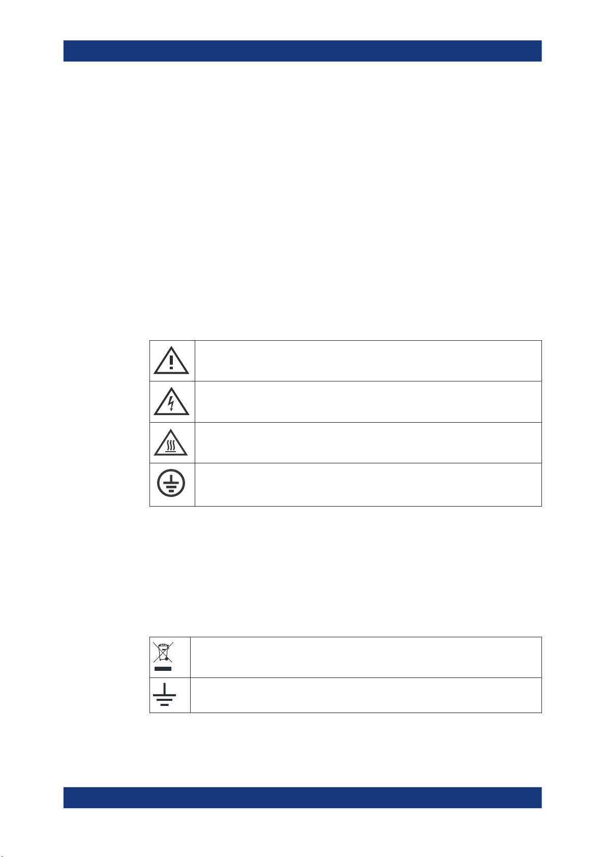
Meaning of safety labels
Safety labels on the product warn against potential hazards.
Potential hazard
Read the product documentation to avoid personal injury or product damage.
Electrical hazard
Indicates live parts. Risk of electric shock, fire, personal injury or even death.
Hot surface
Do not touch. Risk of skin burns. Risk of fire.
Protective conductor terminal
Connect this terminal to a grounded external conductor or to protective ground. This connec-
tion protects you against electric shock if an electric problem occurs.
1.2 Labels on the R&S LCX
Labels on the casing inform about:
●
Personal safety, see "Meaning of safety labels" on page 11.
●
Product and environment safety, see Table 1-1.
Table 1-1: Labels regarding R&S
LCX and environment safety
Labeling in line with EN 50419 for disposal of electrical and electronic equipment after the product has come to the end of its service life. For more information, see "Disposing electrical and
electronic equipment" on page 226.
Grounding connection
11User Manual 1179.2260.02 ─ 02

R&S®LCX Series
1.3 Warning messages in the documentation
Safety and regulatory information
Korea certification class A
Chassis grounding connection
Noiseless ground.
The input signal at these connectors must be free from external voltages. The measurement
results are otherwise incorrect.
A warning message points out a risk or danger that you need to be aware of. The signal word indicates the severity of the safety hazard and how likely it will occur if you do
not follow the safety precautions.
DANGER
Imminently hazardous situation. Will result in death or serious injury if not avoided.
WARNING
Potentially hazardous situation. Could result in death or serious injury if not avoided.
CAUTION
Potentially hazardous situation. Could result in minor or moderate injury if not avoided.
NOTICE
Potential risks of damage. Could result in damage to the supported product or to other
property.
1.4 Korea certification class A
이 기기는 업무용(A급) 전자파 적합기기로서 판매자 또는 사용자는 이 점을 주의하시기
바라며, 가정외의 지역에서 사용하는 것을 목적으로 합니다.
12User Manual 1179.2260.02 ─ 02

R&S®LCX Series
2 Welcome
2.1 Key features
Welcome
Key features
The R&S LCX LCR Meter sets standards in analyzing passive components. It provides
the full range of measurements to characterize resistors, capacitors and inductors, and
displays results as absolute, relative or average values.
Outstanding key features are:
●
Frequency range: 4 kHz to 300 kHz (R&S LCX100), and up to 10 MHz
(R&S LCX200)
●
Measurement functions: L, C, R, |Z|, X, |Y|, G, B, D, Q, Φ, ∆, M, N
●
Basic accuracy: 0.05 %
●
Continuous, manual or external control via interface, binning interface or trigger
●
Digital I/O ports and binning function for automatic sorting of components (option
R&S LCX-K107)
●
LAN, USB interface for remote control, optionally IEEE-488 (GPIB) bus interface
(option R&S NG-B105)
For details on the specification, see the data sheet.
13User Manual 1179.2260.02 ─ 02

R&S®LCX Series
3 Documentation overview
3.1 Getting started manual
3.2 User manual
Documentation overview
Instrument security procedures
This section provides an overview of the R&S LCX user documentation. Unless specified otherwise, you find the documents on the R&S LCX product page at:
www.rohde-schwarz.com/manual/lcx
Introduces the R&S LCX and describes how to set up and start working with the product. Includes basic operations, typical measurement examples, and general information, e.g. safety instructions, etc. A printed version is delivered with the instrument.
The user manual contains the description of all instrument modes and functions. It also
provides an introduction to remote control, a complete description of the remote control
commands with programming examples, and information on maintenance, instrument
interfaces and error messages. Includes the contents of the getting started manual.
The user manual is also available for download or for immediate display on the Internet.
3.3 Tutorials
Tutorials offer guided examples and demonstrations on operating the R&S LCX. They
are provided on the product page of the internet.
3.4 Service manual
Describes the performance test for checking compliance with rated specifications, firmware update and maintenance.
The service manual is available for registered users on the global Rohde & Schwarz
information system (GLORIS): https://gloris.rohde-schwarz.com
3.5 Instrument security procedures
Deals with security issues when working with the R&S LCX in secure areas. It is available for download on the Internet.
14User Manual 1179.2260.02 ─ 02

R&S®LCX Series
3.6 Printed safety instructions
3.7 Data sheets and brochures
3.8 Release notes and open-source acknowledgment
Documentation overview
Remote control driver
Provides safety information in many languages. The printed document is delivered with
the product.
The data sheet contains the technical specifications of the R&S LCX. It also lists the
firmware applications and their order numbers, and optional accessories.
The brochure provides an overview of the instrument and deals with the specific characteristics.
See www.rohde-schwarz.com/brochure-datasheet/lcx
(OSA)
The release notes list new features, improvements and known issues of the current
firmware version, and describe the firmware installation.
The open-source acknowledgment document provides verbatim license texts of the
used open source software.
See www.rohde-schwarz.com/firmware/lcx
3.9 Application notes, application cards, white papers, etc.
These documents deal with special applications or background information on particular topics.
See www.rohde-schwarz.com/application/lcx
3.10 Remote control driver
The instrument drivers enable remote control via the corresponding interfaces. The
drivers and installation instructions are available for download on the product page at
www.rohde-schwarz.com/driver/lcx.
15User Manual 1179.2260.02 ─ 02

R&S®LCX Series
4 Getting started
4.1 Preparing for use
4.1.1 Lifting and carrying
4.1.2 Unpacking and checking
Getting started
Preparing for use
This chapter contains the same information as the getting started manual.
Here, you can find basic information about setting up the product for the first time.
See "Lifting and carrying the product" on page 9.
1. Unpack the R&S LCX carefully.
2. Retain the original packing material. Use it when transporting or shipping the
R&S LCX later.
3. Using the delivery notes, check the equipment for completeness.
4. Check the equipment for damage.
If the delivery is incomplete or equipment is damaged, contact Rohde & Schwarz.
See also: Chapter 13, "Transporting", on page 224.
4.1.3 Choosing the operating site
Specific operating conditions ensure proper operation and avoid damage to the product and connected devices. For information on environmental conditions such as ambient temperature and humidity, see the data sheet.
See also "Choosing the operating site" on page 10.
Electromagnetic compatibility classes
The electromagnetic compatibility (EMC) class indicates where you can operate the
product. The EMC class of the product is given in the data sheet under "General data".
●
Class B equipment is suitable for use in:
– Residential environments
– Environments that are directly connected to a low-voltage supply network that
supplies residential buildings
16User Manual 1179.2260.02 ─ 02
R&S®LCX Series
4.1.4 Setting up the R&S LCX
4.1.4.1 Placing the R&S LCX on a bench top
Getting started
Preparing for use
●
Class A equipment is intended for use in industrial environments. It can cause
radio disturbances in residential environments due to possible conducted and radiated disturbances. It is therefore not suitable for class B environments.
If class A equipment causes radio disturbances, take appropriate measures to
eliminate them.
See also:
●
"Setting up the product" on page 10
●
"Intended use" on page 9
To place the product on a bench top
1. Place the product on a stable, flat and level surface. Ensure that the surface can
support the weight of the product. For information on the weight, see the data
sheet.
CAUTION! Foldable feet can collapse. See "Setting up the product" on page 10.
2.
Always fold the feet completely in or out. With folded-out feet, do not place anything on top or underneath the product.
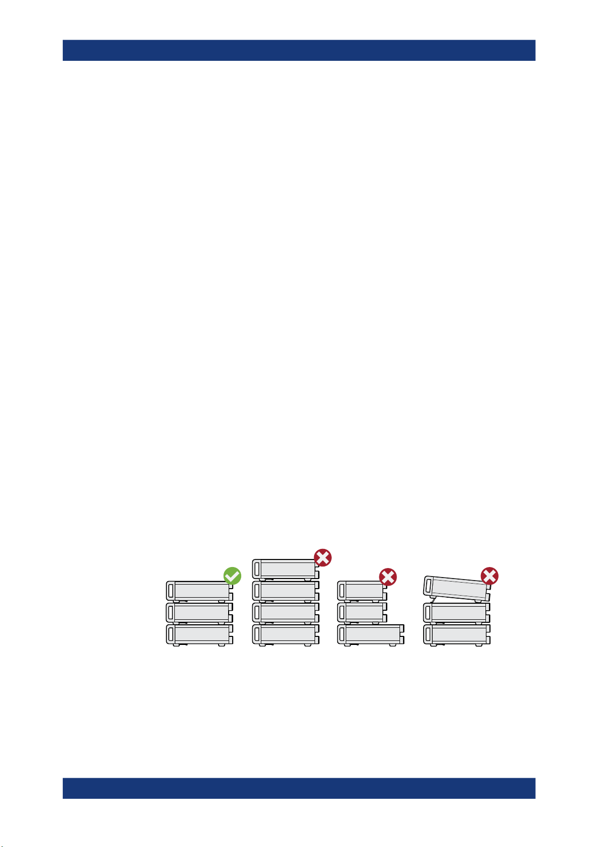
WARNING! A stack of products can fall over and cause injury. Never stack more
3.
than three products on top of each other. Instead, mount them in a rack.
Stack as follows:
● If the products have foldable feet, fold them in completely.
● All products must have the same dimensions (width and length).
● Do not exceed a total load of 50 kg placed on the product at the bottom of the
stack.
Left
Middle left = Stacked incorrectly, too many products
Middle right = Stacked incorrectly, different dimensions
Right = Stacked incorrectly, different dimensions, folded-out feet
NOTICE! Overheating can damage the product.
4.
= Stacked correctly
Prevent overheating as follows:
17User Manual 1179.2260.02 ─ 02

R&S®LCX Series
4.1.4.2 Mounting the R&S LCX in a rack
Getting started
Preparing for use
● Keep a minimum distance of 10 cm between the fan openings of the product
and any object in the vicinity.
● Do not place the product next to heat-generating equipment such as radiators
or other products.
To prepare the rack
1. Observe the requirements and instructions in "Setting up the product" on page 10.
NOTICE! Insufficient airflow can cause overheating and damage the product.
2.
Design and implement an efficient ventilation concept for the rack.
Mounting the R&S LCX in a rack
To mount the R&S LCX in a rack:
1. Use an adapter kit that fits the dimensions of the R&S LCX to prepare the
R&S LCX for rack mounting.
a) Order the rack adapter kit designed for the R&S LCX. For the order number,
see the data sheet.
b) Mount the adapter kit. Follow the assembly instructions provided with the
adapter kit.
2. Lift the R&S LCX to shelf height.
3. Push the R&S LCX onto the shelf until the rack brackets fit closely to the rack.
4. Tighten all screws at the rack brackets with a tightening torque of 1.2 Nm to secure
the R&S LCX at the rack.
Unmounting the R&S LCX from a rack
To unmount the R&S LCX from a rack:
1. Loosen the screws at the rack brackets.
2. Bring the lifting equipment to shelf height.
3. Remove the R&S LCX from the rack.
4. If placing the R&S LCX on a bench top again, unmount the adapter kit from the
R&S LCX. Follow the instructions provided with the adapter kit.
4.1.5 Considerations for test setup
Cable selection and electromagnetic interference (EMI)
Electromagnetic interference (EMI) can affect the measurement results.
18User Manual 1179.2260.02 ─ 02

R&S®LCX Series
Getting started
Preparing for use
To suppress electromagnetic radiation during operation:
●
Use high-quality shielded cables, especially for the following connector types:
– Connectors for external devices
Double-shielded data cables. The length of data cables must not exceed 3 m.
– Connectors for signal transmission
Shielded coaxial cables. The length of signal cables must not exceed 1 m.
We recommend that you use the R&S LCX-Z11 BNC-to-BNC extension (1 m)
from Rohde & Schwarz.
– BNC
Double-shielded BNC cables.
– USB
Double-shielded USB cables. The length of passive USB cables must not
exceed 1 m.
– LAN
At least CAT6+ cables
– IEEE-488 (GPIB)
Double-shielded cables. We recommend that you use the double-shielded
cable "R&S HZ72" from Rohde & Schwarz.
●
Always terminate open cable ends.
●
Ensure that connected external devices comply with EMC regulations.
Signal input and output levels
Information on signal levels is provided in the data sheet. Keep the signal levels within
the specified ranges to avoid damage to the product and connected devices.
4.1.6 Connecting to power
For safety information, see "Connecting to power" on page 10.
When using the R&S LCX the first time, you can skip Replacing the external bias fuse
and Replacing the line fuse.
If there are any problems during power-on or malfunction of the bias, check the condition of the mains fuse. Also check the fuse for the external bias input as described in
these instructions. They explain how to check and change the protective fuses, if necessary.
Replacing the external bias fuse
The bias voltage input of the R&S LCX is protected by a fuse of type IEC 60127-2/5F0.5L/250V (order no. 0009.5463.00). The externally accessible fuse is at the rear
panel.
To check and exchange the external bias fuse:
NOTICE! Risk of instrument damage. Malfunction of the fuse that protects the bias
1.
voltage input from overload can damage the circuitry of the instrument.
19User Manual 1179.2260.02 ─ 02

R&S®LCX Series
Getting started
Preparing for use
Do not use either fuse type other than specified, nor a defective fuse, and never
short-circuit the fuse.
Make sure that you have disconnected the R&S LCX from the mains.
2. Check the condition of the external bias fuse.
3. If necessary, install the fuse type required for the external bias voltage.
a) Unscrew the fuse holder with a suitable screwdriver.
b) Pull out the fuse holder.
c) Replace the fuse by a fuse of the specified type.
d) Insert the fuse holder into the external bias inlet.
When inserting the fuse holder, press it slightly and tighten it.
Replacing the line fuse
The product is protected by one fuse of type IEC 60127-2/5-T2.0H/250V
(order no. 0020.7546.00). The externally accessible fuse is part of the IEC socket of
the power supply at the rear panel.
To exchange the line fuse:
1. Check the available supply voltage.
The mains voltage must be within the voltage range as denoted on the instrument.
The label is at the rear panel, on the left of the "AC power" connector and power
switch.
The power supply module covers a wide power supply range and normally does
not require adjustment.
2. If the power supply exceeds the permissible range, contact Rohde & Schwarz customer service.
WARNING! The fuse is part of the main power supply. Handling the fuse while the
3.
power is on can lead to electric shock.
If necessary, exchange the fuse required for the supply voltage.
4. Before changing the fuse:
a) Set the switch on the power supply to position [0].
b) Disconnect the R&S LCX from the power source.
5. Replace the line fuse.
a) Unplug the power cable.
b) Press the plastic lock on the bottom of the fuse holder inwards using a screw-
driver (with a blade width of approximately 2 mm).
A narrow guide on the bottom of the fuse holder denotes the insertion point.
When unlocking the mechanism, compression springs automatically push the
fuse holder outwards.
c) Pull out the fuse holder.
d) Check the condition of the fuse.
20User Manual 1179.2260.02 ─ 02

R&S®LCX Series
Getting started
Preparing for use
e) Replace the fuse by a fuse of the specified type.
A label next to the fuse holder also indicates the fuse type and its characteris-
tics.
f) Note: The protruding contact springs must not be deformed. Align the fuse
holder with the guide bar facing the socket.
Carefully slide the fuse holder against the spring pressure into the slot until the
plastic lock latches.
Connecting to power
To connect the instrument to the mains:
1. Check the available supply voltage.
The mains voltage must be within the voltage range as denoted on the instrument.
The label is at the rear panel, on the left of the "AC power" connector and power
switch.
The power supply module covers a wide power supply range and normally does
not require adjustment.
2. If the power supply exceeds the permissible range, contact Rohde & Schwarz customer service.
3.
If necessary, ground the instrument using the grounding connection
A ground connector socket is at the front panel to connect a ground cable with a
banana plug.
As an alternative, a ground terminal at the rear panel enables you to connect a
ground cable firmly with a screw:
a) At the rear panel, unscrew the screw of the ground terminal using a cross-
recess screw driver.
b) Attach a ground cable with a ring terminal and pass the screw through it.
c) Fasten the screw.
d) Connect the cable to ground.
4. Plug the AC power cable into the "AC power" connector.
The power supply switch connector is at the rear panel. Only use the power cable
delivered with the R&S LCX.
5. Plug the AC power cable into a power outlet with ground contact.
The required ratings are listed next to the AC connector and in the data sheet.
4.1.7 Connecting to LAN
.
Establishing the LAN connection
The R&S LCX provides Ethernet (LAN) connectivity. Provided the corresponding rights
are assigned, you can use these interfaces for remote control and data transfer from a
controller PC. The controller PC must also be connected in the network.
The "LAN" connector is at the rear panel.
21User Manual 1179.2260.02 ─ 02
R&S®LCX Series
Getting started
Preparing for use
To connect the R&S LCX to the LAN:
1. Connect the "LAN" socket using an RJ-45 cable to the LAN.
By default, the R&S LCX configuration uses DHCP that assigns the IP address
automatically.
NOTICE! If the R&S LCX cannot obtain an IP address automatically, or cannot
2.
establish the connection, the icon in the status bar turns red.
Possible reasons are that the LAN does not support DCHP or requires a specific
TCP/IP configuration, or that the connection is missing.
To troubleshoot the problem, proceed as follows:
a) Check if you have connected both, the R&S LCX and the controller PC to the
LAN.
b) Consult your network administrator to request support and an IP address, if
necessary.
c) If necessary, assign the IP address manually as described in "Assigning the
LAN interface addresses manually" on page 159.
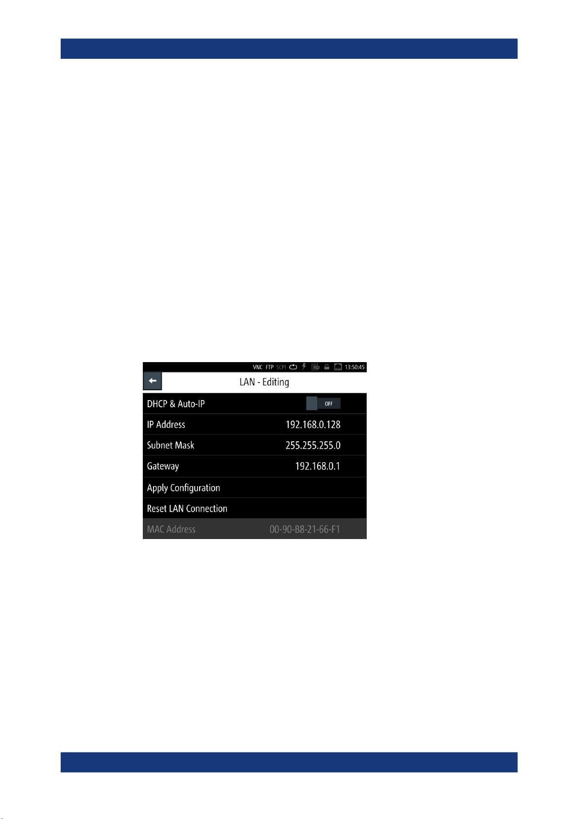
If switched on and connected, the R&S LCX indicates the address information and
LAN parameters in the "Ethernet Settings dialog".
Figure 4-1: LAN settings dialog
4.1.8 Connecting USB devices
The "USB A" connector is at the front panel. You can connect or disconnect all USB
devices from the R&S LCX during operation. But do not remove an external USB memory stick while the instrument is saving data, since it leads to loss of data.
22User Manual 1179.2260.02 ─ 02

R&S®LCX Series
Getting started
Preparing for use
To connect USB storage devices
USB storage devices, such as memory sticks, allow easy data transfer from or to the
R&S LCX. You can also use them for firmware updates.
► Connect the USB storage device to the "USB A" connector.
If you use the front panel connectors, connect the USB storage device directly,
without connecting cable. Connecting cables can cause electromagnetic radiation
and impair the measurement result.
To connect USB devices with external power supply
If you need more power for the external bias, you can use an USB device with external
power supply.
NOTICE! Connected devices with external power supply can feed back current into
1.
the 5 V power supply of the USB interface and thus damage the R&S LCX.
Make sure that there is no connection between the positive pole of the power supply and the +5 V power pin of the USB interface (VBUS).
2. Connect the USB storage device to the "USB A" connector at the front panel.
4.1.9 Connecting a test fixture
The R&S LCX enables you to measure passive components like capacitors, coils,
resistors, transformers. To measure such components requires the use of suitable
measurement adapters, in this context considered as test fixtures.
For information on the test fixtures available for the R&S LCX, see Measurement Set-
ups > About Test Fixtures.
The test fixtures are connected firmly to the four BNC connectors H POT (high potential), H CUR (high current), L POT low potential) and L CUR (low current) at the front
panel.
The following instructions describe the mechanical connection of the adapter only.
Before starting a measurement, consider the prerequisites and steps to be performed
before as described in Chapter 4.3, "Trying out the instrument", on page 32.
Connecting a test fixture to the instrument
To connect a 4-terminal test fixture to the R&S LCX:
NOTICE! Check all terminals to make sure that they are not damaged.
1.
NOTICE! Before connecting, discharge all components. Externally supplied voltage
can damage the BNC connectors of the R&S LCX.
Turn the levers at the "BNC" connectors of the test fixture to the left to release the
lock (1).
23User Manual 1179.2260.02 ─ 02

R&S®LCX Series
Getting started
Preparing for use
2
1
Figure 4-2: Connecting a test fixture
2. Carefully plug the test fixture to the four "BNC" measurement connectors of the
R&S LCX (2).
3. Turn all levers to the right to tighten the connection (3).
3
Figure 4-3: Fastening the test fixture
The mechanical test setup is ready for operation.
Connecting a test fixture with the BNC-to-BNC extension
If you are using the BNC-to-BNC extension (option R&S LCX-Z11), you can connect all
devices as described in Connecting a test fixture to the instrument. We recommend
that you keep the order as follows:
1. Connect the BNC-to-BNC to the R&S LCX.
Proceed as described in step 1.
2. Connect the test fixture to the extension.
24User Manual 1179.2260.02 ─ 02

R&S®LCX Series
4.1.10 Switching on or off
Getting started
Instrument tour
Switching on the product
The product is off but connected to power.
1. Set the switch on the power supply to position [I].
The power supply switch connector is on the rear panel.
The R&S LCX starts, and the front panel keys light up briefly.
2. Press the power key for a second.
The power is on the front panel.
The instrument checks the system, boots the operating system, and then starts the
R&S LCX firmware.
The power lights green.
When starting for the first time, the R&S LCX starts with the default settings. When
restarting the instrument, the settings depend on the instrument configuration
before shut-down.
Shutting down the product
► Press the power key.
All current settings are saved and the operating system shuts down.
The power changes to gray (off).
To disconnect from power
The product is in the standby state.
NOTICE! Risk of data loss. If you disconnect the product from power when it is in
1.
the ready state, you can lose settings and data. Shut it down first.
Set the switch on the power supply to position [0].
2. Disconnect the product from the power source.
4.2 Instrument tour
The following topics help you to get familiar with the instrument and perform the first
steps:
●
Front panel tour
●
Rear panel tour
The sections explain the controls and connections at the front and back of the
R&S LCX. For specifications of the interfaces, see the data sheet.
The meanings of the labels on the R&S LCX are described in Chapter 1.2, "Labels on
the R&S LCX", on page 11.
25User Manual 1179.2260.02 ─ 02
R&S®LCX Series
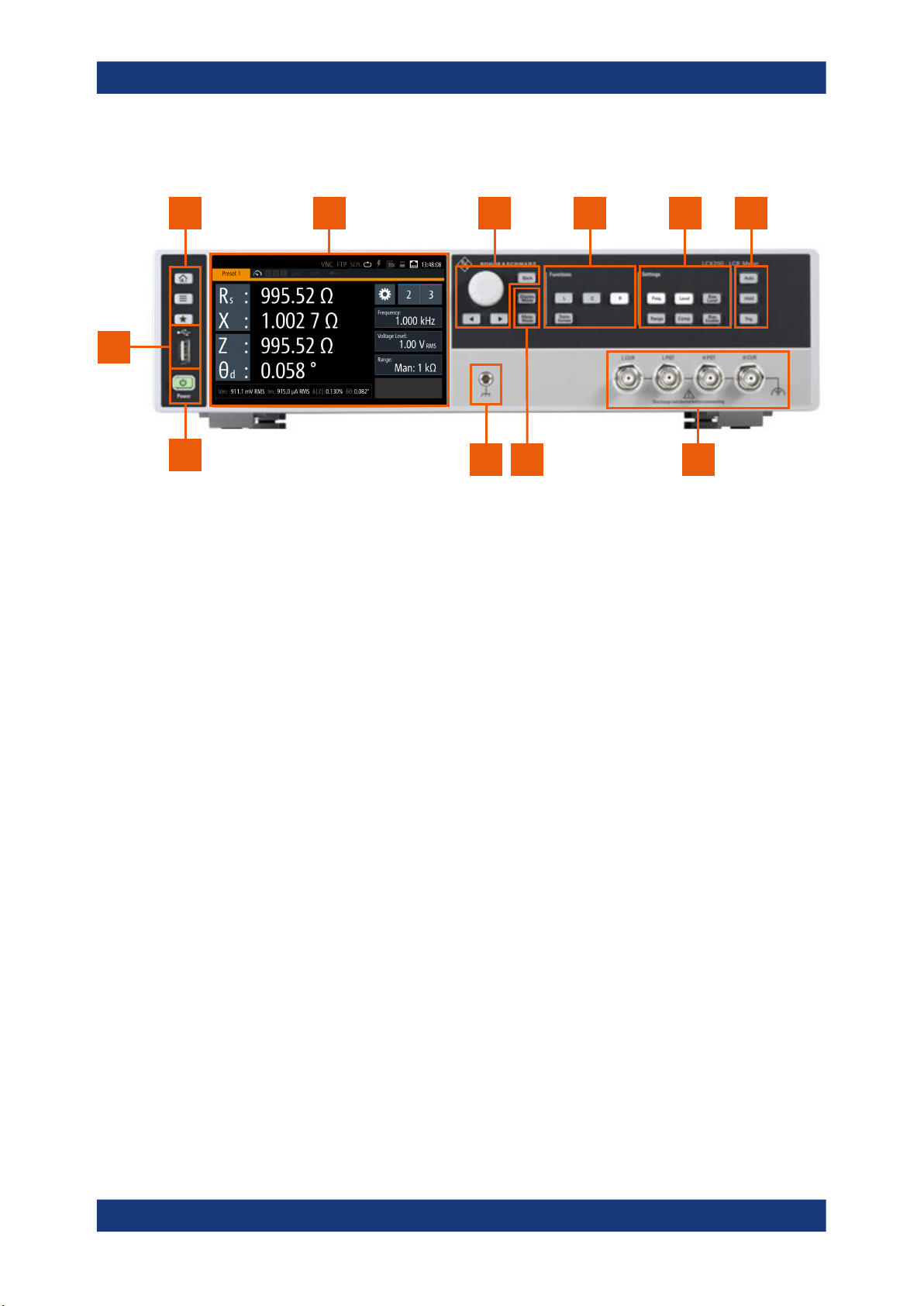
4.2.1 Front panel tour
1 2 3 4 5 6
11
Getting started
Instrument tour
10
Figure 4-4: R&S LCX front panel
1 = Basic display keys, see "Basic display keys" on page 27
2 = Touchscreen display, see Chapter 4.2.1.1, "Touchscreen display", on page 26
3 = Navigation controls, see "Navigation controls" on page 27
4 = Function keys, see "Function keys" on page 28
5 = Setting keys, see "Settings keys" on page 28
6 = Measurement control keys, see "Measurement control keys" on page 28
7 = BNC measurement connectors, see "L CUR, L POT, H CUR, H POT" on page 29
8 = Measurement mode keys, see "Measurement mode keys" on page 28
9 = Ground connector, see "Ground socket" on page 29
10 = POWER key, see "POWER On/Standby key" on page 29
11 = USB host connector
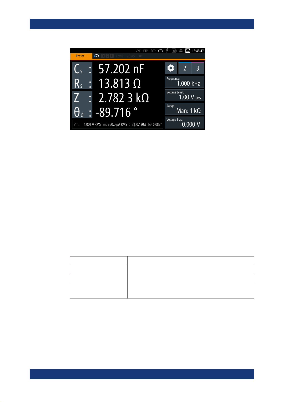
4.2.1.1 Touchscreen display
The color TFT touchscreen at the front panel is the graphical user interface. It shows
the measurement readings, status information and settings, and provides access to
settings dialogs.
8
79
26User Manual 1179.2260.02 ─ 02
R&S®LCX Series
Getting started
Instrument tour
Figure 4-5: Touchscreen display
For details on the screen display, see Chapter 4.4.2.1, "Understanding the display
information", on page 36.
The touch-sensitive panel provides an alternative means of user interaction for quick
and easy handling of the instrument, see Chapter 4.4.2, "Means of manual interaction",
on page 35.
4.2.1.2 Keys
This section introduces the functionality of the hardkeys at the front panel. These controls lead you to menus and dialogs displayed on the screen. For information on how to
operate the instrument, see Chapter 4.4.2, "Means of manual interaction",
on page 35.
Basic display keys
The utility keys arrange different windows on the display.
Table 4-1: Display keys
Display key Assigned functions
[home] Returns to the initial feature screen.
[settings] Displays a menu list for accessing general instrument functions.
[★ (User)] Executes a previously assigned user action.
Press and hold accesses the favorites menu for assigning a user action.
Navigation controls
The navigation controls include a rotary knob and navigation keys. They allow you to
navigate within the display or within dialogs, see Chapter 4.4.2, "Means of manual
interaction", on page 35.
27User Manual 1179.2260.02 ─ 02
R&S®LCX Series
Getting started
Instrument tour
Table 4-2: Navigation controls
Key Assigned functions
[Rotary knob] Selects, activates or confirms settings.
[◀] / [▶] Moves the cursor in entry fields.
[Back] Returns to a previous level in menus, or closes a view.
Measurement mode keys
The measurement controls enable you to select the measurement mode and view of
the representation of the measurement readings.
Table 4-3: Measurement mode controls
Key Assigned functions
[Meas. Mode] Selects either continuous or manually triggered measurement mode.
[Display Mode] Selects the display of measurement readings.
Function keys
The keys in the function panel select the parameters for the measurement.
Table 4-4: Measurement function controls
Key Assigned functions
[L] Selects the function for measuring inductance.
[C] Selects the function for capacity measurement.
[R] Selects the measurement for a resistor.
[Transformer] Selects the transformer measurement.
Settings keys
The keys in the settings panel enable you to select measurement ranges and additional parameters for executing the measurement.
Table 4-5: Measurement function controls
Key Assigned functions
[Freq.] Sets the signal frequency.
[Range] Selects the impedance range.
[Level] Sets the level.
[Comp.] Opens the "Open/Short/Load Correction" dialog for quick access.
[Bias Level] Sets the bias voltage and current.
[Bias Enable] Activates internal or external bias.
Measurement control keys
These keys provide control during the measuring procedure.
28User Manual 1179.2260.02 ─ 02

R&S®LCX Series
4.2.1.3 Connectors
Getting started
Instrument tour
Table 4-6: Navigation controls
Key Assigned functions
[Auto] Activates the automatic selection of the measurement function.
[Hold] Freezes the measurement range, on the screen indicated with prefix "Hold:"
at the range value.
[Trig.] Triggers a measurement manually.
POWER On/Standby key
The [On/Standby] key switches the instrument from the standby to the ready state or
vice versa.
The [On/Standby] lights green when the instrument is switched on, see Chapter 4.1.10,
"Switching on or off", on page 25.
The measurement input connectors and the USB connector are on the front panel.
L CUR, L POT, H CUR, H POT
Four BNC sockets:
●
"L CUR" (low current): signal output for series measurements (signal generator).
●
"L POT" (low potential): signal input for parallel measurement (voltage measurements).
●
"H CUR" (high current): signal input for series measurements (current measurements).
●
"H POT" (high potential): signal input and output for parallel measurements (measurement bridge).
Ground socket
Protective ground socket (4 mm banana socket) to secure the R&S LCX, e.g. with a
grounded external conductor.
The front panel ground socket is directly connected to the mains safety ground by the
line cord.
See Table 1-1.
USB A
Female USB (universal serial bus) connector of type A (host USB). You can connect a
USB memory stick, e.g., to record and export measurement data, to capture screenshots, or to update the firmware.
How to: Chapter 4.1, "Preparing for use", on page 16
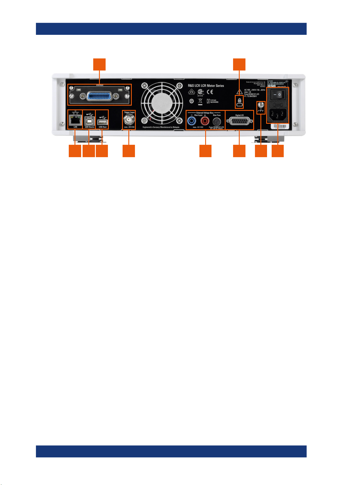
4.2.2 Rear panel tour
This section provides an overview of the connectors at the rear panel of the instrument.
For technical data of the connectors, see the data sheet.
29User Manual 1179.2260.02 ─ 02
R&S®LCX Series
Getting started
Instrument tour
1 2
345678910
Figure 4-6: R&S LCX rear panel
1 = IEEE-488 interface, see "IEC 625/IEEE 488" on page 30
2 = Kensington lock, see "Kensington lock" on page 30
3 = AC power connector and power switch, see "AC power supply" on page 30
4 = Ground terminal, see "Ground terminal" on page 31
5 = D-sub connector, see "Digital I/O" on page 31
6 = Bias connectors and fuse holder, see "External Voltage Bias" on page 31, "BIAS Fuse" on page 31
7 = Trigger input connector, see "Trigger Input" on page 31
8 = USB host connector, see "USB A" on page 29
9 = USB device connector, see "USB B" on page 31
10 = Ethernet (LAN) interface connector, see "LAN" on page 31
IEC 625/IEEE 488
Option: R&S NG-B105
General purpose interface bus (GPIB) interface to connect a computer for remote con-
trol of the R&S LCX.
See "Establishing the GPIB remote control connection" on page 158.
Kensington lock
Flat key security slot to prevent the instrument from removal.
The locking system consists of a small, metal-reinforced hole with a metal anchor and
a rubberized metal cable that is secured with a key lock. The loop at the end of the
cable allows you to tie the unit to a fixed object.
AC power supply
Mains power supply with power switch, fuse holder and IEC socket.
●
Mains power switch:
Switch for connecting and disconnecting the internal power supply from the power
source, see Chapter 4.1.10, "Switching on or off", on page 25.
●
Fuse holder
Socket for the fuse securing the line voltage. Depending on the power supply system, the corresponding fuse must be plugged before connecting to power. See
"Connecting to power" on page 21.
●
IEC socket
30User Manual 1179.2260.02 ─ 02
 Loading...